Embed Size (px)
Citation preview
41-973.5R
2
Type PM Line of Relays For Pilot Wire MonitoringAnd Transferred Tripping
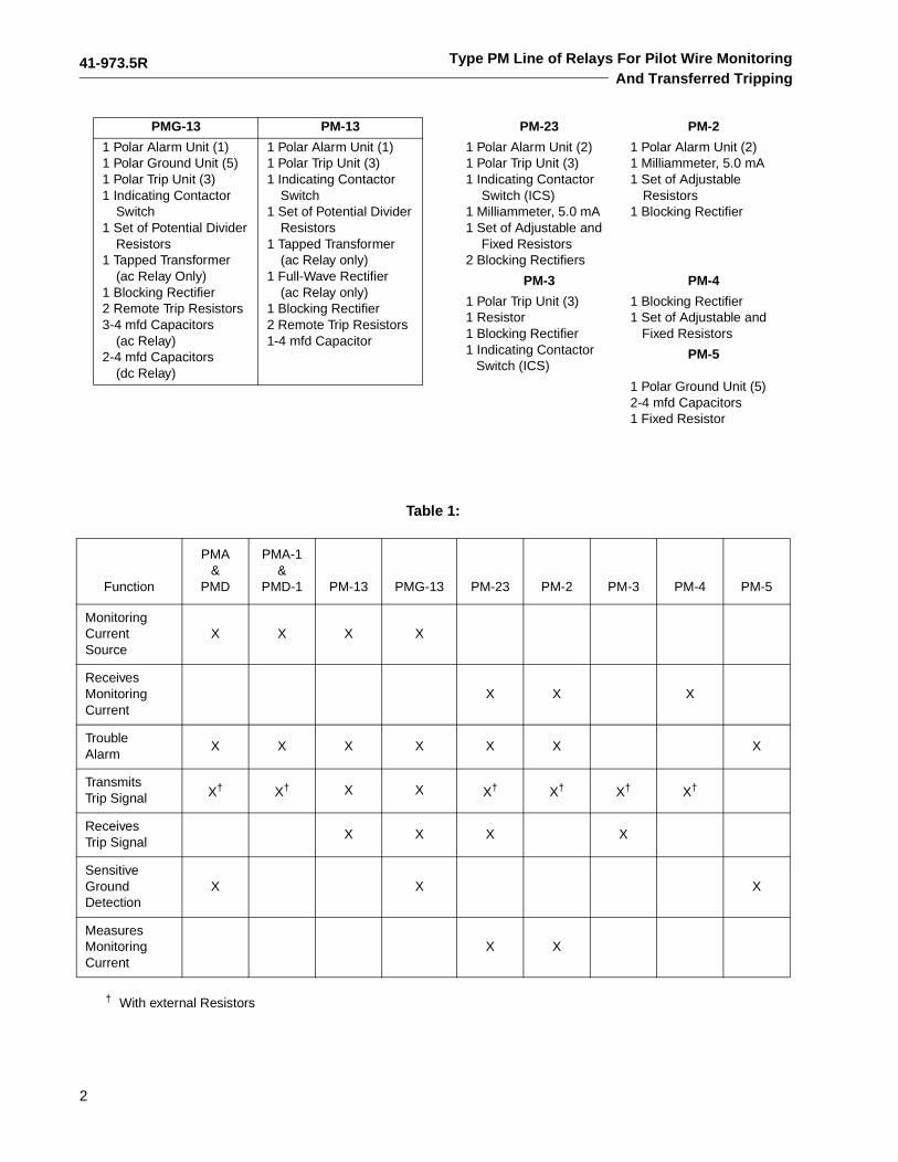
PMG-13 PM-13
1 Polar Alarm Unit (1)1 Polar Ground Unit (5)1 Polar Trip Unit (3)1 Indicating Contactor
Switch1 Set of Potential Divider
Resistors1 Tapped Transformer
(ac Relay Only)1 Blocking Rectifier2 Remote Trip Resistors3-4 mfd Capacitors
(ac Relay)2-4 mfd Capacitors
(dc Relay)
1 Polar Alarm Unit (1)1 Polar Trip Unit (3)1 Indicating Contactor
Switch1 Set of Potential Divider
Resistors1 Tapped Transformer
(ac Relay only)1 Full-Wave Rectifier
(ac Relay only)1 Blocking Rectifier2 Remote Trip Resistors1-4 mfd Capacitor
PM-23 PM-2
1 Polar Alarm Unit (2)1 Polar Trip Unit (3)1 Indicating Contactor
Switch (ICS)1 Milliammeter, 5.0 mA1 Set of Adjustable and
Fixed Resistors2 Blocking Rectifiers
1 Polar Alarm Unit (2)1 Milliammeter, 5.0 mA1 Set of Adjustable
Resistors1 Blocking Rectifier
PM-3 PM-4
1 Polar Trip Unit (3)1 Resistor1 Blocking Rectifier1 Indicating Contactor
Switch (ICS)
1 Blocking Rectifier1 Set of Adjustable and
Fixed Resistors
PM-5
1 Polar Ground Unit (5)2-4 mfd Capacitors1 Fixed Resistor
† With external Resistors
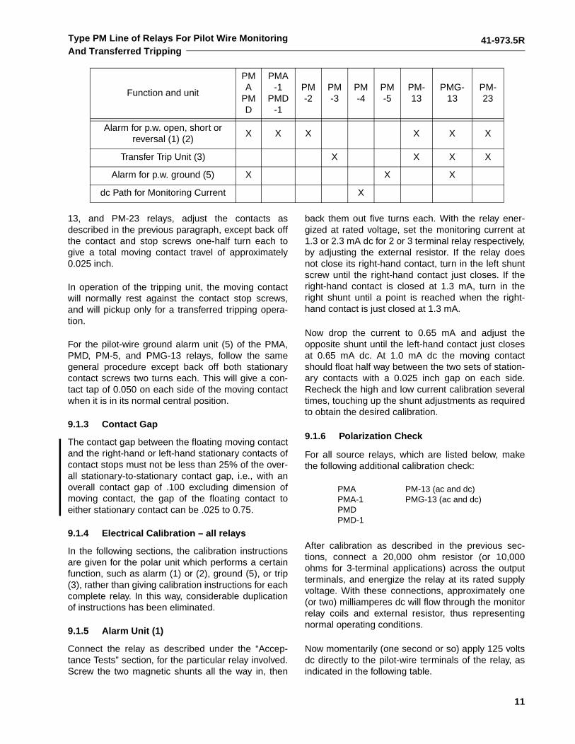
Table 1:
Function
PMA&
PMD
PMA-1 &
PMD-1 PM-13 PMG-13 PM-23 PM-2 PM-3 PM-4 PM-5
MonitoringCurrentSource
X X X X
ReceivesMonitoringCurrent
X X X
TroubleAlarm
X X X X X X X
TransmitsTrip Signal X† X† X X X† X† X† X†
ReceivesTrip Signal
X X X X
Sensitive GroundDetection
X X X
Measures Monitoring Current
X X
41-973.5R
3
Type PM Line of Relays For Pilot Wire MonitoringAnd Transferred Tripping
2.1 POLAR UNIT
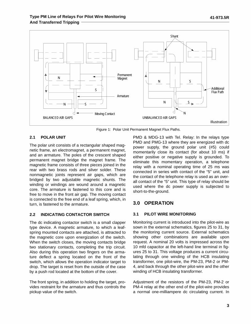
The polar unit consists of a rectangular shaped mag-netic frame, an electromagnet, a permanent magnet,and an armature. The poles of the crescent shapedpermanent magnet bridge the magnet frame. Themagnetic frame consists of three pieces joined in therear with two brass rods and silver solder. Thesenonmagnetic joints represent air gaps, which arebridged by two adjustable magnetic shunts. Thewinding or windings are wound around a magneticcore. The armature is fastened to this core and isfree to move in the front air gap. The moving contactis connected to the free end of a leaf spring, which, inturn, is fastened to the armature.
2.2 INDICATING CONTACTOR SWITCH
The dc indicating contactor switch is a small clappertype device. A magnetic armature, to which a leaf-spring mounted contacts are attached, is attracted tothe magnetic core upon energization of the switch.When the switch closes, the moving contacts bridgetwo stationary contacts, completing the trip circuit.Also during this operation two fingers on the arma-ture deflect a spring located on the front of theswitch, which allows the operation indicator target todrop. The target is reset from the outside of the caseby a push rod located at the bottom of the cover.
The front spring, in addition to holding the target, pro-vides restraint for the armature and thus controls thepickup value of the switch.
PMD & MDG-13 with Tel. Relay: In the relays typePMD and PMG-13 where they are energized with dcpower supply, the ground polar unit (#5) couldmomentarily close its contact (for about 10 ms) ifeither positive or negative supply is grounded. Toeliminate this momentary operation, a telephonerelay with a nominal operating time of 25 ms wasconnected in series with contact of the “5” unit, andthe contact of the telephone relay is used as an over-all contact of the “5” unit. This type of relay should beused where the dc power supply is subjected toshort-to-the-ground.
3.0 OPERATION
3.1 PILOT WIRE MONITORING
Monitoring current is introduced into the pilot-wire assown in the external schematics, figures 25 to 31, bythe monitoring current source. External schematicsshowing other combinations are available uponrequest. A nominal 20 volts is impressed across the10 mfd capacitor at the left-hand line terminal in fig-ures 25 to 31. This voltage produces a current circu-lating through one winding of the HCB insulatingtransformer, one pilot-wire, the PM-23, PM-2 or PM-4, and back through the other pilot-wire and the otherwinding of HCB insulating transformer.
Adjustment of the resistors of the PM-23, PM-2 orPM-4 relay at the other end of the pilot-wire providesa normal one-milliampere dc circulating current. In
N
N
S
S
N
N
S
S
Moving Contact
Armature
PermanentMagnet
BALANCED AIR GAPS UNBALANCED AIR GAPSN
AdditionalFlux Path
Shunt
Figure 1: Polar Unit Permanent Magnet Flux Paths.
Illustration
41-973.5R
4
Type PM Line of Relays For Pilot Wire MonitoringAnd Transferred Tripping
the case of three-terminal lines, the monitoringsource relay output current is 2 mA in order to pro-vide each receiving end relay with 1 mA. The alarmunit of the monitoring current source relay is adjustedto float between the high and low current contacts withnormal monitoring current. The PM-23, receiving endalarm relay, is adjusted to float between the low-currentalarm contact and a contact stop with 1 mA flowing.
3.2 SHORT CIRCUITS
A complete or partial short circuit on the pilot-wiresincreases the current in the current-source relay,causing the high-current alarm contacts to close. Theresulting current decrease in the PM-23 relay closesthe alarm contact. Short circuits of 5000 ohms or lesswill be detected.
3.3 OPEN CIRCUITS
Current decreases to zero in all relays. Low currentalarm contact of the current source relay closes.Alarm contact of PM-23 relay closes.
3.4 REVERSE WIRES
On applications using the PM-23 relay, currentincreases in the sending end relay to close the highcurrent alarm contacts. Current drops to zero in thePM-23 relay monitoring coil to close the low-currentalarm contacts.
If the pilot-wire should be opened, the low-currentcontacts of the (2) unit will close. If the pilot-wire isthen reconnected with reversed connections, the (2)unit low-current contacts will remain closed. Thecapacitor at the sending end discharges through thepilot-wire and the trip unit (3) circuit when the pilot-wire is connected reversed. This would momentarilyoperate the trip unit (3) contact which would causean incorrect trip; however, this is prevented by the (2)unit low-current contacts which connect a 2.25Kresistor across the trip unit (3) coil. The 2.2K resistorremains connected across the trip-unit (3) coil untilthe pilot-wire is connected properly.
The current decreases in both sending and receivingend relays when the PM-2, or PM-4 relays are used.Low-current alarm contacts close.
3.5 GROUNDS
The voltage-divider circuit of the PMA, PMD, andPMG-13 source relays has its midpoint groundedthrough a current-limiting resistor. Thus, a pilot-wireground will cause an increase in current in one coil
circuit, and a decrease in the other one. This unbal-ance in the current flowing through the two windings(5) of the ground alarm relay unit will cause it to closeone of its contacts (depending on which point wire isgrounded) to give an alarm. Grounds of 10,000 ohmsor less will be detected.
For adding the sensitive ground detection wherePMA-1, PMD-1, or PM-13 relays have been installed,the PM-5 relay can be added to the circuitry, asshown in figure 30. This relay also has a 10,000 ohmground sensitivity.
3.6 TRANSFERRED TRIPPING
Breakers located at the PMG-13 or PM-13 and PM-3or PM-23 stations can be tripped by the application ofa dc voltage to the pilot-wires at remote locations, asshown in figures 25 to 31. Transferred tripping can beeffected from any location by applying 48 volts dc(through dropping resistors when required) to thepilot-wire with polarity opposite to that of the monitor-ing voltage. When tripping the PM-23, the current isincreased above 2.0 mA, in reverse direction, toclose the trip contact. When tripping the PMG-13 orPM-13, the reversed dc voltage operates the trip unit(3).
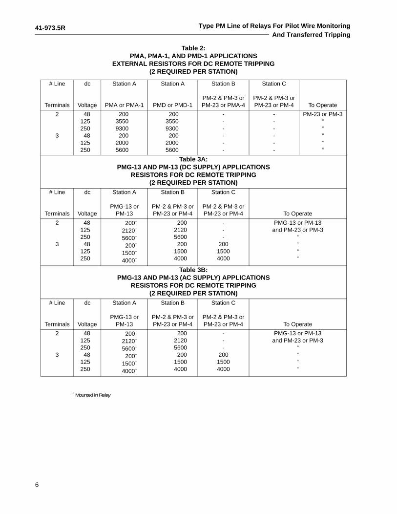
See Tables 2 and 3 for tripping resistor values. Nomi-nal tripping currents is 5 mA at all rated voltages.
3.7 POLAR UNIT
Polar unit flux paths are shown in figure 1. With bal-anced air gaps, permanent magnet flux flows in twopaths, one through the front, and one through therear gaps. This flux produces north and south poles,as shown. By turning the left shunt in, some of theflux is forced through the armature, making it a northpole. Thus, reducing the left-hand rear gap will pro-duce a force tending to pull the armature to the right.Similarly reducing the right-hand gap will make thearmature a south pole and produce a force tending topull the armature to the left.
The alarm unit contacts of the sending and receivingend relays are biased to move to the left when therelay is deenergized. The PMG-13 or PM-13 andPM-23 trip unit contact is biased to move to the leftwhen the relay is deenergized. The PM-5 is adjustedso that the moving contact floats when the relay isdeenergized.
41-973.5R
5
Type PM Line of Relays For Pilot Wire MonitoringAnd Transferred Tripping
4.0 CHARACTERISTICS
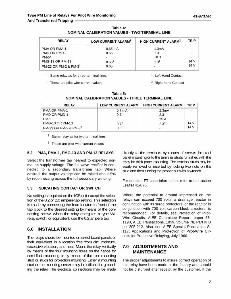
4.1 NOMINAL CALIBRATION VALUES
Nominal current values to close contacts are listed inTables 4 and 5.
4.2 VOLTAGE RATINGS
Supply voltage ratings of the monitoring sourcerelays to obtain continuous current as follows:
voltage impressed on the pilot-wire is a nominal 20volts for monitoring, and 48 volts for tripping. Supplyvoltage ratings to obtain remote tripping are: 48, 125,and 250 volts dc.
4.3 COIL RESISTANCE (EACH WINDING)
4.4 PM-4 AND PM-23 RESISTANCE
Nominal PM-4 and PM-23 total resistance whenadjusted for service is 20,000 ohms less pilot-wireloop resistance at 1 mA.
4.5 PMA, PMA-1 AND AC PMG-13, PM-13 BUR-DEN
4.6 RECTIFIERS
4.7 REMOTE TRIPPING
Remote trip resistors are listed in Table 2 and 3 for48, 125, and 250 volts dc.
The relays have sufficient thermal capacity to with-stand 20 mA dc continuously when remote tripping.Nominal trip currents in the tripping relays are 5.0 mAdc with 48, 125, and 250 volts dc supply and a 2000ohm pilot wire.
4.8 TRIP CIRCUIT
The main contacts will safely close 30 amperes at250 volts dc and the seal-in contacts of the indicatingcontactor switch will safely carry this current longenough to trip a circuit breaker.
The indicating contactor switch has two taps that pro-vide a pickup setting of 0.2 or 2 amperes. To changetaps requires connecting the lead located in front ofthe tap block to the desired setting by means of ascrew connection.
4.9 TRIP CIRCUIT CONSTANT
Indicating Contactor Switch (ICS)
5.0 SETTINGS
Operating units of all relays are adjusted in the fac-tory to the values listed in Tables 4 and 5 to a toler-ance of ±8%. No settings are required on these units.
For all 48/125 volt dc relays, connect jumpers acrossresistors as shown on the internal schematics.
5.1 PM-4, PM-2, AND PM-23 RELAYS
Adjust the resistors in the PM-4, PM-2, or PM-23 relayor relays to a value of 1 mA dc with the monitoring cir-cuits connected for service. Use the milliammeter in thePM-23 for this purpose or use a portable milliammeterwith a resistance of less than 200 ohms. Where it is notpractical no three-terminal lines to adjust both receivingrelays simultaneously, set one receiving relay for 18,000ohms total resistance (including relay coil and resistors)by measurement prior to final adjustment of the otherreceiving relay. This procedure will minimize the changein monitoring current in the first relay to be adjustedwhen making the final adjustment of the second relay.
dc 48, 125, and 250 volts
ac120 volts, 60 hertz (Primary taps 100, 110, 120 and 130)
Alarm coil (1)two terminal linethree terminal line
1050-1250 ohms700-900 ohms
Alarm coil (2) 2200-2600 ohms
Trip coil (3) 1800-2200 ohms
Ground Alarm coil 5200-5800 ohms
0.5 VA at tap voltage 2-terminal line relay
1.0 VA at tap voltage 3-terminal line relay
Approximate forward resistance 560 ohms at 1 mA300 ohms at 2 mA
RatingContinuous forward current amperes 1
Continuous backvoltage-rms volts 200
Tap Resistance
0.2 ampere 6.5 ohms dc
2.0 ampere 0.15 ohms dc
41-973.5R
6
Type PM Line of Relays For Pilot Wire MonitoringAnd Transferred Tripping
Table 2: PMA, PMA-1, AND PMD-1 APPLICATIONS
EXTERNAL RESISTORS FOR DC REMOTE TRIPPING(2 REQUIRED PER STATION)
# Line
Terminals
dc
Voltage
Station A
PMA or PMA-1
Station A
PMD or PMD-1
Station B
PM-2 & PM-3 orPM-23 or PMA-4
Station C
PM-2 & PM-3 orPM-23 or PM-4 To Operate
2
3
48125250
48125250
20035509300200
20005600
20035509300
20020005600
------
------
PM-23 or PM-3“““““
Table 3A:PMG-13 AND PM-13 (DC SUPPLY) APPLICATIONS
RESISTORS FOR DC REMOTE TRIPPING(2 REQUIRED PER STATION)
# Line
Terminals
dc
Voltage
Station A
PMG-13 orPM-13
Station B
PM-2 & PM-3 orPM-23 or PM-4
Station C
PM-2 & PM-3 orPM-23 or PM-4 To Operate
2
3
48125250
48125250
200†
2120†
5600†
200†
1500†
4000†
20021205600200
15004000
---
20015004000
PMG-13 or PM-13and PM-23 or PM-3
““““
Table 3B:PMG-13 AND PM-13 (AC SUPPLY) APPLICATIONS
RESISTORS FOR DC REMOTE TRIPPING(2 REQUIRED PER STATION)
# Line
Terminals
dc
Voltage
Station A
PMG-13 orPM-13
Station B
PM-2 & PM-3 orPM-23 or PM-4
Station C
PM-2 & PM-3 orPM-23 or PM-4 To Operate
2
3
48125250
48125250
200†
2120†
5600†
200†
1500†
4000†
20021205600200
15004000
---
20015004000
PMG-13 or PM-13and PM-23 or PM-3
““““
† Mounted in Relay
41-973.5R
7
Type PM Line of Relays For Pilot Wire MonitoringAnd Transferred Tripping
5.2 PMA, PMA-1, PMG-13 AND PM-13 RELAYS
Select the transformer tap nearest to expected nor-mal ac supply voltage. The full wave rectifier is con-nected to a secondary transformer tap. Wheredesired, the output voltage can be raised about 5%by reconnecting across the full secondary winding.
5.3 INDICATING CONTACTOR SWITCH
No setting is required on the ICS unit except the selec-tion of the 0.2 or 2.0 ampere tap setting. This selectionis made by connecting the lead located in front of thetap block to the desired setting by means of the con-necting screw. When the relay energizes a type WLrelay switch, or equivalent, use the 0.2 ampere tap.
6.0 INSTALLATION
The relays should be mounted on switchboard panels ortheir equivalent in a location free from dirt, moisture,excessive vibration, and heat. Mount the relay verticallyby means of the four mounting holes on the flange forsemi-flush mounting or by means of the rear mountingstud or studs for projection mounting. Either a mountingstud or the mounting screws may be utilized for ground-ing the relay. The electrical connections may be made
directly to the terminals by means of screws for steelpanel mounting or to the terminal studs furnished with therelay for thick panel mounting. The terminal studs may beeasily removed or inserted by locking two nuts on thestud and then turning the proper nut with a wrench.
For detailed FT case information, refer to InstructionLeaflet 41-076.
Where the potential to ground impressed on therelays can exceed 700 volts, a drainage reactor inconjunction with its surge protectors, or the reactor inconjunction with 700 volt carbon-block arresters, isrecommended. For details, see Protection of Pilot-Wire Circuits, AIEE Committee Report, paper 58-1190, AIEE Transactions, 1959, Volume 78, Part III Bpp. 205-212. Also, see AIEE Special Publication S-117, Applications and Protection of Pilot-Wire Cir-cuits for Protective Relaying, July 1960.
7.0 ADJUSTMENTS ANDMAINTENANCE
The proper adjustments to insure correct operation ofthis relay have been made at the factory and shouldnot be disturbed after receipt by the customer. If the
Table 4: NOMINAL CALIBRATION VALUES - TWO TERMINAL LINE
RELAY LOW CURRENT ALARM1 HIGH CURRENT ALARM2 TRIP
PMA OR PMA-1PMD OR PMD-1PM-5†
PMG-13 OR PM-13
PM-23 OR PM-2 & PM-3†
0.65 mA0.65-
0.65‡
0.65
1.3mA1.3±0.3
1.3‡
-
---
14 V14 V
† Same relay as for three-terminal lines 1 Left-Hand Contact
‡ These are pilot-wire current values 2 Right-hand Contact
Table 5: NOMINAL CALIBRATION VALUES - THREE TERMINAL LINE
RELAY LOW CURRENT ALARM HIGH CURRENT ALARM TRIP
PMA OR PMA-1PMD OR PMD-1PM-5†
PMG-13 OR PM-13
PM-23 OR PM-2 & PM-3†
0.7 mA0.7-
0.7‡
0.65
2.3mA2.3±0.3
2.3‡
-
---
14 V14 V
† Same relay as for two-terminal lines
‡ These are pilot-wire current values
41-973.5R
8
Type PM Line of Relays For Pilot Wire MonitoringAnd Transferred Tripping
adjustments have been changed, the relay takenapart for repairs, or if it is desired to check the adjust-ments at regular maintenance periods, the instruc-tions in the succeeding sections should be followed.
7.1 ACCEPTANCE TESTS
The following tests are recommended when the relayis received from the factory. If the relay does not per-form as specified below, the relay either is not prop-erly calibrated or it contains a defect. (Relays mustbe tested in the case.)
7.1.1 Indicating Contactor Switch (ICS)
Close the contact of the tripping unit and pass suffi-cient direct current through the trip circuit to close thecontacts of the ICS unit. This value of current shouldnot be greater than the particular ICS tap settingbeing used (0.2 or 2.0). The indicator target shoulddrop freely.
7.1.2 PMA and PMA-1 Relays
Alarm Unit (1)
Set the primary tap on 120 volts. Connect a variableresistor of approximately 20,000 ohms in series witha low-range dc milliammeter across terminals 6 and7 with the instrument positive connected to terminal7. Apply 120 volts at rated frequency to terminals 4and 5. Adjust the 20,000 ohm resistor to obtain a cur-rent of one mA dc. For a three-terminal line relay, usea 10,000 ohm resistor and set the current to 2 mA dc.At this value, the moving contact of the alarm or mon-itoring relay unit (1) should float between the two setsof stationary contacts. In the PMA relay, the groundalarm unit (5) contact should also float. (This contactwill also float when the relay is deenergized.)Increase and decrease the one or two milliamperemonitoring current to check the calibration valueslisted in Tables 4 and 5.
Ground Unit (5)
Reconnect the 20,000 ohm resistor. For the PMArelay only, short terminals 7 and 3. The contact of theground alarm unit (5) should close to the right whenthe relay is energized. Remove the short, and con-nect it between terminals 6 and 3. The ground alarmunit (5) should close to the left. The action of themonitoring unit (1) contact is of no significance in thissimulated pilot-wire ground test. To check the pickupcurrent of the ground detector, first remove to the20,000 ohm resistor from terminals 6 and 7. Connecta 0-1 dc milliammeter in series with a variable resis-
tor of about 50,000 ohms between terminals 3 and 6.The ground unit should close its left-hand contact atapproximately 0.3 mA dc. With the milliammeter andresistor connected between terminals 3 and 7, theright-hand contact should close at 0.3 mA dc.
7.1.3 PMD and PMD-1 Relays
Alarm and Ground Units
Connect an adjustable 20,000 ohm resistor (or10,000 ohms for a 3-terminal relay) in series with adc milliammeter across terminals 6 and 7 with theinstrument positive connected to terminal 7. Applyrated dc voltage to terminals 8 and 9 with positive onterminal 9. Now check the PMD and PMD-1 relays,following the procedure given in the previous sectionfor the PMA and PMA-1 relays, respectively. Note,however, that terminal 5 of the PMD relay corre-sponds to terminal 3 of the PMA relay.
7.1.4 PM-2, PM-3, and PM-23 Relays
Alarm Unit (2)
Apply a variable dc voltage of approximately 20 voltsto relay terminals 8 and 9 (terminal 9 positive) of thePM-2 or PM-23 relay. Adjust the voltage to obtain areading of one mA on the relay milliammeter. Themonitoring polar unit (2) contacts should float.Reduce the current gradually. The monitoring alarmcontacts should close at 0.65 mA dc. The trippingunit (3) of the PM-23 relay should not move duringthis test. The milliammeter has been adjusted to read1 mA ± 5%. As a result the pointer may not read zerofor a zero current condition.
Tripping Unit (3)
to check the PM-3 relay or the tripping unit of the PM-23 relay, apply the variable dc voltage in series withan external milliammeter to relay terminals 8 and 9with terminal 8 positive for the PM-23 relay, or termi-nal 9 positive for the PM-3 relay. When checking thepickup of the PM-23 trip unit block open the alarmunit contacts (2) so as to remove the shunt resistorfrom around the trip coil (3).
The tripping relay unit (3) should pickup with positiveaction at 14 volts dc and should drop out at approxi-mately 10 volts. The alarm unit of the PM-23 relaywill not operate during this test.
7.1.5 PM-4 Relay
This device is simply a set of resistors and a diode toconnect into the pilot-wire circuit to provide a path for
41-973.5R
9
Type PM Line of Relays For Pilot Wire MonitoringAnd Transferred Tripping
the monitoring current. The resistors can be checkedwith an ohmmeter, and the diode can be checkedeither with an ohmmeter, or as explained in the sec-tion entitled “Rectifier Check” under “Routine Mainte-nance”. If an ohmmeter is used, the difference inforward and reverse resistance readings obtainedwill be dependent on the current flowing through thediode.
7.1.6 PM-5 Relay
Apply 5 volts dc in series with a 0-1 dc milliammeterand a 20,000 ohm variable resistor to terminals 6 and7 with positive on terminal 6. The left-hand contactshould close at approximately 0.3 mA. Now apply thesame circuit to terminals 8 and 9 with positive on ter-minal 9. The right-hand contact should close atapproximately 0.3 mA.
7.1.7 PM-13 Relays – ac and dc
Alarm Unit (1)
Connect a variable 20,000 ohm resistor (10,000ohms for a 3-terminal line relay) in series with a dcmilliammeter across terminals 8 and 9 with the instru-ment positive on terminal 9. For the ac relay, set theprimary tap on 120 volts. Now apply the rated supplyvoltage to terminals 4 and 5. This will be 48, 125, or250 volts dc, or 120 volts ac as indicated on the relaynameplate. Adjust the variable resistor to obtain acurrent of one mA for a 2-terminal line relay, or 2 mAfor a 3-terminal relay. At this value, the moving con-tacts of the alarm or monitoring (1) relay unit (theupper polar unit) should float between the two sets ofstationary contacts. Increase and decrease the oneor 2 mA monitoring current to check the calibrationvalues listed in Tables 4 and 5.
Tripping Unit (3)
To check the operation of the tripping unit 3 (thelower polar unit), apply a dc potential across termi-nals 16 (positive) and 20 (negative). The trippingpolar unit should pick up at 14 volts. The resistanceof the series dropping resistors for transferred trip-ping (listed in Table 3A and Table 3B) can bechecked with an ohmmeter. The circuit location ofthese resistors can readily be seen from the externalschematic, figure 27.
7.1.8 PMG-13 Relays – ac and dc
Alarm and Tripping Units
Follow the procedure given in the previous sectionfor the ac and dc PM-13 relays.
Ground Unit (5)
Connect the 20,000 ohm (or 10,000 ohm) resistorand milliammeter across terminals 8 and 9. Withrated voltage applied and one mA (or 2 mA) flowing,successively short circuit terminals 3 and 8, then 3and 9. The ground alarm unit 5 (lower polar unit)should move first to the left, then to the right. Tocheck the pickup current of the ground detector, firstremove the 20,000 ohm resistor from terminals 8 and9. Connect a 0-1 dc milliammeter in series with avariable resistor of about 50,000 ohms between ter-minals 3 and 8. The left-hand contact should close atapproximately 0.3 mA dc. With the milliammeterresistor connected between terminals 3 and 9, theright-hand contact should close at 0.3 mA dc. Theexternal schematic diagrams for these relays areshown in figures 27 and 29.
8.0 ROUTINE MAINTENANCE
! CAUTION
DO NOT make any performance check, calibra-tion tests, or adjustments while the PM relays areenergized or connected to the pilot-wires, to pre-vent the possibility of inadvertently causing abreak operation. The PM relays may be removedfrom service for testing, without jeopardizingHCB relay protection, providing that the connec-tions between the 10 mfd capacitor and the HCBinsulating transformer are not disturbed.
8.1 CONTACTS
All contacts should be periodically cleaned. A contactburnisher Style number 182A836H01 is recom-mended for this purpose. The use of abrasive mate-rial for cleaning contacts is not recommendedbecause of the danger of embedding small particlesin the face of the soft silver and thus impairing thecontact.
8.2 OPERATIONAL CHECK
In addition to cleaning contacts, it is recommendedthat an operational check be performed periodicallyby opening and short circuited the pilot-wires, as wellas grounding term at the relay terminals.
NOTE: These pilot-wire faults should not be applieddirectly to the pilot-wires when the HCB relaysare in service. It is recommended that the tripcircuits of the PM relays be opened (where trip-
41-973.5R
10
Type PM Line of Relays For Pilot Wire MonitoringAnd Transferred Tripping
ping is used), to prevent the possibility of inad-vertently tripping the associated circuit breakerduring testing. If the relays do not perform asexpected, and diode failure is suspected, thediode tests described in the following sectionmay be performed.
8.3 RECTIFIER (DIODE) CHECK (AC RELAYS ONLY)
If there is suspicion of a rectifier (diode) failure, apply30 volts dc reverse voltage (positive on cathode)through a 300 ohm resistance to the diode. Measurethe voltage across the diode. If this voltage is notessentially 30 volts, the diode is short circulated.Now apply 30 volts dc in the forward directionthrough the 300 ohm resistor, and measure the volt-age across the resistor. If the voltage is not essen-tially 30 volts, the diode may have a high forwardresistance. If voltage is zero, the diode is open-cir-cuited.
9.0 CALIBRATION
If the relay has been dismantled or the calibrationhas been disturbed, use the following procedure forcalibration. (Relays must be tested in the case.)
With the permanent magnet removed, see that themoving armature floats in the central area of the air-gap between the poles of the polar unit frame. If nec-essary, loosen the core screw in the center rear ofthe unit and shift the core and contact assembly untilthe armature floats. (This can best be done with thepolar unit removed from the relay.) Then retighten thecore screw and replace he permanent magnet withthe dimple (north pole) on the magnet to the leftwhen viewed from the front.
9.1 POLAR UNITS – GENERAL
The following mechanical adjustments are given as aguide, and some deviation from them may be neces-sary to obtain proper electrical calibration.
9.1.1 Magnetic Shunt Adjustment
The sensitivity of the polar unit is adjusted by meansof two magnetic, screw-type shunts at the rear of theunit, as shown in figure 1. These shunt screws areheld in proper adjustment by a flat strip spring acrossthe back of the polar unit frame, so no locking screwsare required. Looking at the relay, front view, turningout the right-hand shunt to open the right-hand airgap decreases the amount of current required toclose the right-hand contact. Conversely, drawing outthe left-hand shunt increases the amount of currentrequired to close the right-hand contact, or
decreases the amount of current required to closethe left-hand contact (with the proper direction of cur-rent flow). Also, if a relay trips to the right at theproper current, the dropout current can be raised byturning in the right-hand shunt. The two shunt-screwadjustments are not independent, however, and acertain amount of trimming adjustment of both shuntscrews is generally necessary to obtain the desiredpickup and dropout calibration.
In general, the farther out the two shunt screws areturned, the greater the toggle action will be, and as aresult, the lower the dropout current. For the trippingunits (3) of the PM-3, PM-13, and PM-23 relays, tog-gle action is desirable, with a dropout current around75 percent of the pickup current. For the monitoringalarm relay units, toggle action is not desired.Instead, the armature is adjusted to float between thepole faces at a given current (1 or 2 mA), and tomove gradually toward the high or low current alarmas the coil current is increased or decreased. Simi-larly, the floating adjustment of the armature of theground alarm unit (5) requires that both shunt screwsbe turned in relatively far. Then the armature willmove gradually to the left or right as the currentthrough the two #5 coils is unbalanced.
The electrical calibration of the polar unit is alsoaffected by the contact adjustment as this changesthe position of the polar unit armature. Do not changethe contact adjustment without rechecking the electri-cal calibration.
The chart on page 11 indicates the units present ineach relay.
9.1.2 Contact Adjustment – all relays
For all monitoring alarm units, designed (1) or (2),turn in all the stationary contact and contact stopscrews until they just touch the moving contact.Advance the screws to hold the armature in the cen-tral portion of the magnetic air gap between the two-pole faces. (The stationary contact screws have around silver contact face; the stop screws do nothave this silver facing.) Now back off all the contactand contact stop screws one full turn. This will give atotal contact travel of 0.050 inch. When the relay isproperly calibrated, some touch-up adjustment maybe necessary so that double contacts will both closeat the same current value. The contact gap betweenthe floating moving contact and the right-hand or left-hand stationary contacts or contact stops will beapproximately 0.025 inch when the relay is in opera-tion.
For the tripping (3) units of the PM-3, PM-13, PMG-
41-973.5R
11
Type PM Line of Relays For Pilot Wire MonitoringAnd Transferred Tripping
13, and PM-23 relays, adjust the contacts asdescribed in the previous paragraph, except back offthe contact and stop screws one-half turn each togive a total moving contact travel of approximately0.025 inch.
In operation of the tripping unit, the moving contactwill normally rest against the contact stop screws,and will pickup only for a transferred tripping opera-tion.
For the pilot-wire ground alarm unit (5) of the PMA,PMD, PM-5, and PMG-13 relays, follow the samegeneral procedure except back off both stationarycontact screws two turns each. This will give a con-tact tap of 0.050 on each side of the moving contactwhen it is in its normal central position.
9.1.3 Contact Gap
The contact gap between the floating moving contactand the right-hand or left-hand stationary contacts ofcontact stops must not be less than 25% of the over-all stationary-to-stationary contact gap, i.e., with anoverall contact gap of .100 excluding dimension ofmoving contact, the gap of the floating contact toeither stationary contact can be .025 to 0.75.
9.1.4 Electrical Calibration – all relays
In the following sections, the calibration instructionsare given for the polar unit which performs a certainfunction, such as alarm (1) or (2), ground (5), or trip(3), rather than giving calibration instructions for eachcomplete relay. In this way, considerable duplicationof instructions has been eliminated.
9.1.5 Alarm Unit (1)
Connect the relay as described under the “Accep-tance Tests” section, for the particular relay involved.Screw the two magnetic shunts all the way in, then
back them out five turns each. With the relay ener-gized at rated voltage, set the monitoring current at1.3 or 2.3 mA dc for 2 or 3 terminal relay respectively,by adjusting the external resistor. If the relay doesnot close its right-hand contact, turn in the left shuntscrew until the right-hand contact just closes. If theright-hand contact is closed at 1.3 mA, turn in theright shunt until a point is reached when the right-hand contact is just closed at 1.3 mA.
Now drop the current to 0.65 mA and adjust theopposite shunt until the left-hand contact just closesat 0.65 mA dc. At 1.0 mA dc the moving contactshould float half way between the two sets of station-ary contacts with a 0.025 inch gap on each side.Recheck the high and low current calibration severaltimes, touching up the shunt adjustments as requiredto obtain the desired calibration.
9.1.6 Polarization Check
For all source relays, which are listed below, makethe following additional calibration check:
After calibration as described in the previous sec-tions, connect a 20,000 ohm resistor (or 10,000ohms for 3-terminal applications) across the outputterminals, and energize the relay at its rated supplyvoltage. With these connections, approximately one(or two) milliamperes dc will flow through the monitorrelay coils and external resistor, thus representingnormal operating conditions.
Now momentarily (one second or so) apply 125 voltsdc directly to the pilot-wire terminals of the relay, asindicated in the following table.
PMAPMA-1PMDPMD-1
PM-13 (ac and dc)PMG-13 (ac and dc)
Function and unit
PMA
PMD
PMA-1
PMD-1
PM-2
PM-3
PM-4
PM-5
PM-13
PMG-13
PM-23
Alarm for p.w. open, short or reversal (1) (2)
X X X X X X
Transfer Trip Unit (3) X X X X
Alarm for p.w. ground (5) X X X
dc Path for Monitoring Current X
41-973.5R
12
Type PM Line of Relays For Pilot Wire MonitoringAnd Transferred Tripping
After momentary application of the transfer-trip volt-ages as just explained, recheck the calibration of themonitoring alarm unit (1). If it has changed, makenecessary trimming adjustments of the shunt screwsuntil there is no change in calibrating of the alarm unit(1) after the transfer-trip voltage has been applied.The purpose of this test is to compensate for thesmall residual magnetism in the relay unit. Theground alarm unit (5) will not be affected by this testas the ampere turns of the two windings cancel eachother.
9.1.7 Alarm Unit (2)
For the alarm unit of the PM-2 or PM-23 relays,adjust the shunts so that the relay moving contactfloats at one mA dc and closes the left-hand contactat 0.65 mA dc. The moving contact should float mid-way between the contact and contact stop at 1.0 mAdc. There is no high current calibration for this relayunit.
Now apply 125 volts dc momentarily (one second orso) across the alarm unit coil-circuit terminals in adirection to operate the alarm relay. Then recheckthe alarm unit calibration. If there is any change,touch up the shunt adjustments until there is nochange in calibration after 125 Vdc has been applied.
9.1.8 Tripping Unit (3)
To calibrate the tripping unit of the PM-3, PM-13,PMG-13, or PM-23 relays, apply a dc voltage asexplained below, to the following relay terminals:
Momentarily (one second or so) apply 125 Vdc to theterminals shown in the chart. Starting with bothshunts all the way in, turn out the right-hand shunt
screw until the relay closes its right-hand trip contactat 14 volts dc.
NOTE:In the calibration of a PM-23, the alarm unit(2) contact must be blocked open so as notto affect the tripping unit pickup. (This willgive approximately 2 mA through the relaycoil.) Now draw out the left-hand shuntuntil the relay resets with toggle action(not gradually) at not less than 10 volts dc.When the calibration is approximately cor-rect, again apply 125 volts dc to the indi-cated terminals, then recheck the pickupand dropout voltage, making any neces-sary trimming adjustments of the shunts.When the relay is properly adjusted, theapplication of 125 volts dc will not changethe pickup or dropout voltage points. Therelay should trip and reset with toggleaction in this application. This will requireboth shunt screws to be withdrawn fartherthan for floating action.
9.1.9 Ground Alarm Unit (5)
For the PM-5 relay, turn both shunt screws all theway in, then back them out five turns each. Pass acurrent of 0.3 mA dc in terminal 6 and out terminal 7.Following the same general procedure as describedpreviously in the section entitled “Alarm Unit (1),”adjust the shunt screws so that the left-hand contactcloses at 0.3 mA. Now pass 0.3 mA dc in terminal 9and out terminal 8, and adjust for closing of the right-hand contact at 0.3 mA. Recheck both pickup pointsseveral times, and make trimming adjustments ofboth shunts as required to obtain contact closing at0.3 mA dc in each direction.
For the ground unit (5) of the PMA, PMD, and PMG-13 relays, connect a variable resistance of about50,000 ohms in series with a 0-1 dc milliammeterbetween the terminals indicated in the followingtable:
Relay Terminals for MomentaryApplication of 125 V dc
PMA, PMA-1PMD, PMD-1
PM-13 (ac or dc)PMG-13 (ac or dc)
POS.6
8
NEG.7
9
Relaysdc Voltage
Pos. Neg.
PM-3PM-13 (ac or dc)PMG-13 (ac or dc)PM-23
91688
82099
RelayRelay Terminals
L.H. Contact Check R.H. Contact Check
PMAPMDPMG-13
3† and 65† and 63† and 8
† Milliammeter positive to this terminal
3 and 7†
5 and 7†
3 and 9†
41-973.5R
13
Type PM Line of Relays For Pilot Wire MonitoringAnd Transferred Tripping
Turn the shunts all the way in, then back them outfive turns each. With the relay connected as shown inthe left-hand column of the table, apply rated voltageto the relay and adjust the 50,000 ohm resistor for0.3 mA dc. Now following the procedure in the previ-ous paragraph for the PM-5 relay, adjust the shuntsuntil the left-hand contact closes at 0.3 mA dc.Change the connections as indicated in the right-hand column, and adjust the opposite shunt until theright-hand contact closes. Recheck back and forthseveral times and make necessary trimming adjust-ments to obtain pickup at 0.3 mA in each direction.The armature will move gradually as the current ischanged for this relay unit.
9.1.10 ICS Unit
Close the main relay tripping contact circuit with ajumper connected directly across the contact termi-nals of the polar unit. Pass sufficient direct current
through the relay trip circuit to close the contacts ofthe ICS unit. This value of current should not begreater than the ICS tap setting being used (0.2 or2.0). The indicator target should drop freely. The con-tact gap should be approximately 0.047 inchbetween the bridging moving contact and the adjust-able stationary contacts. The bridging moving con-tact should touch both stationary contactssimultaneously.
10.0 RENEWAL PARTS
Repair work can be done most satisfactorily at thefactory. However, interchangeable parts can be fur-nished to the customers who are equipped for doingrepair work. When ordering parts, always give thecomplete nameplate data.
41-973.5R
14
Type PM Line of Relays For Pilot Wire MonitoringAnd Transferred Tripping
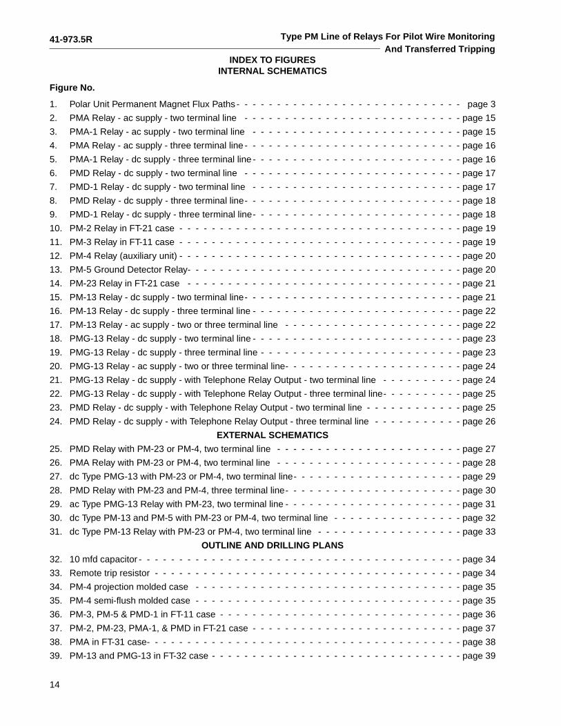
INDEX TO FIGURESINTERNAL SCHEMATICS
Figure No.
1. Polar Unit Permanent Magnet Flux Paths - - - - - - - - - - - - - - - - - - - - - - - - - - - - page 3
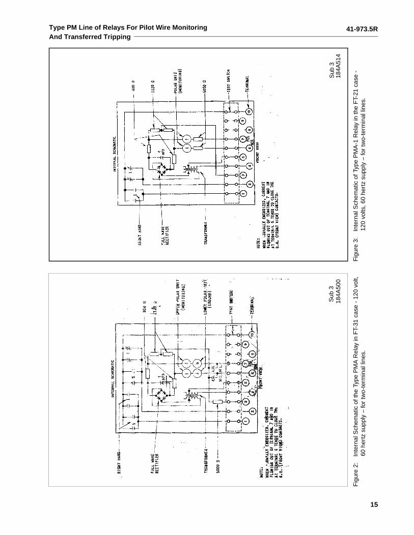
2. PMA Relay - ac supply - two terminal line - - - - - - - - - - - - - - - - - - - - - - - - - - - page 15
3. PMA-1 Relay - ac supply - two terminal line - - - - - - - - - - - - - - - - - - - - - - - - - - page 15
4. PMA Relay - ac supply - three terminal line - - - - - - - - - - - - - - - - - - - - - - - - - - - page 16
5. PMA-1 Relay - dc supply - three terminal line - - - - - - - - - - - - - - - - - - - - - - - - - - page 16
6. PMD Relay - dc supply - two terminal line - - - - - - - - - - - - - - - - - - - - - - - - - - - page 17
7. PMD-1 Relay - dc supply - two terminal line - - - - - - - - - - - - - - - - - - - - - - - - - - page 17
8. PMD Relay - dc supply - three terminal line- - - - - - - - - - - - - - - - - - - - - - - - - - - page 18
9. PMD-1 Relay - dc supply - three terminal line- - - - - - - - - - - - - - - - - - - - - - - - - - page 18
10. PM-2 Relay in FT-21 case - - - - - - - - - - - - - - - - - - - - - - - - - - - - - - - - - - - page 19
11. PM-3 Relay in FT-11 case - - - - - - - - - - - - - - - - - - - - - - - - - - - - - - - - - - - page 19
12. PM-4 Relay (auxiliary unit) - - - - - - - - - - - - - - - - - - - - - - - - - - - - - - - - - - - page 20
13. PM-5 Ground Detector Relay- - - - - - - - - - - - - - - - - - - - - - - - - - - - - - - - - - page 20
14. PM-23 Relay in FT-21 case - - - - - - - - - - - - - - - - - - - - - - - - - - - - - - - - - - page 21
15. PM-13 Relay - dc supply - two terminal line- - - - - - - - - - - - - - - - - - - - - - - - - - - page 21
16. PM-13 Relay - dc supply - three terminal line - - - - - - - - - - - - - - - - - - - - - - - - - - page 22
17. PM-13 Relay - ac supply - two or three terminal line - - - - - - - - - - - - - - - - - - - - - - page 22
18. PMG-13 Relay - dc supply - two terminal line - - - - - - - - - - - - - - - - - - - - - - - - - - page 23
19. PMG-13 Relay - dc supply - three terminal line - - - - - - - - - - - - - - - - - - - - - - - - - page 23
20. PMG-13 Relay - ac supply - two or three terminal line- - - - - - - - - - - - - - - - - - - - - - page 24
21. PMG-13 Relay - dc supply - with Telephone Relay Output - two terminal line - - - - - - - - - - page 24
22. PMG-13 Relay - dc supply - with Telephone Relay Output - three terminal line- - - - - - - - - - page 25
23. PMD Relay - dc supply - with Telephone Relay Output - two terminal line - - - - - - - - - - - - page 25
24. PMD Relay - dc supply - with Telephone Relay Output - three terminal line - - - - - - - - - - - page 26
EXTERNAL SCHEMATICS
25. PMD Relay with PM-23 or PM-4, two terminal line - - - - - - - - - - - - - - - - - - - - - - - page 27
26. PMA Relay with PM-23 or PM-4, two terminal line - - - - - - - - - - - - - - - - - - - - - - - page 28
27. dc Type PMG-13 with PM-23 or PM-4, two terminal line- - - - - - - - - - - - - - - - - - - - - page 29
28. PMD Relay with PM-23 and PM-4, three terminal line- - - - - - - - - - - - - - - - - - - - - - page 30
29. ac Type PMG-13 Relay with PM-23, two terminal line - - - - - - - - - - - - - - - - - - - - - - page 31
30. dc Type PM-13 and PM-5 with PM-23 or PM-4, two terminal line - - - - - - - - - - - - - - - - page 32
31. dc Type PM-13 Relay with PM-23 or PM-4, two terminal line - - - - - - - - - - - - - - - - - - page 33
OUTLINE AND DRILLING PLANS
32. 10 mfd capacitor - - - - - - - - - - - - - - - - - - - - - - - - - - - - - - - - - - - - - - - - page 34
33. Remote trip resistor - - - - - - - - - - - - - - - - - - - - - - - - - - - - - - - - - - - - - - page 34
34. PM-4 projection molded case - - - - - - - - - - - - - - - - - - - - - - - - - - - - - - - - - page 35
35. PM-4 semi-flush molded case - - - - - - - - - - - - - - - - - - - - - - - - - - - - - - - - - page 35
36. PM-3, PM-5 & PMD-1 in FT-11 case - - - - - - - - - - - - - - - - - - - - - - - - - - - - - - page 36
37. PM-2, PM-23, PMA-1, & PMD in FT-21 case - - - - - - - - - - - - - - - - - - - - - - - - - - page 37
38. PMA in FT-31 case- - - - - - - - - - - - - - - - - - - - - - - - - - - - - - - - - - - - - - - page 38
39. PM-13 and PMG-13 in FT-32 case - - - - - - - - - - - - - - - - - - - - - - - - - - - - - - - page 39
41-973.5R
15
Type PM Line of Relays For Pilot Wire MonitoringAnd Transferred Tripping
Fig
ure
2:In
tern
al S
chem
atic
of t
he T
ype
PM
A R
elay
in F
T-31
cas
e -
120
volt,
60 h
ertz
sup
ply
– fo
r tw
o-te
rmin
al li
nes.
Fig
ure
3:In
tern
al S
chem
atic
of T
ype
PM
A-1
Rel
ay in
the
FT-
21 c
ase
-12
0 vo
lts, 6
0 he
rtz
supp
ly –
for
two-
term
inal
line
s.
Sub
318
4A50
0S
ub 3
184A
514
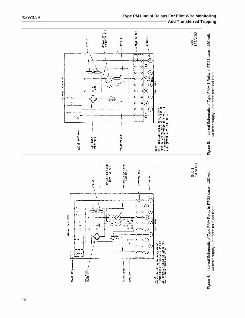
41-973.5R
16
Type PM Line of Relays For Pilot Wire MonitoringAnd Transferred Tripping
Fig
ure
4:In
tern
al S
chem
atic
of T
ype
PM
A R
elay
in F
T-31
cas
e -
120
volt,
60
her
tz s
uppl
y –
for
thre
e-te
rmin
al li
nes.
Fig
ure
5:In
tern
al S
chem
atic
of T
ype
PM
A-1
Rel
ay in
FT-
21 c
ase
- 12
0 vo
lt,
60 h
ertz
sup
ply
– fo
r th
ree-
term
inal
line
s.
Sub
118
7A19
1S
ub 1
187A
192
41-973.5R
17
Type PM Line of Relays For Pilot Wire MonitoringAnd Transferred Tripping
Fig
ure
6:In
tern
al S
chem
atic
of t
he T
ype
PM
D R
elay
in F
T-21
cas
e -
dc s
uppl
y –
for
two-
term
inal
line
s.F
igur
e 7:
Inte
rnal
Sch
emat
ic o
f the
Typ
e P
MD
-1 R
elay
in th
e F
T-11
cas
e -
dc s
uppl
y –
for
two-
term
inal
line
s.
Sub
218
4A49
7S
ub 2
184A
498
41-973.5R
18
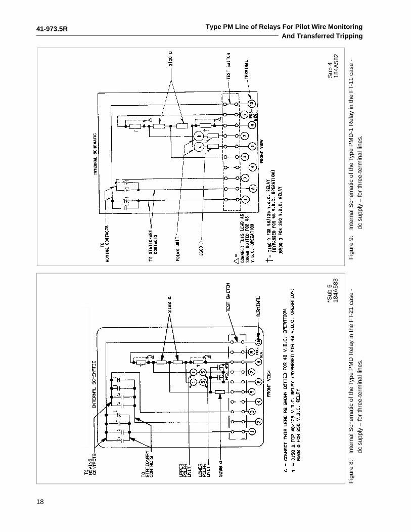
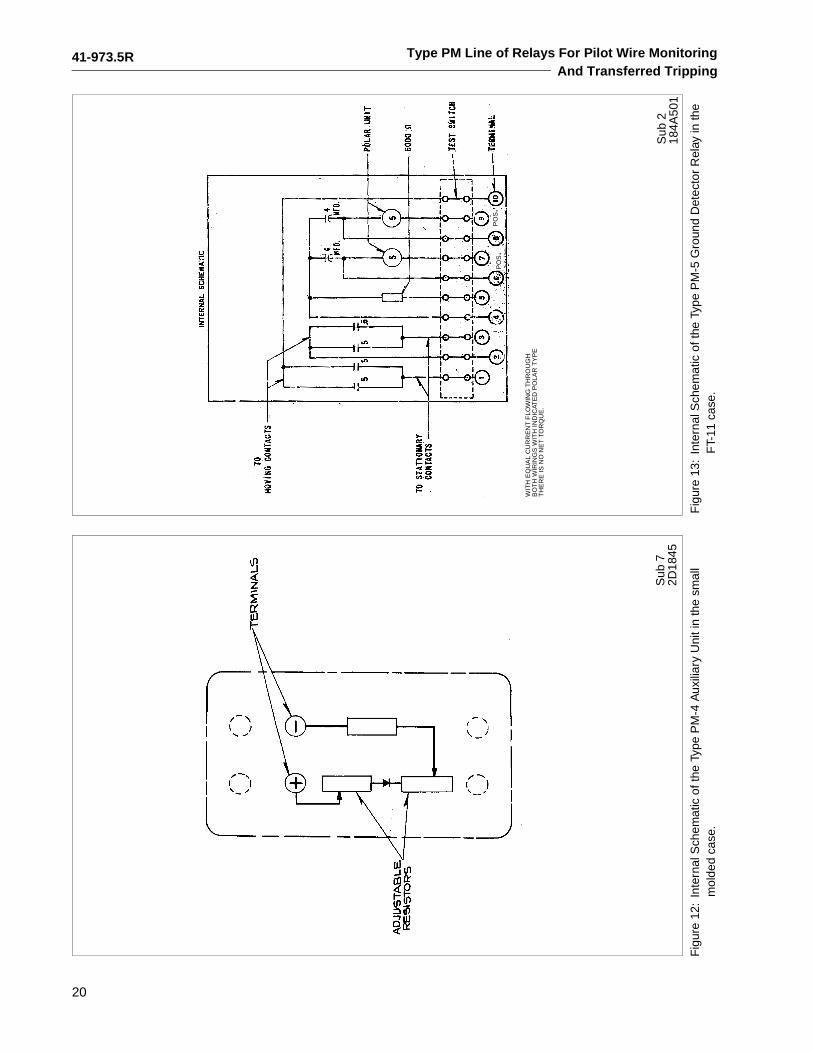
Type PM Line of Relays For Pilot Wire MonitoringAnd Transferred Tripping
Fig
ure
8:In
tern
al S
chem
atic
of t
he T
ype
PM
D R
elay
in th
e F
T-21
cas
e -
dc s
uppl
y –
for
thre
e-te
rmin
al li
nes.
Fig
ure
9:In
tern
al S
chem
atic
of t
he T
ype
PM
D-1
Rel
ay in
the
FT-
11 c
ase
-
dc s
uppl
y –
for
thre
e-te
rmin
al li
nes.
*Sub
518
4A58
3S
ub 4
184A
582
41-973.5R
19
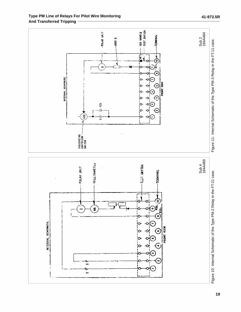
Type PM Line of Relays For Pilot Wire MonitoringAnd Transferred Tripping
Fig
ure
10:
Inte
rnal
Sch
emat
ic o
f the
Typ
e P
M-2
Rel
ay in
the
FT-
21 c
ase.
Fig
ure
11:
Inte
rnal
Sch
emat
ic o
f the
Typ
e P
M-3
Rel
ay in
the
FT-
11 c
ase.
Sub
418
4A48
9S
ub 2
184A
484
41-973.5R
20
Type PM Line of Relays For Pilot Wire MonitoringAnd Transferred Tripping
Fig
ure
12:
Inte
rnal
Sch
emat
ic o
f the
Typ
e P
M-4
Aux
iliar
y U
nit i
n th
e sm
all
mol
ded
case
.F
igur
e 13
:In
tern
al S
chem
atic
of t
he T
ype
PM
-5 G
roun
d D
etec
tor
Rel
ay in
the
FT-
11 c
ase.
Sub
72D
1845
Sub
218
4A50
1
PO
S.
PO
S.
WIT
H E
QU
AL
CU
RR
EN
T F
LOW
ING
TH
RO
UG
HB
OT
H W
IRIN
GS
WIT
H IN
DIC
ATE
D P
OLA
R T
YP
ET
HE
RE
IS N
O N
ET
TO
RQ
UE
.
41-973.5R
21
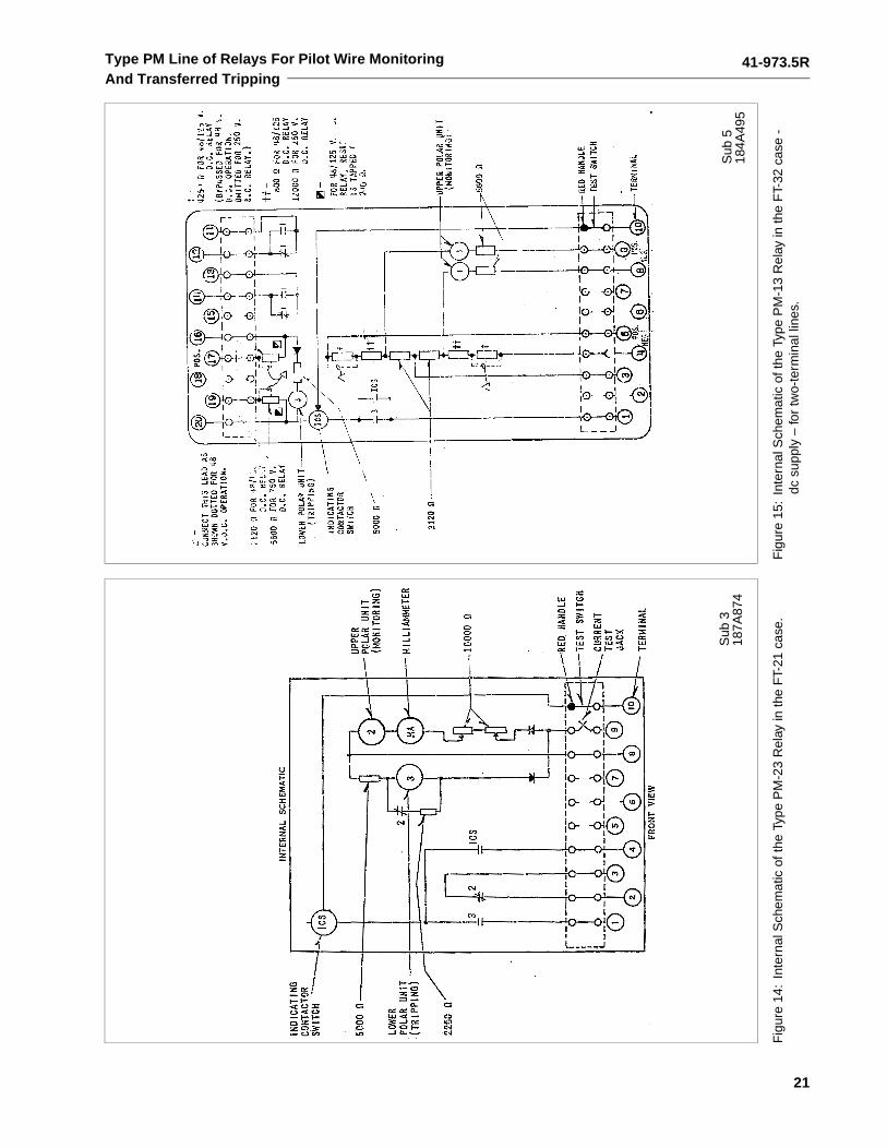
Type PM Line of Relays For Pilot Wire MonitoringAnd Transferred Tripping
Fig
ure
14:
Inte
rnal
Sch
emat
ic o
f the
Typ
e P
M-2
3 R
elay
in th
e F
T-21
cas
e.F
igur
e 15
:In
tern
al S
chem
atic
of t
he T
ype
PM
-13
Rel
ay in
the
FT-
32 c
ase
- dc
sup
ply
– fo
r tw
o-te
rmin
al li
nes.
Sub
318
7A87
4S
ub 5
184A
495
41-973.5R
22
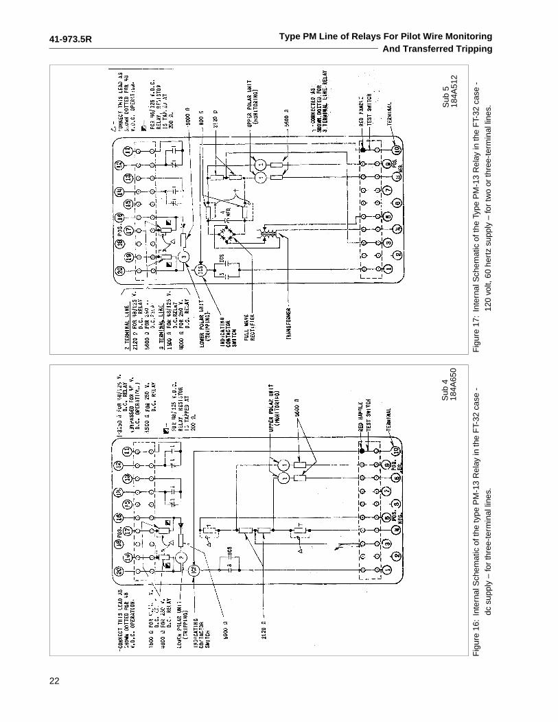
Type PM Line of Relays For Pilot Wire MonitoringAnd Transferred Tripping
Fig
ure
16:
Inte
rnal
Sch
emat
ic o
f the
type
PM
-13
Rel
ay in
the
FT-
32 c
ase
-
dc s
uppl
y –
for
thre
e-te
rmin
al li
nes.
Fig
ure
17:
Inte
rnal
Sch
emat
ic o
f the
Typ
e P
M-1
3 R
elay
in th
e F
T-32
cas
e -
120
volt,
60
hert
z su
pply
– fo
r tw
o or
thre
e-te
rmin
al li
nes.
Sub
418
4A65
0S
ub 5
184A
512
41-973.5R
23
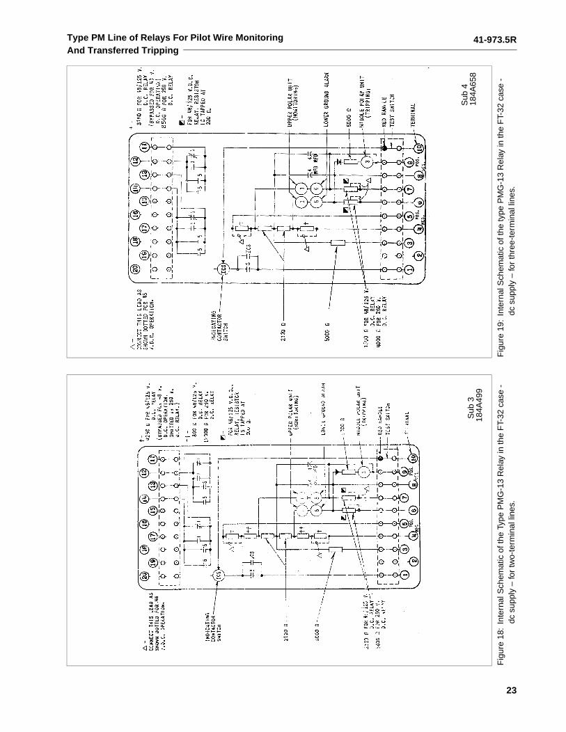
Type PM Line of Relays For Pilot Wire MonitoringAnd Transferred Tripping
Fig
ure
18:
Inte
rnal
Sch
emat
ic o
f the
Typ
e P
MG
-13
Rel
ay in
the
FT-
32 c
ase
- dc
sup
ply
– fo
r tw
o-te
rmin
al li
nes.
Fig
ure
19:
Inte
rnal
Sch
emat
ic o
f the
type
PM
G-1
3 R
elay
in th
e F
T-32
cas
e -
dc s
uppl
y –
for
thre
e-te
rmin
al li
nes.
Sub
318
4A49
9
Sub
418
4A65
8
41-973.5R
24
Type PM Line of Relays For Pilot Wire MonitoringAnd Transferred Tripping
Fig
ure
20:
Inte
rnal
Sch
emat
ic o
f the
Typ
e P
MG
-13
Rel
ay in
the
FT-
32 c
ase
- 12
0 vo
lts, 6
0 he
rtz
supp
ly –
for
two
or th
ree-
term
inal
line
s.F
igur
e 21
:P
MG
-13
Rel
ay w
ith G
roun
d A
larm
and
Rem
ote
Trip
- tw
o-te
rmin
al
lines
with
Tel
epho
ne R
elay
Out
put.
FT-
32 c
ase
Sub
418
4A51
3S
ub 1
134
90A
59
41-973.5R
25
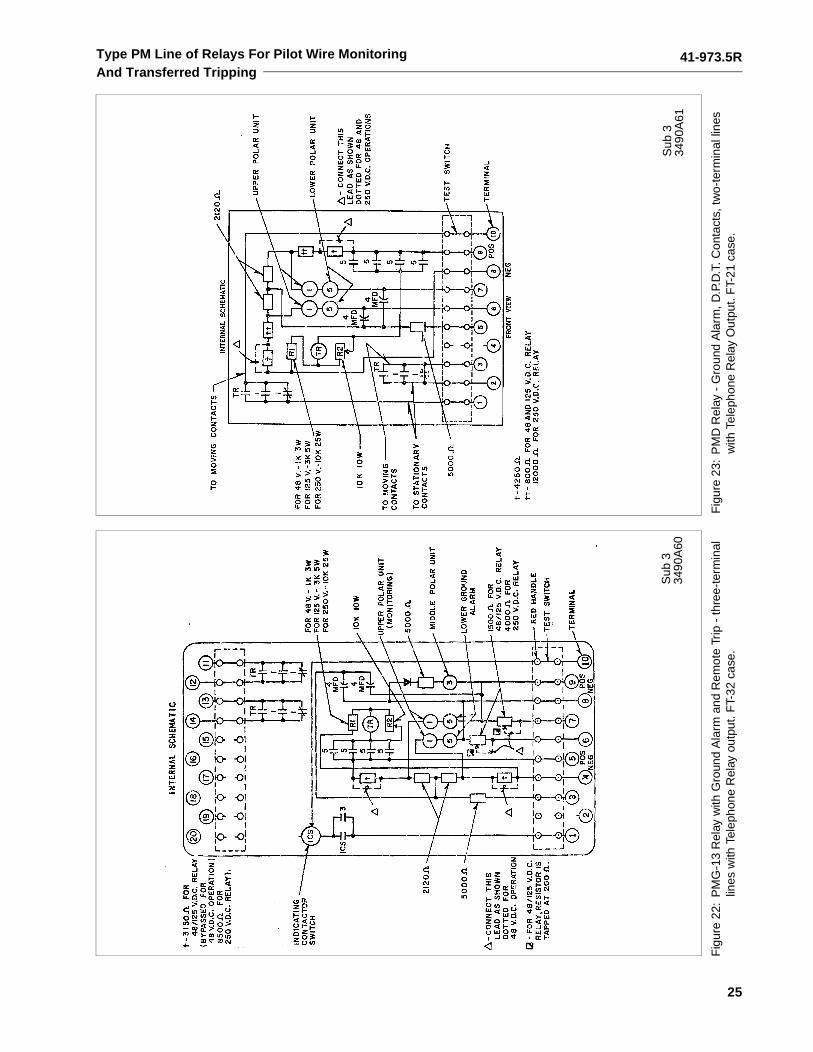
Type PM Line of Relays For Pilot Wire MonitoringAnd Transferred Tripping
Fig
ure
22:
PM
G-1
3 R
elay
with
Gro
und
Ala
rm a
nd R
emot
e Tr
ip -
thre
e-te
rmin
al
lines
with
Tel
epho
ne R
elay
out
put.
FT-
32 c
ase.
Fig
ure
23:
PM
D R
elay
- G
roun
d A
larm
, D.P
.D.T
. Con
tact
s, tw
o-te
rmin
al li
nes
with
Tel
epho
ne R
elay
Out
put.
FT-
21 c
ase.
Sub
334
90A
60S
ub 3
3490
A61
41-973.5R
26
Type PM Line of Relays For Pilot Wire MonitoringAnd Transferred Tripping
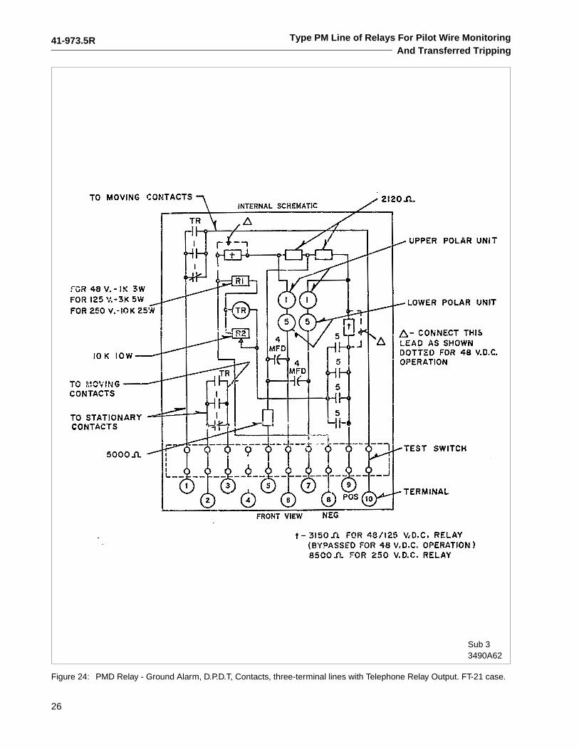
Figure 24: PMD Relay - Ground Alarm, D.P.D.T, Contacts, three-terminal lines with Telephone Relay Output. FT-21 case.
Sub 33490A62
41-973.5R
27
Type PM Line of Relays For Pilot Wire MonitoringAnd Transferred Tripping
Fig
ure
25:
Ext
erna
l Sch
emat
ic o
f the
type
PM
D R
elay
with
Typ
e P
M-2
3 or
PM
-4 R
elay
– tw
o-te
rmin
al li
nes.
*Sub
471
9B53
0
41-973.5R
28
Type PM Line of Relays For Pilot Wire MonitoringAnd Transferred Tripping
Fig
ure
26:
Ext
erna
l Sch
emat
ic o
f the
Typ
e P
MA
Rel
ay w
ith T
ype
PM
-23
or P
M-4
Rel
ay –
two-
term
inal
line
s.
*Sub
829
0B24
7
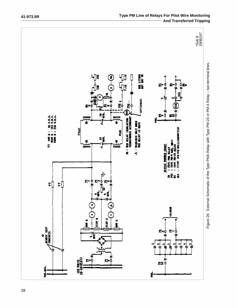
41-973.5R
29
Type PM Line of Relays For Pilot Wire MonitoringAnd Transferred Tripping
Fig
ure
27:
Ext
erna
l Sch
emat
ic o
f the
dc
Type
PM
G-1
3 R
elay
with
Typ
e P
M-2
3 or
PM
-4 R
elay
– tw
o-te
rmin
al li
nes.
* S
ub 5
719B
528
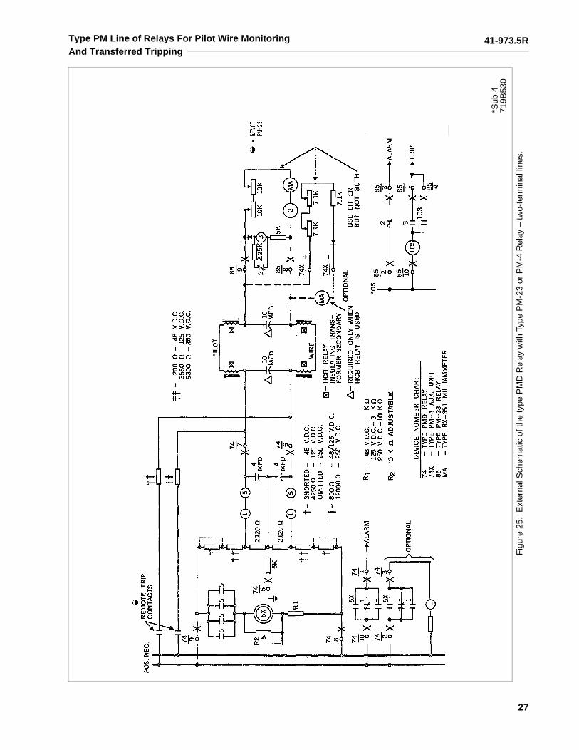
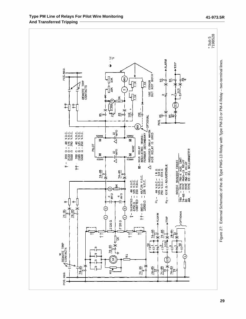
41-973.5R
30
Type PM Line of Relays For Pilot Wire MonitoringAnd Transferred Tripping
Fig
ure
28:
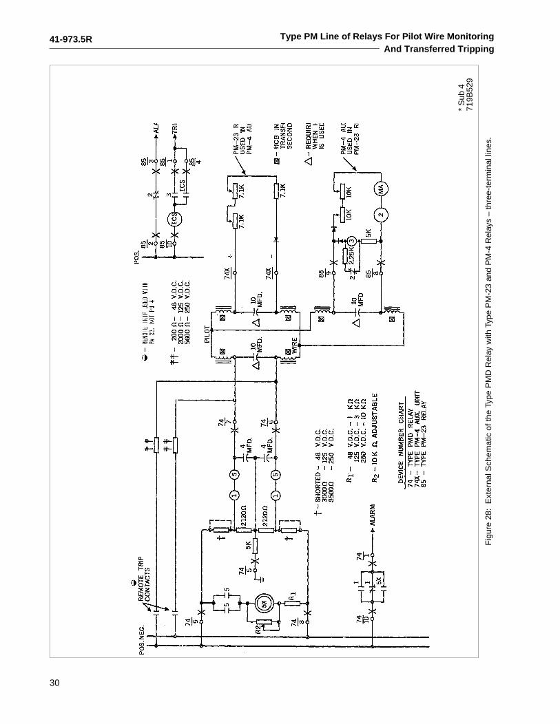
Ext
erna
l Sch
emat
ic o
f the
Typ
e P
MD
Rel
ay w
ith T
ype
PM
-23
and
PM
-4 R
elay
s –
thre
e-te
rmin
al li
nes.
* S
ub 4
719B
529
41-973.5R
31
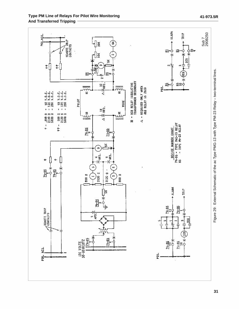
Type PM Line of Relays For Pilot Wire MonitoringAnd Transferred Tripping
Fig
ure
29:
Ext
erna
l Sch
emat
ic o
f the
ac
Type
PM
G-1
3 w
ith T
ype
PM
-23
Rel
ay –
two-
term
inal
line
s.
Sub
729
0B25
0
41-973.5R
32
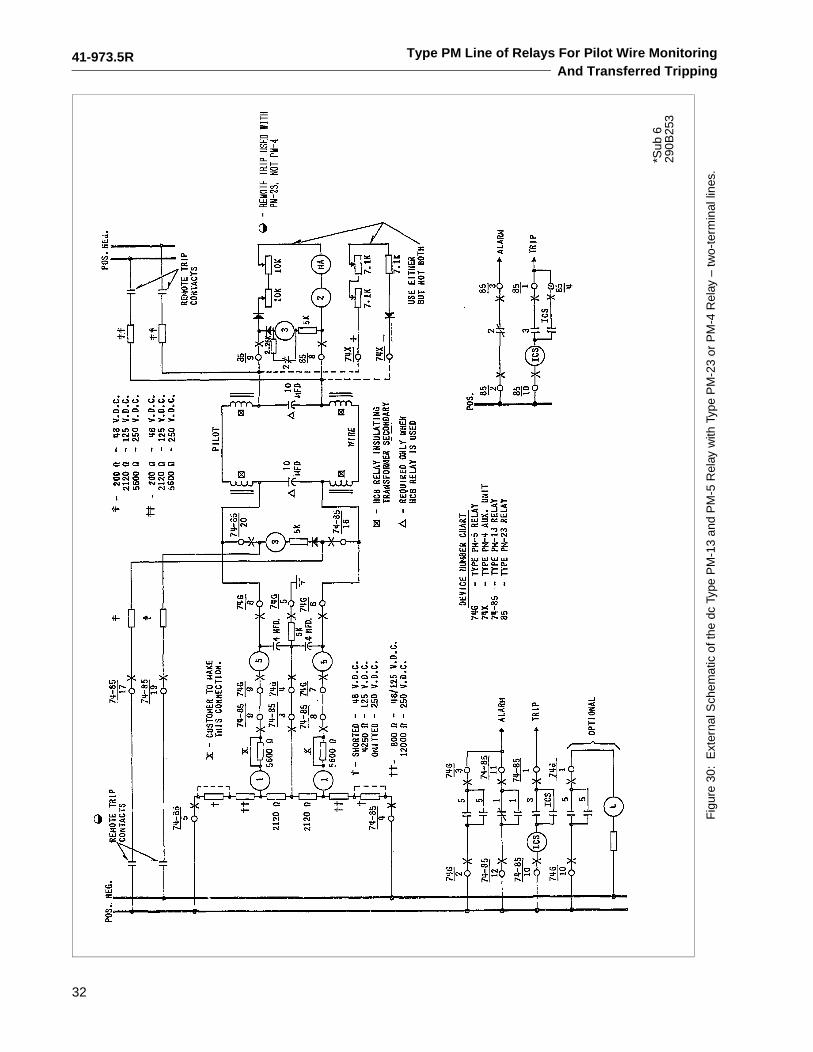
Type PM Line of Relays For Pilot Wire MonitoringAnd Transferred Tripping
Fig
ure
30:
Ext
erna
l Sch
emat
ic o
f the
dc
Type
PM
-13
and
PM
-5 R
elay
with
Typ
e P
M-2
3 or
PM
-4 R
elay
– tw
o-te
rmin
al li
nes.
*Sub
629
0B25
3
41-973.5R
33
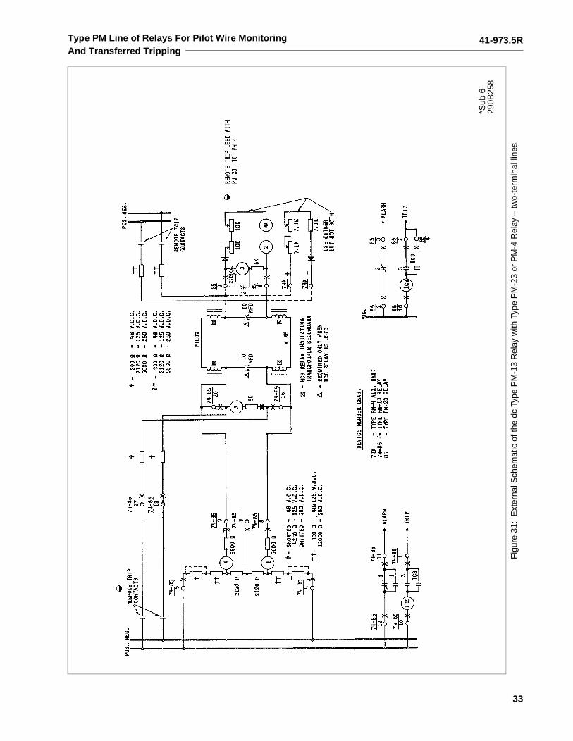
Type PM Line of Relays For Pilot Wire MonitoringAnd Transferred Tripping
Fig
ure
31:
Ext
erna
l Sch
emat
ic o
f the
dc
Type
PM
-13
Rel
ay w
ith T
ype
PM
-23
or P
M-4
Rel
ay –
two-
term
inal
line
s.
*Sub
629
0B25
8
41-973.5R
34
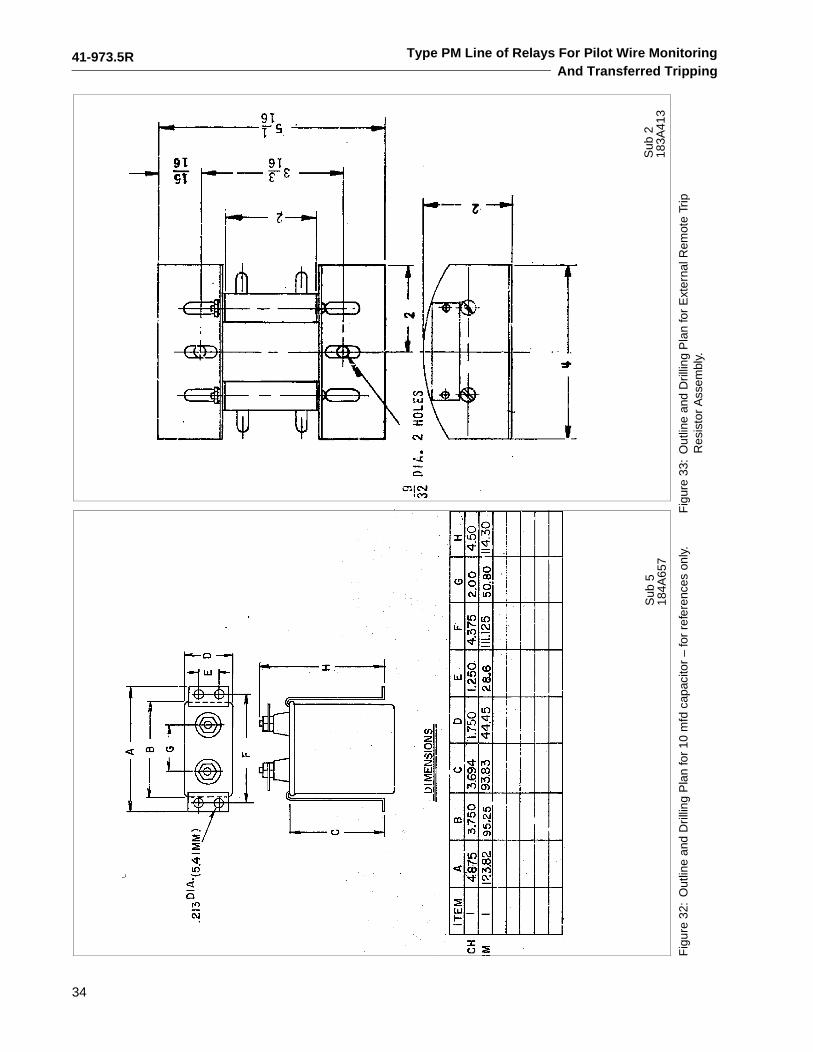
Type PM Line of Relays For Pilot Wire MonitoringAnd Transferred Tripping
Fig
ure
32:
Out
line
and
Dril
ling
Pla
n fo
r 10
mfd
cap
acito
r –
for
refe
renc
es o
nly.
Fig
ure
33:
Out
line
and
Dril
ling
Pla
n fo
r E
xter
nal R
emot
e Tr
ip
Res
isto
r A
ssem
bly.
Sub
518
4A65
7S
ub 2
183A
413
41-973.5R
35
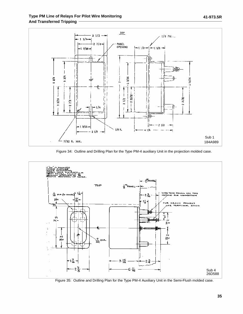
Type PM Line of Relays For Pilot Wire MonitoringAnd Transferred Tripping
Sub 1184A989
Figure 34: Outline and Drilling Plan for the Type PM-4 auxiliary Unit in the projection molded case.
Figure 35: Outline and Drilling Plan for the Type PM-4 Auxiliary Unit in the Semi-Flush molded case.
Sub 426D588
41-973.5R
36
Type PM Line of Relays For Pilot Wire MonitoringAnd Transferred Tripping
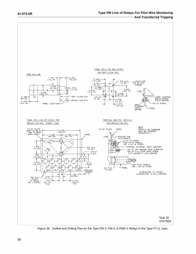
Figure 36: Outline and Drilling Plan for the Type PM-3, PM-5, & PMD-1 Relays in the Type FT-11 case.
57D7900*Sub 20
41-973.5R
37
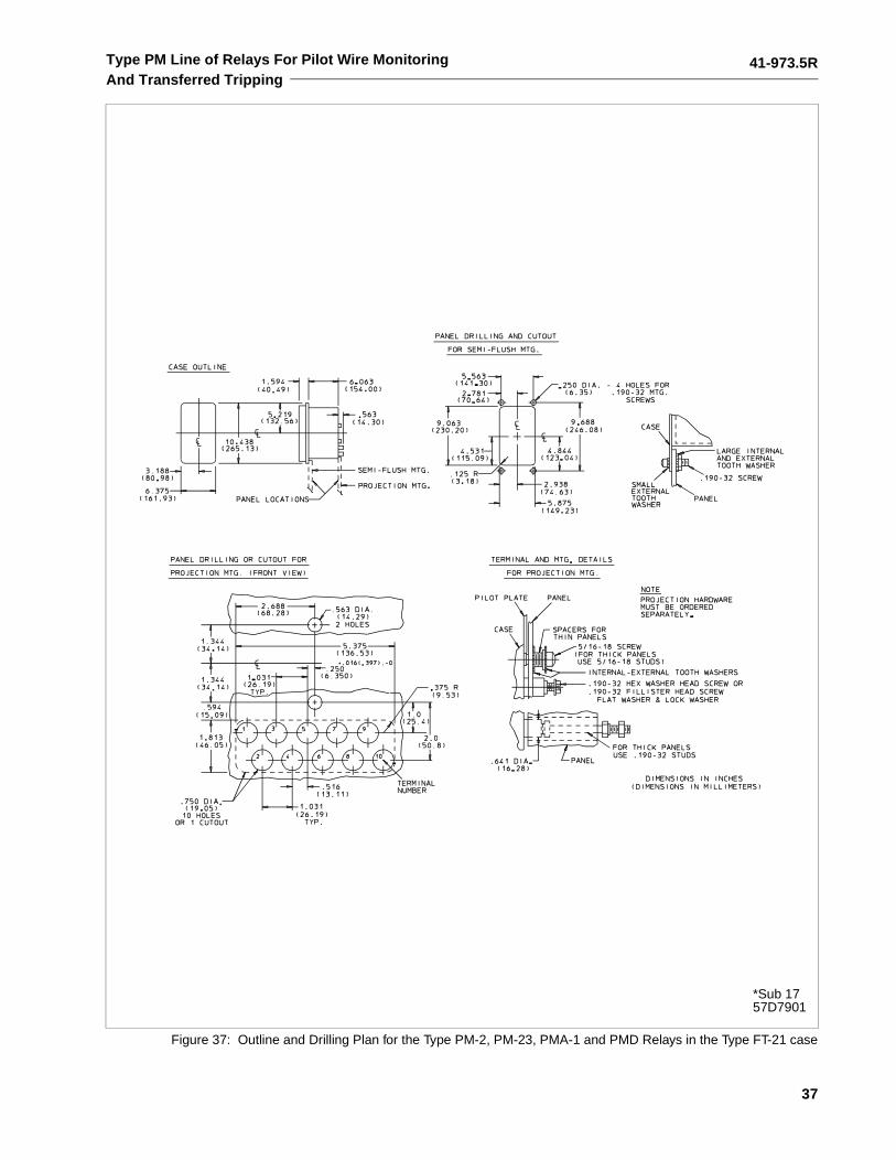
Type PM Line of Relays For Pilot Wire MonitoringAnd Transferred Tripping
Figure 37: Outline and Drilling Plan for the Type PM-2, PM-23, PMA-1 and PMD Relays in the Type FT-21 case
*Sub 1757D7901
41-973.5R
38
Type PM Line of Relays For Pilot Wire MonitoringAnd Transferred Tripping
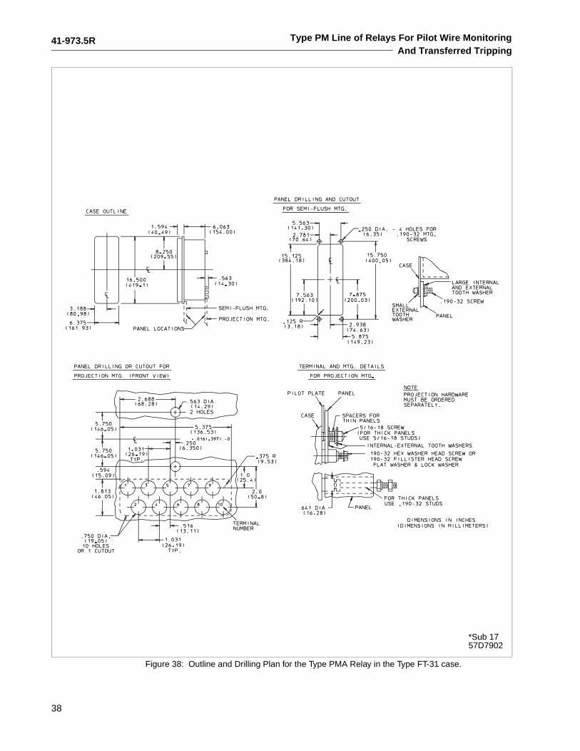
Figure 38: Outline and Drilling Plan for the Type PMA Relay in the Type FT-31 case.
*Sub 1757D7902
41-973.5R
39
Type PM Line of Relays For Pilot Wire MonitoringAnd Transferred Tripping
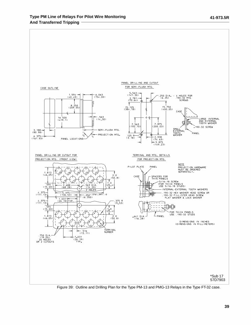
Figure 39: Outline and Drilling Plan for the Type PM-13 and PMG-13 Relays in the Type FT-32 case.
*Sub 1757D7903

ABB Inc.4300 Coral Ridge DriveCoral Springs, Florida 33065Telephone: +1 954-752-6700Fax: +1 954-345-5329www.abb.com/substation automation
IL 4
1-97
3.5
- Rev
isio
n R
ABB