Embed Size (px)
Citation preview
7/27/2019 ABB-Pilot Wire Differential Relay
http://slidepdf.com/reader/full/abb-pilot-wire-differential-relay 1/10
Page 1
Features Phase and earth fault protection for cableand overhead lines
• Protect lines with two or more terminals
• High-speed operation (1-2 cycle)
• Stability ensured for external faults• All line ends trip for fault current from single
end
• Pilot-wire voltage limited to 60 V permits
use of low cost communication wires(100V)
• 5 kV basic insulation level and 15 kV withpilot-wire isolating transformers
• 1000 ohms and 2 µF pilot-wire capacitance
• 2000 ohms and 0,7 µF with pilot-wire iso-lating transformers
• Direct trip contacts and trip flag indicator
• Test switch included
• Options:- Over current monitoring and back-up- Pilot-wire supervision
- Three-phase/+earth overcurrent back-upfunctions (3 RXIDK 2H or RXHL 401/411)- Three-phase thermal overcurrent function
(using RXHL 411)- Breaker failure current back-up function
(using RXHL 411)- Reclosing up to four shots (option withRXHL411)
Application The RADHL pilot-wire relays are used for
protection of short to medium length cable oroverhead lines. The relays use a dedicatedmetallic pilot-wire pair. The wire can be anormal low cost twisted pair communicationswire. The shield may be aluminum laminatedor copper wire type. The pilot-wire loopresistance is matched to 1000 or 2000 ohms.
The standard relay can be applied to circuitswith more than two line ends. Therefore threeor more terminal applications are possible.
The maximum length of a protected circuit isrelated to the total line charging current.The
leakage current to ground must be limited to10% of the rated primary current. The earth-
leakage current for a cable may be in the
order of 5-15A per km, depending on net-work voltage and the type and size of cable.
The most sensitive earth-fault detection of therelay is 25% of rated current. This may be fedfrom one end only, or divided between lineends.
The three-phase fault sensitivity is 72% whenfed from one end, or 36% when fed symmet-rically from two ends.
All line ends trip for a fault fed from a single-end. This makes the relay suitable for appli-
cations with weak infeed, since tripping of weak end is automatically performed.
Pilot-wire differential relayfor lines with two or moreterminals
RADHL
1MRK 507 004-BEN
Issued: March 2003Revision: A
Data subject to change without notice
Pilot-wire differential relay RADHL with RXHL 401
7/27/2019 ABB-Pilot Wire Differential Relay
http://slidepdf.com/reader/full/abb-pilot-wire-differential-relay 2/10
Pilot-wire differential relay for lines withtwo or more terminals
RADHL1MRK 507 004-BEN
Page 2
The relay is secure against power surges, out-of-step and emergency loading conditions asit uses a balanced bridge principle for mea-
surements. The operating principle offers alsothe advantage of one cycle (50/60Hz) opera-tion.RADHL versions with current level monitor-ing relays are used to avoid tripping on loadcurrent when there is an open or defectivepilot-wire. The current level monitoringrelays are also used to provide additionalrelay functions. There are three alternativestandard schemes available in the orderingtable;1. RXIDK 2H - three single phase elements.The overcurrent starting contacts providemonitoring of the differential relay tripping.
The time-overcurrent and instantaneous over-current functions provide back up to the dif-ferential relay.2. RXHL 401 - three-phase and earth over-current relay functions. Three levels of start-ing, time and instantaneous trip functions.3. RXHL 411 - three-phase and earth overcur-rent relay functions with three setting levelsfor phase and earth and thermal replica over-load, breaker failure and optional reclosingrelay functions.
Optional pilot-wire supervision provides
alarms for open, short-circuited or reversedpilot-wires.
A simple transfer trip of a remote breaker canbe obtained by opening of the RADHL’spilot-wires. The operation of the two RADHLrelays then becomes half of the normal oper-ating values, i.e. in the range 12.5 - 63 % of the CT rating, and depends on the type of thethrough going fault or load current.
Current Transformer requirementsThe CT’s at each terminal do not need to havethe same ratio. Ratio matching can be done
with auxiliary CT´s or the summation CT.The demands on the main CT’s are smallbecause the voltage in the pilot-wire circuit islimited to about 60V by zener-diodes. Theprotection is fully stable during externalfaults provided that the main CT’s areapproximately the same and the secondarylimiting e.m.f. (E2max) fulfil the requirement:
E2max ≥20 ir (RCT+RL+Z2+5/ir2) where:
For systems with high resistance earthing, the RL value is taken for a single length of the wire usedand for low resistance or solidly earthed systemsthe RL value is for the double length of the wire.
In an isolated or high impedance, resistive
earthed network main CT’s are only requiredin two phases if a separate protection is usedfor detecting earth faults.
1000/2000 Ohms & 5/15kV pilot-wires
The RADHL can operate over pilot-wireshaving 1000 ohms loop resistance, 2 µF shuntcapacitance and 5 kV difference in earth potentialbetween the terminals. The 5 kV limit can beincreased to 15 kV by an isolating transformer(ratio 1:1) at both ends. With a 15 kV transformerof ratio 1:1.7, a 2000 ohm 0,7µF pilot-wire can beused.
Multi-terminal applicationsIt is possible to use the standard RADHLrelays for lines having more than two ends.The standard relays are used with pilot-wir-padded to 500 ohms per leg. ABB providesmore details and application schematics forapplications with multi terminal lines.
ir = main CT secondary rated current
RCT = main CT secondary winding resistance
RL = resistance in the wires between the
main CT and the summation
transformer in RADHL
Z2 = impedance of other relays and loads
connected to the same CT core
7/27/2019 ABB-Pilot Wire Differential Relay
http://slidepdf.com/reader/full/abb-pilot-wire-differential-relay 3/10
Pilot-wire differential relay for lines withtwo or more terminals
RADHL1MRK 507 004-BEN
Page 3
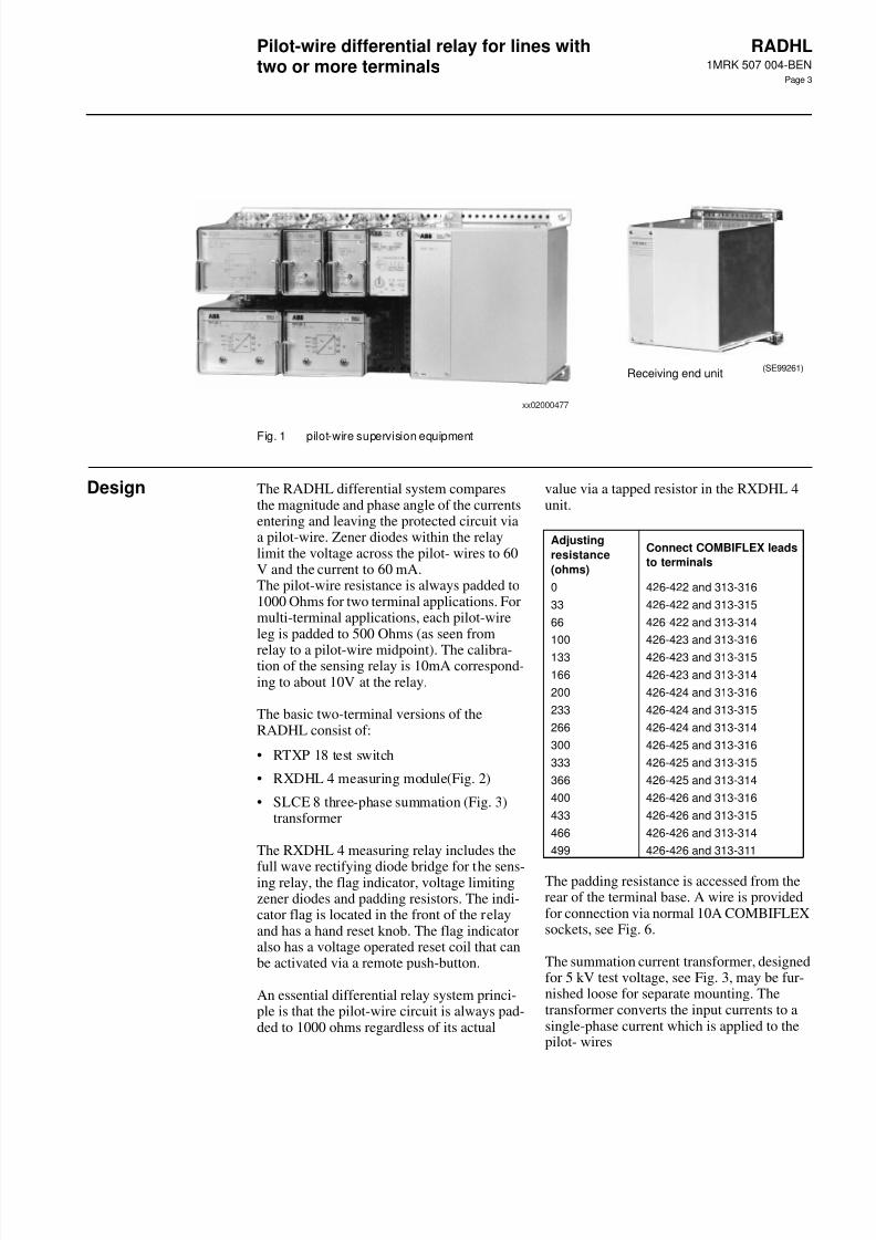
Fig. 1 pilot-wire supervision equipment
Design The RADHL differential system comparesthe magnitude and phase angle of the currentsentering and leaving the protected circuit viaa pilot-wire. Zener diodes within the relaylimit the voltage across the pilot- wires to 60V and the current to 60 mA.The pilot-wire resistance is always padded to1000 Ohms for two terminal applications. Formulti-terminal applications, each pilot-wireleg is padded to 500 Ohms (as seen from
relay to a pilot-wire midpoint). The calibra-tion of the sensing relay is 10mA correspond-ing to about 10V at the relay.
The basic two-terminal versions of theRADHL consist of:
• RTXP 18 test switch
• RXDHL 4 measuring module(Fig. 2)
• SLCE 8 three-phase summation (Fig. 3)transformer
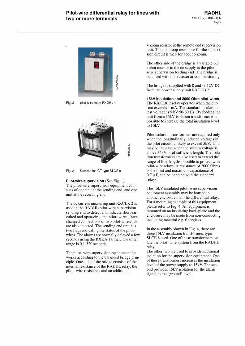
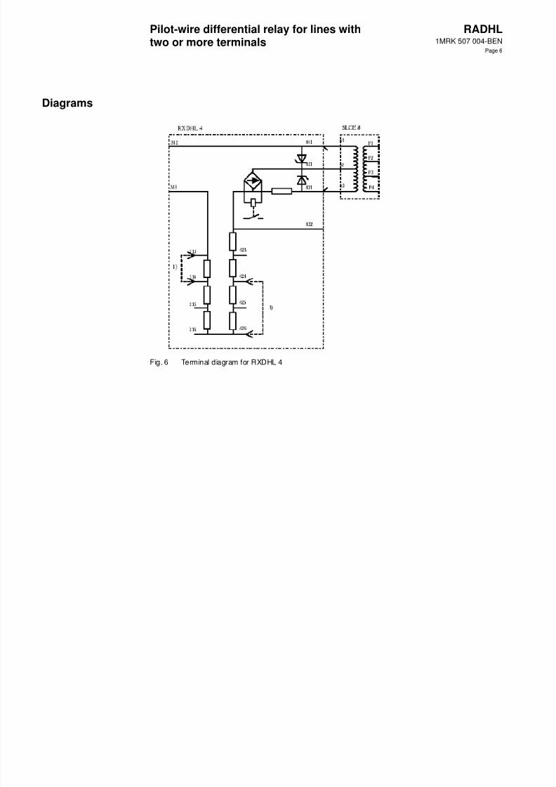
The RXDHL 4 measuring relay includes the
full wave rectifying diode bridge for the sens-ing relay, the flag indicator, voltage limitingzener diodes and padding resistors. The indi-cator flag is located in the front of the relayand has a hand reset knob. The flag indicatoralso has a voltage operated reset coil that canbe activated via a remote push-button.
An essential differential relay system princi-ple is that the pilot-wire circuit is always pad-ded to 1000 ohms regardless of its actual
value via a tapped resistor in the RXDHL 4unit.
The padding resistance is accessed from therear of the terminal base. A wire is providedfor connection via normal 10A COMBIFLEXsockets, see Fig. 6.
The summation current transformer, designedfor 5 kV test voltage, see Fig. 3, may be fur-nished loose for separate mounting. Thetransformer converts the input currents to asingle-phase current which is applied to thepilot- wires
(SE 900631)Sending end unit (SE99261)
Receiving end unit
xx02000477
Adjusting
resistance
(ohms)
Connect COMBIFLEX leads
to terminals
0 426-422 and 313-316
33 426-422 and 313-315
66 426-422 and 313-314
100 426-423 and 313-316
133 426-423 and 313-315
166 426-423 and 313-314
200 426-424 and 313-316
233 426-424 and 313-315
266 426-424 and 313-314
300 426-425 and 313-316
333 426-425 and 313-315
366 426-425 and 313-314
400 426-426 and 313-316
433 426-426 and 313-315
466 426-426 and 313-314
499 426-426 and 313-311
7/27/2019 ABB-Pilot Wire Differential Relay
http://slidepdf.com/reader/full/abb-pilot-wire-differential-relay 4/10
Pilot-wire differential relay for lines withtwo or more terminals
RADHL1MRK 507 004-BEN
Page 4
.
Fig. 2 pilot-wire relay RXDHL 4
Fig. 3 Summation CT type SLCE 8
Pilot-wire supervision (See Fig. 1)The pilot-wire supervision equipment con-sists of one unit at the sending end, and oneunit at the receiving end.
The dc current measuring unit RXCLK 2 isused in the RADHL pilot-wire supervisionsending end to detect and indicate short-cir-cuited and open-circuited pilot- wires. Inter-changed connections of two pilot-wire endsare also detected. The sending end unit hastwo flags indicating the status of the pilot-wires. The alarms are normally delayed a fewseconds using the RXKA 1 timer. The timer
range is 0,1-320 seconds.
The pilot- wire supervision equipment alsoworks according to the balanced bridge prin-ciple. One side of the bridge consists of theinternal resistance of the RADHL relay, thepilot- wire resistance and an additional
4 kohm resistor in the remote end supervisionunit. The total loop resistance for the supervi-sion circuit is therefor about 6 kohm.
The other side of the bridge is a variable 6,3kohm resistor in the dc supply at the pilot-wire supervision feeding end. The bridge isbalanced with this resistor at commissioning.
The bridge is supplied with 0 and +/-12V DCfrom the power supply unit RXTUB 2.
15kV insulation and 2000 Ohm pilot-wiresThe RXCLK 2 relay operates when the cur-rent exceeds 1 mA. The standard insulationtest voltage is 5 kV 50-60 Hz. By feeding theunit from a 15kV isolation transformer it is
possible to increase the total insulation levelto 15kV.
Pilot isolation transformers are required onlywhen the longitudinally induced voltages inthe pilot circuit is likely to exceed 5kV. Thismay be the case when the system voltage isabove 36kV or of sufficient length. The isola-tion transformers are also used to extend therange of line-lengths possible to protect withpilot-wire relays. A resistance of 2000 Ohmsis the limit and maximum capacitance of 0.7 µ F, can be handled with the standardrelays.
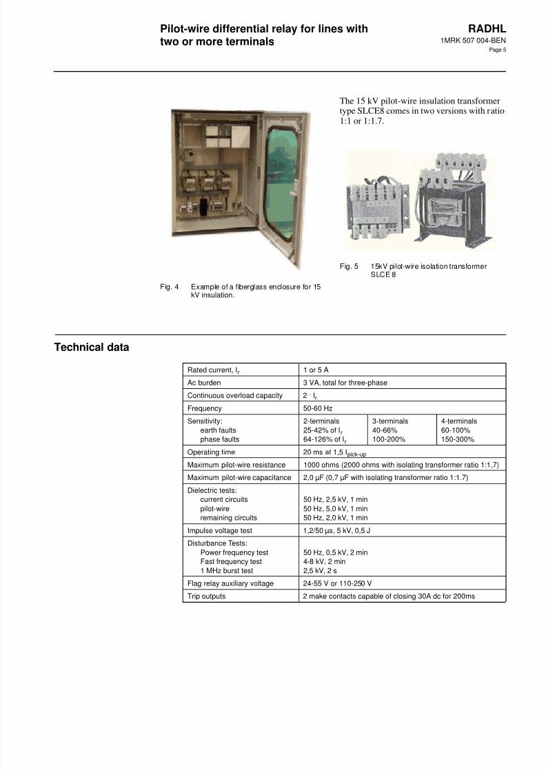
The 15kV insulated pilot- wire supervisionequipment assembly may be housed inanother enclosure than the differential relay.For a mounting example of this equipment,please refer to Fig. 4. All equipment ismounted on an insulating back-plane and theenclosure may be made from non-conductinginsulating material e.g. fiberglass.
In the assembly shown in Fig. 4, there arethree 15kV insulation transformers typeSLCE 8 used. One of these transformers iso-
late the pilot- wire system from the RADHLrelay.The other two are used to provide additionalisolation for the supervision equipment. Oneof these transformers increases the insulationlevel of the power supply to 15kV. The sec-ond provides 15kV isolation for the alarmsignal to the "ground" level.
( X X 0 2 0 0 0 5 2 7 )
( S E 9 7 0 8 6 8 )
7/27/2019 ABB-Pilot Wire Differential Relay
http://slidepdf.com/reader/full/abb-pilot-wire-differential-relay 5/10
Pilot-wire differential relay for lines withtwo or more terminals
RADHL1MRK 507 004-BEN
Page 5
Fig. 4 Example of a fiberglass enclosure for 15kV insulation.
The 15 kV pilot-wire insulation transformertype SLCE8 comes in two versions with ratio1:1 or 1:1.7.
Fig. 5 15kV pilot-wire isolation transformerSLCE 8
Technical data
Rated current, Ir 1 or 5 A
Ac burden 3 VA, total for three-phase
Continuous overload capacity 2 . Ir
Frequency 50-60 Hz
Sensitivity:
earth faults
phase faults
2-terminals
25-42% of Ir
64-126% of Ir
3-terminals
40-66%
100-200%
4-terminals
60-100%
150-300%
Operating time 20 ms at 1,5 Ipick-up
Maximum pilot-wire resistance 1000 ohms (2000 ohms with isolating transformer ratio 1:1,7)
Maximum pilot-wire capacitance 2,0 µF (0,7 µF with isolating transformer ratio 1:1.7)
Dielectric tests:
current circuits
pilot-wire
remaining circuits
50 Hz, 2,5 kV, 1 min
50 Hz, 5,0 kV, 1 min
50 Hz, 2,0 kV, 1 min
Impulse voltage test 1,2/50 µs, 5 kV, 0,5 J
Disturbance Tests:Power frequency test
Fast frequency test
1 MHz burst test
50 Hz, 0,5 kV, 2 min
4-8 kV, 2 min
2,5 kV, 2 s
Flag relay auxiliary voltage 24-55 V or 110-250 V
Trip outputs 2 make contacts capable of closing 30A dc for 200ms
7/27/2019 ABB-Pilot Wire Differential Relay
http://slidepdf.com/reader/full/abb-pilot-wire-differential-relay 6/10
Pilot-wire differential relay for lines withtwo or more terminals
RADHL1MRK 507 004-BEN
Page 6
Diagrams
Fig. 6 Terminal diagram for RXDHL 4
7/27/2019 ABB-Pilot Wire Differential Relay
http://slidepdf.com/reader/full/abb-pilot-wire-differential-relay 7/10
Pilot-wire differential relay for lines withtwo or more terminals
RADHL1MRK 507 004-BEN
Page 7
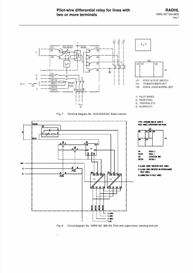
Fig. 7 Terminal diagram No. 7434 209-EAA. Basic version.
Fig. 8 Circuit diagram No. 1MRK 001 358-AA. Pilot-wire supervision, sending end unit.
.
125:211
125:212
125:213
125:114
4A
5A
6A
1013A9A
10A
101 RADHL7434 209-EA
3)
4)
2) (+)
(-)
+ +
+
-
UL
-
2 A
1 0 1
1 A
1 8 A
d
17A
101
1)
L1(R)
L2(S)
L3(T)
d
36C
4U
101 107 125
RESETFLAG
101 RTXP 18 TEST SWITCH
107 TRANSFORMER UNIT
125 RXDHL 4 MEASURING UNIT
1) PILOT-WIRES
2) RESETTING
3) TRIPPING ETC.
4) ALARM ETC.
7/27/2019 ABB-Pilot Wire Differential Relay
http://slidepdf.com/reader/full/abb-pilot-wire-differential-relay 8/10
Pilot-wire differential relay for lines withtwo or more terminals
RADHL1MRK 507 004-BEN
Page 8
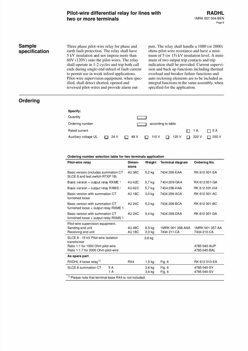
Samplespecification
Three phase pilot-wire relay for phase andearth fault protection. The relay shall have5 kV insulation and not impose more than
60V (120V) onto the pilot-wires. The relayshall operate in 1-2 cycles and trip both callends during single-end infeed of fault currentto permit use in weak infeed applications.Pilot-wire supervision equipment, when spec-ified, shall detect shorted, opened andreversed pilot-wires and provide alarm out-
puts. The relay shall handle a 1000 (or 2000)ohms pilot-wire resistance and have a mini-mum of 5 (or 15) kV insulation level. A mini-
mum of two output trip contacts and tripindication shall be provided. Current supervi-sion and back up functions including thermaloverload and breaker failure functions andauto reclosing elements are to be included asintegral functions in the same assembly, whenspecified for the application.
Ordering
Specify:
Quantity
Ordering number according to table
Rated current 1 A 5 A
Auxiliary voltage UL 24 V 48 V 110 V 125 V 220 V 250 V
Ordering number selection table for two terminals application
Pilot-wire relay Dimen-
sions
Weight Terminal diagram Ordering No.
Basic version (includes summation CT
SLCE 8 and test switch RTXP 18)
4U 36C 5,2 kg 7434 209-EAA RK 612 001-EA
Basic version + output relay RXME 1 4U 42C 5,7 kg 7434 209-GAA RK 612 001-GA
Basic version + output relay RXMS 1 4U 42C 5,7 kg 7434 209-HAA RK 612 001-HA
Basic version with summation CT
furnished loose
4U 18C 3,0 kg 7434 209-ACA RK 612 001-AC
Basic version with summation CT
furnished loose + output relay RXME 1
4U 24C 5,3 kg 7434 209-BCA RK 612 001-BC
Basic version with summation CT
furnished loose + output relay RXMS 1
4U 24C 5,4 kg 7434 209-DAA RK 612 001-DA
Pilot-wire supervision equipment:
Sending end unit
Receiving end unit
4U 48C
4U 18C
6,5 kg
2,0 kg
1MRK 001 358-AAA
7434 211-CA
1MRK 001 357-AA
7434 210-CA
SLCE 8 - 15 kV Pilot-wire isolation
transformer
Ratio 1:1 for 1000 Ohm pilot-wireRatio 1:1,7 for 2000 Ohm pilot-wire
3,6 kg
4785 040-AUP4785 040-BAL
As spare part
RXDHL 4 loose relay1) RX4 1,5 kg Fig. 6 RK 612 010-EA
SLCE 8 summation CT 5 A
1 A
3,6 kg
3,6 kg
Fig. 6
Fig. 6
4785 040-SY
4785 040-SV
1) Please note that terminal base RX4 is not included.
7/27/2019 ABB-Pilot Wire Differential Relay
http://slidepdf.com/reader/full/abb-pilot-wire-differential-relay 9/10
Pilot-wire differential relay for lines withtwo or more terminals
RADHL1MRK 507 004-BEN
Page 9
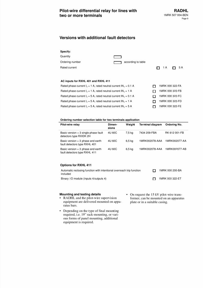
Versions with additional fault detectors
Mounting and testing details• RADHL and the pilot-wire supervision
equipment are delivered mounted on appa-ratus bars.
• Depending on the type of final mountingrequired, i.e. 19” rack-mounting, or vari-ous forms of panel mounting, additionalequipment is required.
• On request the 15 kV pilot-wire trans-former, can be mounted on an apparatus
plate or in a suitable casing.
Specify:
Quantity
Ordering number according to table
Rated current 1 A 5 A
AC inputs for RXHL 401 and RXHL 411
Rated phase current Ir = 1 A, rated neutral current INr = 0.1 A 1MRK 000 322-FA
Rated phase current Ir = 1 A, rated neutral current INr = 1 A 1MRK 000 322-FB
Rated phase current Ir = 5 A, rated neutral current INr = 0.1 A 1MRK 000 322-FC
Rated phase current Ir = 5 A, rated neutral current INr = 1 A 1MRK 000 322-FD
Rated phase current Ir = 5 A, rated neutral current INr = 5 A 1MRK 000 322-FE
Ordering number selection table for two terminals application
Pilot-wire relay Dimen-
sions
Weight Terminal diagram Ordering No.
Basic version + 3 single phase fault
detectors type RXIDK 2H
4U 60C 7,5 kg 7434 209-FBA RK 612 001-FB
Basic version + 3 phase and earth
fault detectors type RXHL 401
4U 60C 6,5 kg 1MRK002078-AAA 1MRK002077-AA
Basic version + 3 phase and earth
fault detectors type RXHL 411
4U 60C 6,5 kg 1MRK002078-AAA 1MRK002077-AB
Options for RXHL 411
Automatic reclosing function with intentional overreach trip function
included
1MRK 000 200-BA
Binary I/O module (inputs 4/outputs 4) 1MRK 000 322-ET
7/27/2019 ABB-Pilot Wire Differential Relay
http://slidepdf.com/reader/full/abb-pilot-wire-differential-relay 10/10
Pilot-wire differential relay for lines withtwo or more terminals
RADHL1MRK 507 004-BEN
Page 10
Reference RADHL Users guideCOMBIFLEX mounting hardware detailsCOMBITEST test equipment details
RXIDK 2H current monitoring relayRXHL 401current monitoring relayRXHL 411current monitoring relayRXME 1 intertrip auxiliary relayRXMS 1 intertrip auxiliary relay
1MRK 507 004-UEN1MRK 513 003-BEN1MRK 512 001-BEN
1MRK 509 002-BEN1MRK 509 062-BEN1MRK 509 049-BEN1MRK 508 015-BEN1MRK 508 015-BEN
Manufacturer ABB Automation Technology Products AB
Substation Automation
SE-721 59 Västerås
Sweden
Telephone +46 (0) 21 34 20 00
Facsimile +46 (0) 21 14 69 18
Internet: www.abb.com/substationautomation