Embed Size (px)
Citation preview

RADHLMulti-terminal Pilot-Wire Differential Relay
• Phase and earth fault protection for cables and overhead lines
• Protects feeders with 2, 3 and up to 4-terminals
• High speed of operation: 20 - 40 ms depending on number of termi-nals and CT data
• Stability ensured for external faults
• All line terminals trip, even with fault current fed from single input terminal
• A simple transfer-trip can be obtained by opening of pilot-wires
• Pilot-wire voltage limited to about 60 V by zener diodes
• Permits the use of low cost 60 V communication type copper pilot-wires
• Relay with standard 5 kV insulation level to ground
• For pilots > 10 km, close to power cables, 15 kV isolating transform-ers are available
• Standard pilot-wire loop resistance 1000 ohm and 2 µF of inter-core capacitanc
• With direct trip contacts and flag indicator (auxiliary trip relay not required)
• Test switch RTXP 18 is included
• Options with 3-phase over-current and earth-fault starting relays:RXIDK 2H, RXHL 401 /411 (with thermal, breaker failure and reclos-ing)
Features
User’s guide1MRK 507 004-UENRevision: BIssued March 2005
Data subject to changewithout notice
RADHL with RXHL 401


COPYRIGHT
WE RESERVE ALL RIGHTS TO THIS DOCUMENT, EVEN IN THE EVENT THAT A PATENT IS ISSUED AND A DIFFERENT COM-MERCIAL PROPRIETARY RIGHT IS REGISTERED. IMPROPER USE, IN PARTICULAR REPRODUCTION AND DISSEMINATION TO THIRD PARTIES, IS NOT PERMITTED.
THIS DOCUMENT HAS BEEN CAREFULLY CHECKED. HOWEVER, IN CASE ANY ERRORS ARE DETECTED, THE READER IS KINDLY REQUESTED TO NOTIFY THE MANUFACTURER AT THE ADDRESS BELOW.
THE DATA CONTAINED IN THIS MANUAL IS INTENDED SOLELY FOR THE CONCEPT OR PRODUCT DESCRIPTION AND IS NOT TO BE DEEMED TO BE A STATEMENT OF GUARANTEED PROPERTIES. IN THE INTERESTS OF OUR CUSTOMERS, WE CONSTANTLY SEEK TO ENSURE THAT OUR PRODUCTS ARE DEVELOPED TO THE LATEST TECHNOLOGICAL STAN-DARDS. AS A RESULT, IT IS POSSIBLE THAT THERE MAY BE SOME DIFFERENCES BETWEEN THE HW/SW PRODUCT AND THIS INFORMATION PRODUCT.

RADHLMulti-terminal Pilot-Wire Differential Relay
1MRK 507 004-UENPage 4
TABLE OF CONTENTS
1 APPLICATION ...........................................................................62 CURRENT TRANSFORMER REQUIREMENT....................7
3 TYPE OF PILOT WIRES ..........................................................8
4 MECHANICAL DESIGN...........................................................9
5 PILOT WIRE PADDING RESISTOR SETTINGS...............10
6 PRINCIPLES OF OPERATION .............................................11
6.1 Auxiliary sum-CT............................................................116.1.1 Auxiliary sum-CT ...................................................116.1.2 Relay operating equation.........................................116.1.3 Relay operating current ...........................................12
6.2 2-Terminals: normal load current .................................136.2.1 Normal load voltage diagram..................................146.2.2 Fault current distribution.........................................146.2.3 Fault voltage diagram..............................................15
6.3 4-Terminals: normal load current .................................166.3.1 Normal load voltage diagram..................................176.3.2 Fault current distribution.........................................176.3.3 Fault voltage diagram..............................................18
7 INTERTRIPPING .....................................................................19
7.1 Opening pilot-wires .........................................................19
8 PILOT-WIRE SUPERVISION ................................................21
8.1 Faulty pilot-wire ..............................................................21
8.2 Pilot-wire dc loop circuit.................................................22
8.3 Unbalance.........................................................................23
9 COMMISSIONING...................................................................24
9.1 Equipment required ........................................................24
9.2 Test procedure .................................................................24
9.3 CT polarity check ............................................................25
9.4 Pilot-wire supervision (PWS) .........................................26

1MRK 507 004-UENPage 5
RADHLMulti-terminal Pilot-Wire Differential Relay
10 TECHNICAL DATA ................................................................ 27
11 ORDERING ............................................................................... 28
11.1 Versions with additional fault detectors ....................... 2911.1.1 Mounting and testing details................................... 29
12 REFERENCE ............................................................................ 40
13 MANUFACTURER .................................................................. 40

RADHLMulti-terminal Pilot-Wire Differential Relay
1MRK 507 004-UENPage 6
1 APPLICATION
The standard RADHL may be used in low- and high- voltage networks, toprotect overhead lines and cables, with 2- and up to 4-terminal ends. Ded-icated metallic plot-wires are required between all terminal ends. With 3-and 4-terminals, one central terminal will be selected as the electrical midpoint (EMP), and the pilot-wire loop resistance up to this point may be500 ohms.The permissible maximum length of the primary line or cable is related tothe capacitive charging current. With an earth fault externally to the pro-tected feeder, a so-called earth-leakage current will enter the feeder andappear to be an internal fault quantity. This must be limited to < 10 % ofthe main CT rating.
The earth-leakage current of a cable may be 2 - 6 A per km, depending onnetwork voltage and type of cable.
The most sensitive earth-fault operating current is in the range: 25 - 55 %of the CT rating, and depends on the number of terminals. This operatingcurrent may be fed from one end only, or divided between line ends. Forthe 2-terminal scheme the 3-phase operating current is 72 % when fedfrom one end, i.e. 36 % when fed symmetrically from two ends.
The stability of the relay is based partly on the well-known high imped-ance theory and the fact that the (RXID) measuring relays at all line endsare situated at a so called electrical mid-point (EMP). At these points thevoltage will be zero at through going loads and through faults. The intro-duction of the voltage limiting zener diodes at all ends make the relaymore stable in the event of heavy through faults with risk of CT saturation.When the magnitude of the through fault current increases, the zenerdiodes start to draw more current. The unbalance current required to causerelay operation is thereby increased and the stability of the relayingscheme is improved.
Broken, or opened, pilot-wires will cause the RADHL to mal operate ifthe through going load current is more than 36 % of the CT rating. Thisrisk of mal operation can be prevented by including so called over-currentstarting relays. Three RXIDK 2H, single phase over current relays, may beinstalled in the phase wires on the primary side of the auxiliary summationCT. Tripping of the circuit breaker at that end will then be dependent onthe over current and time delay settings selected on the RXIDK (see dia-gram 7434 209-FB). Other feeder relays with a number of special featuresmay also be considered, e.g. RXHL 401/ 411 (see Section 12).
Optional pilot-wire supervision may be installed to provide alarm foropen, short-circuited and cross-connected pilots.
A simple transfer-trip, of a remote breaker, can be obtained by opening theRADHL's pilot-wires. The operation the 2-terminal RADHL relay thenbecomes half of the normal operating values, i.e. in the range: 12.5 - 63 %of the CT rating.

1MRK 507 004-UENPage 7
RADHLMulti-terminal Pilot-Wire Differential Relay
2 CURRENT TRANSFORMER
The main CT's at the feeder ends need not have the same ratios, becauseratio matching can be made in a specially ordered aux sum CT, SLCE 8.The line ends with the smaller ratio will have the standard aux sum-CT (1A or 5 A), and the other end(s) with a higher ratio will have the specialaux sum-CT.
The protection is fully stable during external faults provided the main CT'shave a secondary e.m.f. equal to or more than:
E2 = 20 *ir (RCT + RL + Z2 + 5/ ir 2 ) where:ir = main CT secondary current RCT = main CT secondary winding resistanceRL = 1-way wire resistance up to RADHLZ2 = impedance of other relays
Note:In systems with the neutral solidly grounded, the RL should include the 2-way resistance value.
The main CT's at the feeder ends must also be of the same class (e.g.5P20, 10 VA), and they must have similar secondary burden, i.e. pilot-wire lengths and the same type of other (extra) relays, if included. Particu-larly if the other relays are of the old type with a high burden. If an extraburden is included at one end only, a certain unbalance of will be created.This may be seen as a small unbalance voltage (e.g. 0.1 - 1 V ac) acrosseach measuring diff relay during normal full load.
Example of required knee-point voltage for typical main CT with 5 A secrating.
ir = 5 ARCT = 0.3 ohms (e.g. 600 / 5 A)RL = 0.1 ohm (e.g. 20 meter loop 4 mm2)Z2 = 0 (no extra relay)5/25 = 0.2 ohms (burden of RADHL)Hence:E2 = 20 * 5 A (0.3 + 0.1 + 0 + 0.2) = 60 V
A main CT with a standard class: 5P20, 10 VA (10 VA /52 =0.4 ohms) andRCT = 0.3 ohms will produce: E2 = 100 A * (0.3 + 0.4) = 70 V, which willbe more than adequate.
In some cases the main CT's may comprise two cores of different ironarea. By series connecting the secondaries of these cores the total second-ary output emf will be increased and in most cases give a better overallknee-point voltage value. We suggest that this possibility be checked incase of stability problem.
REQUIREMENT
RADHLMulti-terminal Pilot-Wire Differential Relay
1MRK 507 004-UENPage 8
3 TYPE OF PILOT WIRES
The typical 2-terminal RADHL can operate over pilot-wires having 1000ohms of loop resistance and 2 µF of shunt capacitance. With the 3- and 4-terminal RADHL, one of the middle terminals must be selected as theEMP (electrical-mid point). The padding resistor of the relay at the EMPmust be set at the max value of 500 ohms. For all the other relay terminals,the pilot-wire loop-resistance up to the EMP may be max 500 ohms (seeFig. 14).By including a special pilot-wire isolating transformer (see Fig. 1) withturns-ratio 1: 1.7 t, the pilot-wire loop-resistance for the 2-terminal relaymay be increased to 2000 ohms, but the permissible inter-core capacitanceis reduced to 0.7 uF. With the 3- and 4-terminal relay the loop-resistanceup to the EMP may be 1000 ohms and inter-core capacitance 0.7 uF. Oneisolating transformer is required at each relay terminal.
The pilot-wires may be of the telephone, communication type, with ratedvoltage 60 V, and with cores twisted into pairs. A common screen, or indi-vidually screened pairs, will protect against external interference. Thescreen may be of aluminium or copper wires and should be grounded atboth ends.
When a pilot-wire cable is laid in parallel with a high voltage power cable,it may be subjected to induced voltages between each core and the screen(ground), which can be much higher than the rated voltage between cores(limited to 60 V).
The RADHL has standard insulation strength to ground of 5 kV, which inthe majority of installations is more than adequate. However, in some spe-cial cases, with very long pilot cables > 10 km, an isolating auxiliarytransformer may be installed at all relay ends. This will keep the pilot-wires isolated from ground, and from the relay circuit, by an insulationlevel of 15 kV. Thus, no dangerous induced voltages in the pilots shouldbe able to reach the relay and cause a flashover to ground.
Fig. 1 15kV pilot-wire isolation transformer SLCE 8
(xx02000473.tif)

1MRK 507 004-UENPage 9
RADHLMulti-terminal Pilot-Wire Differential Relay
Fig.
4 MECHANICAL DESIGN
The RADHL pilot-wire differential relay is installed in the Combiflex sys-tem of relay mounting (see 1MRK 513 003-BEN). It includes a test switchRTXP 18, an auxiliary summation CT type SLCE 8, and a main plug in 4-seat relay unit RXDHL 4. The RADHL diff relay is available in two dif-ferent designs. The aux sum-CT may be included in the standard relayframe, or it may be supplied loose for mounting separately in the rear ofthe relay cubicle.The RTXP 18 test switch enables easy testing of each RADHL relay (see 1MRK 512 001-BEN). The RXDHL 4 unit includes the internalmeasuring relay (Re), which is fed via a full-wave rectifier. This rectifieris connected between: the mid point of the aux sum-CT secondary wind-ing, and the internal padding resistor. The dc-operating burden of the Re-relay is about:
10 mA * 10 V = 100 mW.
The RADHL 4 unit also includes the zener diodes, a fixed 500 ohms resis-tor, the adjustable 33 - 499 ohms padding resistor and a red flag indicator.This flag is seen at the front of the unit and can be manually reset, or elec-trically via a remote (external) push button:
The basic version of the RADHL pilot-wire diff relay consists of:
• 1- RTXP 18, test switch• 1 - RADHL 4, measuring module (see Fig. 2)• 1 - SLCE 8, auxiliary summation CT (see Fig. 3)
Additional plug in units to be ordered separately as required:
• 1 -RXME 1 tripping relay with heavy duty contacts• 1 - RXMS 1 high speed tripping relay• 3 - RXIDK 2H single phase fault detectors• 1 - RXHL 401 3-ph and earth fault detector• 1 - RXHL 411 3-ph and earth fault + breaker fail
2 Pilot-wire relay RXDHL 4 Fig. 3 Summation CT type SLCE 8
(xx0
2000
527.
tif)
(se9
7086
8.ep
s)

RADHLMulti-terminal Pilot-Wire Differential Relay
1MRK 507 004-UENPage 10
Adjusting resistance (ohms)
03366100133166200233266300333366400433466499
Connecleads to
426-422426-422426-422426-423426-423426-423426-424426-424426-424426-425426-425426-425426-426426-426426-426426-426
Fig. 4 The padding re
5 PILOT WIRE PADDING RE
The padding resistors are accessed at the rear of the terminal base. Twopin-pin combi-flex 10 Amp leads are at the delivery from our worksinserted at the RXDHL terminals 313-314 and 424-426 respectively, rep-resenting a padding resistance of 266 ohms. The 3-resistors shown (Fig. 5)on the left hand side, terminals: 313 - 316 are each 33 ohms, and the fourresistors on the right hand side, terminals: 422 - 426 are each 100 ohms.
The padding resistance selected in the case of the 2-terminal scheme neednot be the same at each end. For example, at one end it may be 400 ohmsand at the other end 433 ohms. The actual pilot-wire loop resistance mayin such a case be: 1000 - 833 = 166 ohms (+/-) 16 ohms, i.e. within therange 150 - 182 ohms. If the pilot-wire loop resistance is within the range:500 - 1000 ohms, the padding resistance at one end may be zero, and at theother end adjusted in the range 0 - 499 ohms in order to obtain the totalvalue of 1000 ohm.
t COMBIFLEX terminal
and 313-316 and 313-315 and 313-314 and 313-316 and 313-315 and 313-314 and 313-316 and 313-315 and 313-314 and 313-316 and 313-315 and 313-314 and 313-316 and 313-315 and 313-314 and 313-311
sistance Fig. 5 Terminal diagram for RXDHL 4
SISTOR SETTINGS
(xx02000475)

1MRK 507 004-UENPage 11
RADHLMulti-terminal Pilot-Wire Differential Relay
6 PRINCIPLES OF OPERATI6.1 Auxiliary sum-CT
6.1.1 Auxiliary sum-CT
6.1.2 Relay operating equatio
The multi-terminal RADHL pilot-wire differential relay compares thecurents at all line terminals. The total incoming and outgoing current mustbe equal during normal load and through fault. Two pilot-wire cores areconnected from each relay terminal to a common electrical mid-point.Under normal service conditions, and also during external faults, the cir-culating currents produce a voltage drop across a 500 ohms resistor withinthe relay, which results in zero voltage across the measuring relay Re at allends. However, in the case of an internal fault, the operating currents inthe (Re) relays at all line ends will be of the same value, regardless of theprimary fault current being supplied from one end only, or from all lineends. Hence, all line ends will be tripped at the same time in the case of aninternal fault.
In order to simplify the installation, an auxiliary summation CT isinstalled at each feeder end. This aux sum-CT has a 4-wire input, from allthe 3-phases + neutral, and a 3-wire output to the single measuring relayRe and the two pilot-wire cores.
Fig. 6 Auxiliary summation CT type SLCE 8
The auxiliary summation CT has one primary winding P1 – P4, with tap-pings P2 and P3. The primary turns distribution is N-N-3*N, where the N-number of primary turns depends on the rated secondary current of themain CT, as follows:Main CT sec current: 1 A 2 A 5 AValue of N-turns: 20 t 10 t 4 t
The secondary winding S1-S3 has one mid-point tapping S2. The totalnumber of turns is 2 * 960 = 1920 t. This value of secondary turns is thesame for all the aux sum-CT’s.
With incoming balanced 3-phase load currents, we have the vectors: IR + IS + IT = IN = 0
The absolute value of the primary Amp-turns of the aux CT may be givenby
ON
N P3
P4 S3
P1 S1
S2P2
3N
960 t
960 t
NISIT
IN
IsIR
RePilot-wires
(en04000100.wmf)
n
RADHLMulti-terminal Pilot-Wire Differential Relay
1MRK 507 004-UENPage 12
6.1.3 Relay operating current
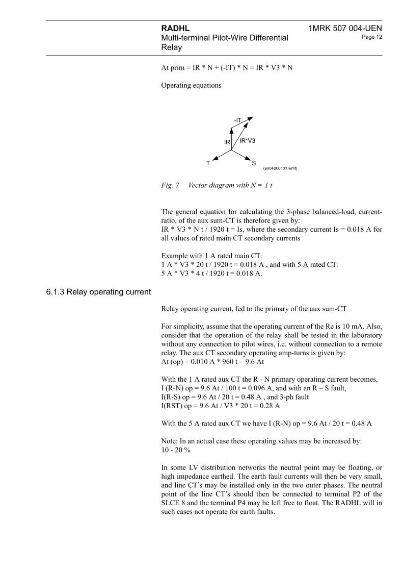
At prim = IR * N + (-IT) * N = IR * V3 * N
Operating equations
Fig. 7 Vector diagram with N = 1 t
The general equation for calculating the 3-phase balanced-load, current-ratio, of the aux sum-CT is therefore given by: IR * V3 * N t / 1920 t = Is, where the secondary current Is = 0.018 A forall values of rated main CT secondary currents
Example with 1 A rated main CT:1 A * V3 * 20 t / 1920 t = 0.018 A , and with 5 A rated CT:5 A * V3 * 4 t / 1920 t = 0.018 A.
Relay operating current, fed to the primary of the aux sum-CT
For simplicity, assume that the operating current of the Re is 10 mA. Also,consider that the operation of the relay shall be tested in the laboratorywithout any connection to pilot wires, i.e. without connection to a remoterelay. The aux CT secondary operating amp-turns is given by:At (op) = 0.010 A * 960 t = 9.6 At
With the 1 A rated aux CT the R - N primary operating current becomes, I (R-N) op = 9.6 At / 100 t = 0.096 A, and with an R – S fault, I(R-S) op = 9.6 At / 20 t = 0.48 A , and 3-ph fault I(RST) op = 9.6 At / V3 * 20 t = 0.28 A
With the 5 A rated aux CT we have I (R-N) op = 9.6 At / 20 t = 0.48 A
Note: In an actual case these operating values may be increased by: 10 - 20 %
In some LV distribution networks the neutral point may be floating, orhigh impedance earthed. The earth fault currents will then be very small,and line CT’s may be installed only in the two outer phases. The neutralpoint of the line CT’s should then be connected to terminal P2 of theSLCE 8 and the terminal P4 may be left free to float. The RADHL will insuch cases not operate for earth faults.
T S
IR IR*V3
-IT
(en04000101.wmf)

1MRK 507 004-UENPage 13
RADHLMulti-terminal Pilot-Wire Differential Relay
6.2 2-Terminals: normal loa
Fig. 8 With main CT’s in 2-phases only
The most typical application of the pilot-wire diff relay is the 2-terminalarrangement. For simplicity, and for ease of explaining the general princi-ples, we may assume that the pilot-wire current at normal load is 20 mA.The aux CT secondary output voltages at each end, then becomes 20 V,because the loop-resistance of each relay up to the electrical mid-pointEMP is 1000 ohms. Hence, the two relays at each end will work fullysymmetrical, and the total pilot-wire burden will be shared equallybetween the relays. Also, we may assume that the pilot-wire loop resis-tance seen at the output terminals: 9A - 10A, at each relay up to the mid-point is 500 ohms. The internal padding resistor of each relay may there-fore be set at zero.
Fig. 9 RADHL in a 2-terminal arrangement. EMP = Electrical Mid- Point For simplicity we have selected pilot-wire current Is = 20 mA
N P3
P4 S3
P1 S1
S2P2
3N
960 t
960 t
N
IT
IsIR
Re
(en04000102.wmf)
d current
GG
Station 2
Re2
Station 1I(load)
Re1
1 A1 A
20 V
-/1 A-/1 A
P1 P4S1 S3
S220 V20 mA
500 ohm
P1 P4S1 S3
S2
500 ohm
20 mA
20 mA
N2N1 Neutral
500 ohmBB
A10 9
A
B
A10 B
9A
EMP 20 mA
1 A aux CT, turns: 20-20-60 / 960-960 t
R S T N
(en04000103.wmf)

RADHLMulti-terminal Pilot-Wire Differential Relay
1MRK 507 004-UENPage 14
6.2.1 Normal load voltage diag
Volt
-20
20
0
10
-10 S
S
S
6.2.2 Fault current distribution
The voltage diagram indicate that the Re1 and Re2 measuring relays at thetwo ends, are in a position with zero volts across their operating coils.Also, in the case with a large through-fault current, the output voltages S1-S3 of the aux CT’s will be limited to about 60 V by zener diodes and theaux CT’s will therefore not saturate easily. If some main CT error shouldoccur, both relay ends will show similar errors and the measuring relaysRe will remain at zero potential, i.e. the RADHL will be stable in the caseof through faults.
Fig. 10 Typical voltage distribution diagram with 20 mA of circulating pilot-wire current
In the event of an internal fault, with infeed from one end only, bothrelays: Re:1 and :2, at the two ends, will operate at the same time, becauseboth relays will receive the same operating current, for simplicity assumedto be about 10 mA.
The operating amp-turns of the feeding aux CT, seen at the secondaryside, becomes: 5 mA * 960 t + 15 mA * 960 t = 19.2 At, and the primaryR-N operating current: I(R-N) = 19.2 At / 100 t = 0.0192 A with the 1 Arated aux CT (in actual case about 20 % higher).The current in the pilot-wire required to cause operation at the remote end will be only 5 mA,because its aux CT will work as an auto-transformer. The pilot-wire cur-rent of 5 mA will enter the S1 terminal, and 5 mA must also flow in theS2-S3 winding in order to obtain the necessary amp-turns balance. Hence,at terminal S2 an output of 10 mA will be obtained. This will cause theRe2 to operate.
ram
EMP
N1
Re2
N2
Re12
3
1
S2
S1
S3
20 mA 20 mA
20 mA
20 mA
10 V500 ohm
10 V500 ohm
500ohm
500ohm
20 mA
20 mA
20 V
(en04000104.wmf)

1MRK 507 004-UENPage 15
RADHLMulti-terminal Pilot-Wire Differential Relay
Station 1
Re
1 A
-/1 A
P1S1
5 mA
N1
B
A10
6.2.3 Fault voltage diagram
Fig. 11 Internal fault with infeed from one end only
Fig. 12 Stn: 2 has no primary current, and its aux CT secondary winding will work as an auto-transformers: S1 – S3 voltage = 2 * 12.5 = 25 V.
For simplicity it is assumed that the Re:1 and :2 will operate at 10 mA and10 V. The sending end voltage S1 – S3 is: 2 * 17.5 = 35 V and the receiv-ing end 2 * 12.5 = 25 V. The actual pickup values may be 20 % higher.
Station 2
Re2
I(fault)
125 V
-/1 A
P4S3
S2
35 V
P1 P4S1 S3
S2
500 ohm
5 mA
5 mA N2Neutral
500 ohmB9
A
B
A10 B
9A
EMP
15 mA500 ohm7.5 V
5 mA
10 mA10 mA2.5 V 5 mA 500 ohm
5 mA(en04000105.wmf)
5 mA 10 mA
5 mA5 mA
5 mA
S1 S3Re2 10 V
S22.5 V 500 ohm
(en04000106.wmf)
RADHLMulti-terminal Pilot-Wire Differential Relay
1MRK 507 004-UENPage 16
S3
S1
Re10
S2
10
20
30
10 mA
15 mA
157
N1
6.3 4-Terminals: normal loa
GG
IL
Station 1
5
IL=1 pu
S1
P1
S2
N1
Re118mA
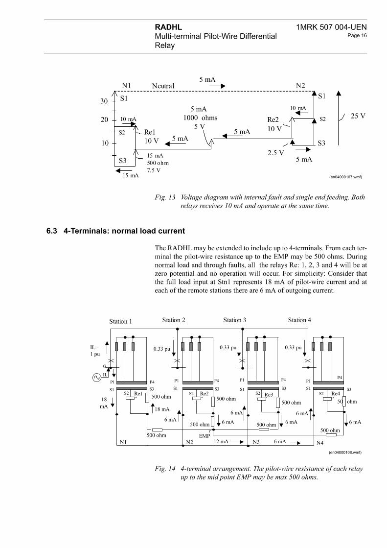
Fig. 13 Voltage diagram with internal fault and single end feeding. Both relays receives 10 mA and operate at the same time.
The RADHL may be extended to include up to 4-terminals. From each ter-minal the pilot-wire resistance up to the EMP may be 500 ohms. Duringnormal load and through faults, all the relays Re: 1, 2, 3 and 4 will be atzero potential and no operation will occur. For simplicity: Consider thatthe full load input at Stn1 represents 18 mA of pilot-wire current and ateach of the remote stations there are 6 mA of outgoing current.
Fig. 14 4-terminal arrangement. The pilot-wire resistance of each relay up to the mid point EMP may be max 500 ohms.
S31 V
5 mA1000 ohms
5 VS2
10 mA
5 mA00 ohm.5 V
5 mA
S1
5 mARe2 10 V
25 V
N2Neutral
2.5 V5 mA
5 mA
(en04000107.wmf)
d current
Station 2 Station 3 Station 4
00 ohm
6 mA
500 ohm
EMP
Re3
P4 P1
S3 S3 S3
P4
S3 S1S1
P1 P4 P1
500 ohm500 ohm
500 ohm 500 ohm
500 ohm
18 mA
6 mA 6 mA6 mA6 mA
12 mA
6 mA
6 mA
S2S2 S2
P4
500 ohm
S1
N2 N3
Re2 Re4
0.33 pu 0.33 pu0.33 pu
N4
(en04000108.wmf)

1MRK 507 004-UENPage 17
RADHLMulti-terminal Pilot-Wire Differential Relay
6.3.1 Normal load voltage diag
Re1
N1 N
S2
S3
S1
18 V
18 mA
9 V500
18 mA
6.3.2 Fault current distribution
GG
IF
Station 1
10 mA
R
N1
IF
S1
P1
S215 mA
At the sending end the output voltage S1- S3 is 18 V and at each of theremote ends the S3 – S1 voltage is 6 V. All relays Re: 1- 4 will be at zeropotential..The Neutral line and the EMP is at zero potential difference.This will always be the case independent of the actual loads at all stations,because all relays are connected symmetrically to the EMP.
Fig. 15 Voltage diagram with normal through going load. All relays Re.. at zero potential differences.
All relays Re:1 – 4 will operate at the same time, because they will receivethe same operating current (assumed to be 10 mA).The operating amp-turns of the feeding aux CT will be:15mA * 960 t + 25 mA * 960 t = 38.4At, and the primary R – N operating current: I(R-N) op = 38.4 At / 100 t =0.384 A with the 1 A rated aux CT (in actual case 30 % higher due tohigher voltage and magnetising currents)At the sending-end the pilot-wirecurrent is 15 mA and at each receiving-end 5 mA.
ram
Re2 Re4N3 N4N2S2
S3
S1S2S3
S1S2
S3
S1eutral
Line = EMP
Re3 6 V
9 V500 ohm
ohm
3 V3 V
6 mA 6 mA6 mA
(en04000109.wmf)
Station 2 Station 3 Station 4Fault
IF
500 ohm
5 mA10 mA 10 mA
500 ohm
EMP
Re2 Re3 Re4e1
N3
10 mA
N4N2
P4 P1
S3 S3 S1
P4
S3 S1S1
P1 P4 P1
500 ohm500 ohm
500 ohm500 ohm
500 ohm
25 mA
15 mA
5 mA
5 mA5 mA5 mA
5 mA
10 mA
5 mA
5 mA
S2S2 S2
P4
(en04000110.wmf)

RADHLMulti-terminal Pilot-Wire Differential Relay
1MRK 507 004-UENPage 18
6.3.3 Fault voltage diagram
S
S
S2
N1
10
20
30
40
10
2
Fig. 16 4-Terminals with internal fault fed from one end. All relays Re:1 – 4 will operate at the same time.
The sending end voltage S1 – S3 is 2 * (10 V + 12.5 V) = 45 V and at thereceiving ends 2 * 12.5 V = 25 V All relays Re: 1-2-3-4 operate at 10 Vand 10 mA.
Fig. 17 Voltage diagram with internal fault and single infeed.
Neutral 15 mA 10 mA 5 mA
5 mA
3
1 S1
S3
S1
S3
S1
S3
12.5 V
12.5 V
Re110 V
Re2 Re3 Re45 mA
500 ohms2.5 V
15 mA500 ohms
7.5 V
N2 N3 N4
S2S2 S2
Line = EMP
10 mA 10 mA10 mA
mA
5 mA
25 mA500 ohm12.5 V
15 mA
(en04000111.wmf)

1MRK 507 004-UENPage 19
RADHLMulti-terminal Pilot-Wire Differential Relay
7 INTERTRIPPING
RADH
HVCB
7.1 Opening pilot-wires
The figure shows a typical situation where intertripping is required. At theend of a: 0 – 12 km long feeder there is a step down power-transformer.The transformer’s diff + O/C & E/F relays will trip the LV circuit breakerdirectly, and may cause tripping of the remote HV circuit breaker bymeans of intertripping.
This is achieved by opening the RADHL’s pilot-wires. The operating cur-rent of the RADHL then becomes half of the normal operating values,because each end-relay need not (cannot) send an operating current via thepilots to the remote end. The operating sensitivity of this intertrippingscheme is, therefore in the range: 12.5 – 62.5 % of the CT rating, anddepends on the type of fault within the area of the power transformer.
Fig. 18 The feeder 0 – 12 km long may be protected by RADHL, and the power transformer by a differential relay + O/C & E / F. Inter-tripping can be obtained by opening the pilot-wires of the RADHL
Intertripping by opening pilot wires . When the pilot wires are opened, theaux CT secondary current can only flow in the S2-S3 winding = 960 t.Assume relay operating current is about 10 mA, then the primary aux CToperating current becomes:
I(R-N) = 960 t * 0.01 A / 100 t = 0.096 A i.e. about 10 % of In I(R-S) = 5* 10 % = 50 % of In, and I(R-S-T) = 50 % / V3 = ca 30 %
The RXMA1 aux relay opening the pilot-wires should normally be float-ing, i.e. not connected to any ground potential.
RADHLL O/C & E / FTransf d iff
0 – 12 kmLV
Pilot-wires
RXMA 1
Power Transformer
CB
(en04000112.wmf)

RADHLMulti-terminal Pilot-Wire Differential Relay
1MRK 507 004-UENPage 20
-
2
Fig. 19 The RXMA 1 may be initiated by all the power-transformer relays which require tripping of the remote CB.
GG
Station 2
Re2
Station 1 I(load)
Re1
5 A5 A
20 V
-/5 A/5 A
P1 P4S1 S3
S220 V0 mA 500 ohm
10 V
P1 P4S1 S3
S2
500 ohm
20 mA
20 mA
N2N1 Neutral
500 ohmBB
A10 9
A
B
A10 B
9A
EMP
RXMA1
Initiate
R S T N
(en04000113.wmf)

1MRK 507 004-UENPage 21
RADHLMulti-terminal Pilot-Wire Differential Relay
8 PILOT-WIRE SUPERVISIO
2 mA dc
Station 1
2 mA dc
DR1 mA oper
U1
U2 6 k
C B9A
B10A
S1 S2 S3
8.1 Faulty pilot-wire
The correct working of the pilot-wires can be supervised by injecting2 mA of circulating dc current. This will detect open pilot-wires, shortedpilots and also cross connected pilots. The principles of the scheme isbased on the balanced-bridge feature with a sensitive polarized directionalDR relay type RXCLK 2.
The voltages: U1 = U2 =12 V dc, produce 2 mA of circulating currentthrough a system comprising a lumped resistance of 6 k ohm (close to U2)and distributed external resistances of 4000 ohm + 4 * 500 ohm resistorsat Stn: 3 and :1. The voltage across the DR is zero during balanced condi-tions. Relay operation will occur when any of the pilots between Stns: 1-2or 2-3 are interrupted , shorted or cross-connected. At Stn:1 we have thesending end equipment and at Stn:2 and :3 the receiving end equipment.The Stn:2 has in fact no pilot-wire as it is directly connected to the EMP,and the capacitor C is therefore used only to block the dc current. In Stn:3the dc current will pass the diode D1 and the resistor of 4000 ohms. Thecapacitor C in all stations is large enough to enable the 50 – 60 Hz currentsto circulate without any problems.
Fig. 20 Pilot-Wire Supervision with 3-Terminal RADHL. Stn 2 is directly connected to the Electrical-Mid Point
For simplicity we may neglect the impedance of the DR.When the pilotsare wrongly opened, only the U2 voltage can send a current through theDR. The U1 voltage cannot send any current because the pilots areopened. The direction of current flow indicates: Opened pilots.
When the pilots are shorted, the U1 may send a current through the DRplus the 2* 500 ohms resistors. The U2 may send a current through the 6 kohm + the DR in the oposite direction. The U1 will produce the largestcurrent and this direction of flow will indicate: Shorted pilots.
When the pilots are crossed, the 2 mA of circulating current cannot flowbecause of the blocking diode D1. The indication will be the same as for:Opened pilots.
N
500ohm
500ohm
EMP
Station 3Station 2
C
2 mA dc
2 mA dc
C
S1 S2 S3 S1 S2 S3
500ohm
500ohm
2 mA dc
B10A
B9A
B9A
500ohm
500ohm
B10A
4000ohm
D1
(en04000114.wmf)

RADHLMulti-terminal Pilot-Wire Differential Relay
1MRK 507 004-UENPage 22
U1
6 kohm
C
Pilots: Opened
0 mA
2 mA
0
S1 S2 S3
U2
Station 1
(a)
DR
8.2 Pilot-wire dc loop circu
2
1D
1 k ohm
100 ohm
U1
S2
S1
S3
10 AB
B
I1
220 V
225
131: C
21
I1
313: RXTUB 2ac to dc converter
Fig. 21 The pilots may be wrongly: opened (a), shorted (b) and cross connected (c)
Fig. 22 For simplicity consider:During normal service I1 = I2 = 2 mA and the DR current is zero.
With shorted pilots I1 = 12 V / 1 k ohm = 12 mA and I2 = 12 V / 6 k ohm= 2 mA and I(DR) = 12 – 2 = 10 mA towards terminal 221
With open pilots I1 = 0 and I2 = 2 mA leaving terminal 221
6 k
4000ohm
D1
C
12 mA
12 mA
U2
0Pilots: Shorted
2 mA
I(DR) =12 – 2= 10 mA
Crossed
Blocked by D1= Opened12 mA
Station 3
S1 S2 S3S1 S2 S3
Station 1
C
(c)(b)
U1
500 ohm
500 ohm
(en04000115.wmf)
it
21
11R
4 k ohm
1 k ohm
6.2 k ohm
100 ohm
U2
10
A B9 A 9
A B S1
S3
S2Pilots:
I1 = I2
I2
I1= I2
ac
223224
I2
Shorted
I1
Opened
(en04000116.wmf)

1MRK 507 004-UENPage 23
RADHLMulti-terminal Pilot-Wire Differential Relay
8.3 Unbalance
U1=12 V
U2= 12 V
I1= I2 + IDR = 2.34
I2 = 2.05 mA
IDR = 0.29 mA
DR221
111
UDR =0.29 V
I1
I2
(a) With an unbalance of 1 kThe current in the directionaIDR = 0.29 mA and voltageUDR = 0.29 V
The actual value of the external dc-loop is about 6.2 k ohms and theadjustable sending end resistor should be set accordingly.
An unbalance can be created by inserting the test handle RTXH in the testswitch at the sending end, or at the remote end. The external loop-resis-tance will then be reduced from about: 4000 + 4 * 500 = 6000 ohm, toabout 4000 + 2* 500 = 5000 ohm.
Fig. 23 The directional relay DR (RXCLK) will obtain a spill quantity when the dc resistance of the two loops differ.
Fig. 24 Pilot-wire supervision equipment
5 k ohm 5.62 k ohm
U1=12 V
U2= 12 V
I1= I2 + IDR = 2.1166 mA
I2 = 2.0166 mA
IDR = 0.1 mA
DR221
111
UDR =0.1 V
11.9 V11.7 V
(b) With an unbalance of about 400 ohms:The current in the directional relay DR will be:IDR = 0.1 mA and voltage UDR = 0.1 V
I1
I2
mA
12..3 V
6 k ohm12.1 V
6 k ohm
ohm:l relay DR becomes:
(en04000117.wmf)
xx02000477
Receiving end unit(se99261.eps)

RADHLMulti-terminal Pilot-Wire Differential Relay
1MRK 507 004-UENPage 24
9 COMMISSIONING
9.1 Equipment required
9.2 Test procedure
It is recommended that commissioning be made with the protected feederin normal service with a load current of 10 % or more. The pilot-wire cur-rent will then be about 2 mA and the correct polarity of all the CT circuitsis easily checked.
1 - Test set type Sverker or similar
1 - RTXH-18 test handle with test leads
1 - Multi-purpose: voltmeter, ammeter and ohmmeter
2 - RTXM ammeter test plug
1 - RTXB trip circuit blocking pin per relay terminal.
The correct operation of the RADHL relay may be tested by inserting theRTXH test handle into the test switch.
• All main CT secondary terminals, at all feeder ends, must be shorted at all phases and disconnected from the RADHL. All relay trip cir-cuits must be disconnected. This may be achieved by inserting the RTXB blocking pin in test switch terminal 17. The operation of the auxiliary tripping relay can be observed by connecting a bleep-tester, or voltmeter, at the combiflex terminals of the RTXM.
• Inject a current to the RTXH terminals: 3 and 6 and check that the R - N operating current is about 50 % of the normal operating value, i.e. about 12 % of the CT rating (Ir).
• Inject a current to terminals 4 - 6 and 5 - 6, and check that operation for these phases is obtained with currents of about: (5 t /4 t)* 12 = 15 % and (5 t / 3 t) * 12 = 20 % of Ir
These tests confirm that the aux sum-CT and the RADHL relay are work-ing correctly.
All relays at all ends must be tested similarly.
Check that the pilot-wires and the padding resistors are correctly adjustedas described in Section 5.
Remove the test handle (at all ends) and, at one end, inject a current at the R-N primary terminals of the aux sum CT.
Check that all relays operate as follows:
2 -terminal relay, both relays operate at about 24 % of rated current.
3 - terminal relay, all 3-relays operate at about 32 % of rated current
4 -terminal relay, all 4-relays operate at about 55 % of rated current.
These tests confirm that the connections to the remote ends are correct.

1MRK 507 004-UENPage 25
RADHLMulti-terminal Pilot-Wire Differential Relay
9.3 CT polarity check
This is most easily carried out when the primary load current is 10 % ormore.All main CT secondary circuits must now be connected to the aux sum CTprimary terminals. However, all the main CT secondary circuits mustremain short-circuited. In one station the following should be done:
1) Remove carefully the R - N shorting lead and observe that no sparkingoccurs.
2) Remove the shorting leads of the other phases.
3) Insert the ammeter test plug: RTHM + ammeter, in the pilot-wire testswitch terminal: 9 or 10.
• Record the pilot-wire current: I(pw) = • 4) Record the primary load current I(pr) = • Connect an ac-voltmeter to the RXDHL's measuring relay terminals:
421 - 422, and record the unbalance relay voltage: (Re) = Note: This voltage may be in the range: 1 - 6 V ac, depending on the pri-mary load. Such a small unbalance is acceptable to remain intact and thecommissioning tests may therefore be continued in the remote stations.
At each of the remote stations the following should be done:
• Connect an ac-voltmeter to the RXDHL's measuring relay terminals: 421 - 422, and record the unbalance relay voltage: U(Re) = V ac
This voltage should be less than that recorded in the 1'st station, providedthe primary load current is the same.
1) Remove carefully the R - N shorting lead and observe that no sparking occurs.
2) Remove the shorting leads of the other phases.
3) Record the unbalance relay voltage: U(Re) = V ac
Note: When all the remote relays are in service, the U(Re) must be lessthan 2 V ac, when the primary load is 50 % of Ir..
At the 1'st station.
• Check that the U(Re) is less than 2 V dc when the primary load is 50 % of Ir
The multi-terminal RADHL relay may now be put in full service and theRTXB blocking of the trip circuits may be removed.

RADHLMulti-terminal Pilot-Wire Differential Relay
1MRK 507 004-UENPage 26
9.4 Pilot-wire supervision (
Ordering number: 1MRK 001 357-AA. Circuit diagram 1MRK 001 358-AA
All RADHL trip circuits must be blocked. The blocking pin RTXB may beinserted in test terminal 17. All main CT secondary circuits must beshorted.
• Check that the adjustable resistor (5 + 3.9 kohm) at the sending end in the capacitor unit 125:2 - 3 are adjusted to about 6.2 kohm.
• Check that the external, pilot-wire dc-loop circuit resistance is about 6.2 kohms. See Fig. 22. Insert the ammeter test plug RTXM in the test switch terminal: 10. An ohmmeter may be connected to the RTXM's left hand side (red) banana plug and the capacitor terminal 125:2. The internal loading resistor of the RXTUB 2 will then not affect the measurement. The RTXM's right hand side (blue) banana plug must be kept insulated.
• Measured external dc-loop resistance:• Switch on the ac supply to the RXTUB 2, and check with the RTXM
+ ammeter, in test terminal 10, that the dc current is about 2 mA dc• A dc voltmeter may now be connected to the RXCLK terminals
101:111 - 221, with (+) to:111. The resistor 125:2 - 3 may be adjusted to about zero, or + 0.1 V dc. The extra + unbalance voltage will increase the margin to get good operation on: Open pilot-wire.
• Insert the: RTXM + dc voltmeter, in test switch terminal 10 and check that the dc voltage (U1 in Fig. 22) is about 12 V dc.
• Check that the: Open pilot-wire alarm is obtained after 5 sec set on 113: RXKA 1.
• Put a short circuit on the pilot-wire terminals and check that the: Shorted pilot-wire alarm is obtained after 5 sec set on 119: RXKA 1.
The PWS alarm may now be put in normal service.
PWS)

1MRK 507 004-UENPage 27
RADHLMulti-terminal Pilot-Wire Differential Relay
Rate
Ac b
Cont
Freq
Sensep
Oper
Maxi
Maxi
Dielecpr
Impu
DistuPF1
Flag
Trip
10 TECHNICAL DATA
d current, Ir 1 or 5 A
urden 3 VA, total for three-phase
inuous overload capacity 2 . Iruency 50-60 Hz
itivity:arth faultshase faults
2-terminals25-42% of Ir 64-126% of Ir
3-terminals40-66%100-200%
4-terminals60-100%150-300%
ating time 20 ms at 1,5 Ipick-up
mum pilot-wire resistance 1000 ohms (2000 ohms with isolating transformer ratio 1:1,7)
mum pilot-wire capacitance 2,0 µF (0,7 µF with isolating transformer ratio 1:1.7)
ctric tests: urrent circuits ilot-wireemaining circuits
50 Hz, 2,5 kV, 1 min50 Hz, 5,0 kV, 1 min 50 Hz, 2,0 kV, 1 min
lse voltage test 1,2/50 µs, 5 kV, 0,5 J
rbance Tests: ower frequency test ast frequency test MHz burst test
50 Hz, 0,5 kV, 2 min 4-8 kV, 2 min2,5 kV, 2 s
relay auxiliary voltage 24-55 V or 110-250 V
outputs 2 make contacts capable of closing 30A dc for 200ms

RADHLMulti-terminal Pilot-Wire Differential Relay
1MRK 507 004-UENPage 28
Specify:Quantity
Ordering nu
Rated curren
Auxiliary vol
Ordering nuPilot-wire re
Basic versionSLCE 8 and
Basic version
Basic version
Basic versionfurnished loo
Basic versionfurnished loo
Basic versionfurnished loo
Pilot-wire suSending endReceiving en
SLCE 8 - 15transformer Ratio 1:1 forRatio 1:1,7 fo
As spare paRXDHL 4 loo
SLCE 8 sum
1) Please no
11 ORDERING
mber according to table
t 1 A 5 A
tage UL 24 V 48 V 110 V 125 V 220 V 250 V
mber selection table for two terminals applicationlay Dimen-
sionsWeight Terminal diagram Ordering No.
(includes summation CT test switch RTXP 18)
4U 36C 5,2 kg 7434 209-EAA RK 612 001-EA
+ output relay RXME 1 4U 42C 5,7 kg 7434 209-GAA RK 612 001-GA
+ output relay RXMS 1 4U 42C 5,7 kg 7434 209-HAA RK 612 001-HA
with summation CTse
4U 18C 3,0 kg 7434 209-ACA RK 612 001-AC
with summation CTse + output relay RXME 1
4U 24C 5,3 kg 7434 209-BCA RK 612 001-BC
with summation CTse + output relay RXMS 1
4U 24C 5,4 kg 7434 209-DAA RK 612 001-DA
pervision equipment: unit d unit
4U 48C4U 18C
6,5 kg2,0 kg
1MRK 001 358-AAA7434 211-CA
1MRK 001 357-AA7434 210-CA
kV Pilot-wire isolation
1000 Ohm pilot-wirer 2000 Ohm pilot-wire
3,6 kg
4785 040-AUP4785 040-BAL
rtse relay1) RX4 1,5 kg Fig. 5 RK 612 010-EA
mation CT 5 A1 A
3,6 kg3,6 kg
Fig. 5 Fig. 5
4785 040-SY4785 040-SV
te that terminal base RX4 is not included.

1MRK 507 004-UENPage 29
RADHLMulti-terminal Pilot-Wire Differential Relay
Specify:Quantity
Ordering num
Rated curren
AC inputs fRated phase
Rated phase
Rated phase
Rated phase
Rated phase
Ordering nuPilot-wire re
Basic versiodetectors typ
Basic versiofault detecto
Basic versiofault detecto
Options foAutomatic reincluded
Binary I/O m
11.1 Versions with addition
11.1.1 Mounting and testing de
• RADHL and the pilot-wire supervision equipment are delivered mounted on apparatus bars.
• Depending on the type of final mounting required, i.e. 19” rack-mounting, or various forms of panel mounting, additional equipment is required.
• On request the 15 kV pilot-wire transformer, can be mounted on an apparatus plate or in a suitable casing.
ber according to table
t 1 A 5 A
or RXHL 401 and RXHL 411 current Ir = 1 A, rated neutral current INr = 0.1 A 1MRK 000 322-FA
current Ir = 1 A, rated neutral current INr = 1 A 1MRK 000 322-FB
current Ir = 5 A, rated neutral current INr = 0.1 A 1MRK 000 322-FC
current Ir = 5 A, rated neutral current INr = 1 A 1MRK 000 322-FD
current Ir = 5 A, rated neutral current INr = 5 A 1MRK 000 322-FE
mber selection table for two terminals applicationlay Dimen-
sionsWeight Terminal diagram Ordering No.
n + 3 single phase fault e RXIDK 2H
4U 60C 7,5 kg 7434 209-FBA RK 612 001-FB
n + 3 phase and earth rs type RXHL 401
4U 60C 6,5 kg 1MRK002078-AAA 1MRK002077-AA
n + 3 phase and earth rs type RXHL 411
4U 60C 6,5 kg 1MRK002078-AAA 1MRK002077-AB
r RXHL 411closing function with intentional overreach trip function 1MRK 000 200-BA
odule (inputs 4/outputs 4) 1MRK 000 322-ET
al fault detectors
tails

RADHLMulti-terminal Pilot-Wire Differential Relay
1MRK 507 004-UENPage 30

1MRK 507 004-UENPage 31
RADHLMulti-terminal Pilot-Wire Differential Relay

RADHLMulti-terminal Pilot-Wire Differential Relay
1MRK 507 004-UENPage 32

1MRK 507 004-UENPage 33
RADHLMulti-terminal Pilot-Wire Differential Relay

RADHLMulti-terminal Pilot-Wire Differential Relay
1MRK 507 004-UENPage 34

1MRK 507 004-UENPage 35
RADHLMulti-terminal Pilot-Wire Differential Relay

RADHLMulti-terminal Pilot-Wire Differential Relay
1MRK 507 004-UENPage 36

1MRK 507 004-UENPage 37
RADHLMulti-terminal Pilot-Wire Differential Relay
en03000067.vsd

RADHLMulti-terminal Pilot-Wire Differential Relay
1MRK 507 004-UENPage 38

1MRK 507 004-UENPage 39
RADHLMulti-terminal Pilot-Wire Differential Relay

RADHLMulti-terminal Pilot-Wire Differential Relay
1MRK 507 004-UENPage 40
12 REFERENCE
13 MANUFACTURER
RADHL Buyer’s guide 1MRK 507 004-BENCOMBIFLEX mounting hardware details 1MRK 513 003-BENCOMBITEST test equipment details 1MRK 512 001-BENRXIDK 2H current moitoring relay 1MRK 509 002-BENRXHL 401 current monitoring relay 1MRK 509 062-BENRXHL 411 current monitoring relay 1MRK 509 049-BENRXME 1 intertrip auxiliary relay 1MRK 508 015-BENRXMS 1 intertrip auxiliary relay 1MRK 508 015-BEN
ABB Automation Technologies ABSubstation AutomationSE-721 59 VästeråsSwedenTelephone: +46 (0) 21 34 20 00Facsimile: +46 (0) 21 14 69 18www.abb.com/substationautomation
![JEONO]catalog_E.pdf · Terminal Blocks and Wire Connectors Terminal Blocks—JOTN Terminal Block Accessory—Stopper, Separator Two Floor JOTN EIO Ell .E12 -E12 £13](https://img.pdfslide.us/doc/110x75/5b3743a67f8b9ab9068c0f70/jeonocatalogepdf-terminal-blocks-and-wire-connectors-terminal-blocksjotn.jpg)