Embed Size (px)
Citation preview

Dow
nloa
ded
from
asc
elib
rary
.org
by
Uni
vers
ity o
f B
righ
ton
on 0
3/10
/13.
Cop
yrig
ht A
SCE
. For
per
sona
l use
onl
y; a
ll ri
ghts
res
erve
d.
Two Approaches of Finite-Element Modeling of BallastedRailway Track
Chen-Ming Kuo1 and Cheng-Hao Huang2
Abstract: Use of a ballast is still popular in railway engineering due to its resilience, relatively low noise, and convenience inconstruction and maintenance. The ballast layer was modeled with two modeling approaches in this study–continuous elastic solid andspring-connected elements. Two-dimensional finite element models were built. The parameters of ballast layers were correlated betweentwo models to assure comparability. Three levels of vehicle moving speed were analyzed with the models. Significant differences of raildeflection and ballast were found in all speed levels. Vibration spectra were also compared to reveal the characteristics of different finiteelement models. It was found that the model with spring-connected discrete elements had higher characteristic frequency than the simpleballast model. Increasing speed may significantly increase rail deflections and ballast vibration levels and result in particles movements inthe ballast layer. A thorough understanding of model characteristics and engineering problems is crucial to choose the most appropriatemodel.
DOI: 10.1061/�ASCE�1090-0241�2009�135:3�455�
CE Database subject headings: Finite element method; Ballast; Vibration; Parameters.
Introduction
A ballasted track is popular because of its vibration absorbingability, low noise, and ease of construction and maintenance.However, the settlement–load behavior of a ballast track is toocomplicated to predict by means of theoretical or empirical equa-tions �Anderson and Key 2000�. In-depth studies are needed toensure the integrity of ballast track structures.
In common practice, a ballast layer is usually considered as acontinuum complying with the theory of continuum mechanics,although the ballast is composed of coarse grained granular mediaresembling an assemblage of discrete particles �Prevost and Pope-scu 1996�. Discrete supports on elastic solid have been adoptedby Vostroukhov and Metrikine �2003� to model sleeper supportson ballast layers for exploring the significance of vehicle speed onground waves. Analyses, of ballast support, either with discretesprings or a finite-thickness layer of elastic continuum, have beenreported �Liang et al. 2001; Sheng et al. 1999; Sun and Dha-nasekar 2002�. Zhai et al. �2004� proposed a five-parameter bal-last model based on the hypothesis of load transmission withinthe ballast as a cone distribution under a sleeper. It was concludedthat consideration of the ballast shearing effect between ballastparticles is necessary to model the continuity and the couplingeffects of the interlocking ballast granules.
The track has been modeled with a finite element method as a
1Associate Professor, Dept. of Civil Engineering, National ChengKung Univ., Taiwan, 1 University Rd., Tainan 70101, Taiwan �corre-sponding author�. E-mail: [email protected]
2Ph.D. Candidate, Dept. of Civil Engineering, National Cheng KungUniv., Taiwan, 1 University Rd., Tainan 70101, Taiwan. E-mail:[email protected]
Note. Discussion open until August 1, 2009. Separate discussionsmust be submitted for individual papers. The manuscript for this technicalnote was submitted for review and possible publication on May 22, 2007;approved on May 21, 2008. This technical note is part of the Journal ofGeotechnical and Geoenvironmental Engineering, Vol. 135, No. 3,
March 1, 2009. ©ASCE, ISSN 1090-0241/2009/3-455–458/$25.00.JOURNAL OF GEOTECHNICAL AND G
J. Geotech. Geoenviron. Eng
two-layer, three-layer, or even four-layer system �Dong et al.1994; Kalker 1996; Dukkipati and Dong 1999�. Hou et al. �2003�developed a finite element model to simulate an asymmetricalvehicle/track dynamic system consisting of a vehicle model toexplore the interactions between track and vehicles. Wang et al.�2005� built a three-dimensional finite-element model by simulat-ing ballast as a linear elastic layer to investigate the benefits ofusing rubber-modified asphalt concrete in high-speed railwayfoundations. Ju et al. �2007� validated field measured train-induced vibration along a high speed railway with three-dimensional finite element analysis by examining vibrationvelocities of ground soil particles.
One of the common criticisms of the analysis for coarsegrained granular media is the appropriateness of interpreting bal-last behaviors with elastic continuum models. Rigorous modelingtechniques have evolved into discontinuous deformation analysis,which is beyond the scope of this study �Lim and McDowell2005; Lobo-Guerrero and Vallejo 2006�. A simplified ballastmodel by connecting discrete finite elements with contact springswas proposed to be analogous to realistic compacted particles. Itis desirable to enhance the appropriate selection of analysismodel, as well as to shed light on characteristics of a ballastedtrack.
One 40 m rail was meshed into three-node quadratic beamelements 0.67 m in length under symmetrical assumption withrespect to the railway centerline. Parallel springs are adopted tosimulate rail pads. The simple model treated the ballast layeras a continuously elastic solid, as shown in Fig. 1. The two-dimensional model in this research represents a vertical slice cut-ting along the traffic centerline. The width of the ballast layer isconsidered significantly larger than the thickness. Negligiblestrains in the direction perpendicular to the cutting face justify theuse of plane-strain elements for the ballast layer. Thus, the ballastlayer was composed of eight-node plane-strain elements. Sleeperswere modeled with mass elements to account for dynamic effectsand neglect deformations.
The discrete model was built to emphasize the discontinuous
EOENVIRONMENTAL ENGINEERING © ASCE / MARCH 2009 / 455
. 2009.135:455-458.
Dow
nloa
ded
from
asc
elib
rary
.org
by
Uni
vers
ity o
f B
righ
ton
on 0
3/10
/13.
Cop
yrig
ht A
SCE
. For
per
sona
l use
onl
y; a
ll ri
ghts
res
erve
d.
feature of ballast particles. Numerous 48 mm�48 mm squarefour-node plain-stress elements were connected with springs tosimulate interactions among aggregates, as shown in Fig. 2. Theparticles were modeled with plane-stress elements because theproposed two-dimensional model represents a vertical slice cut-ting along the traffic centerline with the size of typical gravel.Each element represents single gravel interacting with adjacentsections if gravel with the connecting springs. Thus, the stress ofthe element in the direction perpendicular to the cutting face canbe negligible. The sleepers were also modeled with eight-nodeplain-strain elements as the simple model. The parameters in bothmodels were correlated as follows to ensure comparability be-tween two models.
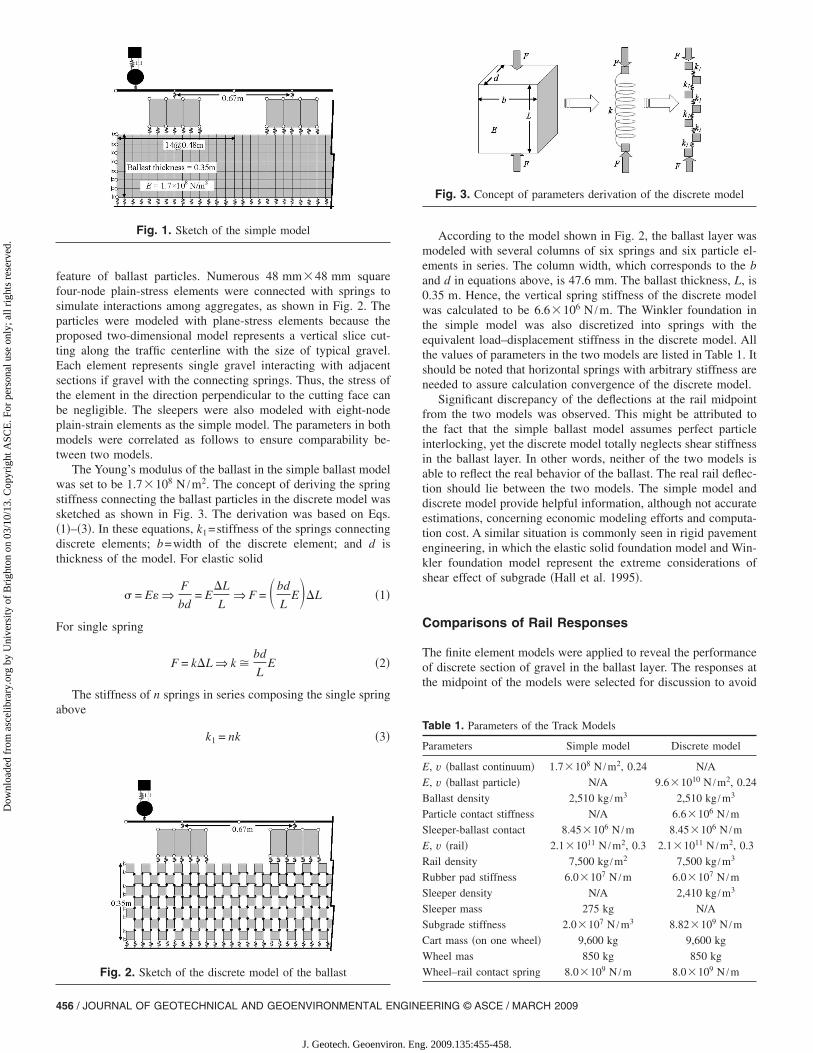
The Young’s modulus of the ballast in the simple ballast modelwas set to be 1.7�108 N /m2. The concept of deriving the springstiffness connecting the ballast particles in the discrete model wassketched as shown in Fig. 3. The derivation was based on Eqs.�1�–�3�. In these equations, k1=stiffness of the springs connectingdiscrete elements; b=width of the discrete element; and d isthickness of the model. For elastic solid
� = E� ⇒F
bd= E
�L
L⇒ F = �bd
LE��L �1�
For single spring
F = k�L ⇒ k �bd
LE �2�
The stiffness of n springs in series composing the single springabove
k1 = nk �3�
Fig. 1. Sketch of the simple model
Fig. 2. Sketch of the discrete model of the ballast
456 / JOURNAL OF GEOTECHNICAL AND GEOENVIRONMENTAL ENGINE
J. Geotech. Geoenviron. Eng
According to the model shown in Fig. 2, the ballast layer wasmodeled with several columns of six springs and six particle el-ements in series. The column width, which corresponds to the band d in equations above, is 47.6 mm. The ballast thickness, L, is0.35 m. Hence, the vertical spring stiffness of the discrete modelwas calculated to be 6.6�106 N /m. The Winkler foundation inthe simple model was also discretized into springs with theequivalent load–displacement stiffness in the discrete model. Allthe values of parameters in the two models are listed in Table 1. Itshould be noted that horizontal springs with arbitrary stiffness areneeded to assure calculation convergence of the discrete model.
Significant discrepancy of the deflections at the rail midpointfrom the two models was observed. This might be attributed tothe fact that the simple ballast model assumes perfect particleinterlocking, yet the discrete model totally neglects shear stiffnessin the ballast layer. In other words, neither of the two models isable to reflect the real behavior of the ballast. The real rail deflec-tion should lie between the two models. The simple model anddiscrete model provide helpful information, although not accurateestimations, concerning economic modeling efforts and computa-tion cost. A similar situation is commonly seen in rigid pavementengineering, in which the elastic solid foundation model and Win-kler foundation model represent the extreme considerations ofshear effect of subgrade �Hall et al. 1995�.
Comparisons of Rail Responses
The finite element models were applied to reveal the performanceof discrete section of gravel in the ballast layer. The responses atthe midpoint of the models were selected for discussion to avoid
Table 1. Parameters of the Track Models
Parameters Simple model Discrete model
E, v �ballast continuum� 1.7�108 N /m2, 0.24 N/A
E, v �ballast particle� N/A 9.6�1010 N /m2, 0.24
Ballast density 2,510 kg /m3 2,510 kg /m3
Particle contact stiffness N/A 6.6�106 N /m
Sleeper-ballast contact 8.45�106 N /m 8.45�106 N /m
E, v �rail� 2.1�1011 N /m2, 0.3 2.1�1011 N /m2, 0.3
Rail density 7,500 kg /m2 7,500 kg /m3
Rubber pad stiffness 6.0�107 N /m 6.0�107 N /m
Sleeper density N/A 2,410 kg /m3
Sleeper mass 275 kg N/A
Subgrade stiffness 2.0�107 N /m3 8.82�109 N /m
Cart mass �on one wheel� 9,600 kg 9,600 kg
Wheel mas 850 kg 850 kg
Wheel–rail contact spring 8.0�109 N /m 8.0�109 N /m
Fig. 3. Concept of parameters derivation of the discrete model
ERING © ASCE / MARCH 2009
. 2009.135:455-458.

Dow
nloa
ded
from
asc
elib
rary
.org
by
Uni
vers
ity o
f B
righ
ton
on 0
3/10
/13.
Cop
yrig
ht A
SCE
. For
per
sona
l use
onl
y; a
ll ri
ghts
res
erve
d.
interference caused by the reflections due to boundaries. Themaximum rail midpoint deflection of the discrete model is higherthan the simple model. This agrees with the responses of differentpavement foundation models �Losberg 1960�. The pavementmodel with Winkler foundation was found to give higher deflec-tion than the elastic solid foundation.
Frequency spectra of vibration velocity at the rail midpoint attwo moving speeds are shown in Fig. 4. The two models gavealmost identical results below 16 Hz. The discrete model hashigher vibration levels in the frequency range above 25 Hz. Thegap between the models narrows as speed increases. For metrosystems with typical speed less than 100 km/hr �kph�, the simpleballast model is likely to underestimate rail vibration levels of thefrequencies between 32 and 150 Hz according to Fig. 4. Thesimple ballast model has a possible resonant frequency at about20 Hz, which is lower than the 40 Hz in the discrete model. Dif-ferent resonant frequency could lead to different resolutions ofvibration or noise problems.
Comparisons of Ballast Layer Responses
Spectra in terms of vibration velocity at the top of the ballastlayer were compared as shown in Fig. 5. Generally, the simplemodel predicted higher vibration level in the range below 40 Hz,yet gave lower vibration level in high frequencies. Fig. 5 alsoillustrates that vehicle speed increases ballast vibration level. Ex-periments have shown that the resonant frequencies of variousgranular materials are around 10 Hz �Alekseev et al. 2000�.Hence, normal traffic may cause resonance of ballast gravels,which may further increase particle motion and ballast settle-ments. High speed lines are more vulnerable to ballast degrada-tion than normal lines. Due to its higher vibration level in lowfrequency range, the simple model could result in conservativepredictions on ballast deterioration rate.
Fig. 4. Comparison of rail vibration spectra at different speeds
Fig. 5. Comparisons of ballast vibration spectra at different speeds
JOURNAL OF GEOTECHNICAL AND G
J. Geotech. Geoenviron. Eng
Fig. 6 shows that the ballast movement in the discrete modelseems relatively stable for different moving speeds. On the otherhand, the simple model illustrated that high speed trains maycause high ballast deflections. The differences of peak deflectionsbetween the two models in high speed cases are more significantthan that of the 72 kph case.
Conclusions
A finite-element ballast model was proposed to simulate com-pacted particles with elements connected by springs. With theproposed parameter correlations, deflections and vibrations at themidpoint were compared between the discrete model and thesimple model.
The simple model, treating the ballast as an elastic solid, tendsto predict larger deflections in the ballast layer, but smaller de-flections of rail than the discrete model does. The discrepanciesbetween the two models increase with wheel moving speed.
As for vibration characteristics, the peak frequencies of railvibration were found in all speed levels at about 200 Hz in bothmodels. The high speed case has high ballast vibration. Bothmodels showed that high frequency vibrations become significantfor high speed lines.
For the ballast part, the simple model predicted lower resonantfrequency than the discrete model. Precautions are needed in se-lecting models to evaluate the susceptibility of low frequencyvibration problems or rumble noise.
Ballast vibrations were found sensitive to vehicle movingspeed. High speed lines might cause severe ballast vibration anddemand high quality ballast or intense maintenance.
The simple ballast model may result in conservative predic-tions on ballast deterioration rate. It also has lower resonant fre-quency than that of the discrete model. Reference can be made tothe results of both models in determining the real vibration char-acteristics of the ballast as the real behavior of the ballast ought tolie in between the two.
References
Alekseev, V. N., Gromov, A. N., Gromov, Y. I., Ovcharenko, A. T., andRybak, S. A. �2000�. “Motion of bodies under vibration in granularmedia.” Acoust. Phys., 46�3�, 243–248.
Anderson, W. F., and Key, A. J. �2000�. “Model testing of two-layerrailway track ballast.” J. Geotech. Geoenviron. Eng., 126�4�, 317–323.
Fig. 6. Comparison deflections of the ballast at top of the modelcenter
Dong, R. G., Sankar, S., and Dukkipati, R. V. �1994�. “A finite element
EOENVIRONMENTAL ENGINEERING © ASCE / MARCH 2009 / 457
. 2009.135:455-458.

Dow
nloa
ded
from
asc
elib
rary
.org
by
Uni
vers
ity o
f B
righ
ton
on 0
3/10
/13.
Cop
yrig
ht A
SCE
. For
per
sona
l use
onl
y; a
ll ri
ghts
res
erve
d.
model of railway track and its application to the wheel flat problem.”Proc. Inst. Mech. Eng., F J. Rail Rapid Transit, 208�1�, 61–72.
Dukkipati, R. V., and Dong, R. �1999�. “The dynamic effects of conven-tional freight car running over a dipped-joint.” Veh. Syst. Dyn., 31�2�,95–111.
Hall, K. T., Darter, M. I., and Kuo, C. M. �1995�. “Improved methods forselection of k value for concrete pavement design.” TransportationResearch Record. 1505, Transportation Research Board, Washington,D.C., 128–136.
Hou, K., Kalousek, J., and Dong, R. �2003�. “A dynamic model for anasymmetrical vehicle/track system.” J. Sound Vib., 267�3�, 591–604.
Ju, S.-H., Lin, H. T., and Chen, T. K. �2007�. “Studying characteristics oftrain-induced ground vibrations adjacent to an elevated railway byfield experiments.” J. Geotech. Geoenviron. Eng., 133�10�, 1302–1307.
Kalker, J. J. �1996�. “Discretely supported rails subjected to transientloads.” Veh. Syst. Dyn., 25�1�, 71–88.
Liang, B., Zhu, D., and Cai, Y. �2001�. “Dynamic analysis of the vehicle-subgrade model of a vertical coupled system.” J. Sound Vib., 245�1�,79–92.
Lim, W. L., and McDowell, G. R. �2005�. “Discrete element modelling ofrailway ballast.” Granular Matter, 7�1�, 19–29.
Lobo-Guerrero, S., and Vallejo, L. E. �2006�. “Discrete element method
458 / JOURNAL OF GEOTECHNICAL AND GEOENVIRONMENTAL ENGINE
J. Geotech. Geoenviron. Eng
analysis of railtrack ballast degradation during cyclic loading.”Granular Matter, 8�3–4�, 195–204.
Losberg, A. �1960�. Structurally reinforced concrete pavements, Chalm-ers Tekniska Hogskola, Goteborgg, Germany.
Prevost, J. H., and Popescu, R. �1996�. “Constitutive relations for soilmaterials.” Electron. J. Geotech. Eng., 1, �www.ejge.com/1996/Ppr9609/Ppr9609.htm�.
Sheng, X., Jones, C. J. C., and Petyt, M. �1999�. “Ground vibration gen-erated by a load moving along a railway track.” J. Sound Vib., 228�1�,129–156.
Sun, Y. Q., and Dhanasekar, M. �2002�. “A dynamic model for the ver-tical interaction of the rail track and wagon system.” Int. J. SolidsStruct., 39�5�, 1337–1359.
Vostroukhov, A. V., and Metrikine, A. V. �2003�. “Periodically supportedbeam on a visco-elastic layer as a model for dynamic analysis of ahigh-speed railway track.” Int. J. Solids Struct., 40�21�, 5723–5752.
Wang, J. C., Zeng, X., and Mullen, R. L. �2005�. “Three-dimensionalfinite element simulations of ground vibration generated by high-speed trains and engineering countermeasures.” J. Vib. Control,11�12�, 17.
Zhai, W. M., Wang, K. Y., and Lin, J. H. �2004�. “Modelling and experi-ment of railway ballast vibrations.” J. Sound Vib., 270�4–5�, 673–683.
ERING © ASCE / MARCH 2009
. 2009.135:455-458.