Embed Size (px)
Citation preview

Accepted Manuscript
Behaviour of Under-Track Crossings on Ballasted Railways
William Powrie, Louis Le Pen, David Milne, Geoff Watson, John Harkness
PII: S2214-3912(19)30102-3DOI: https://doi.org/10.1016/j.trgeo.2019.100258Article Number: 100258Reference: TRGEO 100258
To appear in: Transportation Geotechnics
Received Date: 19 March 2019Revised Date: 1 July 2019Accepted Date: 2 July 2019
Please cite this article as: W. Powrie, L. Le Pen, D. Milne, G. Watson, J. Harkness, Behaviour of Under-TrackCrossings on Ballasted Railways, Transportation Geotechnics (2019), doi: https://doi.org/10.1016/j.trgeo.2019.100258
This is a PDF file of an unedited manuscript that has been accepted for publication. As a service to our customerswe are providing this early version of the manuscript. The manuscript will undergo copyediting, typesetting, andreview of the resulting proof before it is published in its final form. Please note that during the production processerrors may be discovered which could affect the content, and all legal disclaimers that apply to the journal pertain.

1
Behaviour of Under-Track Crossings on Ballasted Railways
William Powrie, Louis Le Pen, David Milne, Geoff Watson, John Harkness
University of Southampton, Infrastructure Research Group, University of Southampton; UK
E-mail addresses: [email protected], [email protected], [email protected], [email protected]
ABSTRACT: Signal and telecommunications (S&T) cables and other services often cross underneath
a railway line in a duct or conduit, buried in the ground below the ballast. These under track
crossings (UTX) are likely to increase or decrease the track support stiffness compared with the
surrounding ground, depending on the material and construction detail of the crossing. This
change in support stiffness will give rise to variations in the dynamic loads exerted by moving
trains, with the potential to cause track damage. This paper presents measurements of track
deflections at two sites associated with different forms of UTX. The data are then used in finite
element based vehicle-track interaction analyses to assess the effects of UTX type and
construction on track geometry and performance. The results show that poor performance
observed at these sites cannot be explained by the difference in support stiffness alone, but
follows the development of gaps or voids between the sleeper base and the ballast.
Keywords: UTX; under track crossings; transitions, railway, ballast
1. Introduction
As train speeds increase, whether on new lines dedicated to high speed trains or on upgraded
existing lines, the influence of relatively minor inhomogeneities in trackbed support conditions
becomes more significant. Variations in support conditions occur most notably at transitions onto
and off structures such as underbridges in otherwise conventional ballasted railway track. Many
studies in the literature have focused on the impact of such features on track quality and
geometry (e.g. Paixao et al 2013, Mishra et al 2014). Typically, transitions onto and off the harder
supporting structure are associated with groups of voided or hanging sleepers at the approach and
exit. The effects of such hanging sleepers on the behaviour of railway vehicles and track has been
extensively investigated, usually by numerical modelling (e.g. Zhang et al 2008, Zhu et al 2011).
A less well-known but equally significant problem occurs with smaller interruptions in the
continuity of the trackbed support resulting from under track cable ducts or waterway culverts. An
increasing awareness of the tendency for the development of track geometry faults at such
locations has led to attempts to mitigate the effect by increasing the burial depth of under track
crossings. However, this approach has been only partly successful. This paper examines ways in
which under-track cable crossings (UTX) can lead to the development of trackbed faults, and
discusses some important effects of installation and maintenance methods on UTX performance.
2. Background
Many railways were built to accommodate trains travelling at slower maximum speeds than today.
As trains have become faster, populations grown and rail networks become more congested, the

2
impact of UTX at locations where services and streams must pass from one side of the track to the
other has increased.
Fig.1a shows a signal cable passing beneath the rail in an orange duct. Observations and
measurements at this site indicated that the apparently innocuous orange ducting coincided with
locally voided sleepers. Amongst a number of contributory factors the cable duct, which
prevented the use of mechanized tampers, was probably the most significant (Le Pen et al 2014).
Fig. 1b shows a culvert for a waterway, which passes underneath the track near the location in Fig
1a. Such buried culverts have been shown to act as localized hard spots causing associated
trackbed faults, even when steps are taken to build-in a gradual transition in the track support
stiffness between the structure and the embankment on either side (e.g. Coehlo et al 2011).
(a) (b)
Fig. 1: (a) cable crossing (orange ducting); (b) waterway culvert (after Le Pen et al 2014)
To avoid the need for cable ducts running through the ballast cribs, which hamper maintenance by
preventing the use of mechanized tampers, special hollow bearers or wider concrete sleepers with
integral cable channels may be installed as shown in Fig. 2.
(a) (b)
Fig. 2: Signal cabling passing (a) along a channel within a concrete sleeper and (b) through a
hollow bearer
Routeing cables within sleepers / bearers means that mechanized tamping can be carried out
continuously along the track, subjecting the ballast to a uniform maintenance regime. Although
differences in the sleeper properties may still result in some non-uniformity of track support, the
potential for track bed faults is considerably reduced. However, routeing cables through bearers is

3
only possible when cabling demands are modest. For major services more significant cable ducting
is required, which must usually be buried. This paper explores the effects of two types of under-
track cable crossing on the behaviour of the track above them.
At Site 1 (Fig. 3), construction of a new railway permitted the design and pre-installation of two
concrete-enclosed ducts at depth below the trackbed. Pre-installation would have resulted in the
trackbed materials overlying the UTX being subjected to the same initial installation compactive
effort and subsequent trafficking as elsewhere. However, the concrete structure housing the ducts
and cabling was relatively stiff, introducing changes in the track support conditions and potentially
in rates of permanent track settlement.
Fig. 3: Concrete UTX exiting the trackbed at shallow depth (after TSWG, 2016)
At Site 2, new cabling demands required the placement of buried ducting below the track on an
existing railway. The ducting used was more flexible, comprising a ribbed cellular structure made
of plastic. It would not necessarily be any more or less stiff than the ground in which it was
embedded; however, placing the duct caused some disturbance to the overlying trackbed (Fig 4).
Fig. 4: Flexible UTX (Cubis 2015) being installed at shallow depth beneath a pre-existing track
Retrofitted installations of this type may be needed, for example, to upgrade cabling systems for
modern sensor operated level crossings, and inevitably result in disturbance to the trackbed. To
mitigate any loosening of the trackbed material, the UTX is bedded within pea gravel surround,
above which a thin layer of limestone scalpings is placed and compacted using a vibrating plate.
The ballast is then replaced on top. Of the disturbed layers, the ballast is the most difficult to
recompact. Ballast recompaction is commonly carried out manually using hand-held Kango-type
packers sometimes referred to as hand tampers. Hand tamping occurs frequently in the weeks and
UTX 1
UTX 2

4
months following installation. Defined performance criteria must usually be met before the track
section is returned to the care of the local network maintainer. This study is one of the first to
quantify how loosened material caused by retrofitted flexible UTX influences the performance of
the overlying track.
3. Sites
3.1 Site 1 (Concrete UTX)
The first site was located on a section of high speed railway where trains run at up to 300 km/h
(Fig. 5). Two concrete under track crossings (UTX) were spaced at 7.3 m centres. These UTX are
robust concrete structures with a rectangular profile of external dimensions 2.4 m wide 0.3 m
deep, with the top at a depth of 0.7 m below the sleeper base. Although they were intended to be
deep enough not to affect the overlying track, in reality they result in a comparatively stiff and
more settlement resistant region of track support. Both UTX at Site 1 were associated with the
development of significant and persistent track geometry faults; “white spotting” was also
apparent at the ballast surface (Fig. 5). White spotting is indicative of sleeper voiding, and dynamic
train / track interaction damaging the ballast.
Fig. 5: Track overlying a concrete UTX, Site 1 (after TSWG, 2016)
An indicative soil profile for Site 1, based on the superficial geology as published in geological
maps and memoirs, is shown in Table 1 (British Geological Survey / NERC 1999; O'Riordan and
Phear 2001).
Soil Layer thickness (m) Stiffness (MPa)
Ballast 0.5 150
Subgrade 0.5 100
Chalk 10 250
Table 1: Indicative soil profile at Site 1
3.2 Site 2 (Flexible UTX)
At Site 2, a 9-way flexible UTX similar to that shown in Fig. 4 and Fig. 7 (Cubis 2015) was installed
at a minimum depth of ~600 mm below the sleeper base on a moderately busy, mainly passenger
route with train speeds up to 100 km/hr. At this location the track was mature and probably well
into the second half of its life cycle, hence the existing ballast was relatively dense. Trackbed

5
faults, evident by the white spotting in Fig. 6, developed at the site very rapidly after UTX
installation.
Fig. 6: Track overlying flexible under track crossing, Site 2
Fig. 7: 9-way flexible UTX installed at Site 2
An indicative soil profile for Site 2, again based on published geological maps and memoirs, is
shown in Table 2.
Soil Layer thickness (m) Stiffness (MPa)
Ballast 0.3 150
UTX bedding (pea gravel surround
and limestone scalpings top layer)
0.2 40
Embankment (Firm clay) 1.7 24
Natural ground 14 30 + (7 × depth)
Table 2: Indicative soil profile at Site 2

6
4. Methods
4.1 Track mounted measurement systems
4.1.1 General
In recent years, a variety of non-intrusive sensor types have been used to measure track
movements. System commonly used include:
Lasers (e.g. Paixão et al 2014, Kim et al 2014)
High speed filming and digital image correlation (DIC) (e.g. Bowness et al 2007, Wheeler et
al 2016)
MEMs accelerometers (e.g. Lamas-Lopez et al 2014, Milne et al 2016)
Geophones (e.g. Bowness et al 2007)
In this work Geophones and MEMs accelerometers were used, together with frequency domain
based methods of signal analysis (Le Pen et al 2016, Milne et al 2017).
Although the number of techniques has increased, the deployment of track mounted systems to
measure track movements remains a relatively specialist activity. This is because of the
requirements for suitable sensor and data acquisition systems able to record at appropriately fast
rates, and the need for quite advanced signal processing techniques to eliminate noise and
unwanted features of sensor behaviour. Each system also has particular requirements and
limitations. For example, additional controls are needed for the use of high speed filming and
lasers to eliminate or mitigate to an acceptable level the influence of ground borne or wind-
induced vibration on the observation point. Train speed is also important, with accelerometers
reliable only with faster trains. Geophones will operate reliably with trains of intermediate and
high speeds, while only lasers and high speed filming are reliable at the slowest train speeds.
Further information on the systems available for track-mounted measurements and their
limitations is available in TSWG (2016). At the two sites considered in this paper, accelerometers
and geophones were appropriate for the speeds of passing trains being monitored.
4.1.2 Geophones
A geophone is a small seismic sensor containing a mass on a spring within a coil, packaged into a
metal cylinder (Fig. 8). As the mass moves, a voltage is generated in proportion its velocity; this
can be integrated to determine the deflection. However, the conversion non-linear at low
frequencies, hence a procedure to convert the voltage to velocity is implemented in the frequency
domain using Fourier transforms. The data must also be both high- and low-pass filtered. A high-
pass filter is required to remove data too far below the natural frequency of the geophone, where
the calibration is unreliable. This is typically about 1 Hz for commercially-available low frequency
geophones, which limits the minimum train speed at which reliable geophone data can be
obtained to about 60 km/hr. The high-pass filter must also be tuned to the speed (car passing
frequency) of the train so as to capture the stationary waveform of repeating carriages and
minimize drift (Fig. 9). This means that the high-pass filter must be set to approximately 2/3 of the
passing frequency of the primary train vehicle type.

7
A low-pass filter may be used to remove frequencies above those of the major trackbed
movements, if these are not of interest. The low-pass filter is typically applied at 15-30 Hz,
depending on the speed of the train. While the frequencies of interest may be within a relatively
narrow range (1 Hz to 30 Hz), data must be acquired at much greater logging rates to aid
processing and eliminate noise and aliasing.
The necessary use of a high-pass filter introduces an artefact into the data, whereby the data
become averaged about zero over the filtering window. This means that the absolute track level is
lost, with transients in the trace most affecting the relative positions of the first and last axle
passes. For trains formed of repeating vehicles where filtering has been appropriately applied, the
central portion of the data gives a repeating waveform that may be referred to as a stationary
wave. The relative shape of the stationary wave can then be used to infer the at-rest trackbed
position and the amount of upward or downward movement of a particular sleeper (Milne et al
2018a), as shown in Fig. 9.
Fig. 8: Geophone mounted onto a sleeper end
Fig 9: Example of a displacement trace obtained from filtered geophone data (after Le Pen et al
2014)
4.1.3 MEMs accelerometers
Low-cost MEMS (Micro Electro Mechanical System) accelerometers have been found to be
suitable for obtaining sleeper deflections at train speeds greater than about 160 km/h (Milne et al
Estimated at rest sleeper position
Stationary region
Transient
8
2016). Deflections may be obtained by filtering then integrating the signal twice. Deflections
obtained from an acceleration signal will be affected by the same artefacts as those from a
velocity signal. Accelerometers do not require a frequency domain calibration as the data of
interest tends to be at frequencies well below the sensor’s natural frequency. Deflections
obtained from accelerometer data would be expected to be of lower quality than those obtained
using a geophone. This is because geophones are less noisy and the double integration required
with accelerometers amplifies low frequency noise, which can influence the low amplitude, low
frequency components of the acceleration signal important for obtaining track deflection.
Nonetheless, their low cost makes MEMs sensors an attractive option if conditions in the field are
suitable.
4.2 Finite element modelling (FEM)
Finite element models are commonly used to investigate geotechnical problems associated with
railway tracks, earthworks and foundations (e.g. Kabo et al 2006, Powrie et al 2007, Yang et al
2009, Ribeiro 2015, Shahraki and Witt 2015, Varandas et al 2013, 2016). Models often assume
elastic-perfectly plastic material behaviour that is unlikely to replicate the gradual development of
differential settlement associated with trackbed faults. If used appropriately, however, even
elastic models can give insights into the stresses and stress transfer mechanisms through and
beneath the track under ideal conditions, and under conditions representative of reality.
For the current investigation, a 2D, plane strain finite element model of vehicle and track
behaviour was developed in Abaqus (Simula 2014). A generic two-car train was modelled as a
rigid-body system with primary and secondary suspension (Fig. 10).Properties were derived from a
combination of sources including Mirza et al (2012), and a vehicle mass representative of a Class
221 Super Voyager, and are sumarised in Table 3. The length of the model (along the track) was
set to twice that of the two-vehicle train plus a central region of 30 sleepers, i.e. a total of
113.5 m.
The properties of the geotechnical layers below the sleepers were set to represent the indicative
soil profiles for each site (Tables 1 and 2), with the two types of UTX assigned properties based on
their respective parent materials (Table 4) and geometry. For the flexible UTX equivalent Young’s
modulus for the region modelled were determined from loading tests; this accounted for the
enhanced strength and stiffness provided by the corrugated / ribbed fabrication (apparent in
Fig. 7). At site 1, two UTX were modelled each of width 2.4 m and height 0.3 m, at a horizontal
distance of 4.9 m apart (Fig. 11: the equivalent centre to centre to centre distance is 7.3 m). At site
2, a single, 6-channel UTX was modelled, shown in Fig. 12(a). Granular packing (bedding) material
around the UTX at site 2 shown in Fig. 12(b) was assigned representative properties as indicated in
Table 2. The ground and track components were represented by solid, homogeneous sections
formed of linear elements (Abaqus type CPE4R and CPE3). The dynamic, implicit (Full Newton)
solver scheme with adaptive time stepping was used, with time steps ranging from 0.1 ms to 2 ms.

9
Fig. 10: Schematic of rigid body carriage model. A two carriage train was used in simulations
Parameter Value Parameter Value
carriage mass, 𝑀𝑐 56,400 kg primary damping, 𝐶𝑝 2.0x10⁵ N·s·m-1
carriage inertia, 𝐽𝑐 1x10⁶ kg·m2 secondary stiffness, 𝐾𝑝 2.3x10⁶ N·m-1
bogie mass, 𝑀𝑐 4,000 kg secondary damping, 𝐶𝑝 2.0x10⁵ N·s·m-1
bogie inertia, 𝐽𝑐 3,000 kg·m2 carriage length, 𝑙𝑐 22.9 m
wheel mass, 𝑀𝑤 1,000 kg bogie spacing, 𝑙𝑏 15.9 m
primary stiffness, 𝐾𝑝 2.3x10⁶ N·m-1 wheel spacing, 𝑙𝑤 2.6 m
Table 3: Vehicle Parameters
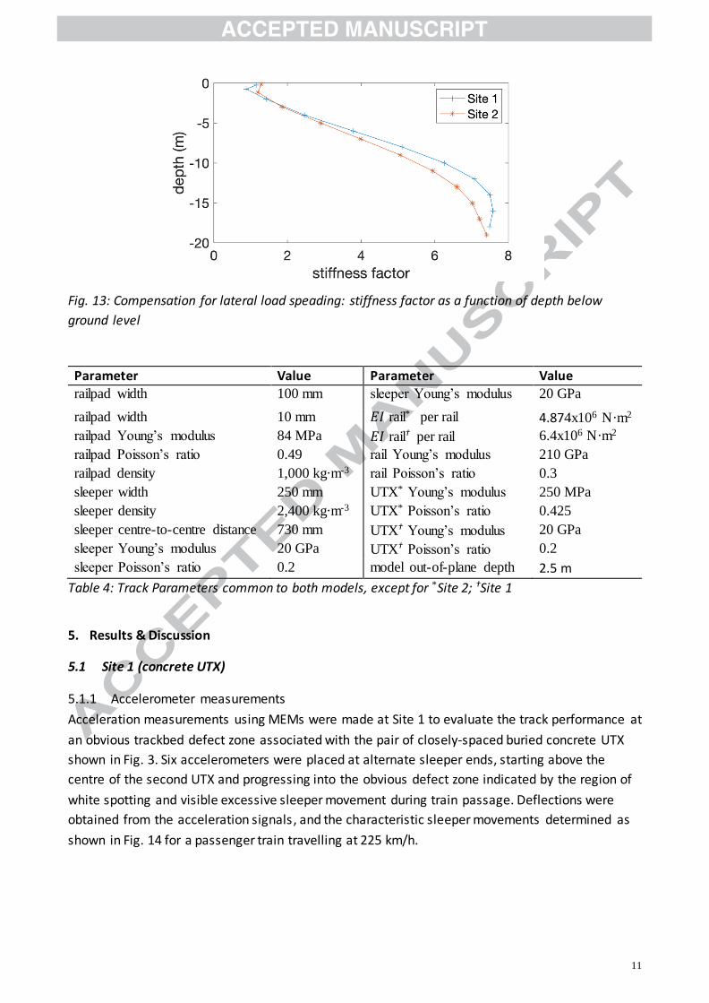
Adjustments were made to the Young’s moduli of the track substructure components (ballast, sub-
base and sublayers) to account for out-of-plane stress redistribution (lateral spreading), as follows.
Comparisons were made with an equivalent 3D model of a short length of track loaded vertically
by a single axle load. Using an iterative approach, similar to that proposed by Alves Ribeiro (2012),
the stiffnesses of the layers in the 2D model were altered until the vertical strains matched those
calculated in the 3D model at a range of depths below the wheel load. The resulting variation in
stiffness factor (defined as the ratio of the altered to the original stiffness) with depth is shown in
Figure 13: for each site model, the stiffnesses of the ground layers in the 2D models were
multiplied by these factors.
Two types of track condition were evaluated. Initially, each sleeper was modelled as being in
perfect contact with the underlying ballast, representing an idealised case with no initial
differential settlement or track geometry irregularities present. To evaluate the performance of
the track above the UTX in the conditions actually encountered in the field, a second model was
created in which gaps were imposed beneath selected sleepers near to the UTX to represent the
voiding measured in the field.

10
Fig. 11: Model schematic for Site 1: two concrete under-track crossings, each 2.4 m wide 0.3 m
deep, placed 4.9 m apart (7.3 m centre to centre), are shown below the ballast layer
(a)
(b)
Fig. 12: (a) Detail of plastic UTX cross-section (b) Model schematic for Site 2: a single plastic duct,
below the ballast layer
ballast
sub-grade
chalk
rail rail pads sleepers
UTX UTX4.9m
sub-ballast
376 mm
37
6 m
m
ballast
embankment
natural soil layer
rail rail pads sleepers
backfill ballast
UTX bedding
UTX
11
Fig. 13: Compensation for lateral load speading: stiffness factor as a function of depth below
ground level
Parameter Value Parameter Value
railpad width 100 mm sleeper Young’s modulus 20 GPa
railpad width 10 mm 𝐸𝐼 rail* per rail 4.874x10⁶ N·m2 railpad Young’s modulus 84 MPa 𝐸𝐼 rail† per rail 6.4x10⁶ N·m2
railpad Poisson’s ratio 0.49 rail Young’s modulus 210 GPa
railpad density 1,000 kg·m-3 rail Poisson’s ratio 0.3
sleeper width 250 mm UTX* Young’s modulus 250 MPa
sleeper density 2,400 kg·m-3 UTX* Poisson’s ratio 0.425
sleeper centre-to-centre distance 730 mm UTX† Young’s modulus 20 GPa
sleeper Young’s modulus 20 GPa UTX† Poisson’s ratio 0.2
sleeper Poisson’s ratio 0.2 model out-of-plane depth 2.5 m
Table 4: Track Parameters common to both models, except for *Site 2; †Site 1
5. Results & Discussion
5.1 Site 1 (concrete UTX)
5.1.1 Accelerometer measurements
Acceleration measurements using MEMs were made at Site 1 to evaluate the track performance at
an obvious trackbed defect zone associated with the pair of closely-spaced buried concrete UTX
shown in Fig. 3. Six accelerometers were placed at alternate sleeper ends, starting above the
centre of the second UTX and progressing into the obvious defect zone indicated by the region of
white spotting and visible excessive sleeper movement during train passage. Deflections were
obtained from the acceleration signals, and the characteristic sleeper movements determined as
shown in Fig. 14 for a passenger train travelling at 225 km/h.

12
Fig. 14: Sleeper movements at Site 1 determined using MEMS accelerometers
Fig. 14 shows that the measured track movements directly above the UTX were less than 1 mm,
but up to 8 mm in the defect zone beyond the second UTX. An understanding of the effects of the
UTX on the track behavior is needed to explain why the track has deteriorated at this location.
At Site 1, mechanized tamping was found to be consistently ineffective in removing the trackbed
fault, disturbing previously stable ballast and failing to repair the damaged zone. To try and
overcome this a revised maintenance method was implemented, using the accelerometer data to
inform local measured shovel packing. Lifting and packing was carried out to just beyond the
extent of the visible fault, with the lift and amount of new ballast placed calibrated to remove the
measured gap. Measurements following this intervention showed that it had been successful
(whereas tamping had not) in remediating the problem in the short and medium term. The vertical
dashed line in Fig. 15 indicates the timing of the maintenance intervention. Further details are
given in Milne et al (2018b).
Fig. 15: Daily mean sleeper movements before and after a maintenance intervention at the
locations / sleepers in Fig. 14
5.1.2 FEM simulation
To understand whether the high stiffness of the concrete UTX compared with the surrounding
ground was responsible for the large ranges of movement seen in the field, the FEM-based vehicle
/ track interaction model described earlier was used. Fig. 16 shows the sleeper movements
calculated for the idealized condition of perfect sleeper / subgrade contact, with the relative
-3 -2 -1 0 1 2 3 4 5 6 7 8
sleeper num ber
0
2
4
6
8
10
ma
xim
um
ve
rtic
al
sle
ep
er
dis
pla
ce
me
nt
(mm
)
UTX locations are
beneath sleepers
-13 to -10 (not plotted)
and sleepers -3 to 0

13
positions of the UTX indicated by hatching. In all simulations, the train travelled from left to right.
There is a modest reduction in displacement over the UTX compared with the free field, owing to
the increased effective stiffness of the ground above the UTX. However, this is negligible
compared with the factor of eight difference observed in the field. The contrast between the field
data and the calculations suggests that the difference in support stiffness between the natural
ground and the UTX does not directly account for the locally higher sleeper movements measured
beyond the end of the second UTX. An alternative explanation was therefore sought.
Fig. 16: FE VTI model of Site 1: sleeper movements for perfect sleeper / ballast contact
To evaluate the influence of the voiding shown to be present by visual observation and
accelerometer measurements, gaps between the sleepers and the trackbed were introduced into
the FEM simulation. The magnitudes of the gaps were adjusted until the pattern of sleeper
movements was similar to the general shape of the field measurements, as shown in Fig.17. The
FEM simulation represents a first approximation to the field behaviour, and could be refined to
match the field measurements more closely. However, the computational demand is not
insignificant and the reported simulation was considered to match the field behaviour sufficiently
closely for the purpose of demonstrating the probable cause of the behaviour observed. Thus it
appears that it is the presence of voided sleepers that leads to the differential track movements
observed, rather than a difference in support stiffness in itself.
Fig. 17: Maximum sleeper movements after gaps were introduced into the FE VTI model
approximating movements at Site 1. UTX locations indicated by hatched blocks
-10 -5 0 5 10
sleeper num ber (zero above U TX ,
negative be fore , positive a fte r)
0
0.5
1
1 .5
2
2 .5
3
3 .5
ma
xim
um
ve
rtic
al
sle
ep
er
dis
pla
ce
me
nt
(mm
)
-10 -5 0 5 10
sleeper num ber
0
2
4
6
8
10
12
ma
xim
um
ve
rtic
al
sle
ep
er
dis
pla
ce
me
nt
(mm
)
M ax s leeper d isp lacem ent
P rescribed gap

14
The FEM simulation was used to assess the stresses transferred from the sleeper base to the
trackbed (averaged along a horizontal path 50 mm below the sleeper base and 400 mm in length).
These are shown in Fig. 18, for both gapped and ungapped cases. Without gaps, the variations in
stress are fairlysmall and are roughly correlated with the changes in stiffness of the trackbed (the
UTX are stiffer than the surrounding ground). The introduction of gapping at the sleepers over the
UTX causes peaks in the trackbed stress at each end of the fault.
Fig. 19 shows the corresponding maximum absolute sleeper accelerations ; these exhibit a
significant increase over the gapped region of track (to the right of the right-hand UTX). This can
be explained by the extra freedom of the rail and sleeper assembly in the gapped region, which
allows a loaded sleeper to accelerate faster before coming into contact with the ground, at which
point it experiences a sudden, peak, deceleration. However, the sleeper acceleration is not directly
correlated to the under-sleeper stress, which peaks two sleepers beyond the end of the
downstream UTX.
Fig. 18: FE VTI model of Site 1: vertical stresses beneath sleepers before and after the introduction
of gaps. UTX locations indicated by hatched blocks
Fig. 19: FE VTI model of Site 1: maximum (absolute) sleeper acceleration before and after the
introduction of gaps. UTX locations indicated by hatched blocks
The rate of development of permanent settlement might be expected to increase with increasing
sleeper stress; hence a consistently uneven stress distribution would eventually give rise to
-10 -5 0 5
sleeper num ber
0
20
40
60
80
100
ve
rtic
al
str
es
s r
an
ge
(kP
a)
w ith gap
no gap
-10 -5 0 5
sleeper num ber
0
20
40
60
80
ma
xim
um
sle
ep
er
ac
ce
lera
tio
n (
m/s
2) w ith gap
no gap

15
differential permanent settlements and a corresponding unevenness of the track. To capture this
effect in the finite element analysis would require a soil behavioural model that permitted the
development of (likely very small) incremental plastic strains in proportion to the load experienced
in each cycle, above a cyclic stress threshold.
5.2 Site 2 (flexible UTX)
5.2.1 Geophone measurements
Geophone measurements were made approximately one year after UTX installation at Site 2.
Fig. 20 shows the characteristic sleeper movements determined from geophones placed on a
sequence of 10 consecutive sleeper ends, centred on the UTX.
Fig. 20: Sleeper movements at Site 2 (flexible UTX)) determined from geophones
The measurements in Fig. 20 show that the sleepers located immediately over and adjacent to the
shallow flexible UTX were moving by up to 8 mm vertically, while the nearby track was
characterized by movements of typically 1 mm to 2 mm.
5.2.2 FEM simulation
As at Site 1, the FE VTI model was run initially for an idealized installation with perfect sleeper /
subgrade contact. Fig. 21 shows the sleeper movements calculated; again, there is no discernible
difference in movements between sleepers near or above the UTX and those further away.

16
Fig. 21: FE VTI model of Site 2: sleeper movements for perfect sleeper / ballast contact
Fig 22. Maximum sleeper movements after gaps had been introduced into FE VTI model
approximating the measured movements at Site 2
To evaluate the influence of the voiding indicated by the geophone measurements, gaps were
introduced into the FEM simulation between the sleepers and trackbed and their magnitudes
adjusted until the pattern of sleeper movements approximated the general shape of the field
measurements shown in Fig. 22.
The FEM simulation was also used to evaluate the average sleeper base stresses transferred into
the trackbed. Fig.23 shows the peak vertical trackbed stresses calculated with and without gaps.
There is a small (insignificant) increase in average stress above the UTX for the case without gaps.
The introduction of gaps results in a substantial reduction in stresses above the UTX and causes
significant peaks in stress on either side of the UTX.
Sleeper accelerations are plotted in Fig. 24. Variations in the ungapped case are modest; however,
the gaps result in large increases in acceleration in the gapped region, biased towards the
-10 -5 0 5 10
s leeper num ber (zero above U TX ,
negative be fo re , pos itive a fte r)
0
0.5
1
1 .5
2
2 .5
3
3 .5
ma
xim
um
ve
rtic
al
sle
ep
er
dis
pla
ce
me
nt
(mm
)
-10 -5 0 5 10
s leeper num ber (zero above U TX ,
negative be fo re , pos itive a fte r)
0
2
4
6
8
10
12
ma
xim
um
ve
rtic
al
sle
ep
er
dis
pla
ce
me
nt
(mm
)
M ax s leeper d isp lacem ent
P rescribed gap

17
downstream side of the UTX. Again, these can be attributed to the relative freedom of the
sleeper/rail assembly in this region giving rise to larger accelerations and decelerations.
Figs. 25 and 26 show a detail of the UTX region as the first train wheel arrives directly over the
UTX. In the ungapped case (Fig. 25), the vertical stress due to the load from the front bogie axles is
reasonably well distributed. However, the presence of gapping in Fig. 26 means that less load is
taken by the ground directly above the UTX; load is instead carried disproportionately by the
sleeper three removed from that above the UTX. This is consistent with the increased stress at
sleeper number -3 indicated in Fig. 23.
Fig. 23: FE VTI model of Site 2: vertical stresses before and after the introduction of gaps
Fig. 24: FE VTI model of Site 2: maximum (absolute) sleeper acceleration before and after the
introduction of gaps
-10 -5 0 5 10
sleeper num ber (zero above U TX ,
negative before , positive a fte r)
0
50
100
ve
rtic
al
str
es
s r
an
ge
(kP
a)
w ith gap
no gap
-10 -5 0 5 10
sleeper num ber (zero above U TX ,
negative before , positive a fte r)
0
10
20
30
40
ma
xim
um
sle
ep
er
ac
ce
lera
tio
n (
m/s
2)
w ith gap
no gap

18
Fig. 25: FE VTI model of Site 2: vertical stress magnitude without gaps
Fig. 26: FE VTI model of Site 2: vertical stress magnitude with sleeper gaps
At both of the locations investigated, significant variations in the deflections of sleepers as trains
passed were apparent in the vicinity of the UTX. In numerical analyses, a variation in the track
support stiffness between the UTX and the surrounding ground did not give anything like the
variation in track movements seen in the field. To replicate the observed variations in movement,
it was necessary to introduce gaps below certain sleepers in the analysis. This led to increases in
maximum sleeper accelerations and significant variations in under-sleeper stresses.
Tracking the development of differential settlements and voided sleepers in a numerical analysis
would require the use of a soil behavioural model in which plastic strains developed as a function
of the load above a cyclic stress threshold. The small differences in under-sleeper stress resulting
from the small differences in track support stiffness above and adjacent to the UTX could then

19
lead to the development of differential settlement and ultimately potentially gapping. However, it
is not clear that using the calculated stresses to drive plastic strain in this way would in the cases
considered result in the gaps developing in the locations observed. Clearly, the train / track /
subgrade / UTX interactions are complex in nature.
The general condition of the ballast and subgrade are further important considerations. At Site 1,
a measured local shovel packing approach, with the amount of lift informed by the track
deflections determined from accelerometer data, was successful in poviding a lasting repair to the
observed defects, whereas conventional tamping was not. In contrast to Site 1, the UTX at Site 2
was retro-fitted to an existing railway (during a full possession), by excavating down through the
trackbed. The trackbed material was probably replaced over the UTX in a considerably loosened
state. Although localized hand packing was then implemented on a number of occasions following
UTX installation, the material has continued to show signs of settlement as evidenced by the
voiding observed at the sleepers over the UTX. Given enough time / train passes the loosened
trackbed material may repack. However, unless this is combined with targeted repacking to place
material into the gap (as was implemented at site 1), continued poor performance is likely.
6. Conclusions and further discussion
6.1 Conclusions from measurements and analyses
Under-track crossings (UTX) are a feature of modern railways. They may either be constructed
prior to track laying, or retrofitted below an existing railway. Measurements made at two UTX
sites – one preconstructed in concrete and the other a retrofitted cellular composite structure –
indicated significant differences in sleeper deflections in the region of the UTX as trains passed.
Finite element analyses based on an initially correct track geometry, appropriate stiffnesses for
both the soils and the inclusions, and with the sleepers in contact with the ballast did not show the
measured variation in sleeper deflections at either site. To reproduce the measured pattern of
sleeper deflections, it was necessary to introduce gaps below certain sleepers in the finite element
analyses. The inference is that the measured pattern of sleeper deflections is a result of gaps
below the sleepers, rather than differences in the underlying support stiffness per se.
6.2 Further discussion
The question then arises as to how the gaps develop. In the case of the retrofitted UTX, the gaps
were probably a direct consequence of the installation itself, which has yet to bed in after a year
of train operation over it and several packing interventions. In the case of the pre-built UTX, the
most likely possibility is that the relatively small differences in dynamic load associated with
variations in support stiffness, coupled with the gradual build up of plastic strains in proportion to
the load in excess of a cyclic threshold stress, led to the development of differential permanent
settlements over time. However, the relatively simple soil behavioural model used in the analyses
would not reproduce this behaviour, and the observed patterns of voiding show that the train /
track / sub-base / UTX interactions are highly complex.
The finite element based vehicle / track interaction analyses do not show a clear causal
relationship between the observed track deterioration and the variation in support stiffness with

20
an ideally-installed UTX. However, this is potentially a result of the limitations of the soil
constitutive model used, which did not allow for the development of small incremental plastic
strains at each load cycle. Combined with small differencs in load associated with variations in
track support stiffness and vehicle dynamic effects, this could over many cycles lead to gapping at
certain sleepers, which is a major issue and cause of accelerated deterioration.
Trackbed faults associated with the pre-built UTX (Site 1) were successfully remediated by means
of targeted, local measured shovel packing, with the amount of lift informed by the track
deflections measured during train passage. Continuous tamping through the defect zone had
previously been ineffective. It has not been possibly to trial this approach in as forensic a manner
for the retrofitted UTX (Site 2), which continues to cause problems.
Further research is needed into the effects of different designs of UTX, installation methods and
maintenance regimes on the performance of the overlying track, and the development of models
that capture the full complexity of train / track / sub-base / UTX interaction.
7. Acknowledgements
The authors are grateful for the financial support of the Engineering and Physical Sciences
Research Council (EPSRC) through the Programme grants TRACK21 (EP/H044949/1), and Track to
the Future (EP/M025276/1) and for the financial support of Network Rail through the University
Research Partnership in Future Infrastructure Systems. This work would also not have been
possible without the kind assistance and advice given by a number of current and past Network
Rail and HS1 employees.
8. References
Dassault Systèmes (2014). Abaqus 6.14 Documentation. Simulia, Dassault Systèmes, France.
Alves Ribeiro, C. (2012) Transições Aterro - Estrutura em Linhas Ferroviárias de Alta Velocidade:
Análise Experimental e Numérica. University of Porto.
Bowness, D., Lock, A. C., Powrie, W., Priest, J. A. and Richards, D. J. (2007). Monitoring the
dynamic displacements of railway track. Proceedings of the Institution of Mechanical Engineers,
Part F (Journal of Rail and Rapid Transit), 221 (1), 13-22. DOI:10.1243/0954409JRRT51
British Geological Survey / NERC. (1999) Onshore Borehole scans.
www.mapapps2.bgs.ac.uk/geoindex (accessed May 2019)
Coelho, B., Hölscher, P., Priest, J., Powrie, W. and Barends, F. (2011) An assessment of transition
zone performance. Proceedings of the Institution of Mechanical Engineers, Part F (Journal of Rail
and Rapid Transit), 225 (2), 129-139. DOI:10.1177/09544097JRRT389
Cubis (2015) MULTIDuct Product Focus brochure [Online]. Available: www.cubisindustries.com.
Kabo, E. (2006) A numerical study of the lateral ballast resistance in railway tracks. Proceedings of
the Institution of Mechanical Engineers, Part F (Journal of Rail and Rapid Transit) , 220 (4), 425-
433. DOI:10.1243/0954409JRRT61

21
Kim, H., Saade, L., Weston, P. and Roberts, C. (2014) Measuring the deflection of a sequence of
sleepers at a transition zone. 6th IET Conference on Railway Condition Monitoring, Birmingham.
DOI:10.1049/cp.2014.1019
Lamas-Lopez, F., Alves-Fernandes, V., Cui, Y. J., Costa D’aguiar, S., Calon, N., Canou, J., Dupla, J. C.,
Tang, A. M. and Robinet, A. (2014) Assessment of the double integration method using
accelerometers data for conventional railway platforms. In Proceedings of the Second
International Conference on Railway Technology: Research, Development and Maintenance, 8-
11 April 2014. Ajaccio, France.
Le Pen, L., Milne, D., Thompson, D. and Powrie, W. (2016) Evaluating railway track support
stiffness from trackside measurements in the absence of wheel load data. Canadian Geotechnical
Journal 53 (7), 1156-1166. DOI:10.1139/cgj-2015-0268
Le Pen, L., Watson, G., Powrie, W., Yeo, G., Weston, P. and Roberts, C. (2014) The behaviour of
railway level crossings: Insights through field monitoring. Transportation Geotechnics, 1 (4), 201-
213. DOI:10.1016/j.trgeo.2014.05.002
Milne, D. R. M., Le Pen, L. M., Thompson, D. J. and Powrie, W. (2017) Properties of train load
frequencies and their applications. Journal of Sound and Vibration, 397 (9), 123-140
DOI:10.1016/j.jsv.2017.03.006
Milne, D., Le Pen, L., Watson, G., Thompson, D., Powrie, W., Hayward, M. and Morley, S. (2016)
Proving MEMS Technologies for Smarter Railway Infrastructure. Procedia Engineering 143, 1077-
1084. DOI:10.1016/j.proeng.2016.06.222
Milne, D., Le Pen, L., Thompson, D. J. and Powrie, W. (2018a) Automated processing of railway
track deflection signals obtained from velocity and acceleration measurements. Proceedings of
the Institution of Mechanical Engineers, Part F (Journal of Rail and Rapid Transit) .
DOI:10.1177/0954409718762172.
Milne, D., Le Pen, L. M., Watson, G. V. R., Thompson, D. J., Powrie, W., Hayward, M. and Morley, S.
(2018b). Monitoring and repair of isolated trackbed defects on a ballasted railway.
Transportation Geotechnics 17 (Part A), 61-68. DOI: 10.1016/j.trgeo.2018.09.002.
Mirza, A. Frid, A. Nielsen, J. C. O. and Jones C. J. C. (2010) Ground Vibration Induced by Railway
Traffic – The Influence of Vehicle Parameters. Noise and Vibration Mitigation for Rail
Transportation Systems: Proceedings of the 10th International Workshop on RailwayNoise,
Nagahama, Japan, 18–22 October 2010. 24 (4), 451-459. DOI:10.1007/978-4-431-53927-8_30
Mishra, D., Qian, Y., Huang, H. and Tutumluer, E. (2014) An integrated approach to dynamic
analysis of railroad track transitions behavior. Transportation Geotechnics 1 (4), 188-200. DOI: 10.1016/j.trgeo.2014.07.001
O'Riordan, N. and Phear, A. (2001) Design and construction control of ballasted track formation
and subgrade for high speed lines. In Proceedings of the International Conference Railway
Engineering 2001.
22
Paixao, A., Fortunato, E. and Calcada, R. (2013) Design and construction of backfills for railway
track transition zones. Proceedings of the Institution of Mechanical Engineers, Part F (Journal of
Rail and Rapid Transit) 229 (1), 58-70. DOI: 10.1177/0954409713499016
Paixão, A., Alves Ribeiro, C., Pinto, N., Fortunato, E. and Calçada, R. (2014) On the use of under
sleeper pads in transition zones at railway underpasses: experimental field testing. Structure and
Infrastructure Engineering, 11 (2), 112-128. DOI:10.1080/15732479.2013.850730
Powrie, W., Yang, L. A. and Clayton, C. R. I. (2007) Stress changes in the ground below ballasted
railway track during train passage. Proceedings of the Institution of Mechanical Engineers, Part F
(Journal of Rail and Rapid Transit), 221 (2), 247-62. DOI: 10.1243/0954409JRRT95
Ribeiro C.A., Paixão A., Fortunato E. and Calçada R. (2015) Under sleeper pads in transition zones
at railway underpasses: numerical modelling and experimental validation. Structure and
Infrastructure Engineering, 11 (11), 1432-1449. DOI: DOI:10.1080/15732479.2014.970203
Shahraki, M. and Witt, K.J. (2015) 3D modeling of transition zone between ballasted and ballastless
high-speed railway track. Journal of Traffic and Transportation Engineering 3 (4), 234-240.
DOI:10.17265/2328-2142/2015.04.005
TSWG (2016) A Guide to Track Stiffness, Edited by W. Powrie,& L Le Pen on behalf of the cross
industry track stiffness working group (TSWG). Southampton. Southampton, UK, University of
Southampton, UK, ISBN: 9780854329946.
Varandas J.N., Hölscher P. and Silva M.A.G. (2013) Settlement of ballasted track under traffic
loading: Application to transition zones. Proceedings of the Institution of Mechanical Engineers,
Part F (Journal of Rail and Rapid Transit) 228 (3), 242-259. DOI:10.1177/0954409712471610
Varandas, J.N., Paixão A., Fortunato E. and Hölscher, P. (2016). A numerical study on the stress
changes in the ballast due to train passages. Advances in Transportation Geotechnics 3. The 3rd
International Conference on Transportation Geotechnics (ICTG 2016) 143, 1169–1176.
DOI:10.1016/j.proeng.2016.06.127
Wheeler, L. N., Take, W. A. and Hoult, N. A. (2016) Measurement of rail deflection on soft
subgrades using DIC. Proceedings of the Institution of Civil Engineers - Geotechnical Engineering,
169(5), 383-398. DOI:10.1680/jgeen.15.00171
Yang, L., Powrie, W. and Priest, J. (2009) Dynamic stress analysis of a ballasted railway track bed
during train passage. Journal of Geotechnical and Geoenvironmental Engineering 135 (5), 680-
689. DOI:10.1061/(ASCE)GT.1943-5606.0000032
Zhang, S., Xiao, X., Wen, Z. and Jin, X. (2008). Effect of unsupported sleepers on wheel / rail normal
load. Soil Dynamics and Earthquake Engineering 28 (8), 662-673
Zhu, J.Y., Thompson, D. J. and Jones, C. J. C. (2011). On the effect of unsupported sleepers on the
dynamic behaviour of a railway track. Vehicle System Dynamics 49 (9), 1389-1408