Embed Size (px)
Citation preview
9(2012) 643 – 656
Field investigation on variation of rail support modulus in bal-lasted railway tracks
Abstract
Rail support modulus is an important factor in safety of
railway track. This parameter is defined as support force
imposing on rail length unit per rail unit displacement in
vertical direction. Rail support modulus is important be-
cause it affects track performance and maintenance require-
ments. Both low and large modulus is undesirable. Low
modulus of the rail support has been shown to cause differ-
ential settlement that then increases maintenance needs. On
the other hand, higher value of rail support causes axle load
to be distributed on fewer sleepers and therefore received
dynamic loads for any sleeper and rail-sleeper fastening will
be increased. Sandy desert areas are critical regions about
the contamination of ballast. In these areas, flowing sand
grains influence between ballast aggregates and increase the
stiffness of ballast layer and the rail support modulus. In
this paper, the results of a field investigation about the ef-
fect of ballast contamination on the values of the rail support
modulus in sandy desert areas are presented.
Keywords
Rail support modulus, Railway in sandy areas, ballast con-
tamination
Jabbar Ali Zakeria,∗ andRauf Abbasib
aAssociate Professor, School of Railway Engi-
neering, , Iran University of Science and Tech-
nology, Iran.
Tel.:+98 21 7724 0100, Fax:+98 21 7745 1568bMaster of Science, School of Railway Engi-
neering, Iran University of Science and Tech-
nology
Received 30 Apr 2011;In revised form 21 May 2012
∗ Author email: [email protected]
1 INTRODUCTION
Track quality plays an important role in railway safety. One of the affecting factors of track
quality is the track stiffness. Track stiffness is defined as proportion factor between rail vertical
displacement and vertical contact pressure between rail base and track foundation. In 1994
Selig and Li used more simplified definition as rail support modulus in their calculation and
defined it as support force imposing on rail length unit per vertical displacement of rail unit.
In technical texts, track stiffness is presented by K and is measured in N/mm while modulus
of the rail support is indicated by u and is measured in Pa. In addition to above mentioned
difference, the main difference between track stiffness and rail support modulus is that track
modulus takes effects of flexural stiffness of rail, EI (rail dimensions and material determine
EI ), while u depends on other components of superstructure such as sleeper and rail-sleeper
Latin American Journal of Solids and Structures 9(2012) 643 – 656
644 J.A. Zakeri et al / Field investigation on variation of rail support modulus in ballasted railway tracks
fastening system and infrastructure such as ballast, sub-ballast and soil subgrade layer. Thus
rail support modulus is independent from rail type [2, 7, 15].
Rail support modulus is a major parameter because it affects track performance and main-
tenance requirements. Both low and large modulus is undesirable. Low modulus of the rail
support has been shown to cause differential settlement that then increases maintenance needs
[6]. On the other hand, if the variation of rail support modulus is too high, as in bridge vicinity
and slab tracks, dynamic forces imposed on track increase. Higher value of rail support modu-
lus leads to reduction of deflections and stresses in the track but on the other hand, this issue
causes axle load to be distributed over fewer sleepers and therefore received share of axle load
for any sleeper and rail-sleeper fastening force will increase [19, 21]. Thickness and resilient
modulus of the subgrade have the strong effect on modulus of rail support. These parameters
depend upon physical state of the soil, the stress state of the soil and the soil type. Ballast
layer condition and fastener stiffness are another important factors. Increasing the width of
ballast shoulder and or increasing fastener stiffness will increase rail support modulus [11].
Another numerous factors affect on resilient modulus of ballast and consequently on the
rail support modulus such as maximum grain size, aggregate type, particle shape, moisture
content and ballast breakage index (BBI) [8].
Ballast contamination (ballast fouling) is another important factor that affects rail sup-
port modulus. Sandy desert regions are critical areas about this issue. In these areas, flowing
sand grains penetrate between ballast aggregates and increase ballast layer stiffness and conse-
quently rail support modulus increases. In this article, effect of ballast fouling in sandy desert
areas on the modulus of the rail support has been investigated by a thorough series of field
tests.
2 THE METHODS FOR MEASUREMENT OF THE RAIL SUPPORT MODULUS
Different methods have been proposed for measurement and calculation of rail support modulus
and track stiffness. These methods can be classified generally in 3 major groups: theoretical,
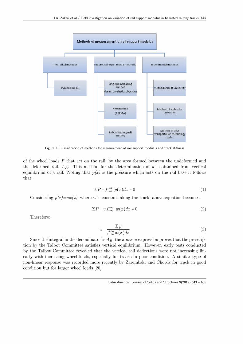
theoretical-experimental and experimental. Fig. 1 shows the summary of this classification.
Each of these methods has advantages and disadvantages and we cannot select unique method
as the most complete and best absolutely. Theoretical methods are questionable about validity
and on the other hand, generally, there are many problems with experimental methods about
their field tests and they lead to very high time and costs consuming. Therefore, the widespread
use of these experimental methods is not possible for all railroads and in all places [10].
2.1 Talbot-Wasiutynski method
Talbot-Wasiutynski method has been used in this field investigation for calculation of the
rail support modulus. This method was proposed and used by Talbot committee [3] and by
Wasiutynski [16]. In this method a car is moved to the track location of test and the caused
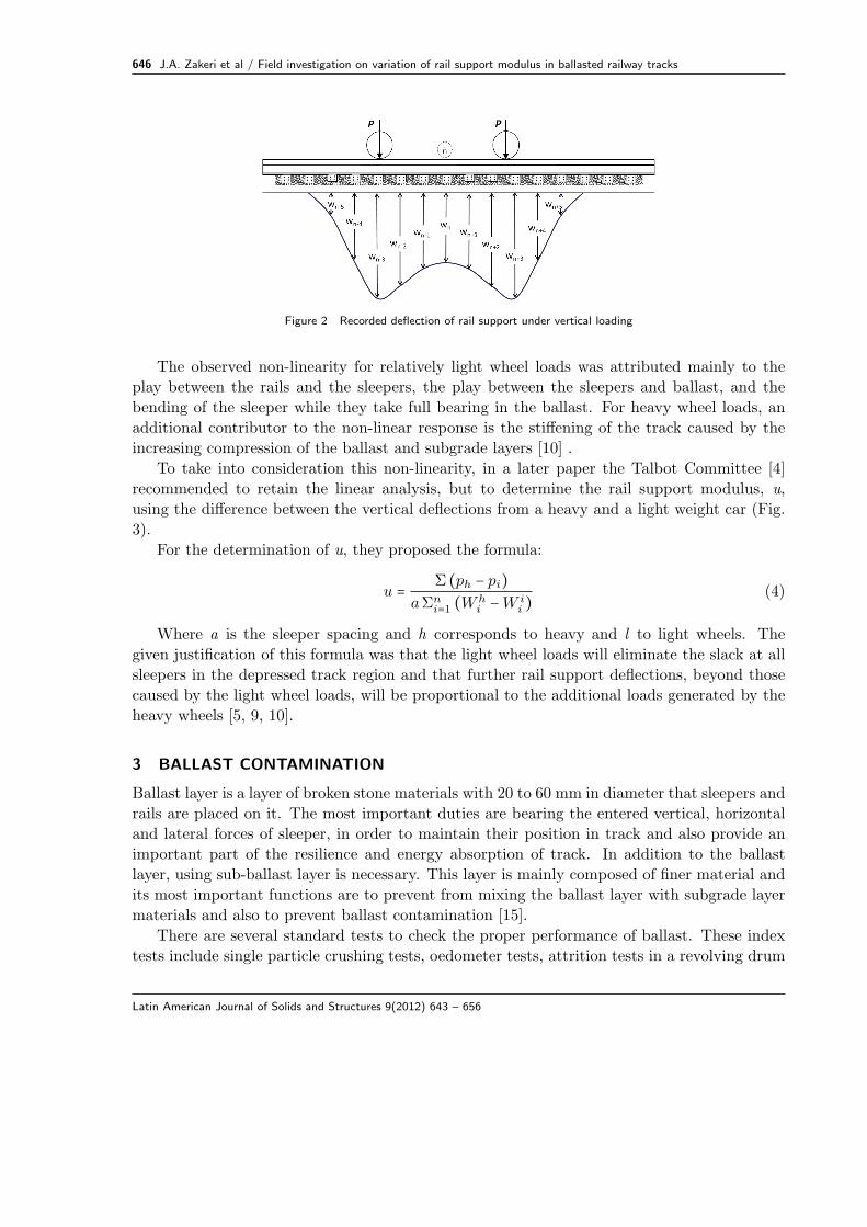
vertical rail support deflection at each sleeper are measured, as shown in Fig. 2 [6].
According to this method, the rail support modulus, u, is calculated by dividing the sum
Latin American Journal of Solids and Structures 9(2012) 643 – 656
J.A. Zakeri et al / Field investigation on variation of rail support modulus in ballasted railway tracks 645
Figure 1 Classification of methods for measurement of rail support modulus and track stiffness
of the wheel loads P that act on the rail, by the area formed between the undeformed and
the deformed rail, AR. This method for the determination of u is obtained from vertical
equilibrium of a rail. Noting that p(x) is the pressure which acts on the rail base it follows
that:
ΣP − ∫+∞−∞ p(x)dx = 0 (1)
Considering p(x)=uw(x), where u is constant along the track, above equation becomes:
ΣP − u ∫+∞−∞ w(x)dx = 0 (2)
Therefore:
u = Σp
∫+∞−∞w(x)dx(3)
Since the integral in the denominator is AR, the above u expression proves that the prescrip-
tion by the Talbot Committee satisfies vertical equilibrium. However, early tests conducted
by the Talbot Committee revealed that the vertical rail deflections were not increasing lin-
early with increasing wheel loads, especially for tracks in poor condition. A similar type of
non-linear response was recorded more recently by Zarembski and Chords for track in good
condition but for larger wheel loads [20].
Latin American Journal of Solids and Structures 9(2012) 643 – 656
646 J.A. Zakeri et al / Field investigation on variation of rail support modulus in ballasted railway tracks
Figure 2 Recorded deflection of rail support under vertical loading
The observed non-linearity for relatively light wheel loads was attributed mainly to the
play between the rails and the sleepers, the play between the sleepers and ballast, and the
bending of the sleeper while they take full bearing in the ballast. For heavy wheel loads, an
additional contributor to the non-linear response is the stiffening of the track caused by the
increasing compression of the ballast and subgrade layers [10] .
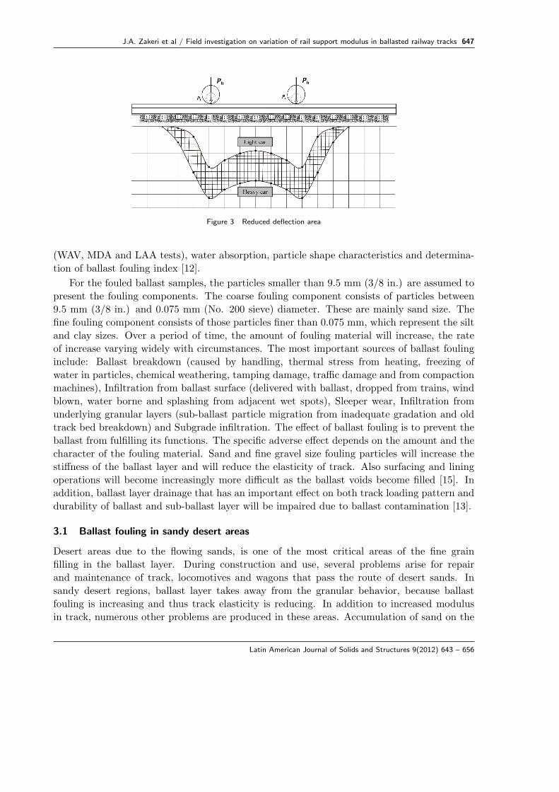
To take into consideration this non-linearity, in a later paper the Talbot Committee [4]
recommended to retain the linear analysis, but to determine the rail support modulus, u,
using the difference between the vertical deflections from a heavy and a light weight car (Fig.
3).
For the determination of u, they proposed the formula:
u = Σ (ph − pi)aΣn
i=1 (Whi −W i
i )(4)
Where a is the sleeper spacing and h corresponds to heavy and l to light wheels. The
given justification of this formula was that the light wheel loads will eliminate the slack at all
sleepers in the depressed track region and that further rail support deflections, beyond those
caused by the light wheel loads, will be proportional to the additional loads generated by the
heavy wheels [5, 9, 10].
3 BALLAST CONTAMINATION
Ballast layer is a layer of broken stone materials with 20 to 60 mm in diameter that sleepers and
rails are placed on it. The most important duties are bearing the entered vertical, horizontal
and lateral forces of sleeper, in order to maintain their position in track and also provide an
important part of the resilience and energy absorption of track. In addition to the ballast
layer, using sub-ballast layer is necessary. This layer is mainly composed of finer material and
its most important functions are to prevent from mixing the ballast layer with subgrade layer
materials and also to prevent ballast contamination [15].
There are several standard tests to check the proper performance of ballast. These index
tests include single particle crushing tests, oedometer tests, attrition tests in a revolving drum
Latin American Journal of Solids and Structures 9(2012) 643 – 656
J.A. Zakeri et al / Field investigation on variation of rail support modulus in ballasted railway tracks 647
Figure 3 Reduced deflection area
(WAV, MDA and LAA tests), water absorption, particle shape characteristics and determina-
tion of ballast fouling index [12].
For the fouled ballast samples, the particles smaller than 9.5 mm (3/8 in.) are assumed to
present the fouling components. The coarse fouling component consists of particles between
9.5 mm (3/8 in.) and 0.075 mm (No. 200 sieve) diameter. These are mainly sand size. The
fine fouling component consists of those particles finer than 0.075 mm, which represent the silt
and clay sizes. Over a period of time, the amount of fouling material will increase, the rate
of increase varying widely with circumstances. The most important sources of ballast fouling
include: Ballast breakdown (caused by handling, thermal stress from heating, freezing of
water in particles, chemical weathering, tamping damage, traffic damage and from compaction
machines), Infiltration from ballast surface (delivered with ballast, dropped from trains, wind
blown, water borne and splashing from adjacent wet spots), Sleeper wear, Infiltration from
underlying granular layers (sub-ballast particle migration from inadequate gradation and old
track bed breakdown) and Subgrade infiltration. The effect of ballast fouling is to prevent the
ballast from fulfilling its functions. The specific adverse effect depends on the amount and the
character of the fouling material. Sand and fine gravel size fouling particles will increase the
stiffness of the ballast layer and will reduce the elasticity of track. Also surfacing and lining
operations will become increasingly more difficult as the ballast voids become filled [15]. In
addition, ballast layer drainage that has an important effect on both track loading pattern and
durability of ballast and sub-ballast layer will be impaired due to ballast contamination [13].
3.1 Ballast fouling in sandy desert areas
Desert areas due to the flowing sands, is one of the most critical areas of the fine grain
filling in the ballast layer. During construction and use, several problems arise for repair
and maintenance of track, locomotives and wagons that pass the route of desert sands. In
sandy desert regions, ballast layer takes away from the granular behavior, because ballast
fouling is increasing and thus track elasticity is reducing. In addition to increased modulus
in track, numerous other problems are produced in these areas. Accumulation of sand on the
Latin American Journal of Solids and Structures 9(2012) 643 – 656
648 J.A. Zakeri et al / Field investigation on variation of rail support modulus in ballasted railway tracks
concrete sleeper, leads to the chemical reaction of salt (in the sand) and concrete and finally
destruction and corrosion of concrete. Also in desert regions, rails and other metal equipment
of track are placed in the vicinity of salty sand and this issue leads to corrosion of rails and
metal instruments of track pavement. Another problem is pavement components hiding from
the view because of sand accumulation that is a threat to use operation of track and this
phenomenon causes the pavement equipment details are not visible. Other problems occurred
for track in these areas include: Crushing rail crown and therefore being flattened rail head due
to reduced track elasticity, Increase of track maintenance activities and consequently increase
of maintenance costs, Rails buckling due to temperature fluctuations much higher than the
neutral temperature, Switch function reduction caused by sand accumulation and Different
alignment levels of rails due to unequal quenched of two rails [17].
4 FIELD MEASUREMENT METHODOLOGY
A thorough field investigation is conducted in this research. The main objectives of the field
tests include:
• Determination of the ballast contamination in sandy desert areas (at four points).
• Determination of rail support modulus at test points using vertical deflection values of
track and by the method of Talbot-Wasiutynski.
• Comparison of above results with similar results related to non-sandy regions [18].
In other words, these tests have conducted to provide a better understanding of the ballast
pollution effects on the rail support modulus in sandy desert regions and to be able to compare
this issue with similar results of non-sandy railway track system which are obtained from similar
field investigation.
The test site is located in a block of east district of Iran railway networking that is a critical
area of the flowing sand. The tests have been conducted in four different locations and with
different granular contamination of ballast to be examined the effects of the percentage of
pollution on the rail support modulus.
The properties of the track in the field are as follows. Rail is UIC60; sleeper is pre-stressed
concrete sleeper type B70; sleeper distance is 60 cm; the fastening system is Vossloh; ballast
and sub-ballast thicknesses are 30 and 15 centimeters, respectively; ballast aggregates are
Granite with a size of 20 to 60 mm.
To measure the values of track vertical deflection in order to determine the rail support
modulus, several LVDT equipments are installed at the end of the adjacent sleepers (according
to method of Talbot-Wasiutynski). Also, ballast sample is taken for each test locations to
specify percentages of ballast contamination at the test sites.
Latin American Journal of Solids and Structures 9(2012) 643 – 656
J.A. Zakeri et al / Field investigation on variation of rail support modulus in ballasted railway tracks 649
4.1 LVDT equipments installation
The linear variable differential transformer (LVDT) is a type of electrical transformer used for
very accurate measuring of linear displacement. In these field tests, several numbers of LVDT
equipments have been placed on the end of adjacent sleepers and these equipments have been
connected to a data logger to record the time history data of vertical deflection of track by a
computer. The used data logger is capable to record up to 2000 data per second.
LVDTs are very accurate and sensitive tools and for using, they must be firmly fixed in the
desired place to measure the displacements accurately. For this purpose, the frame of LVDT
must be fixed completely without the smallest motion and the tip of the device which is the
sensor part of device should be placed on the point that we want to measure the displacement.
This part of device has the freedom to move inside and outside and thus, positive and negative
displacements can be measured.
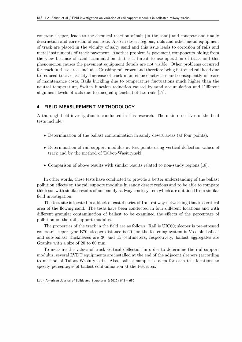
To fix the LVDTs, the special steel bases have been prepared in the required number. As
can be seen in the Fig. 4, these bases have a plate on their ends which is placed perpendicular
to the arm. The frame of the LVDT is attached to this plate and its tip is placed on the end of
concrete sleeper to measure the vertical deflection of track. The frame of LVDT is connected
by special plastic bases with glue on the mentioned plate. To fix the steel bases, their vertical
arm is buried inside the trench in the vicinity of ballast shoulder to a height of 0.5 meter
approximately and around soil is compacted. The metal horns located at the end of vertical
bases can help to further stabilize of the bases inside the soil.
Figure 4 How to put the LVDT devices in tests place, using steel bases
4.2 Ballast sampling at test locations
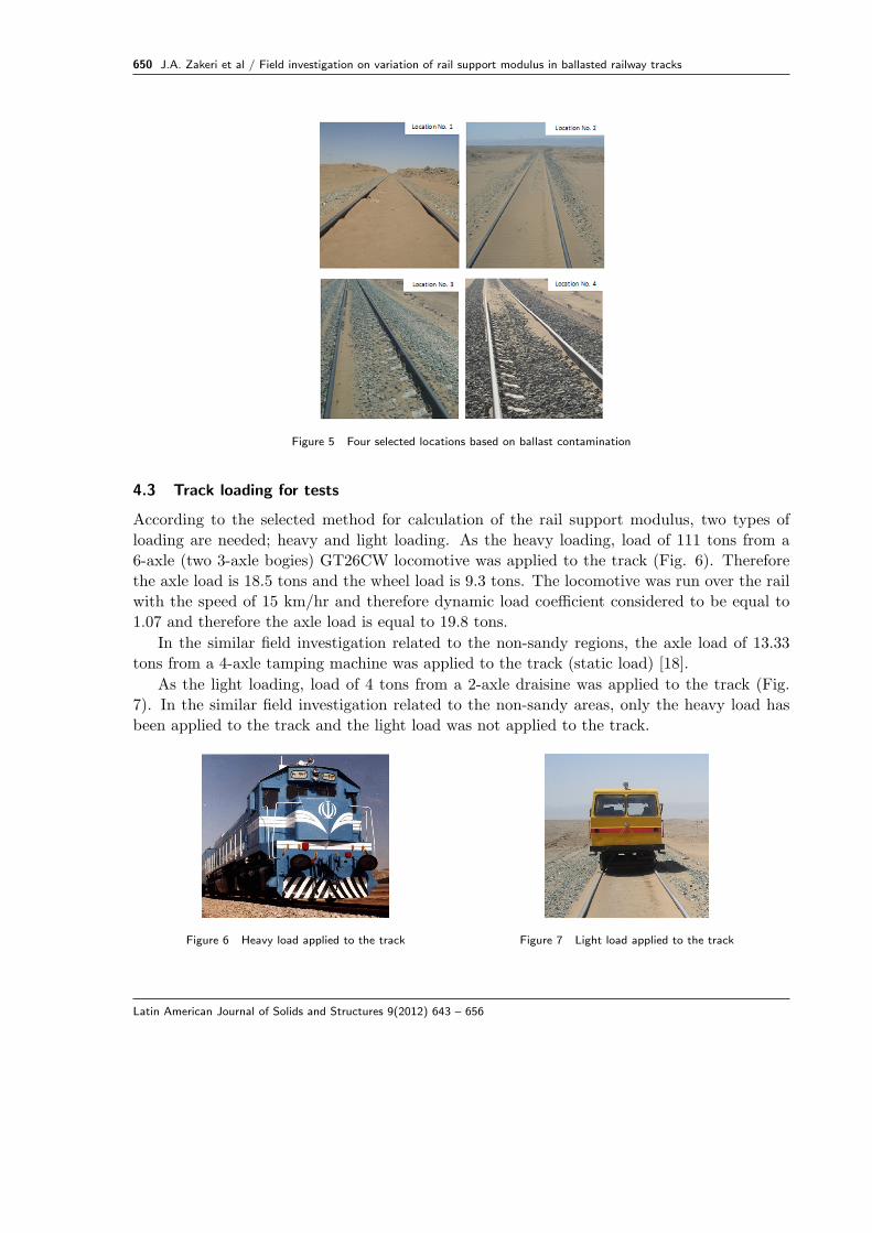
In each four test sites, the ballast was sampled and particle size analysis has been taken on
these samples. Fig. 5 Shows image of the test locations. Ballast sampling was performed
according to ASTM-C136 standard. Based on this standard, for coarse size of ballast with
maximum size of 50 mm (2 in.), about 20 kg sampling should be done. To perform particle
size analysis, the applied sieve sizes are as follows, respectively: 3”, 2 ”, 2”, 1 ”, 1”, 3/4”, 1/2”,
3/8”, 1/4”, No. 4, No. 6, No. 10, No. 20 and No. 40 [1].
Latin American Journal of Solids and Structures 9(2012) 643 – 656
650 J.A. Zakeri et al / Field investigation on variation of rail support modulus in ballasted railway tracks
Figure 5 Four selected locations based on ballast contamination
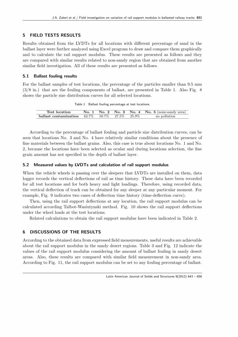
4.3 Track loading for tests
According to the selected method for calculation of the rail support modulus, two types of
loading are needed; heavy and light loading. As the heavy loading, load of 111 tons from a
6-axle (two 3-axle bogies) GT26CW locomotive was applied to the track (Fig. 6). Therefore
the axle load is 18.5 tons and the wheel load is 9.3 tons. The locomotive was run over the rail
with the speed of 15 km/hr and therefore dynamic load coefficient considered to be equal to
1.07 and therefore the axle load is equal to 19.8 tons.
In the similar field investigation related to the non-sandy regions, the axle load of 13.33
tons from a 4-axle tamping machine was applied to the track (static load) [18].
As the light loading, load of 4 tons from a 2-axle draisine was applied to the track (Fig.
7). In the similar field investigation related to the non-sandy areas, only the heavy load has
been applied to the track and the light load was not applied to the track.
Figure 6 Heavy load applied to the track Figure 7 Light load applied to the track
Latin American Journal of Solids and Structures 9(2012) 643 – 656
J.A. Zakeri et al / Field investigation on variation of rail support modulus in ballasted railway tracks 651
5 FIELD TESTS RESULTS
Results obtained from the LVDTs for all locations with different percentage of sand in the
ballast layer were further analyzed using Excel program to draw and compare them graphically
and to calculate the rail support modulus. These results are presented as follows and they
are compared with similar results related to non-sandy region that are obtained from another
similar field investigation. All of these results are presented as follows.
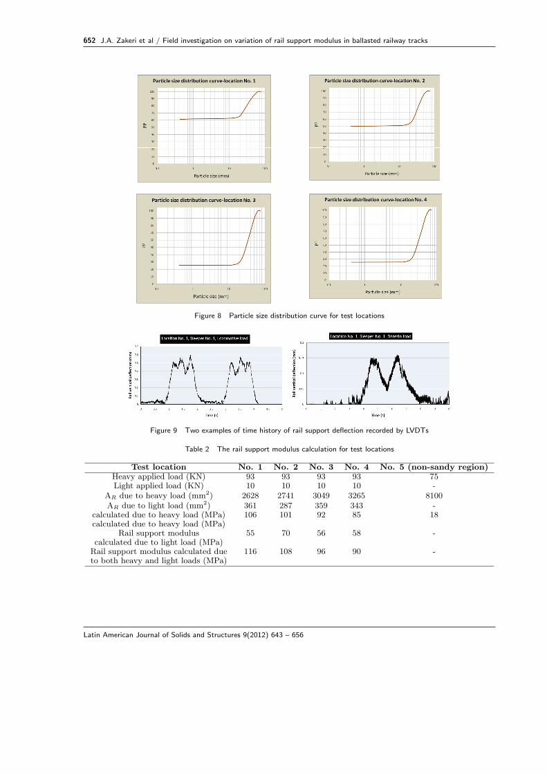
5.1 Ballast fouling results
For the ballast samples of test locations, the percentage of the particles smaller than 9.5 mm
(3/8 in.) that are the fouling components of ballast, are presented in Table 1. Also Fig. 8
shows the particle size distribution curves for all selected locations.
Table 1 Ballast fouling percentage at test locations.
Test location No. 1 No. 2 No. 3 No. 4 No. 5 (none-sandy area)ballast contamination 62.7% 50.7% 27.5% 25.9% no pollution
According to the percentage of ballast fouling and particle size distribution curves, can be
seen that locations No. 3 and No. 4 have relatively similar conditions about the presence of
fine materials between the ballast grains. Also, this case is true about locations No. 1 and No.
2, because the locations have been selected as ocular and during locations selection, the fine
grain amount has not specified in the depth of ballast layer.
5.2 Measured values by LVDTs and calculation of rail support modulus
When the vehicle wheels is passing over the sleepers that LVDTs are installed on them, data
logger records the vertical deflections of rail as time history. These data have been recorded
for all test locations and for both heavy and light loadings. Therefore, using recorded data,
the vertical deflection of track can be obtained for any sleeper at any particular moment. For
example, Fig. 9 indicates two cases of deflection time history (time-deflection curve).
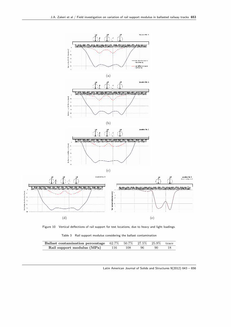
Then, using the rail support deflections at any location, the rail support modulus can be
calculated according Talbot-Wasiutynski method. Fig. 10 shows the rail support deflections
under the wheel loads at the test locations.
Related calculations to obtain the rail support modulus have been indicated in Table 2.
6 DISCUSSIONS OF THE RESULTS
According to the obtained data from expressed field measurements, useful results are achievable
about the rail support modulus in the sandy desert regions. Table 3 and Fig. 12 indicate the
values of the rail support modulus considering the amount of ballast fouling in sandy desert
areas. Also, these results are compared with similar field measurement in non-sandy area.
According to Fig. 11, the rail support modulus can be set to any fouling percentage of ballast.
Latin American Journal of Solids and Structures 9(2012) 643 – 656
652 J.A. Zakeri et al / Field investigation on variation of rail support modulus in ballasted railway tracks
Figure 8 Particle size distribution curve for test locations
Figure 9 Two examples of time history of rail support deflection recorded by LVDTs
Table 2 The rail support modulus calculation for test locations
Test location No. 1 No. 2 No. 3 No. 4 No. 5 (non-sandy region)Heavy applied load (KN) 93 93 93 93 75Light applied load (KN) 10 10 10 10 -
AR due to heavy load (mm2) 2628 2741 3049 3265 8100AR due to light load (mm2) 361 287 359 343 -
calculated due to heavy load (MPa) 106 101 92 85 18calculated due to heavy load (MPa)
Rail support modulus 55 70 56 58 -calculated due to light load (MPa)
Rail support modulus calculated due 116 108 96 90 -to both heavy and light loads (MPa)
Latin American Journal of Solids and Structures 9(2012) 643 – 656
J.A. Zakeri et al / Field investigation on variation of rail support modulus in ballasted railway tracks 653
(a)
(b)
(c)
(d) (e)
Figure 10 Vertical deflections of rail support for test locations, due to heavy and light loadings.
Table 3 Rail support modulus considering the ballast contamination
Ballast contamination percentage 62.7% 50.7% 27.5% 25.9% trace
Rail support modulus (MPa) 116 108 96 90 18
Latin American Journal of Solids and Structures 9(2012) 643 – 656
654 J.A. Zakeri et al / Field investigation on variation of rail support modulus in ballasted railway tracks
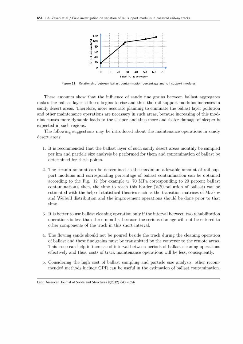
020406080100120 0 10 20 30 40 50 60 70Rail bed modulus (MPa) Ballast fouling percentageFigure 11 Relationship between ballast contamination percentage and rail support modulus
These amounts show that the influence of sandy fine grains between ballast aggregates
makes the ballast layer stiffness begins to rise and thus the rail support modulus increases in
sandy desert areas. Therefore, more accurate planning to eliminate the ballast layer pollution
and other maintenance operations are necessary in such areas, because increasing of this mod-
ulus causes more dynamic loads to the sleeper and thus more and faster damage of sleeper is
expected in such regions.
The following suggestions may be introduced about the maintenance operations in sandy
desert areas:
1. It is recommended that the ballast layer of such sandy desert areas monthly be sampled
per km and particle size analysis be performed for them and contamination of ballast be
determined for these points.
2. The certain amount can be determined as the maximum allowable amount of rail sup-
port modulus and corresponding percentage of ballast contamination can be obtained
according to the Fig. 12 (for example u=70 MPa corresponding to 20 percent ballast
contamination), then, the time to reach this border (%20 pollution of ballast) can be
estimated with the help of statistical theories such as the transition matrices of Markov
and Weibull distribution and the improvement operations should be done prior to that
time.
3. It is better to use ballast cleaning operation only if the interval between two rehabilitation
operations is less than three mouths, because the serious damage will not be entered to
other components of the track in this short interval.
4. The flowing sands should not be poured beside the track during the cleaning operation
of ballast and these fine grains must be transmitted by the conveyor to the remote areas.
This issue can help in increase of interval between periods of ballast cleaning operations
effectively and thus, costs of track maintenance operations will be less, consequently.
5. Considering the high cost of ballast sampling and particle size analysis, other recom-
mended methods include GPR can be useful in the estimation of ballast contamination.
Latin American Journal of Solids and Structures 9(2012) 643 – 656
J.A. Zakeri et al / Field investigation on variation of rail support modulus in ballasted railway tracks 655
6. Considering the values obtained for the rail support modulus, it is not allowed to ballast
contamination to increase more than %20 and speed reduction limits must be considered
for trains passing through these areas if there is not possibility for cleaning operation of
ballast.
7. Tests results show that despite previous assumptions about changes in the modulus of
the rail support, the increase in this parameter even for not too much contamination of
ballast layer is very high and thus special planning is needed for maintenance operations
of track in such sandy desert areas.
7 CONCLUSION
In this paper the results of a field investigation about the ballast contamination percentage
and the values of the rail support modulus in sandy desert areas presented. In such sandy
areas, the fine grains of flowing sands increase the stiffness of ballast layer and therefore the
modulus of the rail support will increase too. Considering the amount of ballast fouling, four
different locations are selected for tests. One another point, related to non-sandy area in a
similar field tests, is considered as the fifth location and the results of sandy desert areas are
compared with this result of non-sandy area.
Ballast contaminations in four selected locations are %62.7, %50.7, %27.5 and %25.9, and
there is no pollution for the fifth point.
Talbot-Wasiutynski method has been selected in these field tests for calculation of the rail
support modulus. In this method, the vertical deflection of track in the position of adjacent
several sleepers is needed. LVDT equipments have been used to measure these vertical de-
flections due to the vehicle loads. In Talbot-Wasiutynski method two types of loading must
be used; heavy and light. Heavy loading is done by GT26CW locomotive and a draisine has
been used for light loading. According to this method, the obtained values of the rail support
modulus for test locations are 116, 108, 96 and 90 MPa respectively, and for non-sandy location
this modulus value is 18 MPa.
These results indicate that despite previous assumptions about changes in the modulus
of the rail support, the increase in this parameter even for not too much contamination of
ballast layer is very high and therefore the special precision must be provided in planning of
maintenance operations of such sandy areas, because increasing of the rail support modulus
leads to increasing of applied dynamic load and thus more and faster damage is expected for
sleepers in such areas.
Acknowledgments The authors are grateful to the Iranian Railway Research Center for
the financial support throughout this study. The authors would like to thank the technical
Engineers, Sh. Homavandi and H. Mohammadvand, for their assistance during the course of
this project. Also, authors wish to thank Engineers M. Moeeni and H. Mortazavi for their
helps and suggestions.
Latin American Journal of Solids and Structures 9(2012) 643 – 656
656 J.A. Zakeri et al / Field investigation on variation of rail support modulus in ballasted railway tracks
References[1] ASTM, american society for testing and materials. c136-96 a. Standard Test Method for Sieve Analysis of Fine and
Coarse Aggregates.
[2] Z. Cai, G. P. Raymond, and R. J. Bathurst. Estimate of static track modulus using elastic foundation models.Transportation Research Record, 1470:65–72, 1994.
[3] Talbot Committee. Asce-area committee on stresses in railroad tracks, 1918. First Progress Report, ProceedingsAREA.
[4] Talbot Committee. Asce-area committee on stresses in railroad tracks. volume 35, 1933. Sixth Progress Report,Proceedings AREA.
[5] S. Crawford, M. Murray, and J. Powell. Development of a mechanistic model for the determination of track modulus.In 7th International Heavy Haul Conference, Brisbane, Australia, 2001.
[6] W. Ebersohn, M. C. Trevizo, and E. T. Selig. Effect of low track modulus on track performance. In InternationalHeavy Haul Association, Proc. Of Fifth International Heavy Haul Conference, pages 379–388, 1993.
[7] S. Farritor, R. Arnold, and S. Lu. On board measurement of vertical track modulus. September 2006.
[8] B. Indraratna, J. S. Vinod, and J. Lackenby. Influence of particle breakage on the resilient modulus of railway ballast.Journal of Geotechnique, 59(7):643–646, 2008.
[9] A. D. Kerr. On the determination of the rail support modulus k. International Journal of Solids and Structures,37:4335–4351, 2000.
[10] A. D. Kerr. Fundamentals of Railway Track Engineering. Simmons-Boardman Books, Inc, 2003.
[11] D. Li and E. T. Selig. Resilient modulus for fine grained subgrade soils. Journal of Geotechnical Engineering, ASCE,120(6):939–957, 1994.
[12] G. R. McDowell, W. L. lim, A. C. Collop, R. Armitage, and N. H. Thom. Comparison of ballast index tests forrailway trackbeds. In Proceeding of the ICE, Journal of Geotechnical Engineering, volume 157, pages 151–161,Nonember-Desember 2004.
[13] K. R. Rushton and G. Ghataora. Understanding and modeling drainage of railway ballast. In Proceedings of theICE, Journal of Transport, volume 162, pages 227–236, 2009.
[14] E. T. Selig and D. Li. Track modulus: It’s meaning and factors influencing it. Transportation Research Record,1470:47–54, 1994.
[15] E. T. Selig and J. M. Waters. Track geotechnology and substructure management. 1994. University of MassachusettsUSA.
[16] A. Wasiutynski. „recherches experimentales sur les deformations elastiques et le travail de la superstructure deschemins de fer„ (experimantal research on the elastic deformations and stresses in a railroad track, in french).Annales de L’Academie des Sciences Techniques a Varsavie, IV, 1937.
[17] J. A. Zakeri and R. Abbasi. Field investigation on distribution of contact pressure between sleeper and saturatedballast with flowing sand. In 11th International Conference of Railway Engineering, London, 2011.
[18] J. A. Zakeri and J. Sadeghi. Field investigation on load distribution and deflections of railway track sleepers. Journalof Mechanical Science and Technology, 21:1948–1956, 2007.
[19] J. A. Zakeri, H. Xia, and J. J. Fan. Dynamic responses of train -track system to single rail irregularity. LatinAmerican Journal of Solids and Structures, 6(2):89–104, 2009.
[20] A. M. Zarembski and J. Choros. On the Measurement and Calculation of Vertical Track Modulus. Nonember-Desember 1979. AREA BULLETION 675.
[21] A. M. Zarembski and J. Palese. Transitions eliminate impact at crossings. Railway Track and Structures, August2003.
Latin American Journal of Solids and Structures 9(2012) 643 – 656