Embed Size (px)
Citation preview
35011386 05/2009
3501
1386
.04
www.schneider-electric.com
TwidoSuite V2.2Programming Guide
05/2009

Schneider Electric assumes no responsibility for any errors that may appear in this document. If you have any suggestions for improvements or amendments or have found errors in this publication, please notify us.
No part of this document may be reproduced in any form or by any means, electronic or mechanical, including photocopying, without express written permission of Schneider Electric.
All pertinent state, regional, and local safety regulations must be observed when installing and using this product. For reasons of safety and to help ensure compliance with documented system data, only the manufacturer should perform repairs to components.
When devices are used for applications with technical safety requirements, the relevant instructions must be followed.
Failure to use Schneider Electric software or approved software with our hardware products may result in injury, harm, or improper operating results.
Failure to observe this information can result in injury or equipment damage.
© 2009 Schneider Electric. All rights reserved.
2 35011386 05/2009
Table of Contents
Safety Information . . . . . . . . . . . . . . . . . . . . . . . . . . . . . . 11About the Book . . . . . . . . . . . . . . . . . . . . . . . . . . . . . . . . . 13
Part I Description of Twido Software . . . . . . . . . . . . . . . . . 15Chapter 1 Introduction to TwidoSuite . . . . . . . . . . . . . . . . . . . . . . . 17
Introduction to TwidoSuite. . . . . . . . . . . . . . . . . . . . . . . . . . . . . . . . . . . . . 18Introduction to Twido Languages . . . . . . . . . . . . . . . . . . . . . . . . . . . . . . . 19
Chapter 2 Twido Language Objects . . . . . . . . . . . . . . . . . . . . . . . . 23Language Object Validation . . . . . . . . . . . . . . . . . . . . . . . . . . . . . . . . . . . 24Bit Objects . . . . . . . . . . . . . . . . . . . . . . . . . . . . . . . . . . . . . . . . . . . . . . . . . 25Word Objects. . . . . . . . . . . . . . . . . . . . . . . . . . . . . . . . . . . . . . . . . . . . . . . 27Floating Point and Double Word Objects . . . . . . . . . . . . . . . . . . . . . . . . . 30Addressing Bit Objects . . . . . . . . . . . . . . . . . . . . . . . . . . . . . . . . . . . . . . . 34Addressing Word Objects . . . . . . . . . . . . . . . . . . . . . . . . . . . . . . . . . . . . . 35Addressing Floating Objects . . . . . . . . . . . . . . . . . . . . . . . . . . . . . . . . . . . 36Addressing Double Word Objects . . . . . . . . . . . . . . . . . . . . . . . . . . . . . . . 37Addressing Inputs/Outputs . . . . . . . . . . . . . . . . . . . . . . . . . . . . . . . . . . . . 38Network Addressing . . . . . . . . . . . . . . . . . . . . . . . . . . . . . . . . . . . . . . . . . 41Function Block Objects . . . . . . . . . . . . . . . . . . . . . . . . . . . . . . . . . . . . . . . 42Structured Objects. . . . . . . . . . . . . . . . . . . . . . . . . . . . . . . . . . . . . . . . . . . 44Indexed Objects . . . . . . . . . . . . . . . . . . . . . . . . . . . . . . . . . . . . . . . . . . . . 48Symbolizing Objects . . . . . . . . . . . . . . . . . . . . . . . . . . . . . . . . . . . . . . . . . 50
Chapter 3 User Memory . . . . . . . . . . . . . . . . . . . . . . . . . . . . . . . . . . 51User Memory Structure . . . . . . . . . . . . . . . . . . . . . . . . . . . . . . . . . . . . . . . 52Backup and Restore without Backup Cartridge or Extended Memory . . . 55Backup and Restore with a 32K Backup Cartridge . . . . . . . . . . . . . . . . . . 57Using the 64K Extended Memory Cartridge . . . . . . . . . . . . . . . . . . . . . . . 60
Chapter 4 Event task management. . . . . . . . . . . . . . . . . . . . . . . . . . 63Overview of Event Tasks. . . . . . . . . . . . . . . . . . . . . . . . . . . . . . . . . . . . . . 64Description of Different Event Sources . . . . . . . . . . . . . . . . . . . . . . . . . . . 65Event Management . . . . . . . . . . . . . . . . . . . . . . . . . . . . . . . . . . . . . . . . . . 67
35011386 05/2009 3
Part II Special Functions . . . . . . . . . . . . . . . . . . . . . . . . . . . 69Chapter 5 Communications . . . . . . . . . . . . . . . . . . . . . . . . . . . . . . . . 71
Presentation of the Different Types of Communication . . . . . . . . . . . . . . 72TwidoSuite to Controller Communication. . . . . . . . . . . . . . . . . . . . . . . . . 74Communication between TwidoSuite and a Modem . . . . . . . . . . . . . . . . 81Remote Link Communications. . . . . . . . . . . . . . . . . . . . . . . . . . . . . . . . . 93ASCII Communications . . . . . . . . . . . . . . . . . . . . . . . . . . . . . . . . . . . . . . 106Modbus Communications . . . . . . . . . . . . . . . . . . . . . . . . . . . . . . . . . . . . 117Standard Modbus Requests . . . . . . . . . . . . . . . . . . . . . . . . . . . . . . . . . . 134Modbus Function Codes 23 (MB FC) - Read/Write Multiple registers and N Words. . . . . . . . . . . . . . . . . . . . . . . . . . . . . . . . . . . . . . . . . . . . . . . . . . 140Modbus Function Codes 43/14 (MB FC) - Read Device Identification . . 143Transparent Ready Implementation Class (Twido Serial A05, Ethernet A15) . . . . . . . . . . . . . . . . . . . . . . . . . . . . . . . . . . . . . . . . . . . . . . . . . . . . . 147
Chapter 6 Built-In Analog Functions . . . . . . . . . . . . . . . . . . . . . . . . 149Analog potentiometer. . . . . . . . . . . . . . . . . . . . . . . . . . . . . . . . . . . . . . . . 150Analog Channel . . . . . . . . . . . . . . . . . . . . . . . . . . . . . . . . . . . . . . . . . . . . 152
Chapter 7 Managing Analog Modules . . . . . . . . . . . . . . . . . . . . . . . 155Analog Module Overview. . . . . . . . . . . . . . . . . . . . . . . . . . . . . . . . . . . . . 156Addressing Analog Inputs and Outputs . . . . . . . . . . . . . . . . . . . . . . . . . . 157Configuring Analog Inputs and Outputs. . . . . . . . . . . . . . . . . . . . . . . . . . 159Analog Module Status Information. . . . . . . . . . . . . . . . . . . . . . . . . . . . . . 166Example of Using Analog Modules . . . . . . . . . . . . . . . . . . . . . . . . . . . . . 168
Chapter 8 Twido Extreme Input/Output Configuration . . . . . . . . . . 1718.1 An Introduction to Twido Extreme Inputs and Outputs . . . . . . . . . . . . . . 172
Twido Extreme Addressing Inputs/Outputs (I/O) . . . . . . . . . . . . . . . . . . . 1728.2 Twido Extreme Input Configuration . . . . . . . . . . . . . . . . . . . . . . . . . . . . . 175
Twido Extreme Discrete Input Configuration . . . . . . . . . . . . . . . . . . . . . . 176Twido Extreme Analog Input Configuration . . . . . . . . . . . . . . . . . . . . . . . 181Twido Extreme PWM Input Configuration . . . . . . . . . . . . . . . . . . . . . . . . 186Twido Extreme PWM Input Configuration Example. . . . . . . . . . . . . . . . . 188
8.3 Twido Extreme Output Configuration. . . . . . . . . . . . . . . . . . . . . . . . . . . . 194Twido Extreme Discrete Output Configuration. . . . . . . . . . . . . . . . . . . . . 195Twido Extreme Pulse (PLS) Generator Output Configuration . . . . . . . . . 198Twido Extreme PWM Output Configuration in Standard Mode . . . . . . . . 205Twido Extreme PWM Output Configuration in Hydraulic Mode . . . . . . . . 214Twido Extreme Hydraulic PWM Output Configuration Example . . . . . . . 222
Chapter 9 Installing the AS-Interface V2 bus . . . . . . . . . . . . . . . . . . 225Presentation of the AS-Interface V2 Bus . . . . . . . . . . . . . . . . . . . . . . . . . 226General Functional Description . . . . . . . . . . . . . . . . . . . . . . . . . . . . . . . . 227Software Set up Principles. . . . . . . . . . . . . . . . . . . . . . . . . . . . . . . . . . . . 230Description of the Configuration Screen for the AS-Interface Bus. . . . . . 232Configuration of the AS-Interface Bus . . . . . . . . . . . . . . . . . . . . . . . . . . . 234Description of the AS-Interface Window in Online Mode. . . . . . . . . . . . . 240
4 35011386 05/2009
Modification of Slave Address . . . . . . . . . . . . . . . . . . . . . . . . . . . . . . . . . . 244Updating the AS-Interface Bus Configuration in Online Mode . . . . . . . . . 246Automatic Addressing of an AS-Interface V2 Slave . . . . . . . . . . . . . . . . . 250How to insert a Slave Device into an Existing AS-Interface V2 Configuration . . . . . . . . . . . . . . . . . . . . . . . . . . . . . . . . . . . . . . . . . . . . . . . 251Automatic Configuration of a Replaced AS-Interface V2 Slave . . . . . . . . 252Addressing I/Os Associated with Slave Devices Connected to the AS-Interface V2 Bus . . . . . . . . . . . . . . . . . . . . . . . . . . . . . . . . . . . . . . . . . . . . 253Programming and Diagnostics for the AS-Interface V2 Bus . . . . . . . . . . . 255AS-Interface V2 Bus Interface Module Operating Mode: . . . . . . . . . . . . . 260
Chapter 10 Installing and Configuring the CANopen Fieldbus . . . . 26110.1 CANopen Fieldbus Overview . . . . . . . . . . . . . . . . . . . . . . . . . . . . . . . . . . 262
CANopen Knowledge Base. . . . . . . . . . . . . . . . . . . . . . . . . . . . . . . . . . . . 263About CANopen . . . . . . . . . . . . . . . . . . . . . . . . . . . . . . . . . . . . . . . . . . . . 264CANOpen Boot-Up . . . . . . . . . . . . . . . . . . . . . . . . . . . . . . . . . . . . . . . . . . 267Process Data Object (PDO) Transmission . . . . . . . . . . . . . . . . . . . . . . . . 270Access to Data by Explicit Exchanges (SDO) . . . . . . . . . . . . . . . . . . . . . . 272"Node Guarding" and "Life Guarding" . . . . . . . . . . . . . . . . . . . . . . . . . . . . 273Internal Bus Management . . . . . . . . . . . . . . . . . . . . . . . . . . . . . . . . . . . . . 275
10.2 Implementing the CANopen Bus. . . . . . . . . . . . . . . . . . . . . . . . . . . . . . . . 276Overview . . . . . . . . . . . . . . . . . . . . . . . . . . . . . . . . . . . . . . . . . . . . . . . . . . 277Hardware Setup . . . . . . . . . . . . . . . . . . . . . . . . . . . . . . . . . . . . . . . . . . . . 279CANOpen Configuration - Default Parameter . . . . . . . . . . . . . . . . . . . . . . 280Configuration Methodology . . . . . . . . . . . . . . . . . . . . . . . . . . . . . . . . . . . . 284Declaration of a CANopen Master. . . . . . . . . . . . . . . . . . . . . . . . . . . . . . . 286CANopen Configuration Tool . . . . . . . . . . . . . . . . . . . . . . . . . . . . . . . . . . 287CANopen Network Slave Declaration . . . . . . . . . . . . . . . . . . . . . . . . . . . . 292CANopen Objects Mapping (Slaves). . . . . . . . . . . . . . . . . . . . . . . . . . . . . 300CANopen Objects Linking (Master). . . . . . . . . . . . . . . . . . . . . . . . . . . . . . 304CANopen Objects Symbols. . . . . . . . . . . . . . . . . . . . . . . . . . . . . . . . . . . . 307Addressing PDOs of the CANopen master . . . . . . . . . . . . . . . . . . . . . . . . 308Programming and diagnostics for the CANopen fieldbus . . . . . . . . . . . . . 310CANopen Hot Swap for Twido Controllers . . . . . . . . . . . . . . . . . . . . . . . . 317
Chapter 11 Installing and Configuring the CANJ1939 Fieldbus . . . 31811.1 CANJ1939 Fieldbus Overview . . . . . . . . . . . . . . . . . . . . . . . . . . . . . . . . . 319
CANJ1939 Knowledge Base. . . . . . . . . . . . . . . . . . . . . . . . . . . . . . . . . . . 320CANJ19139 Parameter Group Number and Suspect Parameter Number 322CANJ1939 Identifier . . . . . . . . . . . . . . . . . . . . . . . . . . . . . . . . . . . . . . . . . 323Communication on a CANJ1939 Network. . . . . . . . . . . . . . . . . . . . . . . . . 325
11.2 Implementing the CANJ1939 Bus . . . . . . . . . . . . . . . . . . . . . . . . . . . . . . . 326CANJ1939 Implementation Overview . . . . . . . . . . . . . . . . . . . . . . . . . . . . 327Hardware Setup . . . . . . . . . . . . . . . . . . . . . . . . . . . . . . . . . . . . . . . . . . . . 328CANJ1939 Configuration Methodology . . . . . . . . . . . . . . . . . . . . . . . . . . . 329CANJ1939 Configuration Dialog Boxes (Element, Network, Port) . . . . . . 332Creating or Deleting CANJ1939 Transmit/Receive Objects . . . . . . . . . . . 335
35011386 05/2009 5
Viewing CANJ1939 Transmit/Receive objects. . . . . . . . . . . . . . . . . . . . . 343CANJ1939 Broadcast Configuration . . . . . . . . . . . . . . . . . . . . . . . . . . . . 346CANJ1939 Peer-to Peer Configuration . . . . . . . . . . . . . . . . . . . . . . . . . . 348CANJ1939 Configuration in Expert Mode . . . . . . . . . . . . . . . . . . . . . . . . 350CANJ1939 Input/Output Objects . . . . . . . . . . . . . . . . . . . . . . . . . . . . . . . 352Request a PGN Output . . . . . . . . . . . . . . . . . . . . . . . . . . . . . . . . . . . . . . 356
Chapter 12 Configuring the TwidoPort Ethernet Gateway . . . . . . . . 36012.1 Normal Configuration and Connection of TwidoPort . . . . . . . . . . . . . . . . 361
Normal Configuration with TwidoSuite. . . . . . . . . . . . . . . . . . . . . . . . . . . 362BootP Configuration. . . . . . . . . . . . . . . . . . . . . . . . . . . . . . . . . . . . . . . . . 369
12.2 TwidoPort’s Telnet Configuration. . . . . . . . . . . . . . . . . . . . . . . . . . . . . . . 370Introducing Telnet Configuration . . . . . . . . . . . . . . . . . . . . . . . . . . . . . . . 371Telnet Main Menu . . . . . . . . . . . . . . . . . . . . . . . . . . . . . . . . . . . . . . . . . . 372IP/Ethernet Settings. . . . . . . . . . . . . . . . . . . . . . . . . . . . . . . . . . . . . . . . . 373Serial Parameter Configuration . . . . . . . . . . . . . . . . . . . . . . . . . . . . . . . . 374Configuring the Gateway . . . . . . . . . . . . . . . . . . . . . . . . . . . . . . . . . . . . . 375Security Configuration . . . . . . . . . . . . . . . . . . . . . . . . . . . . . . . . . . . . . . . 377Ethernet Statistics . . . . . . . . . . . . . . . . . . . . . . . . . . . . . . . . . . . . . . . . . . 378Serial Statistics . . . . . . . . . . . . . . . . . . . . . . . . . . . . . . . . . . . . . . . . . . . . 379Saving the Configuration . . . . . . . . . . . . . . . . . . . . . . . . . . . . . . . . . . . . . 380Restoring Default Settings . . . . . . . . . . . . . . . . . . . . . . . . . . . . . . . . . . . . 381Upgrading the TwidoPort Firmware . . . . . . . . . . . . . . . . . . . . . . . . . . . . . 382Forgot Your Password and/or IP Configuration? . . . . . . . . . . . . . . . . . . . 384
12.3 Communication Features. . . . . . . . . . . . . . . . . . . . . . . . . . . . . . . . . . . . . 385Ethernet Features . . . . . . . . . . . . . . . . . . . . . . . . . . . . . . . . . . . . . . . . . . 386Modbus/TCP Communications Protocol . . . . . . . . . . . . . . . . . . . . . . . . . 387Locally Supported Modbus Function Codes . . . . . . . . . . . . . . . . . . . . . . 388
Chapter 13 Operator Display Operation . . . . . . . . . . . . . . . . . . . . . . . 390Operator Display . . . . . . . . . . . . . . . . . . . . . . . . . . . . . . . . . . . . . . . . . . . 391Controller Identification and State Information. . . . . . . . . . . . . . . . . . . . . 394System Objects and Variables. . . . . . . . . . . . . . . . . . . . . . . . . . . . . . . . . 396Serial Port Settings . . . . . . . . . . . . . . . . . . . . . . . . . . . . . . . . . . . . . . . . . 403Time of Day Clock . . . . . . . . . . . . . . . . . . . . . . . . . . . . . . . . . . . . . . . . . . 404Real-Time Correction Factor . . . . . . . . . . . . . . . . . . . . . . . . . . . . . . . . . . 405
Part III Description of Twido Languages . . . . . . . . . . . . . . 408Chapter 14 Ladder Language . . . . . . . . . . . . . . . . . . . . . . . . . . . . . . . 410
Introduction to Ladder Diagrams . . . . . . . . . . . . . . . . . . . . . . . . . . . . . . . 411Programming Principles for Ladder Diagrams. . . . . . . . . . . . . . . . . . . . . 413Ladder Diagram Blocks . . . . . . . . . . . . . . . . . . . . . . . . . . . . . . . . . . . . . . 415Ladder Language Graphic Elements . . . . . . . . . . . . . . . . . . . . . . . . . . . . 418Special Ladder Instructions OPEN and SHORT . . . . . . . . . . . . . . . . . . . 421
6 35011386 05/2009
Programming Advice . . . . . . . . . . . . . . . . . . . . . . . . . . . . . . . . . . . . . . . . . 423Ladder/List Reversibility . . . . . . . . . . . . . . . . . . . . . . . . . . . . . . . . . . . . . . 428Guidelines for Ladder/List Reversibility . . . . . . . . . . . . . . . . . . . . . . . . . . . 430Program Documentation . . . . . . . . . . . . . . . . . . . . . . . . . . . . . . . . . . . . . . 432
Chapter 15 Instruction List Language . . . . . . . . . . . . . . . . . . . . . . . . 434Overview of List Programs . . . . . . . . . . . . . . . . . . . . . . . . . . . . . . . . . . . . 435Operation of List Instructions. . . . . . . . . . . . . . . . . . . . . . . . . . . . . . . . . . . 437List Language Instructions . . . . . . . . . . . . . . . . . . . . . . . . . . . . . . . . . . . . 438Using Parentheses . . . . . . . . . . . . . . . . . . . . . . . . . . . . . . . . . . . . . . . . . . 441Stack Instructions (MPS, MRD, MPP). . . . . . . . . . . . . . . . . . . . . . . . . . . . 444
Chapter 16 Grafcet . . . . . . . . . . . . . . . . . . . . . . . . . . . . . . . . . . . . . . . 446Description of Grafcet Instructions . . . . . . . . . . . . . . . . . . . . . . . . . . . . . . 447Description of Grafcet Program Structure . . . . . . . . . . . . . . . . . . . . . . . . . 452Actions Associated with Grafcet Steps . . . . . . . . . . . . . . . . . . . . . . . . . . . 455
Part IV Description of Instructions and Functions . . . . . . . 458Chapter 17 Basic Instructions . . . . . . . . . . . . . . . . . . . . . . . . . . . . . . 460
17.1 Boolean Processing . . . . . . . . . . . . . . . . . . . . . . . . . . . . . . . . . . . . . . . . . 461Boolean Instructions . . . . . . . . . . . . . . . . . . . . . . . . . . . . . . . . . . . . . . . . . 462Understanding the Format for Describing Boolean Instructions . . . . . . . . 464Load Instructions (LD, LDN, LDR, LDF) . . . . . . . . . . . . . . . . . . . . . . . . . . 466Assignment instructions (ST, STN, R, S) . . . . . . . . . . . . . . . . . . . . . . . . . 468Logical AND Instructions (AND, ANDN, ANDR, ANDF) . . . . . . . . . . . . . . 470Logical OR Instructions (OR, ORN, ORR, ORF). . . . . . . . . . . . . . . . . . . . 472Exclusive OR, instructions (XOR, XORN, XORR, XORF). . . . . . . . . . . . . 474NOT Instruction (N) . . . . . . . . . . . . . . . . . . . . . . . . . . . . . . . . . . . . . . . . . . 476
17.2 Basic Function Blocks . . . . . . . . . . . . . . . . . . . . . . . . . . . . . . . . . . . . . . . . 478Basic Function Blocks . . . . . . . . . . . . . . . . . . . . . . . . . . . . . . . . . . . . . . . . 479Standard function blocks programming principles. . . . . . . . . . . . . . . . . . . 481Timer Function Block (%TMi) . . . . . . . . . . . . . . . . . . . . . . . . . . . . . . . . . . 483TOF Type of Timer . . . . . . . . . . . . . . . . . . . . . . . . . . . . . . . . . . . . . . . . . . 485TON Type of Timer . . . . . . . . . . . . . . . . . . . . . . . . . . . . . . . . . . . . . . . . . . 486TP Type of Timer. . . . . . . . . . . . . . . . . . . . . . . . . . . . . . . . . . . . . . . . . . . . 487Programming and Configuring Timers . . . . . . . . . . . . . . . . . . . . . . . . . . . 488Up/Down Counter Function Block (%Ci) . . . . . . . . . . . . . . . . . . . . . . . . . . 491Programming and Configuring Counters. . . . . . . . . . . . . . . . . . . . . . . . . . 494Shift Bit Register Function Block (%SBRi) . . . . . . . . . . . . . . . . . . . . . . . . 496Step Counter Function Block (%SCi) . . . . . . . . . . . . . . . . . . . . . . . . . . . . 499
17.3 Numerical Processing . . . . . . . . . . . . . . . . . . . . . . . . . . . . . . . . . . . . . . . . 502Introduction to Numerical Instructions . . . . . . . . . . . . . . . . . . . . . . . . . . . . 503Assignment Instructions . . . . . . . . . . . . . . . . . . . . . . . . . . . . . . . . . . . . . . 504Comparison Instructions . . . . . . . . . . . . . . . . . . . . . . . . . . . . . . . . . . . . . . 509Arithmetic Instructions on Integers . . . . . . . . . . . . . . . . . . . . . . . . . . . . . . 511
35011386 05/2009 7
Logic Instructions. . . . . . . . . . . . . . . . . . . . . . . . . . . . . . . . . . . . . . . . . . . 514Shift Instructions . . . . . . . . . . . . . . . . . . . . . . . . . . . . . . . . . . . . . . . . . . . 516Conversion Instructions . . . . . . . . . . . . . . . . . . . . . . . . . . . . . . . . . . . . . . 518Single/Double Word Conversion Instructions . . . . . . . . . . . . . . . . . . . . . 520
17.4 Program Instructions . . . . . . . . . . . . . . . . . . . . . . . . . . . . . . . . . . . . . . . . 522END Instructions . . . . . . . . . . . . . . . . . . . . . . . . . . . . . . . . . . . . . . . . . . . 523NOP Instruction . . . . . . . . . . . . . . . . . . . . . . . . . . . . . . . . . . . . . . . . . . . . 525Jump Instructions. . . . . . . . . . . . . . . . . . . . . . . . . . . . . . . . . . . . . . . . . . . 526Subroutine Instructions . . . . . . . . . . . . . . . . . . . . . . . . . . . . . . . . . . . . . . 528
Chapter 18 Advanced Instructions . . . . . . . . . . . . . . . . . . . . . . . . . . . 53018.1 Advanced Function Blocks. . . . . . . . . . . . . . . . . . . . . . . . . . . . . . . . . . . . 531
Bit and Word Objects Associated with Advanced Function Blocks . . . . . 532Programming Principles for Advanced Function Blocks . . . . . . . . . . . . . 534LIFO/FIFO Register Function Block (%Ri). . . . . . . . . . . . . . . . . . . . . . . . 536LIFO Operation . . . . . . . . . . . . . . . . . . . . . . . . . . . . . . . . . . . . . . . . . . . . 538FIFO Operation . . . . . . . . . . . . . . . . . . . . . . . . . . . . . . . . . . . . . . . . . . . . 539Programming and Configuring Registers. . . . . . . . . . . . . . . . . . . . . . . . . 540Pulse Width Modulation Function Block (%PWM) . . . . . . . . . . . . . . . . . . 543Pulse Generator Output Function Block (%PLS). . . . . . . . . . . . . . . . . . . 547Drum Controller Function Block (%DR) . . . . . . . . . . . . . . . . . . . . . . . . . . 550Drum Controller Function Block %DRi Operation . . . . . . . . . . . . . . . . . . 552Programming and Configuring Drum Controllers. . . . . . . . . . . . . . . . . . . 554Fast Counter Function Block (%FC) . . . . . . . . . . . . . . . . . . . . . . . . . . . . 556Very Fast Counter Function Block (%VFC) . . . . . . . . . . . . . . . . . . . . . . . 559Transmitting/Receiving Messages - the Exchange Instruction (EXCH). . 574Exchange Control Function Block (%MSGx) . . . . . . . . . . . . . . . . . . . . . . 575
18.2 Clock Functions . . . . . . . . . . . . . . . . . . . . . . . . . . . . . . . . . . . . . . . . . . . . 579Clock Functions . . . . . . . . . . . . . . . . . . . . . . . . . . . . . . . . . . . . . . . . . . . . 580Schedule Blocks . . . . . . . . . . . . . . . . . . . . . . . . . . . . . . . . . . . . . . . . . . . 581Time/Date Stamping . . . . . . . . . . . . . . . . . . . . . . . . . . . . . . . . . . . . . . . . 584Setting the Date and Time . . . . . . . . . . . . . . . . . . . . . . . . . . . . . . . . . . . . 586
18.3 Twido PID Quick Start Guide. . . . . . . . . . . . . . . . . . . . . . . . . . . . . . . . . . 590Purpose of Document . . . . . . . . . . . . . . . . . . . . . . . . . . . . . . . . . . . . . . . 591Step 1 - Configuration of Analog Channels Used for Control . . . . . . . . . 593Step 2 - Prerequisites for PID Configuration . . . . . . . . . . . . . . . . . . . . . . 595Step 3 – Configuring the PID . . . . . . . . . . . . . . . . . . . . . . . . . . . . . . . . . . 597Step 4 - Initialization of Control Set-Up . . . . . . . . . . . . . . . . . . . . . . . . . . 603Step 5 - Control Set-Up AT + PID . . . . . . . . . . . . . . . . . . . . . . . . . . . . . . 608Step 6 - Debugging Adjustments . . . . . . . . . . . . . . . . . . . . . . . . . . . . . . . 612
18.4 PID Function . . . . . . . . . . . . . . . . . . . . . . . . . . . . . . . . . . . . . . . . . . . . . . 614Overview . . . . . . . . . . . . . . . . . . . . . . . . . . . . . . . . . . . . . . . . . . . . . . . . . 615Principal of the Regulation Loop . . . . . . . . . . . . . . . . . . . . . . . . . . . . . . . 616Development Methodology of a Regulation Application . . . . . . . . . . . . . 617Compatibilities and Performances . . . . . . . . . . . . . . . . . . . . . . . . . . . . . . 618Detailed Characteristics of the PID Function . . . . . . . . . . . . . . . . . . . . . . 619
8 35011386 05/2009
How to Access the PID Configuration . . . . . . . . . . . . . . . . . . . . . . . . . . . . 624PID Screen Elements of PID Function . . . . . . . . . . . . . . . . . . . . . . . . . . . 625General Tab of PID function . . . . . . . . . . . . . . . . . . . . . . . . . . . . . . . . . . . 630Input Tab of the PID . . . . . . . . . . . . . . . . . . . . . . . . . . . . . . . . . . . . . . . . . 633PID Tab of PID function. . . . . . . . . . . . . . . . . . . . . . . . . . . . . . . . . . . . . . . 635AT Tab of PID Function. . . . . . . . . . . . . . . . . . . . . . . . . . . . . . . . . . . . . . . 638Output Tab of the PID . . . . . . . . . . . . . . . . . . . . . . . . . . . . . . . . . . . . . . . . 644How to Access PID Debugging . . . . . . . . . . . . . . . . . . . . . . . . . . . . . . . . . 647Animation Tab of PID Function . . . . . . . . . . . . . . . . . . . . . . . . . . . . . . . . . 648Trace Screen of PID Function . . . . . . . . . . . . . . . . . . . . . . . . . . . . . . . . . . 651PID States and Error Codes . . . . . . . . . . . . . . . . . . . . . . . . . . . . . . . . . . . 653PID Tuning with Auto-Tuning (AT) . . . . . . . . . . . . . . . . . . . . . . . . . . . . . . 657PID Parameter Adjustment Method. . . . . . . . . . . . . . . . . . . . . . . . . . . . . . 665Role and Influence of PID Parameters . . . . . . . . . . . . . . . . . . . . . . . . . . . 668Appendix 1: PID Theory Fundamentals . . . . . . . . . . . . . . . . . . . . . . . . . . 672Appendix 2: First-Order with Time Delay Model . . . . . . . . . . . . . . . . . . . . 674
18.5 Floating point instructions . . . . . . . . . . . . . . . . . . . . . . . . . . . . . . . . . . . . . 676Arithmetic Instructions on Floating Point . . . . . . . . . . . . . . . . . . . . . . . . . . 677Trigonometric Instructions . . . . . . . . . . . . . . . . . . . . . . . . . . . . . . . . . . . . . 681Conversion instructions. . . . . . . . . . . . . . . . . . . . . . . . . . . . . . . . . . . . . . . 683Integer Conversion Instructions <-> Floating . . . . . . . . . . . . . . . . . . . . . . 685
18.6 ASCII instructions . . . . . . . . . . . . . . . . . . . . . . . . . . . . . . . . . . . . . . . . . . . 688ROUND Instruction . . . . . . . . . . . . . . . . . . . . . . . . . . . . . . . . . . . . . . . . . . 689ASCII to Integer Conversion . . . . . . . . . . . . . . . . . . . . . . . . . . . . . . . . . . . 691Integer to ASCII Conversion . . . . . . . . . . . . . . . . . . . . . . . . . . . . . . . . . . . 693ASCII to Float Conversion. . . . . . . . . . . . . . . . . . . . . . . . . . . . . . . . . . . . . 695Float to ASCII Conversion. . . . . . . . . . . . . . . . . . . . . . . . . . . . . . . . . . . . . 697
18.7 Instructions on Object Tables . . . . . . . . . . . . . . . . . . . . . . . . . . . . . . . . . . 699Table Summing Functions. . . . . . . . . . . . . . . . . . . . . . . . . . . . . . . . . . . . . 700Table Comparison Functions . . . . . . . . . . . . . . . . . . . . . . . . . . . . . . . . . . 702Table Search Functions . . . . . . . . . . . . . . . . . . . . . . . . . . . . . . . . . . . . . . 704Table Search Functions for Maximum and Minimum Values . . . . . . . . . . 706Number of Occurrences of a Value in a Table . . . . . . . . . . . . . . . . . . . . . 707Table Rotate Shift Function . . . . . . . . . . . . . . . . . . . . . . . . . . . . . . . . . . . 708Table Sort Function . . . . . . . . . . . . . . . . . . . . . . . . . . . . . . . . . . . . . . . . . 710Floating Point Table interpolation Function . . . . . . . . . . . . . . . . . . . . . . . . 712Mean Function of the Values of a Floating Point Table . . . . . . . . . . . . . . 717
Chapter 19 System Bits and System Words . . . . . . . . . . . . . . . . . . . 718System Bits (%S) . . . . . . . . . . . . . . . . . . . . . . . . . . . . . . . . . . . . . . . . . . . 719System Words (%SW). . . . . . . . . . . . . . . . . . . . . . . . . . . . . . . . . . . . . . . . 727
Glossary . . . . . . . . . . . . . . . . . . . . . . . . . . . . . . . . . . . . . . . . . . . 742Index . . . . . . . . . . . . . . . . . . . . . . . . . . . . . . . . . . . . . . . . . . . 758
35011386 05/2009 9

10 35011386 05/2009

§
Safety InformationImportant Information
NOTICE
Read these instructions carefully, and look at the equipment to become familiar with the device before trying to install, operate, or maintain it. The following special messages may appear throughout this documentation or on the equipment to warn of potential hazards or to call attention to information that clarifies or simplifies a procedure.
35011386 05/2009 11
PLEASE NOTE
Electrical equipment should be installed, operated, serviced, and maintained only by qualified personnel. No responsibility is assumed by Schneider Electric for any consequences arising out of the use of this material.
12 35011386 05/2009
About the Book
At a Glance
Document Scope
This is the Software Reference manual for Twido programmable controllers and consists of the following major parts:
Description of the Twido programming software and an introduction to the fundamentals needed to program Twido controllers.Description of communications, managing analog I/O, installing the AS-Interface bus interface module, the CANopen fieldbus master module and other special functions.Description of the software languages used to create Twido programs.Description of instructions and functions of Twido controllers.
Validity Note
The information in this manual is applicable only for Twido programmable controllers. This documentation is valid for TwidoSuite Version 2.2.
User Comments
We welcome your comments about this document. You can reach us by e-mail at [email protected].
35011386 05/2009 13

14 35011386 05/2009

35011386 05/2009
I
Twido Software
35011386 05/2009
Description of Twido Software
Subject of this Part
This part provides an introduction to the software languages and the basic information required to create control programs for Twido programmable controllers.
What's in this Part?
This part contains the following chapters:
Chapter Chapter Name Page
1 Introduction to TwidoSuite 17
2 Twido Language Objects 23
3 User Memory 51
4 Event task management 63
15

Twido Software
16 35011386 05/2009
35011386 05/2009
1
TwidoSuite Languages
35011386 05/2009
Introduction to TwidoSuite
Subject of this Chapter
This chapter provides a brief introduction to TwidoSuite, the programming and configuration software for Twido controllers, and to the List, Ladder, and Grafcet programming languages.
What's in this Chapter?
This chapter contains the following topics:
Topic Page
Introduction to TwidoSuite 18
Introduction to Twido Languages 19
17
TwidoSuite Languages
Introduction to TwidoSuite
Introduction
TwidoSuite is a full-featured, graphical development environment for creating, configuring, and maintaining automation applications for Schneider Electric Twido programmable controllers. TwidoSuite allows you to create programs with different types of languages (see page 19), and then transfer the application to run on a controller.
TwidoSuite
TwidoSuite is a 32-bit Windows-based program for a personal computer (PC) running Microsoft Windows 2000/XP Professional/Vista operating systems.
The main software features of TwidoSuite:
Project-oriented, intuitive user-interfaceMenu-free software design. All tasks and functions of a selected project step show at all times.Programming and configuration supportCommunication with controllerTask-level, first-hand help providing relevant links to the online help
NOTE: The Controller-PC link uses the TCP/IP protocol. It is essential for this protocol to be installed on the PC.
Minimum configuration
The minimum configuration for using TwidoSuite is:
PC-compatible computer withprocessor Pentium 466 MHz or higher recommended,128 MB of RAM or higher recommended,100 MB of hard disk space.
Operating system : Windows 2000, Windows XP or Windows Vista:Avoid patch 834707-SP1 (corrected by patch 890175) and patch 896358 which cause display problems with Online Help.Service Pack 2 or higher recommended. Available for download from www.microsoft.com web site.
18 35011386 05/2009
TwidoSuite Languages
Introduction to Twido Languages
Introduction
A programmable controller reads inputs, writes to outputs, and solves logic based on a control program. Creating a control program for a Twido controller consists of writing a series of instructions in one of the Twido programming languages.
Twido Languages
The following languages can be used to create Twido control programs:
Instruction List Language:An Instruction List program is a series of logical expressions written as a sequence of Boolean instructions.Ladder Diagrams: A Ladder diagram is a graphical means of displaying a logical expression. Grafcet Language:Grafcet language is made up of a series of steps and transitions. Twido supports the use of Grafcet list instructions, but not graphical Grafcet.
You can use a personal computer (PC) to create and edit Twido control programs using these programming languages.
A List/Ladder reversibility feature allows you to conveniently reverse a program from Ladder to List and from List to Ladder.
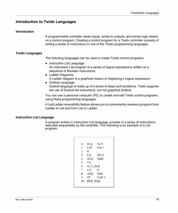
Instruction List Language
A program written in Instruction List language consists of a series of instructions executed sequentially by the controller. The following is an example of a List program.
35011386 05/2009 19
TwidoSuite Languages
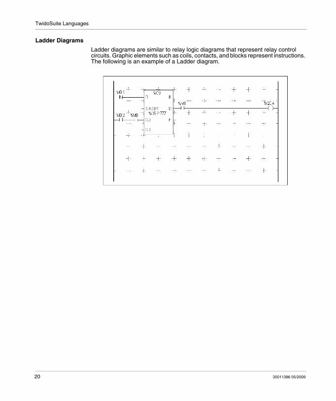
Ladder Diagrams
Ladder diagrams are similar to relay logic diagrams that represent relay control circuits. Graphic elements such as coils, contacts, and blocks represent instructions. The following is an example of a Ladder diagram.
20 35011386 05/2009
TwidoSuite Languages
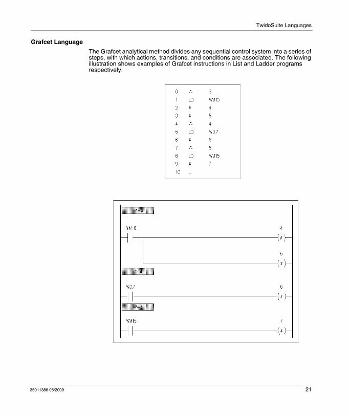
Grafcet Language
The Grafcet analytical method divides any sequential control system into a series of steps, with which actions, transitions, and conditions are associated. The following illustration shows examples of Grafcet instructions in List and Ladder programs respectively.
35011386 05/2009 21

TwidoSuite Languages
22 35011386 05/2009
35011386 05/2009
2
Twido Language Objects
35011386 05/2009
Twido Language Objects
Subject of this Chapter
This chapter provides details about the language objects used for programming Twido controllers.
What's in this Chapter?
This chapter contains the following topics:
Topic Page
Language Object Validation 24
Bit Objects 25
Word Objects 27
Floating Point and Double Word Objects 30
Addressing Bit Objects 34
Addressing Word Objects 35
Addressing Floating Objects 36
Addressing Double Word Objects 37
Addressing Inputs/Outputs 38
Network Addressing 41
Function Block Objects 42
Structured Objects 44
Indexed Objects 48
Symbolizing Objects 50
23
Twido Language Objects
Language Object Validation
Introduction
Word and bit objects are valid if memory space has been allocated in the controller. To do this, they must be used in the application before they are downloaded to the controller.
Example
The range of valid objects is from zero to the maximum reference for that object type. For example, if your application's maximum references for memory words is %MW9, then %MW0 through %MW9 are allocated space. %MW10 in this example is not valid and can not be accessed either internally or externally.
24 35011386 05/2009
Twido Language Objects
Bit Objects
Introduction
Bit objects are bit-type software variables that can be used as operands and tested by Boolean instructions. The following is a list of bit objects:
I/O bitsInternal bits (memory bits) System bitsStep bitsBits extracted from words
List of Operand Bits
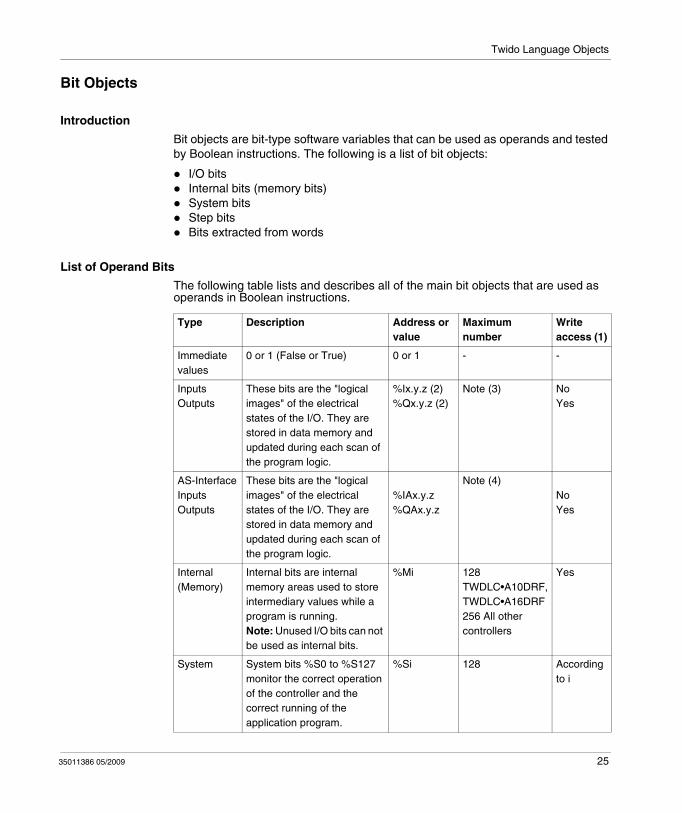
The following table lists and describes all of the main bit objects that are used as operands in Boolean instructions.
Type Description Address or value
Maximum number
Write access (1)
Immediate values
0 or 1 (False or True) 0 or 1 - -
InputsOutputs
These bits are the "logical images" of the electrical states of the I/O. They are stored in data memory and updated during each scan of the program logic.
%Ix.y.z (2)%Qx.y.z (2)
Note (3) NoYes
AS-InterfaceInputsOutputs
These bits are the "logical images" of the electrical states of the I/O. They are stored in data memory and updated during each scan of the program logic.
%IAx.y.z%QAx.y.z
Note (4)NoYes
Internal (Memory)
Internal bits are internal memory areas used to store intermediary values while a program is running. Note: Unused I/O bits can not be used as internal bits.
%Mi 128 TWDLC•A10DRF, TWDLC•A16DRF256 All other controllers
Yes
System System bits %S0 to %S127 monitor the correct operation of the controller and the correct running of the application program.
%Si 128 According to i
35011386 05/2009 25
Twido Language Objects
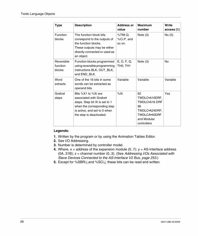
Legends:
1. Written by the program or by using the Animation Tables Editor.2. See I/O Addressing.3. Number is determined by controller model.4. Where, x = address of the expansion module (0..7); y = AS-Interface address
(0A..31B); z = channel number (0..3). (See Addressing I/Os Associated with Slave Devices Connected to the AS-Interface V2 Bus, page 253.)
5. Except for %SBRi.j and %SCi.j, these bits can be read and written.
Function blocks
The function block bits correspond to the outputs of the function blocks. These outputs may be either directly connected or used as an object.
%TMi.Q, %Ci.P, and so on.
Note (3) No (5)
Reversible function blocks
Function blocks programmed using reversible programming instructions BLK, OUT_BLK, and END_BLK.
E, D, F, Q, TH0, TH1
Note (3) No
Word extracts
One of the 16 bits in some words can be extracted as operand bits.
Variable Variable Variable
Grafcet steps
Bits %X1 to %Xi are associated with Grafcet steps. Step bit Xi is set to 1 when the corresponding step is active, and set to 0 when the step is deactivated.
%Xi 62 TWDLC•A10DRF, TWDLC•A16 DRF96 TWDLC•A24DRF, TWDLCA•40DRF and Modular controllers
Yes
Type Description Address or value
Maximum number
Write access (1)
26 35011386 05/2009
Twido Language Objects
Word Objects
Introduction
Word objects that are addressed in the form of 16-bit words that are stored in data memory and can contain an integer value between -32768 and 32767 (except for the fast counter function block which is between 0 and 65535).
Examples of word objects:
Immediate valuesInternal words (%MWi) (memory words)Constant words (%KWi)I/O exchange words (%IWi, %QWi%)AS-Interface analog I/O words (IWAi, %QWAi)System words (%SWi)Function blocks (configuration and/or runtime data)
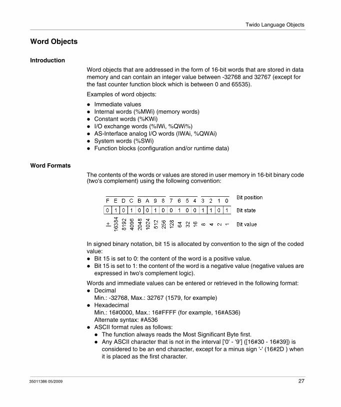
Word Formats
The contents of the words or values are stored in user memory in 16-bit binary code (two's complement) using the following convention:
In signed binary notation, bit 15 is allocated by convention to the sign of the coded value:
Bit 15 is set to 0: the content of the word is a positive value.Bit 15 is set to 1: the content of the word is a negative value (negative values are expressed in two's complement logic).
Words and immediate values can be entered or retrieved in the following format:DecimalMin.: -32768, Max.: 32767 (1579, for example)HexadecimalMin.: 16#0000, Max.: 16#FFFF (for example, 16#A536)Alternate syntax: #A536ASCII format rules as follows:
The function always reads the Most Significant Byte first.Any ASCII character that is not in the interval ['0' - '9'] ([16#30 - 16#39]) is considered to be an end character, except for a minus sign '-' (16#2D ) when it is placed as the first character.
35011386 05/2009 27
Twido Language Objects
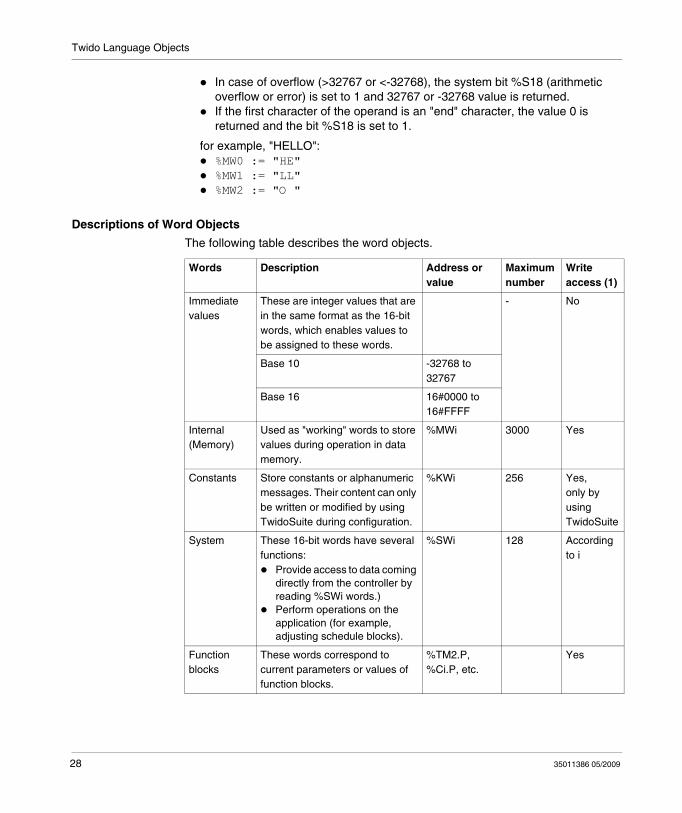
In case of overflow (>32767 or <-32768), the system bit %S18 (arithmetic overflow or error) is set to 1 and 32767 or -32768 value is returned.If the first character of the operand is an "end" character, the value 0 is returned and the bit %S18 is set to 1.
for example, "HELLO":%MW0 := "HE"%MW1 := "LL"%MW2 := "O "
Descriptions of Word Objects
The following table describes the word objects.
Words Description Address or value
Maximum number
Write access (1)
Immediate values
These are integer values that are in the same format as the 16-bit words, which enables values to be assigned to these words.
-
No
Base 10 -32768 to 32767
Base 16 16#0000 to 16#FFFF
Internal (Memory)
Used as "working" words to store values during operation in data memory.
%MWi 3000 Yes
Constants Store constants or alphanumeric messages. Their content can only be written or modified by using TwidoSuite during configuration.
%KWi 256 Yes,only by using TwidoSuite
System These 16-bit words have several functions:
Provide access to data coming directly from the controller by reading %SWi words.)Perform operations on the application (for example, adjusting schedule blocks).
%SWi 128 According to i
Function blocks
These words correspond to current parameters or values of function blocks.
%TM2.P, %Ci.P, etc.
Yes
28 35011386 05/2009
Twido Language Objects
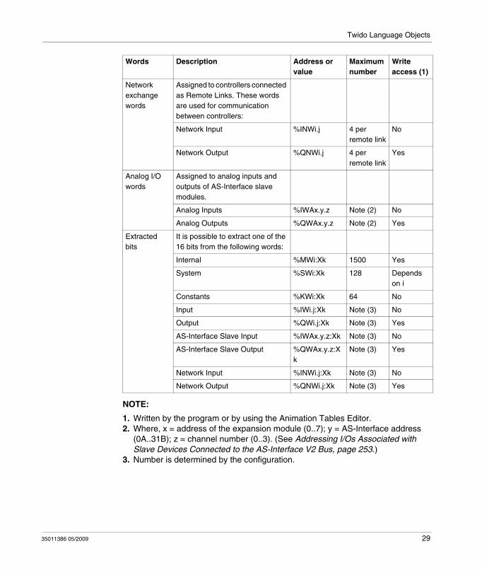
NOTE:
1. Written by the program or by using the Animation Tables Editor.2. Where, x = address of the expansion module (0..7); y = AS-Interface address
(0A..31B); z = channel number (0..3). (See Addressing I/Os Associated with Slave Devices Connected to the AS-Interface V2 Bus, page 253.)
3. Number is determined by the configuration.
Network exchange words
Assigned to controllers connected as Remote Links. These words are used for communication between controllers:
Network Input %INWi.j 4 per remote link
No
Network Output %QNWi.j 4 per remote link
Yes
Analog I/O words
Assigned to analog inputs and outputs of AS-Interface slave modules.
Analog Inputs %IWAx.y.z Note (2) No
Analog Outputs %QWAx.y.z Note (2) Yes
Extracted bits
It is possible to extract one of the 16 bits from the following words:
Internal %MWi:Xk 1500 Yes
System %SWi:Xk 128 Depends on i
Constants %KWi:Xk 64 No
Input %IWi.j:Xk Note (3) No
Output %QWi.j:Xk Note (3) Yes
AS-Interface Slave Input %IWAx.y.z:Xk Note (3) No
AS-Interface Slave Output %QWAx.y.z:Xk
Note (3) Yes
Network Input %INWi.j:Xk Note (3) No
Network Output %QNWi.j:Xk Note (3) Yes
Words Description Address or value
Maximum number
Write access (1)
35011386 05/2009 29
Twido Language Objects
Floating Point and Double Word Objects
Introduction
TwidoSuite allows you to perform operations on floating point and double integer word objects.
A floating point is a mathematical argument which has a decimal in its expression (examples: 3.4E+38, 2.3 or 1.0).
A double integer word consists of 4 bytes stored in data memory and containing a value between -2147483648 and +2147483647.
Floating Point Format and Value
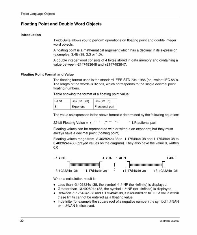
The floating format used is the standard IEEE STD 734-1985 (equivalent IEC 559). The length of the words is 32 bits, which corresponds to the single decimal point floating numbers.
Table showing the format of a floating point value:
The value as expressed in the above format is determined by the following equation:
32-bit Floating Value = * * 1.Fractional part
Floating values can be represented with or without an exponent; but they must always have a decimal point (floating point).
Floating values range from -3.402824e+38 to -1.175494e-38 and 1.175494e-38 to 3.402824e+38 (grayed values on the diagram). They also have the value 0, written 0.0
.
When a calculation result is:
Less than -3.402824e+38, the symbol -1.#INF (for -infinite) is displayed,Greater than +3.402824e+38, the symbol 1.#INF (for +infinite) is displayed,Between -1.175494e-38 and 1.175494e-38, it is rounded off to 0.0. A value within these limits cannot be entered as a floating value.Indefinite (for example the square root of a negative number) the symbol 1.#NAN or -1.#NAN is displayed.
Bit 31 Bits {30...23} Bits {22...0}
S Exponent Fractional part
30 35011386 05/2009
Twido Language Objects
Representation precision is 2-24. To display floating point numbers, it is unnecessary to display more than 6 digits after the decimal point.
NOTE:
the value "1285" is interpreted as a whole value; in order for it to be recognized as a floating point value, it must be written thus: "1285.0"
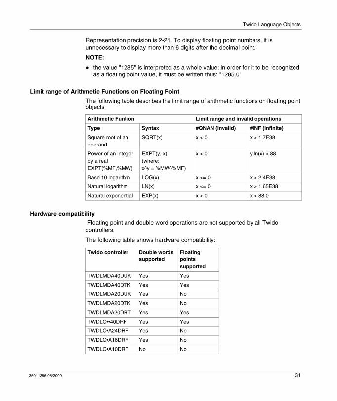
Limit range of Arithmetic Functions on Floating Point
The following table describes the limit range of arithmetic functions on floating point objects
Hardware compatibility
Floating point and double word operations are not supported by all Twido controllers.
The following table shows hardware compatibility:
Arithmetic Funtion Limit range and invalid operations
Type Syntax #QNAN (Invalid) #INF (Infinite)
Square root of an operand
SQRT(x) x < 0 x > 1.7E38
Power of an integer by a realEXPT(%MF,%MW)
EXPT(y, x)(where: x^y = %MW^%MF)
x < 0 y.ln(x) > 88
Base 10 logarithm LOG(x) x <= 0 x > 2.4E38
Natural logarithm LN(x) x <= 0 x > 1.65E38
Natural exponential EXP(x) x < 0 x > 88.0
Twido controller Double words supported
Floating points supported
TWDLMDA40DUK Yes Yes
TWDLMDA40DTK Yes Yes
TWDLMDA20DUK Yes No
TWDLMDA20DTK Yes No
TWDLMDA20DRT Yes Yes
TWDLC••40DRF Yes Yes
TWDLC•A24DRF Yes No
TWDLC•A16DRF Yes No
TWDLC•A10DRF No No
35011386 05/2009 31
Twido Language Objects
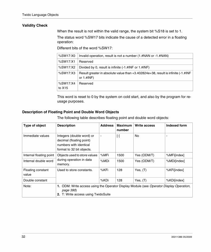
Validity Check
When the result is not within the valid range, the system bit %S18 is set to 1.
The status word %SW17 bits indicate the cause of a detected error in a floating operation:
Different bits of the word %SW17:
This word is reset to 0 by the system on cold start, and also by the program for re-usage purposes.
Description of Floating Point and Double Word Objects
The following table describes floating point and double word objects:
%SW17:X0 Invalid operation, result is not a number (1.#NAN or -1.#NAN)
%SW17:X1 Reserved
%SW17:X2 Divided by 0, result is infinite (-1.#INF or 1.#INF)
%SW17:X3 Result greater in absolute value than +3.402824e+38, result is infinite (-1.#INF or 1.#INF)
%SW17:X4 to X15
Reserved
Type of object Description Address Maximum number
Write access Indexed form
Immediate values Integers (double word) or decimal (floating point) numbers with identical format to 32 bit objects.
- [-] No -
Internal floating point Objects used to store values during operation in data memory.
%MFi 1500 Yes (ODM/T) %MFi[index]
Internal double word %MDi 1500 Yes (ODM/T) %MDi[index]
Floating constant value
Used to store constants. %KFi 128 Yes, (T) %KFi[index]
Double constant %KDi 128 Yes, (T) %KDi[index]
Note: 1. ODM: Write access using the Operator Display Module (see Operator Display Operation, page 390)
2. T: Write access using TwidoSuite
32 35011386 05/2009
Twido Language Objects
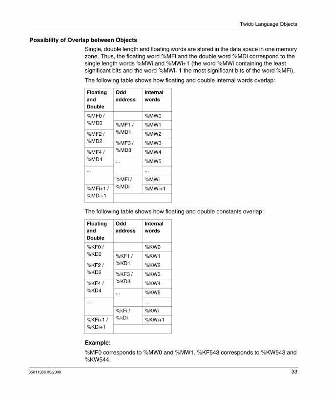
Possibility of Overlap between Objects
Single, double length and floating words are stored in the data space in one memory zone. Thus, the floating word %MFi and the double word %MDi correspond to the single length words %MWi and %MWi+1 (the word %MWi containing the least significant bits and the word %MWi+1 the most significant bits of the word %MFi).
The following table shows how floating and double internal words overlap:
The following table shows how floating and double constants overlap:
Example:
%MF0 corresponds to %MW0 and %MW1. %KF543 corresponds to %KW543 and %KW544.
Floating and Double
Odd address
Internal words
%MF0 / %MD0
%MW0
%MF1 / %MD1
%MW1
%MF2 / %MD2
%MW2
%MF3 / %MD3
%MW3
%MF4 / %MD4
%MW4
... %MW5
... ...
%MFi / %MDi
%MWi
%MFi+1 / %MDi+1
%MWi+1
Floating and Double
Odd address
Internal words
%KF0 / %KD0
%KW0
%KF1 / %KD1
%KW1
%KF2 / %KD2
%KW2
%KF3 / %KD3
%KW3
%KF4 / %KD4
%KW4
... %KW5
... ...
%kFi / %kDi
%KWi
%KFi+1 / %KDi+1
%KWi+1
35011386 05/2009 33
Twido Language Objects
Addressing Bit Objects
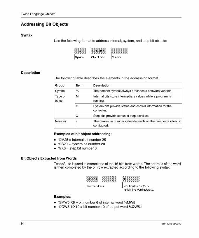
Syntax
Use the following format to address internal, system, and step bit objects:
Description
The following table describes the elements in the addressing format.
Examples of bit object addressing:
%M25 = internal bit number 25%S20 = system bit number 20%X6 = step bit number 6
Bit Objects Extracted from Words
TwidoSuite is used to extract one of the 16 bits from words. The address of the word is then completed by the bit row extracted according to the following syntax:
Examples:
%MW5:X6 = bit number 6 of internal word %MW5%QW5.1:X10 = bit number 10 of output word %QW5.1
Group Item Description
Symbol % The percent symbol always precedes a software variable.
Type of object
M Internal bits store intermediary values while a program is running.
S System bits provide status and control information for the controller.
X Step bits provide status of step activities.
Number i The maximum number value depends on the number of objects configured.
34 35011386 05/2009
Twido Language Objects
Addressing Word Objects
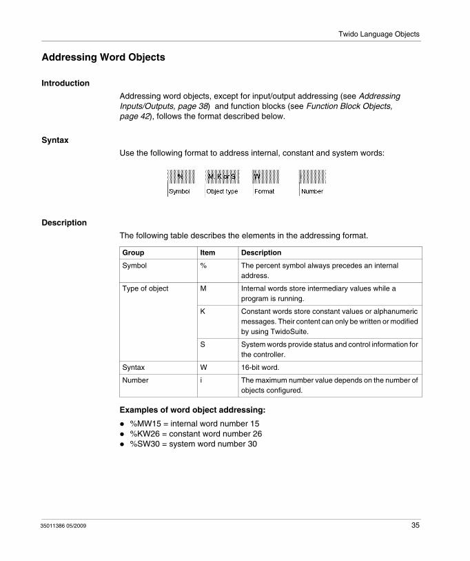
Introduction
Addressing word objects, except for input/output addressing (see Addressing Inputs/Outputs, page 38) and function blocks (see Function Block Objects, page 42), follows the format described below.
Syntax
Use the following format to address internal, constant and system words:
Description
The following table describes the elements in the addressing format.
Examples of word object addressing:
%MW15 = internal word number 15%KW26 = constant word number 26%SW30 = system word number 30
Group Item Description
Symbol % The percent symbol always precedes an internal address.
Type of object M Internal words store intermediary values while a program is running.
K Constant words store constant values or alphanumeric messages. Their content can only be written or modified by using TwidoSuite.
S System words provide status and control information for the controller.
Syntax W 16-bit word.
Number i The maximum number value depends on the number of objects configured.
35011386 05/2009 35
Twido Language Objects
Addressing Floating Objects
Introduction
Addressing floating objects, except for input/output addressing (see Addressing Inputs/Outputs, page 38) and function blocks (see Function Block Objects, page 42), follows the format described below.
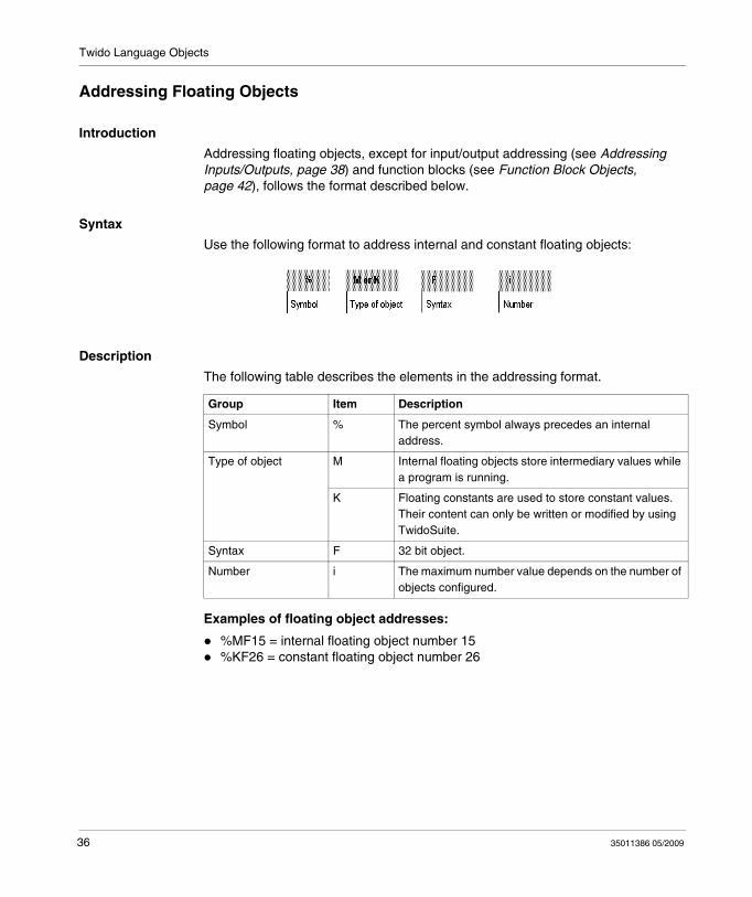
Syntax
Use the following format to address internal and constant floating objects:
Description
The following table describes the elements in the addressing format.
Examples of floating object addresses:
%MF15 = internal floating object number 15%KF26 = constant floating object number 26
Group Item Description
Symbol % The percent symbol always precedes an internal address.
Type of object M Internal floating objects store intermediary values while a program is running.
K Floating constants are used to store constant values. Their content can only be written or modified by using TwidoSuite.
Syntax F 32 bit object.
Number i The maximum number value depends on the number of objects configured.
36 35011386 05/2009
Twido Language Objects
Addressing Double Word Objects
Introduction
Addressing double word objects, except for input/output addressing (see Addressing Inputs/Outputs, page 38) and function blocks (see Function Block Objects, page 42), follows the format described below.
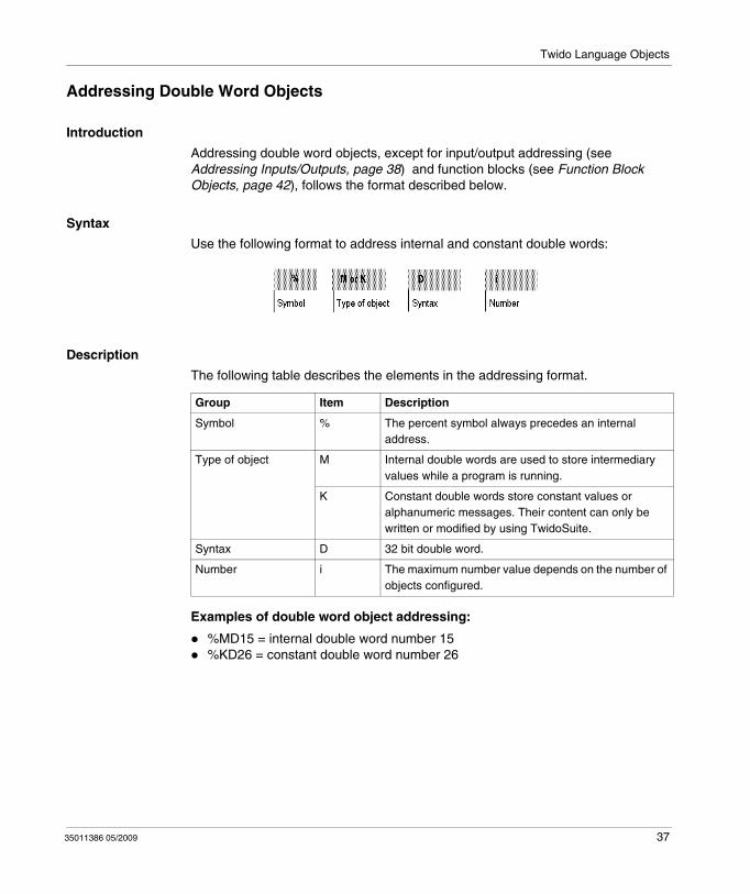
Syntax
Use the following format to address internal and constant double words:
Description
The following table describes the elements in the addressing format.
Examples of double word object addressing:
%MD15 = internal double word number 15%KD26 = constant double word number 26
Group Item Description
Symbol % The percent symbol always precedes an internal address.
Type of object M Internal double words are used to store intermediary values while a program is running.
K Constant double words store constant values or alphanumeric messages. Their content can only be written or modified by using TwidoSuite.
Syntax D 32 bit double word.
Number i The maximum number value depends on the number of objects configured.
35011386 05/2009 37
Twido Language Objects
Addressing Inputs/Outputs
Introduction
Each input/output (I/O) point in a Twido configuration has a unique address: For example, the address "%I0.0.4" is assigned to input 4 of a controller.
I/O addresses can be assigned for the following hardware:
Controller configured as Remote Link MasterController configured as Remote I/O Expansion I/O modules
The TWDNOI10M3 AS-Interface bus interface module and the TWDNCO1M CANopen fieldbus module each uses its own special address system for addressing the I/Os of slave devices connected to its bus:
For TWDNOI10M3, see Addressing I/Os Associated with Slave Devices Connected to the AS-Interface V2 Bus, page 253.For TWDNCO1M, see Addressing PDOs of the CANopen master, page 308.
Multiple References to an Output or Coil
In a program, you can have multiple references to a single output or coil. Only the result of the last one solved is updated on the hardware outputs. For example, %Q0.0.0 can be used more than once in a program, and there will not be an alert for multiple occurrences. So it is important to confirm that the equation will give the required status of the output.
CAUTIONUNINTENDED OPERATION
Review the use of the outputs or coils before making changes to them in your application. There is no duplicate output checking or status indications provided.
Failure to follow these instructions can result in injury or equipment damage.
38 35011386 05/2009
Twido Language Objects
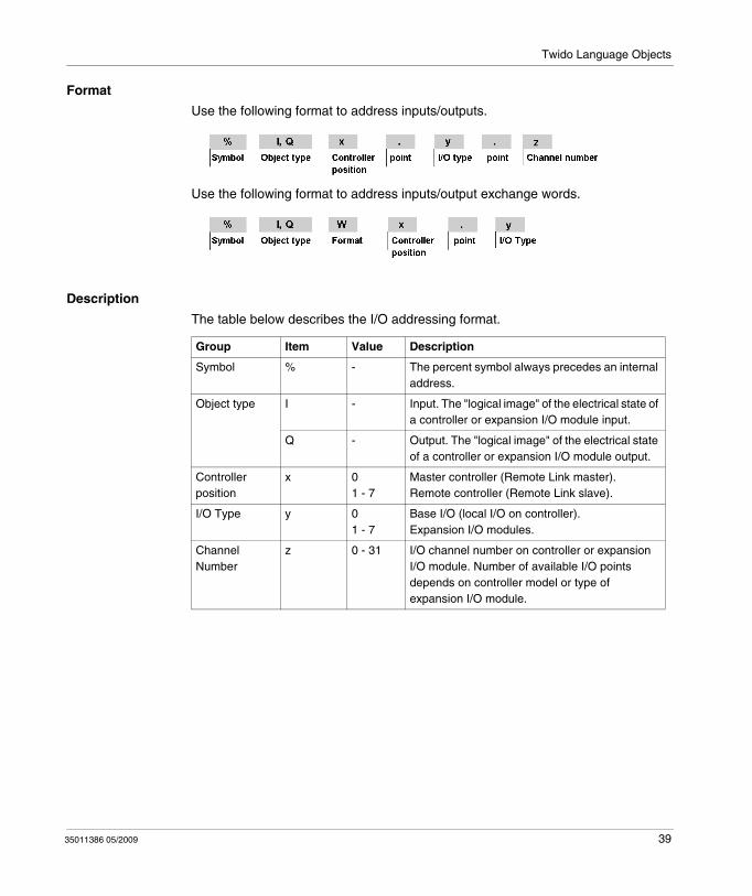
Format
Use the following format to address inputs/outputs.
Use the following format to address inputs/output exchange words.
Description
The table below describes the I/O addressing format.
Group Item Value Description
Symbol % - The percent symbol always precedes an internal address.
Object type I - Input. The "logical image" of the electrical state of a controller or expansion I/O module input.
Q - Output. The "logical image" of the electrical state of a controller or expansion I/O module output.
Controller position
x 01 - 7
Master controller (Remote Link master).Remote controller (Remote Link slave).
I/O Type y 01 - 7
Base I/O (local I/O on controller).Expansion I/O modules.
Channel Number
z 0 - 31 I/O channel number on controller or expansion I/O module. Number of available I/O points depends on controller model or type of expansion I/O module.
35011386 05/2009 39
Twido Language Objects
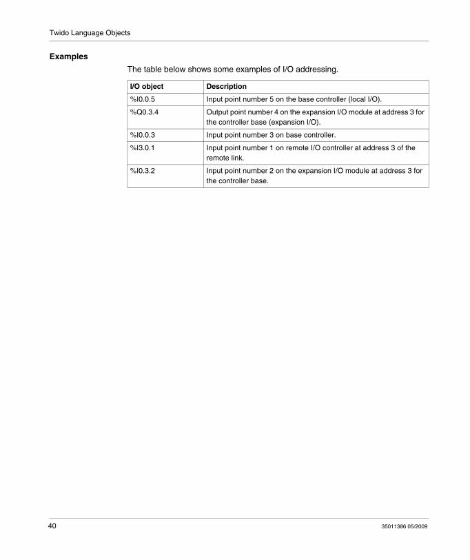
Examples
The table below shows some examples of I/O addressing.
I/O object Description
%I0.0.5 Input point number 5 on the base controller (local I/O).
%Q0.3.4 Output point number 4 on the expansion I/O module at address 3 for the controller base (expansion I/O).
%I0.0.3 Input point number 3 on base controller.
%I3.0.1 Input point number 1 on remote I/O controller at address 3 of the remote link.
%I0.3.2 Input point number 2 on the expansion I/O module at address 3 for the controller base.
40 35011386 05/2009
Twido Language Objects
Network Addressing
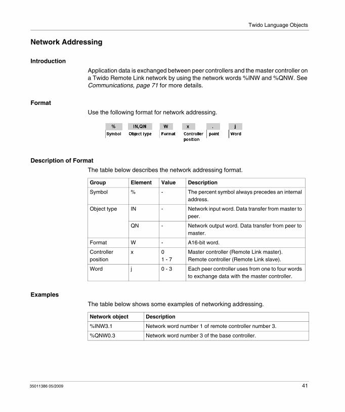
Introduction
Application data is exchanged between peer controllers and the master controller on a Twido Remote Link network by using the network words %INW and %QNW. See Communications, page 71 for more details.
Format
Use the following format for network addressing.
Description of Format
The table below describes the network addressing format.
Examples
The table below shows some examples of networking addressing.
Group Element Value Description
Symbol % - The percent symbol always precedes an internal address.
Object type IN - Network input word. Data transfer from master to peer.
QN - Network output word. Data transfer from peer to master.
Format W - A16-bit word.
Controller position
x 01 - 7
Master controller (Remote Link master).Remote controller (Remote Link slave).
Word j 0 - 3 Each peer controller uses from one to four words to exchange data with the master controller.
Network object Description
%INW3.1 Network word number 1 of remote controller number 3.
%QNW0.3 Network word number 3 of the base controller.
35011386 05/2009 41
Twido Language Objects
Function Block Objects
Introduction
Function blocks provide bit objects and specific words that can be accessed by the program.
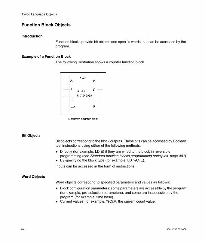
Example of a Function Block
The following illustration shows a counter function block.
Bit Objects
Bit objects correspond to the block outputs. These bits can be accessed by Boolean test instructions using either of the following methods:
Directly (for example, LD E) if they are wired to the block in reversible programming (see Standard function blocks programming principles, page 481).By specifying the block type (for example, LD %Ci.E).
Inputs can be accessed in the form of instructions.
Word Objects
Word objects correspond to specified parameters and values as follows:
Block configuration parameters: some parameters are accessible by the program (for example, pre-selection parameters), and some are inaccessible by the program (for example, time base).Current values: for example, %Ci.V, the current count value.
42 35011386 05/2009

Twido Language Objects
Double word Objects
Double word objects increase the computational capability of your Twido controller while executing system functions, such as fast counters (%FC), very fast counters (%VFC) and pulse generators (%PLS).
Addressing of 32-bit double word objects used with function blocks simply consists in appending the original syntax of the standard word objects with the "D" character. The following example, shows how to address the current value of a fast counter in standard format and in double word format:
%FCi.V is current value of the fast counter in standard format.%FCi.VD is the current value of the fast counter in double word format.
NOTE: Double word objects are not supported by all Twido controllers. Refer to Hardware compatibility, page 31 to find out if your Twido controller can accommodate double words.
Objects Accessible by the Program
See the following appropriate sections for a list of objects that are accessible by the program.
For Basic Function Blocks, see Basic Function Blocks, page 479.For Advanced Function Blocks, see Bit and Word Objects Associated with Advanced Function Blocks, page 532.
35011386 05/2009 43
Twido Language Objects
Structured Objects
Introduction
Structured objects are combinations of adjacent objects. Twido supports the following types of structured objects:
Bit StringsTables of wordsTables of double wordsTables of floating words
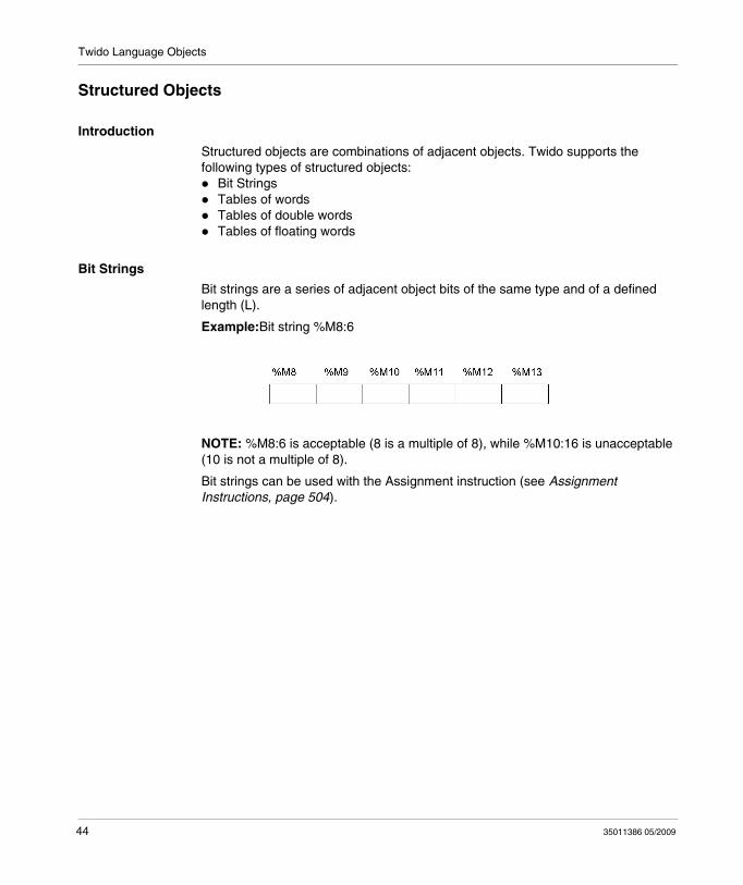
Bit Strings
Bit strings are a series of adjacent object bits of the same type and of a defined length (L).
Example:Bit string %M8:6
NOTE: %M8:6 is acceptable (8 is a multiple of 8), while %M10:16 is unacceptable (10 is not a multiple of 8).
Bit strings can be used with the Assignment instruction (see Assignment Instructions, page 504).
44 35011386 05/2009
Twido Language Objects
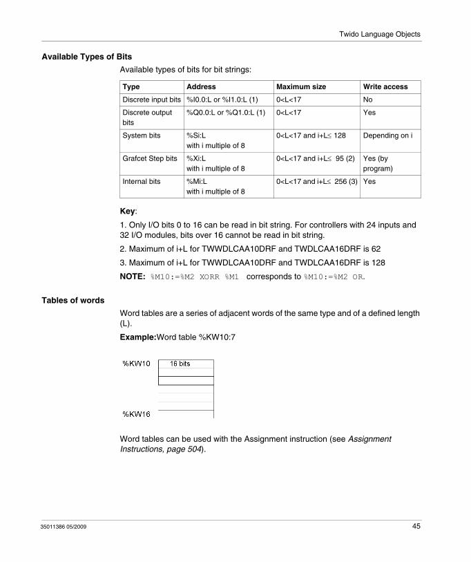
Available Types of Bits
Available types of bits for bit strings:
Key:
1. Only I/O bits 0 to 16 can be read in bit string. For controllers with 24 inputs and 32 I/O modules, bits over 16 cannot be read in bit string.
2. Maximum of i+L for TWWDLCAA10DRF and TWDLCAA16DRF is 62
3. Maximum of i+L for TWWDLCAA10DRF and TWDLCAA16DRF is 128
NOTE: %M10:=%M2 XORR %M1 corresponds to %M10:=%M2 OR.
Tables of words
Word tables are a series of adjacent words of the same type and of a defined length (L).
Example:Word table %KW10:7
Word tables can be used with the Assignment instruction (see Assignment Instructions, page 504).
Type Address Maximum size Write access
Discrete input bits %I0.0:L or %I1.0:L (1) 0<L<17 No
Discrete output bits
%Q0.0:L or %Q1.0:L (1) 0<L<17 Yes
System bits %Si:Lwith i multiple of 8
0<L<17 and i+L≤ 128 Depending on i
Grafcet Step bits %Xi:Lwith i multiple of 8
0<L<17 and i+L≤ 95 (2) Yes (by program)
Internal bits %Mi:Lwith i multiple of 8
0<L<17 and i+L≤ 256 (3) Yes
35011386 05/2009 45
Twido Language Objects
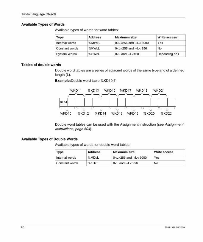
Available Types of Words
Available types of words for word tables:
Tables of double words
Double word tables are a series of adjacent words of the same type and of a defined length (L).
Example:Double word table %KD10:7
Double word tables can be used with the Assignment instruction (see Assignment Instructions, page 504).
Available Types of Double Words
Available types of words for double word tables:
Type Address Maximum size Write access
Internal words %MWi:L 0<L<256 and i+L< 3000 Yes
Constant words %KWi:L 0<L<256 and i+L< 256 No
System Words %SWi:L 0<L and i+L<128 Depending on i
Type Address Maximum size Write access
Internal words %MDi:L 0<L<256 and i+L< 3000 Yes
Constant words %KDi:L 0<L and i+L< 256 No
46 35011386 05/2009
Twido Language Objects
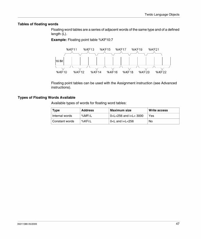
Tables of floating words
Floating word tables are a series of adjacent words of the same type and of a defined length (L).
Example: Floating point table %KF10:7
Floating point tables can be used with the Assignment instruction (see Advanced instructions).
Types of Floating Words Available
Available types of words for floating word tables:
Type Address Maximum size Write access
Internal words %MFi:L 0<L<256 and i+L< 3000 Yes
Constant words %KFi:L 0<L and i+L<256 No
35011386 05/2009 47
Twido Language Objects
Indexed Objects
Introduction
An indexed word is a single or double word or floating point with an indexed object address. There are two types of object addressing:
Direct addressingIndexed addressing
Direct Addressing
A direct address of an object is set and defined when a program is written.
Example: %M26 is an internal bit with the direct address 26.
Indexed Addressing
An indexed address of an object provides a method of modifying the address of an object by adding an index to the direct address of an object. The content of the index is added to the object’s direct address. The index is defined by an internal word %MWi. The number of "index words" is unlimited.
Example: %MW108[%MW2] is a word with an address consisting of the direct address 108 plus the contents of word %MW2.
If word %MW2 has a value of 12, writing to %MW108[%MW2] is equivalent to writing to %MW120 (108 plus 12).
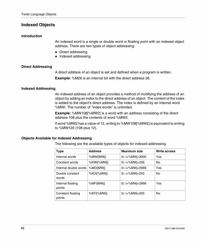
Objects Available for Indexed Addressing
The following are the available types of objects for indexed addressing.
Type Address Maximum size Write access
Internal words %MWi[MWj] 0≤ i+%MWj<3000 Yes
Constant words %KWi[%MWj] 0≤ i+%MWj<256 No
Internal double words %MDi[MWj] 0≤ i+%MWj<2999 Yes
Double constant words
%KDi[%MWj] 0≤ i+%MWj<255 No
Internal floating points
%MFi[MWj] 0≤ i+%MWj<2999 Yes
Constant floating points
%KFi[%MWj] 0≤ i+%MWj<255 No
48 35011386 05/2009
Twido Language Objects
Indexed objects can be used with the assignment instructions (see Assignment Instructions, page 504 for single and double words) and in comparison instructions (see Comparison Instructions, page 509 for single and double words). This type of addressing enables series of objects of the same type (such as internal words and constants) to be scanned in succession, by modifying the content of the index object via the program.
Index Overflow System Bit %S20
An overflow of the index occurs when the address of an indexed object exceeds the limits of the memory zone containing the same type of object. In summary:
The object address plus the content of the index is less than 0.The object address plus the content of the index is greater than the largest word directly referenced in the application. The maximum number is 2999 (for words %MWi) or 255 (for words %KWi).
In the event of an index overflow, the system sets system bit %S20 to 1 and the object is assigned an index value of 0.
NOTE: The user is responsible for monitoring any overflow. Bit %S20 must be read by the user program for possible processing. The user must confirm that it is reset to 0.
%S20 (initial status = 0):On index overflow: set to 1 by the system.Acknowledgment of overflow: set to 0 by the user, after modifying the index.
35011386 05/2009 49
Twido Language Objects
Symbolizing Objects
Introduction
You can use Symbols to address TwidoSuite language objects by name or customized mnemonics. Using symbols allows for quick examination and analysis of program logic, and greatly simplifies the development and testing of an application.
Example
For example, WASH_END is a symbol that could be used to identify a timer function block that represents the end of a wash cycle. Recalling the purpose of this name should be easier than trying to remember the role of a program address such as %TM3.
Guidelines for Defining Symbols
The following are guidelines for defining symbols:
A maximum of 32 characters.Letters (A-Z), numbers (0 -9), or underscores (_).First character must be an alphabetical or accented character. You can not use the percentile sign (%).Do not use spaces or special characters.Not case-sensitive. For example, Pump1 and PUMP1 are the same symbol and can only be used once in an application.
Editing Symbols
Symbols are defined and associated with language objects in the Symbol Editor. Symbols and their comments are stored with the application on the PC hard drive, but are not stored on the controller. Therefore, they can not be transferred with the application to the controller.
50 35011386 05/2009
35011386 05/2009
3
User Memory
35011386 05/2009
User Memory
Subject of this Chapter
This chapter describes the structure and usage of Twido user memory.
What's in this Chapter?
This chapter contains the following topics:
Topic Page
User Memory Structure 52
Backup and Restore without Backup Cartridge or Extended Memory 55
Backup and Restore with a 32K Backup Cartridge 57
Using the 64K Extended Memory Cartridge 60
51
User Memory
User Memory Structure
Introduction
The controller memory accessible to your application is divided into two distinct sets:
Bit valuesWord values (16-bit signed values) and double word values (32-bit signed values)
Bit Memory
The bit memory is located in the controller's built-in RAM. It contains the map of 128 bit objects.
Word Memory
The word memory (16 bits) supports:
Dynamic words: runtime memory (stored in RAM only).Memory words (%MW) and double words (%MD): dynamic system data and system data.Program: descriptors and executable code for tasks.Configuration data: constant words, initial values, and input/output configuration.
Memory Storage Types
The following are the different types of memory storage for Twido controllers.
Random Access Memory.Internal volatile memory: Contains dynamic words, memory words, program and configuration data.EEPROMAn integrated 32 kB EEPROM that provides internal program and data backup. Protects program from corruption due to battery failure or a power outage lasting longer than 30 days. Contains program and configuration data. Holds a maximum of 512 memory words. Program is not backed up here if a 64 kB extended memory cartridge is being used and Twido has been configured to accept the 64 kB extended memory cartridge. The Twido Extreme TWDLEDCK1 has no extended memory cartridge.
52 35011386 05/2009
User Memory
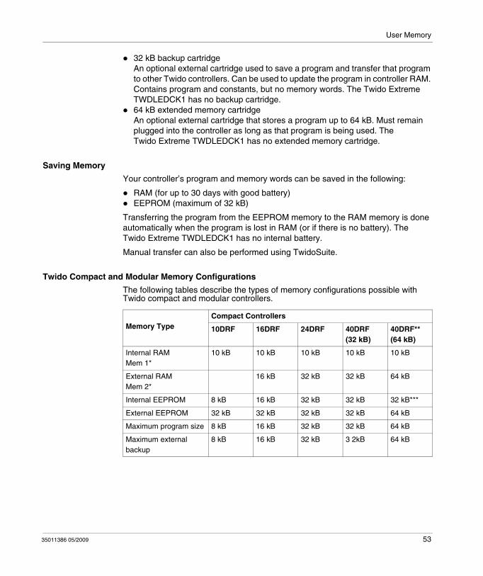
32 kB backup cartridgeAn optional external cartridge used to save a program and transfer that program to other Twido controllers. Can be used to update the program in controller RAM. Contains program and constants, but no memory words. The Twido Extreme TWDLEDCK1 has no backup cartridge.64 kB extended memory cartridgeAn optional external cartridge that stores a program up to 64 kB. Must remain plugged into the controller as long as that program is being used. The Twido Extreme TWDLEDCK1 has no extended memory cartridge.
Saving Memory
Your controller’s program and memory words can be saved in the following:
RAM (for up to 30 days with good battery)EEPROM (maximum of 32 kB)
Transferring the program from the EEPROM memory to the RAM memory is done automatically when the program is lost in RAM (or if there is no battery). The Twido Extreme TWDLEDCK1 has no internal battery.
Manual transfer can also be performed using TwidoSuite.
Twido Compact and Modular Memory Configurations
The following tables describe the types of memory configurations possible with Twido compact and modular controllers.
Memory TypeCompact Controllers
10DRF 16DRF 24DRF 40DRF(32 kB)
40DRF**(64 kB)
Internal RAMMem 1*
10 kB 10 kB 10 kB 10 kB 10 kB
External RAMMem 2*
16 kB 32 kB 32 kB 64 kB
Internal EEPROM 8 kB 16 kB 32 kB 32 kB 32 kB***
External EEPROM 32 kB 32 kB 32 kB 32 kB 64 kB
Maximum program size 8 kB 16 kB 32 kB 32 kB 64 kB
Maximum external backup
8 kB 16 kB 32 kB 3 2kB 64 kB
35011386 05/2009 53
User Memory
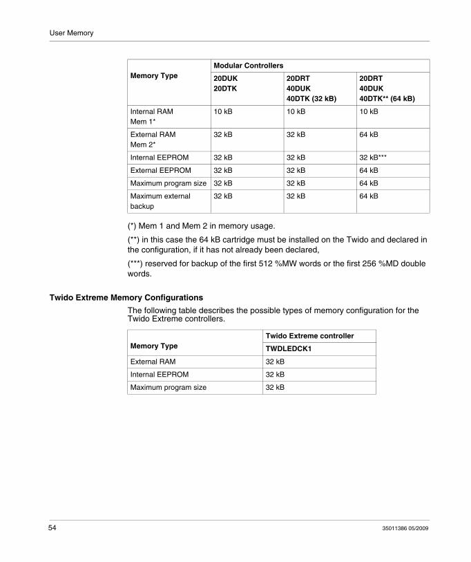
(*) Mem 1 and Mem 2 in memory usage.
(**) in this case the 64 kB cartridge must be installed on the Twido and declared in the configuration, if it has not already been declared,
(***) reserved for backup of the first 512 %MW words or the first 256 %MD double words.
Twido Extreme Memory Configurations
The following table describes the possible types of memory configuration for the Twido Extreme controllers.
Memory TypeModular Controllers
20DUK20DTK
20DRT40DUK40DTK (32 kB)
20DRT40DUK40DTK** (64 kB)
Internal RAMMem 1*
10 kB 10 kB 10 kB
External RAMMem 2*
32 kB 32 kB 64 kB
Internal EEPROM 32 kB 32 kB 32 kB***
External EEPROM 32 kB 32 kB 64 kB
Maximum program size 32 kB 32 kB 64 kB
Maximum external backup
32 kB 32 kB 64 kB
Memory TypeTwido Extreme controller
TWDLEDCK1
External RAM 32 kB
Internal EEPROM 32 kB
Maximum program size 32 kB
54 35011386 05/2009
User Memory
Backup and Restore without Backup Cartridge or Extended Memory
Introduction
The following information details backup and restore memory functions in modular and compact controllers without a backup cartridge or extended memory plugged in.
This section does not apply to the Twido Extreme TWDLEDCK1 PLC which also has no backup cartridge. This is described in Twido Extreme User Memory.
At a Glance
Twido programs, memory words and configuration data can be backed up using the controllers internal EEPROM. Because saving a program to the internal EEPROM clears any previously backed up memory words, the program must be backed up first, then the configured memory words. Dynamic data can be stored in memory words then backed up to the EEPROM. If there is no program saved to the internal EEPROM you cannot save memory words to it.
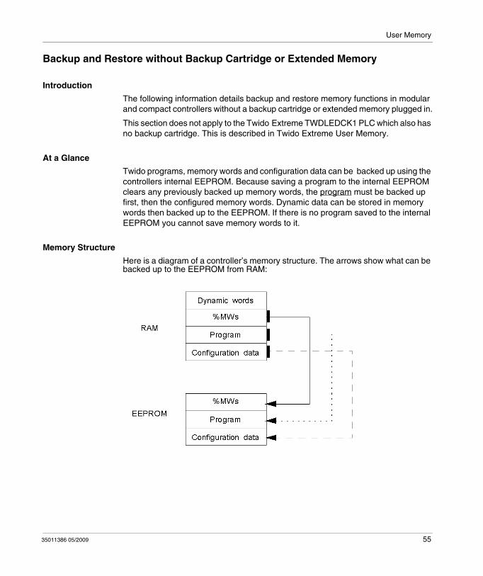
Memory Structure
Here is a diagram of a controller’s memory structure. The arrows show what can be backed up to the EEPROM from RAM:
35011386 05/2009 55
User Memory
Program Backup
Here are the steps for backing up your program into EEPROM.
Program Restore
During power up there is one way the program will be restored to RAM from the EEPROM (assuming there is no cartridge or extended memory in place):
The RAM program is not valid
To restore a program manually from EEPROM do the following:From the TwidoSuite window, select Memory Cartridge Commands from Program → Debug , select a connection and click Restore.
Data (%MWs) Backup
Here are the steps for backing up data (memory words) into the EEPROM:
Data (%MWs) Restore
Restore %MWs manually by setting system bit %S95 to 1.
For this to work the following must be true:A valid backup application is present in the EEPROMThe application in RAM matches the backup application in EEPROMThe backup memory words are valid
Step Action
1 The following must be true:There is a valid program in RAM.
2 From the TwidoSuite window, select See Memory Information from Program → Debug → Check PLC and click Save.Note: Check PLC can only be used in connected mode.
Step Action
1 For this to work the following must be true:A valid program in RAM (%SW96:X6=1).The same valid program already backed up into the EEPROM.Memory words configured in the program.
2 Set %SW97 to the length of the memory words to be saved.Note: Length cannot exceed the configured memory word length, and it must be greater than 0 but not greater than 512.
3 Set %SW96:X0 to 1.
56 35011386 05/2009

User Memory
Backup and Restore with a 32K Backup Cartridge
Introduction
The following information details backup and restore memory functions in modular and compact controllers using a 32K backup cartridge.
This section does not apply to the Twido Extreme TWDLEDCK1 PLC which has no backup cartridge. This is described in Twido Extreme User Memory.
At a Glance
The backup cartridge is used to save a program and transfer that program to other Twido controllers. It should be removed from a controller and set aside once the program has been installed or saved. Only program and configuration data can be saved to the cartridge (%MWs cannot be saved to the 32K backup cartridge). Dynamic data can be stored in memory words then backed up to the EEPROM. When program installation is complete any %MWs that were backed up to the internal EEPROM prior to installation will be lost.
35011386 05/2009 57
User Memory
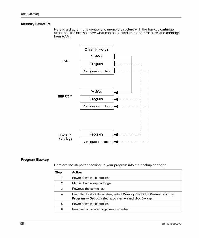
Memory Structure
Here is a diagram of a controller’s memory structure with the backup cartridge attached. The arrows show what can be backed up to the EEPROM and cartridge from RAM:
Program Backup
Here are the steps for backing up your program into the backup cartridge:
Step Action
1 Power down the controller.
2 Plug in the backup cartridge.
3 Powerup the controller.
4 From the TwidoSuite window, select Memory Cartridge Commands from Program → Debug, select a connection and click Backup.
5 Power down the controller.
6 Remove backup cartridge from controller.
58 35011386 05/2009
User Memory
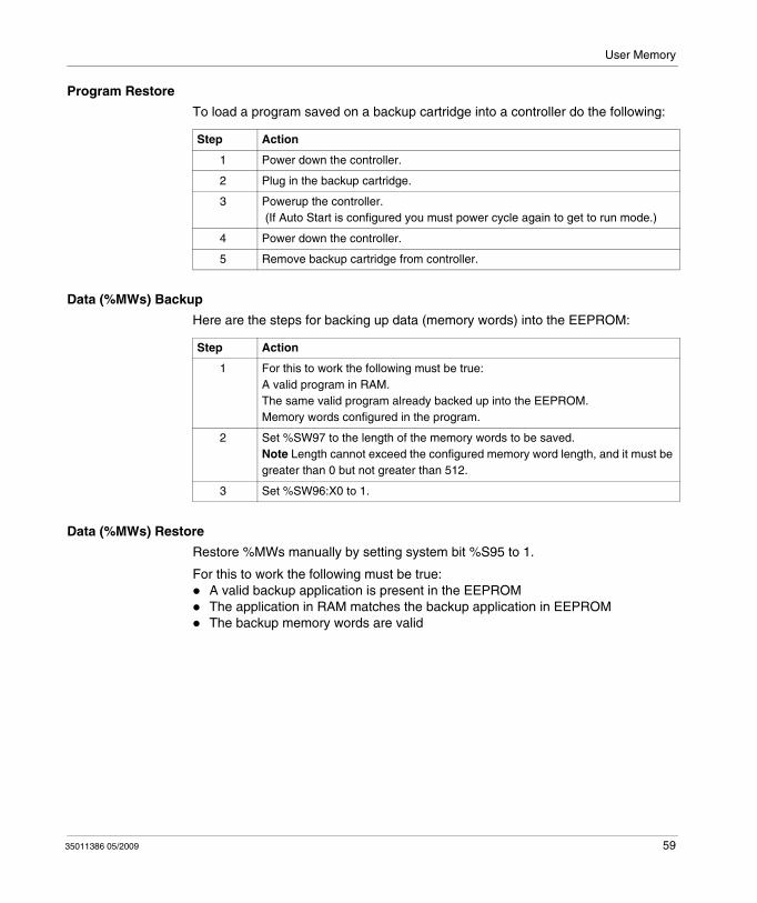
Program Restore
To load a program saved on a backup cartridge into a controller do the following:
Data (%MWs) Backup
Here are the steps for backing up data (memory words) into the EEPROM:
Data (%MWs) Restore
Restore %MWs manually by setting system bit %S95 to 1.
For this to work the following must be true:A valid backup application is present in the EEPROMThe application in RAM matches the backup application in EEPROMThe backup memory words are valid
Step Action
1 Power down the controller.
2 Plug in the backup cartridge.
3 Powerup the controller. (If Auto Start is configured you must power cycle again to get to run mode.)
4 Power down the controller.
5 Remove backup cartridge from controller.
Step Action
1 For this to work the following must be true:A valid program in RAM.The same valid program already backed up into the EEPROM.Memory words configured in the program.
2 Set %SW97 to the length of the memory words to be saved.Note Length cannot exceed the configured memory word length, and it must be greater than 0 but not greater than 512.
3 Set %SW96:X0 to 1.
35011386 05/2009 59

User Memory
Using the 64K Extended Memory Cartridge
Introduction
The following information details using the memory functions in modular controllers using a 64K extended memory cartridge.
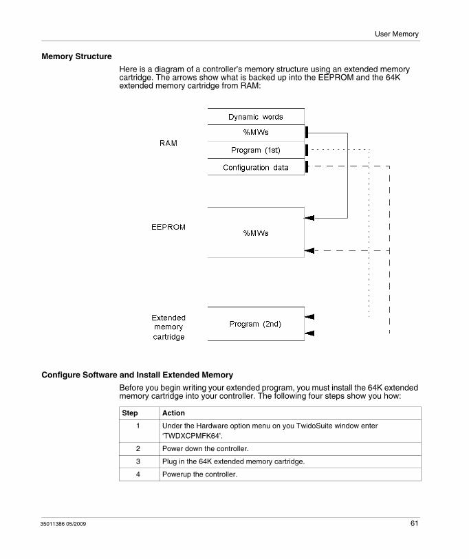
At a Glance
The 64K extended memory cartridge is used to extend the program memory capability of your Twido controller from 32K to 64K. It must remain plugged into the controller as long as the extended program is being used. If the cartridge is removed the controller will enter the stopped state. Memory words are still backed up into the EEPROM in the controller. Dynamic data can be stored in memory words then backed up to the EEPROM. The 64K extended memory cartridge has the same power up behavior as the 32K backup cartridge.
60 35011386 05/2009
User Memory
Memory Structure
Here is a diagram of a controller’s memory structure using an extended memory cartridge. The arrows show what is backed up into the EEPROM and the 64K extended memory cartridge from RAM:
Configure Software and Install Extended Memory
Before you begin writing your extended program, you must install the 64K extended memory cartridge into your controller. The following four steps show you how:
Step Action
1 Under the Hardware option menu on you TwidoSuite window enter ‘TWDXCPMFK64’.
2 Power down the controller.
3 Plug in the 64K extended memory cartridge.
4 Powerup the controller.
35011386 05/2009 61

User Memory
Save your program.
Once your 64K extended memory cartridge has been installed and your program written:
From the TwidoSuite window, select Memory Cartridge Commands from Program → Debug, select a connection and click Backup.
Data (%MWs) Backup
Here are the steps for backing up data (memory words) into the EEPROM:
Data (%MWs) Restore
Restore %MWs manually by setting system bit %S95 to 1.
For this to work the following must be true:A valid program is presentThe backup memory words are valid
Step Action
1 For this to work the following must be true:A valid program is presentMemory words are configured in the program.
2 Set %SW97 to the length of the memory words to be saved.Note: Length cannot exceed the configured memory word length, and it must be greater than 0 but not greater than 512.
3 Set %SW96:X0 to 1.
62 35011386 05/2009

35011386 05/2009
4
Event task management
35011386 05/2009
Event task management
Subject of this Chapter
This chapter describes event tasks and how they are executed in the controller.
NOTE: Event tasks are not managed by the Twido Brick 10 controller (TWDLCAA10DRF).
What's in this Chapter?
This chapter contains the following topics:
Topic Page
Overview of Event Tasks 64
Description of Different Event Sources 65
Event Management 67
63
Event task management
Overview of Event Tasks
Introduction
The previous chapter presented periodic and cyclic tasks in which objects are updated at the start and end of the task. Event sources may cause a certain task to be stopped while higher priority (event) tasks are executed to allow objects to be updated more quickly.
An event task:
is a part of a program executed when a given condition is met (event source),has a higher priority than the main program,produces a rapid response time enabling the overall response time of the system to be reduced.
Description of an Event
An event is composed of:
an event source which can be defined as a software or hardware interrupt condition to interrupt the main program (see page 65), a section which is an independent programmed entity related to an event,an event queue which can be used to store a list of events until they are executed,a priority level which specifies the order of event execution.
64 35011386 05/2009
Event task management
Description of Different Event Sources
Overview of Different Event Sources
An event source needs to be managed by the software to make sure the main program is properly interrupted by the event, and to call the programming section linked to the event. The application scan time has no effect on the execution of the events.
The following 9 event sources are allowed:
4 conditions linked to the VFC function block thresholds (2 events per %VFC instance), 4 conditions linked to the physical inputs of a controller base,1 periodic condition.
An event source can only be attached to a single event, and must be immediately detected by TwidoSuite. Once it is detected, the software executes the programming section attached to the event: each event is attached to a subroutine labeled SRi: defined on configuration of the event sources.
Physical Input Events of a Controller Base
Inputs %I0.2, %I0.3, %I0.4 and %I0.5 can be used as event sources, provided they are not locked and that the events are allowed during configuration.
Event processing can be activated by inputs 2 to 5 of a controller base (position 0), on a rising or falling edge.
For further details on configuring this event, refer to the section entitled "Hardware Configuration -> Input Configuration" in the "TwidoSuite Operation Guide" on-line help.
Output Event of a %VFC Function Block
Outputs TH0 and TH1 of the %VFC function block are event sources. Outputs TH0 and TH1 are respectively set:
to 1 when the value is greater than threshold S0 and threshold S1,to 0 when the value is less than threshold S0 and threshold S1.
A rising or falling edge of these outputs can activate an event process.
For further details on configuring this event, refer to the section entitled "Software Configuration -> Very Fast Counters" in the "TwidoSuite Operation Guide" on-line help.
35011386 05/2009 65

Event task management
Periodic event
This event periodically executes a single programming section. This task has higher priority than the main task (master).
However, this event source has lower priority than the other event sources.
The period of this task is set on configuration, from 5 to 255 ms. Only one periodic event can be used.
For further details on configuring this event, refer to the section entitled "Configuring Program Parameters -> Scan Mode" in the "TwidoSuite Operation Guide" on-line help.
66 35011386 05/2009
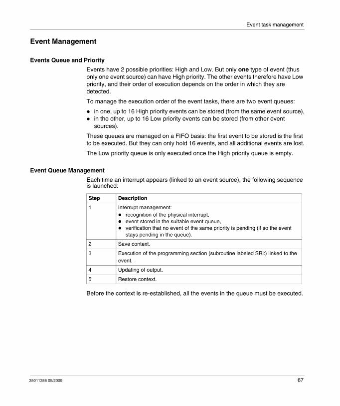
Event task management
Event Management
Events Queue and Priority
Events have 2 possible priorities: High and Low. But only one type of event (thus only one event source) can have High priority. The other events therefore have Low priority, and their order of execution depends on the order in which they are detected.
To manage the execution order of the event tasks, there are two event queues:
in one, up to 16 High priority events can be stored (from the same event source),in the other, up to 16 Low priority events can be stored (from other event sources).
These queues are managed on a FIFO basis: the first event to be stored is the first to be executed. But they can only hold 16 events, and all additional events are lost.
The Low priority queue is only executed once the High priority queue is empty.
Event Queue Management
Each time an interrupt appears (linked to an event source), the following sequence is launched:
Before the context is re-established, all the events in the queue must be executed.
Step Description
1 Interrupt management: recognition of the physical interrupt,event stored in the suitable event queue,verification that no event of the same priority is pending (if so the event stays pending in the queue).
2 Save context.
3 Execution of the programming section (subroutine labeled SRi:) linked to the event.
4 Updating of output.
5 Restore context.
35011386 05/2009 67

Event task management
Event check
System bits and words are used to check the events (see page 718):
%S31: used to execute or delay an event,%S38: used to decide whether or not to place events in the events queue,%S39: used to find out if events are lost,%SW48: shows how many events have been executed since the last cold start (counts all events except periodic events.)
The value of bit %S39 and word %SW48 is reset to zero and that of %S31 and %S38 is set to its initial state 1 on a cold restart or after an application is loaded, but remains unchanged after a warm restart. In all cases, the events queue is reset.
68 35011386 05/2009
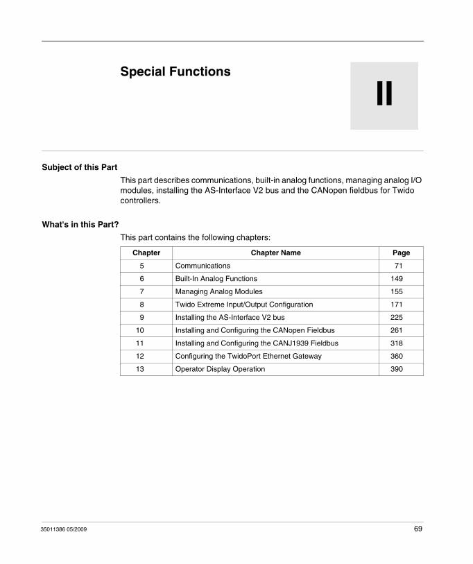
35011386 05/2009
II
Special Functions
35011386 05/2009
Special Functions
Subject of this Part
This part describes communications, built-in analog functions, managing analog I/O modules, installing the AS-Interface V2 bus and the CANopen fieldbus for Twido controllers.
What's in this Part?
This part contains the following chapters:
Chapter Chapter Name Page
5 Communications 71
6 Built-In Analog Functions 149
7 Managing Analog Modules 155
8 Twido Extreme Input/Output Configuration 171
9 Installing the AS-Interface V2 bus 225
10 Installing and Configuring the CANopen Fieldbus 261
11 Installing and Configuring the CANJ1939 Fieldbus 318
12 Configuring the TwidoPort Ethernet Gateway 360
13 Operator Display Operation 390
69

Special Functions
70 35011386 05/2009
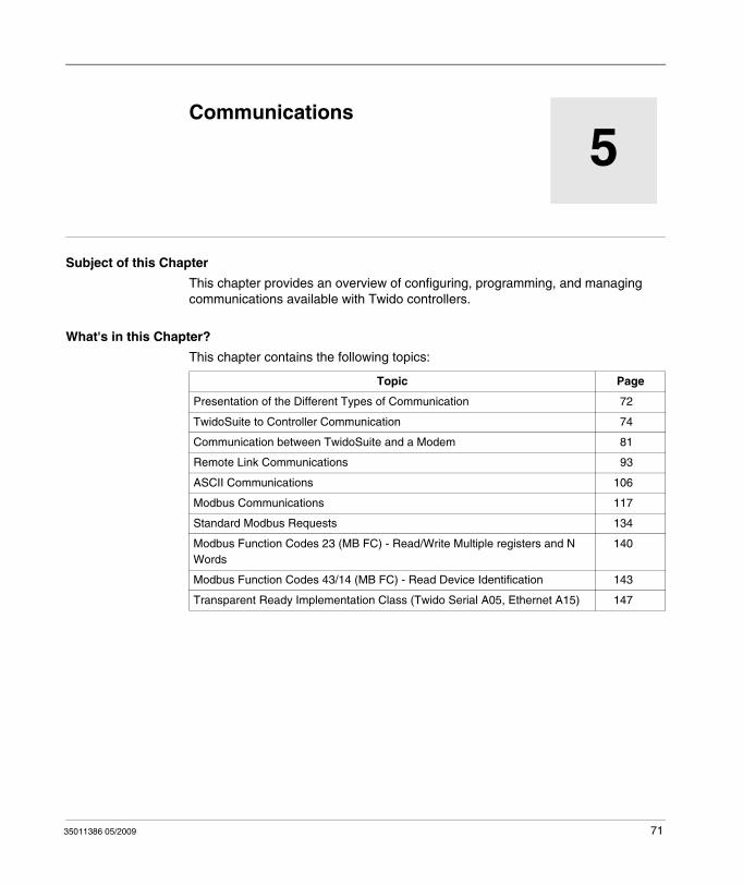
35011386 05/2009
5
Communications
35011386 05/2009
Communications
Subject of this Chapter
This chapter provides an overview of configuring, programming, and managing communications available with Twido controllers.
What's in this Chapter?
This chapter contains the following topics:
Topic Page
Presentation of the Different Types of Communication 72
TwidoSuite to Controller Communication 74
Communication between TwidoSuite and a Modem 81
Remote Link Communications 93
ASCII Communications 106
Modbus Communications 117
Standard Modbus Requests 134
Modbus Function Codes 23 (MB FC) - Read/Write Multiple registers and N Words
140
Modbus Function Codes 43/14 (MB FC) - Read Device Identification 143
Transparent Ready Implementation Class (Twido Serial A05, Ethernet A15) 147
71
Communications
Presentation of the Different Types of Communication
At a Glance
Twido provides one or two serial communications ports used for communications to remote I/O controllers, peer controllers, or general devices. Either port, if available, can be used for any of the services, with the exception of communicating with TwidoSuite, which can only be performed using the first port. Three different base protocols are supported on each Twido controller: Remote Link, ASCII, or Modbus (modbus master or modbus slave).
Moreover, the TWDLC•E40DRF compact controllers provide one RJ45 Ethernet communications port. They support the Modbus TCP/IP client/server protocol for peer-to-peer communications between controllers over the Ethernet network.
The TWDLEDCK1 Twido Extreme controller has only one serial port and supports Modbus, ASCII, Ethernet and BlueTooth communications.
Remote Link
The remote link is a high-speed master/slave bus designed to communicate a small amount of data between the master controller and up to seven remote (slave) controllers. Application or I/O data is transferred, depending on the configuration of the remote controllers. A mixture of remote controller types is possible, where some can be remote I/O and some can be peers.
Remote link is not supported (neither serial RS485 nor CANJ1939) by the TWDLEDCK1 Twido Extreme controller.
ASCII
The ASCII protocol is a simple half-duplex character mode protocol used to transmit and/or receive a character string to/from a simple device (printer or terminal). This protocol is supported only via the "EXCH" instruction.
For the TWDLEDCK1 Twido Extreme controller, if ASCII is used then 0V must be applied to the communication strap contact (pin 22) to enable communication.
Modbus
The Modbus protocol is a master/slave protocol that allows for one, and only one, master to request responses from slaves, or to act based on the request. The master can address individual slaves, or can initiate a broadcast message to all slaves. Slaves return a message (response) to queries that are addressed to them individually. Responses are not returned to broadcast queries from the master.
72 35011386 05/2009
Communications
Modbus master - The modbus master mode allows the Twido controller to send a modbus query to a slave and await its reply. The modbus master mode is supported only via the "EXCH" instruction. Both Modbus ASCII and RTU are supported in modbus master mode.
NOTE: It is possible to send a Modbus request to an IP slave that would not be declared in the IP Slave List.
Modbus Slave - The modbus slave mode allows the Twido controller to respond to modbus queries from a modbus master, and is the default communications mode if no other type of communication is configured. The Twido controller supports the standard modbus data and control functions and service extensions for object access. Both Modbus ASCII and RTU are supported in modbus slave mode. Furthermore, il is possible to change the IP address / IP sub mask and IP gateway through some %SW without modifying the application.
NOTE: 32 devices (without repeaters) can be installed on an RS485 network (1 master and up to 31 slaves), the addresses of which can be between 1 and 247.
Modbus TCP/IP
NOTE: Modbus TCP/IP is solely supported by TWDLC•E40DRF series of compact controllers with built-in Ethernet network interface.
The following information describes the Modbus Application Protocol (MBAP).
The Modbus Application Protocol (MBAP) is a layer-7 protocol providing peer-to-peer communication between programmable logic controllers (PLCs) and other nodes on a LAN.
The current Twido controller TWDLC•E40DRF implementation transports Modbus Application Protocol over TCP/IP on the Ethernet network. Modbus protocol transactions are typical request-response message pairs. A PLC can be either client or server depending on whether it is querying or answering messages.
Ethernet Server / Modbus Slave
The Brick 40 is a part of a network and a supervision system access to the Twido for retrieving some data. This requirement consist in the possibility to change the IP adress / IP sub mask and IP gateway through some %SW without modifying the application.
Ethernet Client / Modbus Master
The Brick 40is a supervision system, requiring some data to other Ethernet equipment (such as OTB or an other Brick 40). Tis requirement consists in the possibility to send a Modbus request to an IP slave that would not be declared in words to retrieve the Ethernet current status.
35011386 05/2009 73
Communications
TwidoSuite to Controller Communication
At a Glance
Each Twido controller has a built-in EIA RS485 terminal port, with its own internal power supply, on Port 1. (The TWDLEDCK1 Twido Extreme controller has only one serial port). Port 1 must be used to communicate with the TwidoSuite programming software.
No optional cartridge or communication module can be used for this port. A modem, however, can be used on this port.
There are several ways to connect the PC to the Twido controller RS485 Port 1:
By TSX PCX cable,By telephone line: Modem connection,By Bluetooth for the TWDLEDCK1 Twido Extreme controller using a Bluetooth adapter (dongle) VW3 A8114.
Moreover, the TWDLC•E40DRF compact controllers have a built-in RJ45 Ethernet network connection port that can be used to communicate with the Ethernet-capable PC running the TwidoSuite programming software.
There are two ways for the Ethernet-capable PC to communicate with a TWDLC•E40DRF Twido controller RJ45 port:
By direct cable connection via a UTP Cat5 RJ45 Ethernet crossover cable (not recommended),By connection to the Ethernet network via a SFTP Cat5 RJ45 Ethernet cable available from the Schneider Electric catalog (cable reference: 490NTW000••).
The TWDLEDCK1 Twido Extreme controller can also be connected to the Ethernet network using a OSITRACK XGS Z33ETH Modbus-Ethernet connection box.
WARNINGUNINTENDED EQUIPMENT OPERATION
Use TwidoSuite to properly disconnect a TSX PCX1031, TSX CRJMD25, or Ethernet communication cable before physically removing a cable from one controller and rapidly reinserting into another, as TwidoSuite may not sense the disconnection if done rapidly.
Failure to follow these instructions can result in death, serious injury, or equipment damage.
74 35011386 05/2009
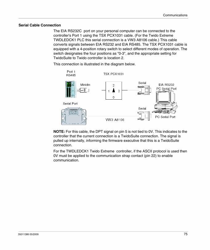
Communications
Serial Cable Connection
The EIA RS232C port on your personal computer can be connected to the controller's Port 1 using the TSX PCX1031 cable. (For the Twido Extreme TWDLEDCK1 PLC this serial connection is a VW3 A8106 cable.) This cable converts signals between EIA RS232 and EIA RS485. The TSX PCX1031 cable is equipped with a 4-position rotary switch to select different modes of operation. The switch designates the four positions as "0-3", and the appropriate setting for TwidoSuite to Twido controller is location 2.
This connection is illustrated in the diagram below.
NOTE: For this cable, the DPT signal on pin 5 is not tied to 0V. This indicates to the controller that the current connection is a TwidoSuite connection. The signal is pulled up internally, informing the firmware executive that this is a TwidoSuite connection.
For the TWDLEDCK1 Twido Extreme controller, if the ASCII protocol is used then 0V must be applied to the communication strap contact (pin 22) to enable communication.
35011386 05/2009 75
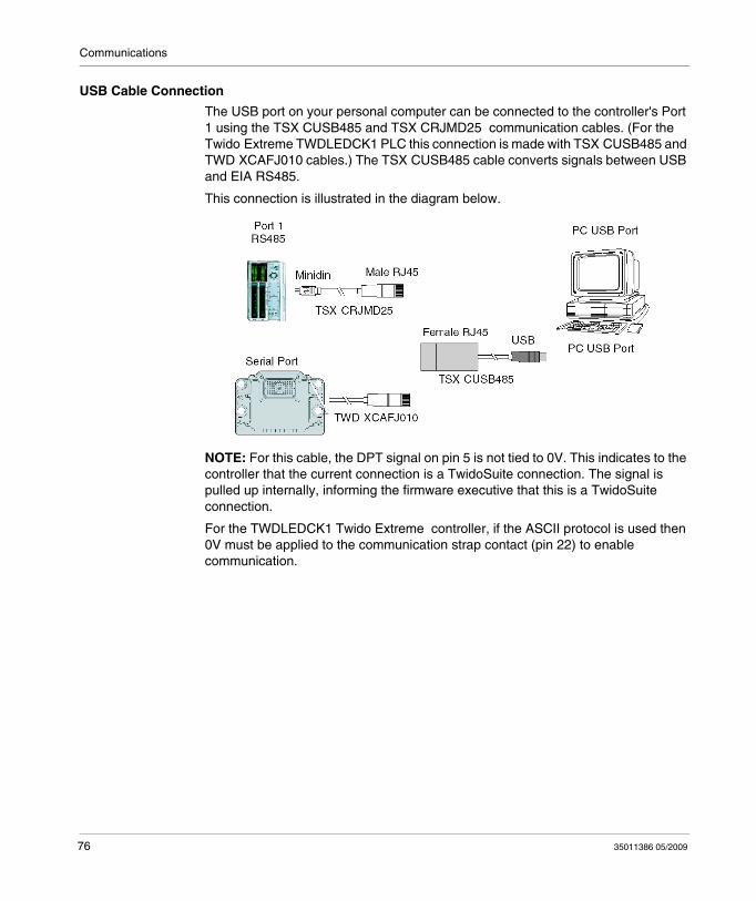
Communications
USB Cable Connection
The USB port on your personal computer can be connected to the controller's Port 1 using the TSX CUSB485 and TSX CRJMD25 communication cables. (For the Twido Extreme TWDLEDCK1 PLC this connection is made with TSX CUSB485 and TWD XCAFJ010 cables.) The TSX CUSB485 cable converts signals between USB and EIA RS485.
This connection is illustrated in the diagram below.
NOTE: For this cable, the DPT signal on pin 5 is not tied to 0V. This indicates to the controller that the current connection is a TwidoSuite connection. The signal is pulled up internally, informing the firmware executive that this is a TwidoSuite connection.
For the TWDLEDCK1 Twido Extreme controller, if the ASCII protocol is used then 0V must be applied to the communication strap contact (pin 22) to enable communication.
76 35011386 05/2009
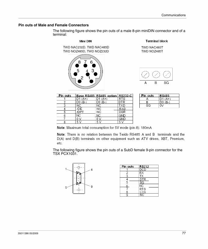
Communications
Pin outs of Male and Female Connectors
The following figure shows the pin outs of a male 8-pin miniDIN connector and of a terminal:
The following figure shows the pin outs of a SubD female 9-pin connector for the TSX PCX1031.
35011386 05/2009 77
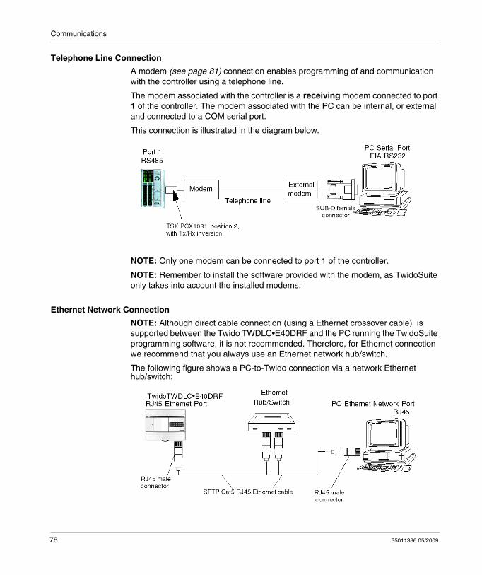
Communications
Telephone Line Connection
A modem (see page 81) connection enables programming of and communication with the controller using a telephone line.
The modem associated with the controller is a receiving modem connected to port 1 of the controller. The modem associated with the PC can be internal, or external and connected to a COM serial port.
This connection is illustrated in the diagram below.
NOTE: Only one modem can be connected to port 1 of the controller.
NOTE: Remember to install the software provided with the modem, as TwidoSuite only takes into account the installed modems.
Ethernet Network Connection
NOTE: Although direct cable connection (using a Ethernet crossover cable) is supported between the Twido TWDLC•E40DRF and the PC running the TwidoSuite programming software, it is not recommended. Therefore, for Ethernet connection we recommend that you always use an Ethernet network hub/switch.
The following figure shows a PC-to-Twido connection via a network Ethernet hub/switch:
78 35011386 05/2009
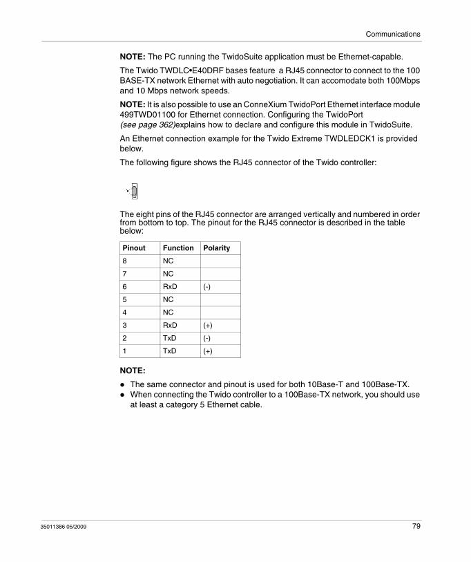
Communications
NOTE: The PC running the TwidoSuite application must be Ethernet-capable.
The Twido TWDLC•E40DRF bases feature a RJ45 connector to connect to the 100 BASE-TX network Ethernet with auto negotiation. It can accomodate both 100Mbps and 10 Mbps network speeds.
NOTE: It is also possible to use an ConneXium TwidoPort Ethernet interface module 499TWD01100 for Ethernet connection. Configuring the TwidoPort (see page 362)explains how to declare and configure this module in TwidoSuite.
An Ethernet connection example for the Twido Extreme TWDLEDCK1 is provided below.
The following figure shows the RJ45 connector of the Twido controller:
The eight pins of the RJ45 connector are arranged vertically and numbered in order from bottom to top. The pinout for the RJ45 connector is described in the table below:
NOTE:
The same connector and pinout is used for both 10Base-T and 100Base-TX. When connecting the Twido controller to a 100Base-TX network, you should use at least a category 5 Ethernet cable.
Pinout Function Polarity
8 NC
7 NC
6 RxD (-)
5 NC
4 NC
3 RxD (+)
2 TxD (-)
1 TxD (+)
35011386 05/2009 79
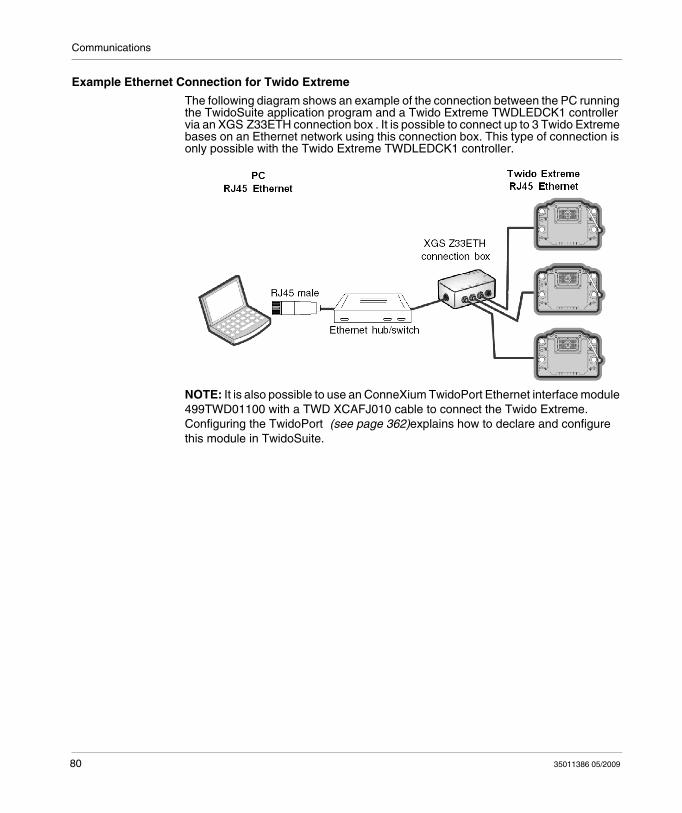
Communications
Example Ethernet Connection for Twido Extreme
The following diagram shows an example of the connection between the PC running the TwidoSuite application program and a Twido Extreme TWDLEDCK1 controller via an XGS Z33ETH connection box . It is possible to connect up to 3 Twido Extreme bases on an Ethernet network using this connection box. This type of connection is only possible with the Twido Extreme TWDLEDCK1 controller.
NOTE: It is also possible to use an ConneXium TwidoPort Ethernet interface module 499TWD01100 with a TWD XCAFJ010 cable to connect the Twido Extreme. Configuring the TwidoPort (see page 362)explains how to declare and configure this module in TwidoSuite.
80 35011386 05/2009
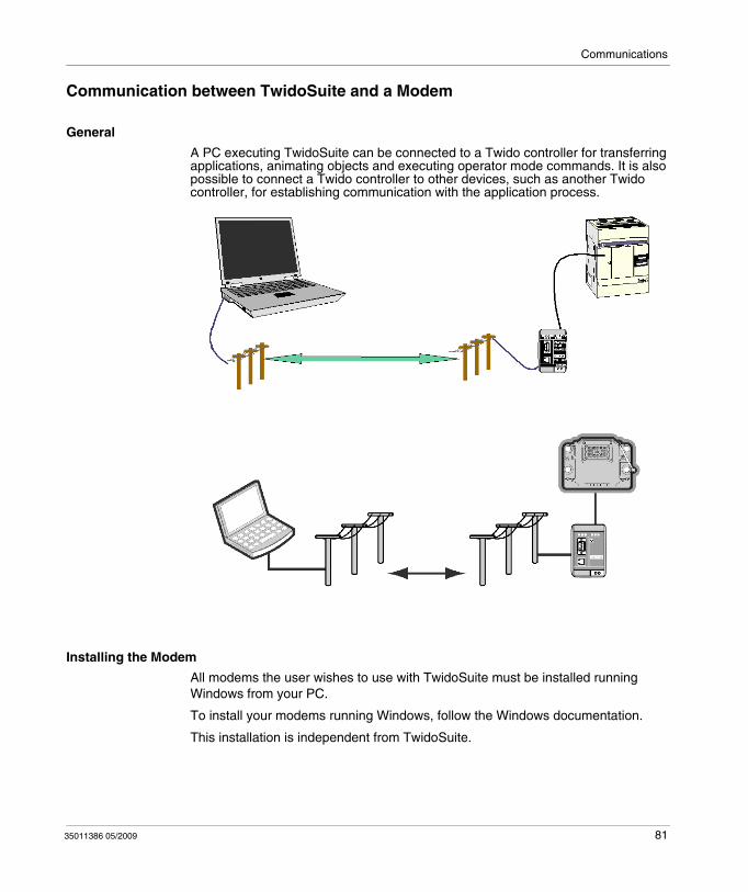
Communications
Communication between TwidoSuite and a Modem
General
A PC executing TwidoSuite can be connected to a Twido controller for transferring applications, animating objects and executing operator mode commands. It is also possible to connect a Twido controller to other devices, such as another Twido controller, for establishing communication with the application process.
Installing the Modem
All modems the user wishes to use with TwidoSuite must be installed running Windows from your PC.
To install your modems running Windows, follow the Windows documentation.
This installation is independent from TwidoSuite.
35011386 05/2009 81
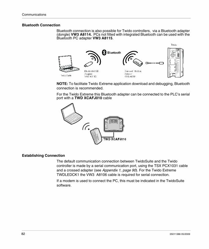
Communications
Bluetooth Connection
Bluetooth connection is also possible for Twido controllers, via a Bluetooth adapter (dongle) VW3 A8114. PCs not fitted with integrated Bluetooth can be used with the Bluetooth PC adapter VW3 A8115.
NOTE: To facilitate Twido Extreme application download and debugging, Bluetooth connection is recommended.
For the Twido Extreme this Bluetooth adapter can be connected to the PLC’s serial port with a TWD XCAFJ010 cable
Establishing Connection
The default communication connection between TwidoSuite and the Twido controller is made by a serial communication port, using the TSX PCX1031 cable and a crossed adapter (see Appendix 1, page 90). For the Twido Extreme TWDLEDCK1 the VW3 A8106 cable is required for serial connection.
If a modem is used to connect the PC, this must be indicated in the TwidoSuite software.
82 35011386 05/2009
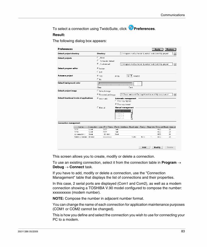
Communications
To select a connection using TwidoSuite, click Preferences.
Result:
The following dialog box appears:
This screen allows you to create, modify or delete a connection.
To use an existing connection, select it from the connection table in Program → Debug → Connect task.
If you have to add, modify or delete a connection, use the "Connection Management" table that displays the list of connections and their properties.
In this case, 2 serial ports are displayed (Com1 and Com2), as well as a modem connection showing a TOSHIBA V.90 model configured to compose the number: xxxxxxxxxx (modem number).
NOTE: Compose the number in adjacent number format.
You can change the name of each connection for application maintenance purposes (COM1 or COM2 cannot be changed).
This is how you define and select the connection you wish to use for connecting your PC to a modem.
35011386 05/2009 83
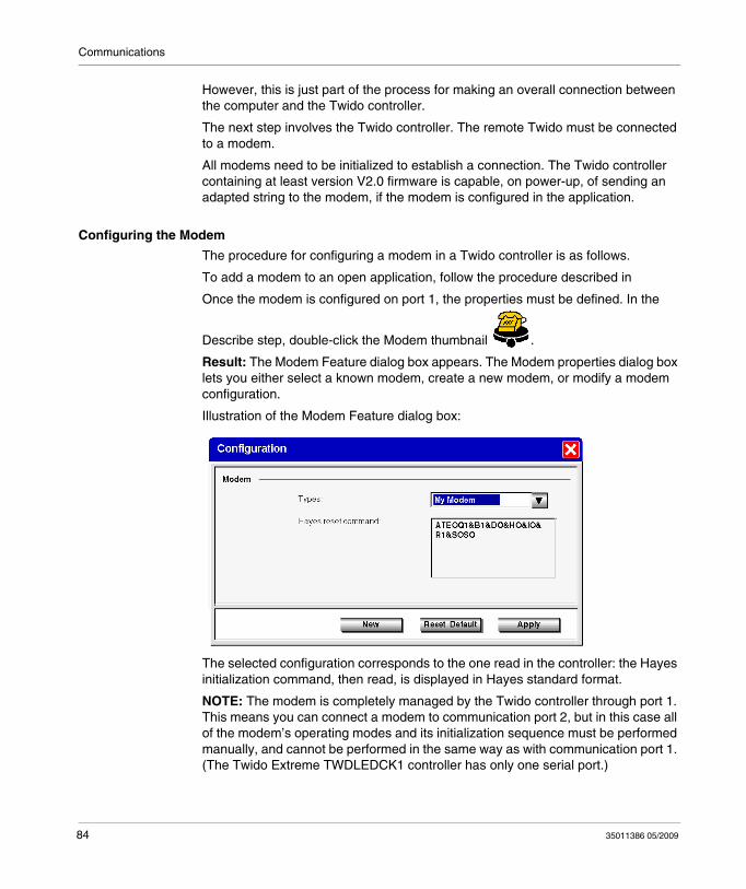
Communications
However, this is just part of the process for making an overall connection between the computer and the Twido controller.
The next step involves the Twido controller. The remote Twido must be connected to a modem.
All modems need to be initialized to establish a connection. The Twido controller containing at least version V2.0 firmware is capable, on power-up, of sending an adapted string to the modem, if the modem is configured in the application.
Configuring the Modem
The procedure for configuring a modem in a Twido controller is as follows.
To add a modem to an open application, follow the procedure described in
Once the modem is configured on port 1, the properties must be defined. In the
Describe step, double-click the Modem thumbnail .
Result: The Modem Feature dialog box appears. The Modem properties dialog box lets you either select a known modem, create a new modem, or modify a modem configuration.
Illustration of the Modem Feature dialog box:
The selected configuration corresponds to the one read in the controller: the Hayes initialization command, then read, is displayed in Hayes standard format.
NOTE: The modem is completely managed by the Twido controller through port 1. This means you can connect a modem to communication port 2, but in this case all of the modem’s operating modes and its initialization sequence must be performed manually, and cannot be performed in the same way as with communication port 1. (The Twido Extreme TWDLEDCK1 controller has only one serial port.)
84 35011386 05/2009
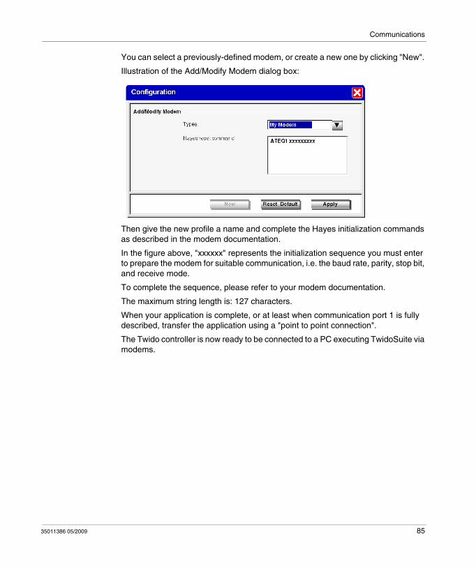
Communications
You can select a previously-defined modem, or create a new one by clicking "New".
Illustration of the Add/Modify Modem dialog box:
Then give the new profile a name and complete the Hayes initialization commands as described in the modem documentation.
In the figure above, "xxxxxx" represents the initialization sequence you must enter to prepare the modem for suitable communication, i.e. the baud rate, parity, stop bit, and receive mode.
To complete the sequence, please refer to your modem documentation.
The maximum string length is: 127 characters.
When your application is complete, or at least when communication port 1 is fully described, transfer the application using a "point to point connection".
The Twido controller is now ready to be connected to a PC executing TwidoSuite via modems.
35011386 05/2009 85
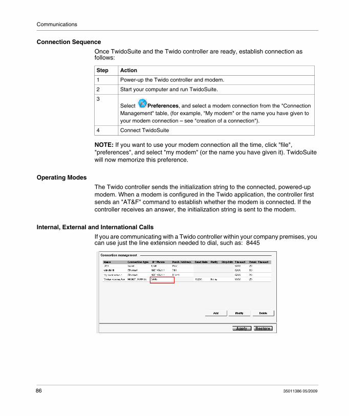
Communications
Connection Sequence
Once TwidoSuite and the Twido controller are ready, establish connection as follows:
NOTE: If you want to use your modem connection all the time, click "file", "preferences", and select "my modem" (or the name you have given it). TwidoSuite will now memorize this preference.
Operating Modes
The Twido controller sends the initialization string to the connected, powered-up modem. When a modem is configured in the Twido application, the controller first sends an "AT&F" command to establish whether the modem is connected. If the controller receives an answer, the initialization string is sent to the modem.
Internal, External and International Calls
If you are communicating with a Twido controller within your company premises, you can use just the line extension needed to dial, such as: 8445
Step Action
1 Power-up the Twido controller and modem.
2 Start your computer and run TwidoSuite.
3Select Preferences, and select a modem connection from the "Connection Management" table, (for example, "My modem" or the name you have given to your modem connection – see "creation of a connection").
4 Connect TwidoSuite
86 35011386 05/2009
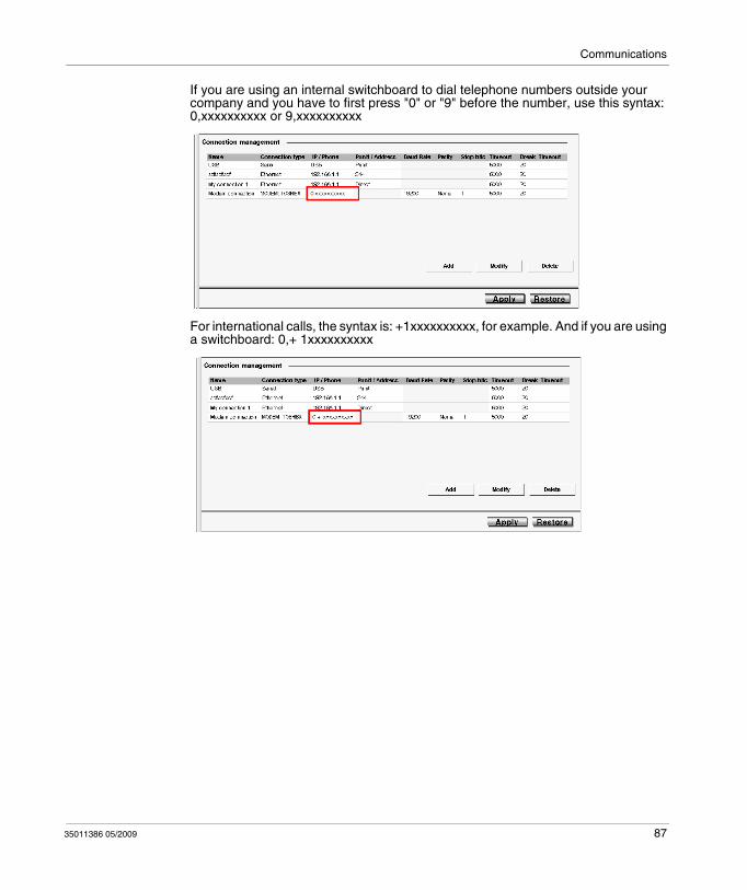
Communications
If you are using an internal switchboard to dial telephone numbers outside your company and you have to first press "0" or "9" before the number, use this syntax: 0,xxxxxxxxxx or 9,xxxxxxxxxx
For international calls, the syntax is: +1xxxxxxxxxx, for example. And if you are using a switchboard: 0,+ 1xxxxxxxxxx
35011386 05/2009 87
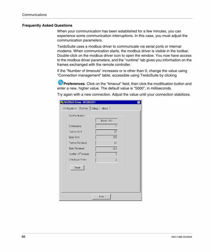
Communications
Frequently Asked Questions
When your communication has been established for a few minutes, you can experience some communication interruptions. In this case, you must adjust the communication parameters.
TwidoSuite uses a modbus driver to communicate via serial ports or internal modems. When communication starts, the modbus driver is visible in the toolbar. Double-click on the modbus driver icon to open the window. You now have access to the modbus driver parameters, and the "runtime" tab gives you information on the frames exchanged with the remote controller.
If the "Number of timeouts" increases or is other than 0, change the value using "Connection management" table, accessible using TwidoSuite by clicking
Preferences. Click on the "timeout" field, then click the modification button and enter a new, higher value. The default value is "5000", in milliseconds.
Try again with a new connection. Adjust the value until your connection stabilizes.
88 35011386 05/2009
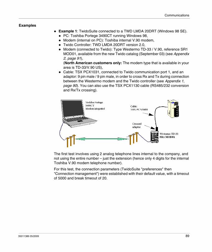
Communications
Examples
Example 1: TwidoSuite connected to a TWD LMDA 20DRT (Windows 98 SE).PC: Toshiba Portege 3490CT running Windows 98,Modem (internal on PC): Toshiba internal V.90 modem,Twido Controller: TWD LMDA 20DRT version 2.0,Modem (connected to Twido): Type Westermo TD-33 / V.90, reference SR1 MOD01, available from the new Twido catalog (September 03) (see Appendix 2, page 91),(North American customers only: The modem type that is available in your area is TD-33/V.90 US),Cable: TSX PCX1031, connected to Twido communication port 1, and an adaptor: 9 pin male / 9 pin male, in order to cross Rx and Tx during connection between the Westermo modem and the Twido controller (see Appendix 1, page 90). You can also use the TSX PCX1130 cable (RS485/232 conversion and Rx/Tx crossing).
The first test involves using 2 analog telephone lines internal to the company, and not using the entire number – just the extension (hence only 4 digits for the internal Toshiba V.90 modem telephone number).
For this test, the connection parameters (TwidoSuite "preferences" then "Connection management") were established with their default value, with a timeout of 5000 and break timeout of 20.
35011386 05/2009 89
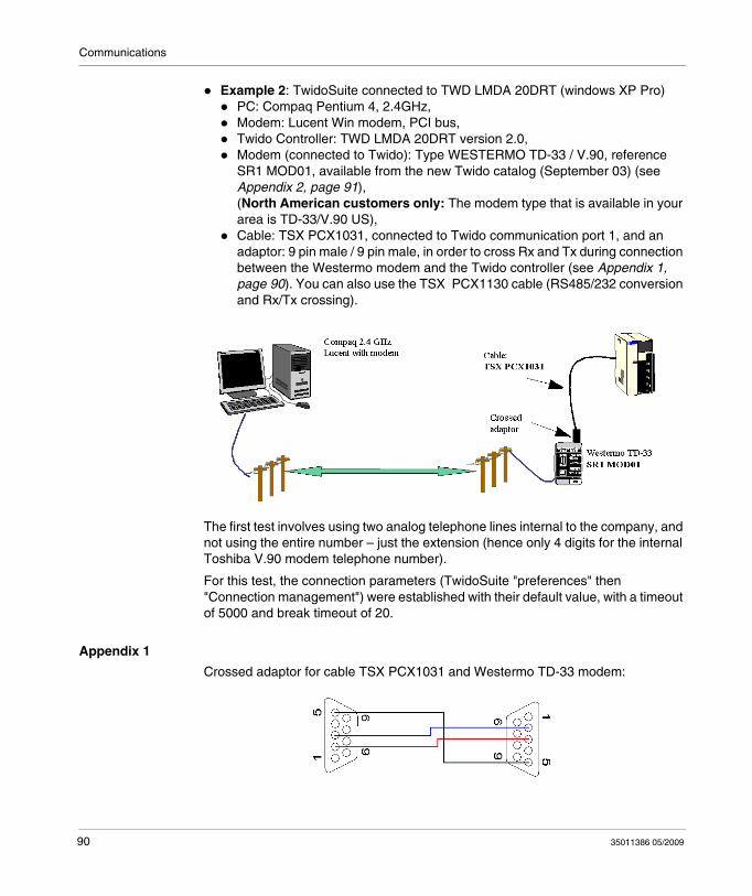
Communications
Example 2: TwidoSuite connected to TWD LMDA 20DRT (windows XP Pro)PC: Compaq Pentium 4, 2.4GHz,Modem: Lucent Win modem, PCI bus,Twido Controller: TWD LMDA 20DRT version 2.0,Modem (connected to Twido): Type WESTERMO TD-33 / V.90, reference SR1 MOD01, available from the new Twido catalog (September 03) (see Appendix 2, page 91),(North American customers only: The modem type that is available in your area is TD-33/V.90 US),Cable: TSX PCX1031, connected to Twido communication port 1, and an adaptor: 9 pin male / 9 pin male, in order to cross Rx and Tx during connection between the Westermo modem and the Twido controller (see Appendix 1, page 90). You can also use the TSX PCX1130 cable (RS485/232 conversion and Rx/Tx crossing).
The first test involves using two analog telephone lines internal to the company, and not using the entire number – just the extension (hence only 4 digits for the internal Toshiba V.90 modem telephone number).
For this test, the connection parameters (TwidoSuite "preferences" then "Connection management") were established with their default value, with a timeout of 5000 and break timeout of 20.
Appendix 1
Crossed adaptor for cable TSX PCX1031 and Westermo TD-33 modem:
90 35011386 05/2009
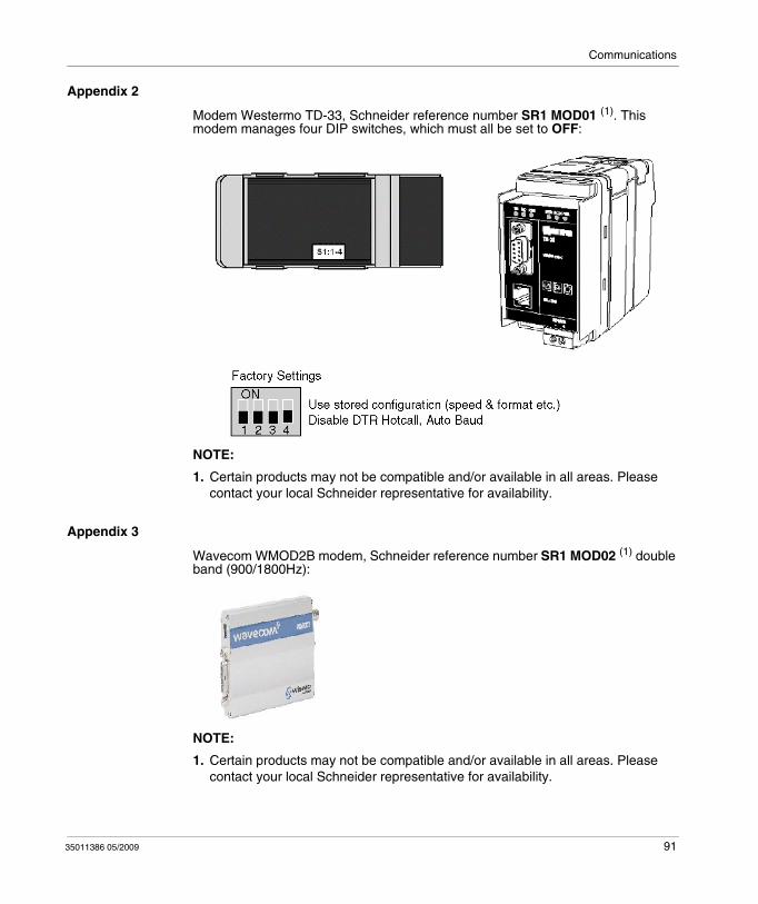
Communications
Appendix 2
Modem Westermo TD-33, Schneider reference number SR1 MOD01 (1). This modem manages four DIP switches, which must all be set to OFF:
NOTE:
1. Certain products may not be compatible and/or available in all areas. Please contact your local Schneider representative for availability.
Appendix 3
Wavecom WMOD2B modem, Schneider reference number SR1 MOD02 (1) double band (900/1800Hz):
NOTE:
1. Certain products may not be compatible and/or available in all areas. Please contact your local Schneider representative for availability.
35011386 05/2009 91

Communications
Appendix 4
Reference numbers of the products used in this document:
Twido product: TWD LMDA 20DRT,TwidoSuite software: TWD SPU 1002 V10M,TSX PCX1031 cable,TSX PCX1130 cable,
RTU modem: Westermo TD-33 / V90 SR1 MOD01 (1),
GSM modem: Wavecom WMOD2B SR1 MOD02 (1).
NOTE:
1. Certain products may not be compatible and/or available in all areas. Please contact your local Schneider representative for availability.
92 35011386 05/2009
Communications
Remote Link Communications
Introduction
The remote link is a high-speed master/slave bus designed to communicate a small amount of data between the master controller and up to seven remote (slave) controllers. Application or I/O data is transferred, depending on the configuration of the remote controllers. A mixture of remote controller types is possible, where some can be remote I/O and some can be peers.
NOTE: Remote Link communications are not supported by the TWDLEDCK1 Twido Extreme controller.
NOTE: The master controller contains information regarding the address of a remote I/O. It does not know which specific controller is at the address. Therefore, the master cannot validate that all the remote inputs and outputs used in the user application actually exist. Take care that these remote inputs or outputs actually exist.
NOTE: The remote I/O bus and the protocol used is proprietary and no third party devices are allowed on the network.
NOTE: The remote link requires an EIA RS485 connection and can only run on one communications port at a time.
WARNINGUNINTENDED EQUIPMENT OPERATION
Be sure that there is only one master controller on a remote link .Be sure that all slaves have unique addresses. No two slaves should have the same address.
Failure to follow these instructions can result in death, serious injury, or equipment damage.
35011386 05/2009 93
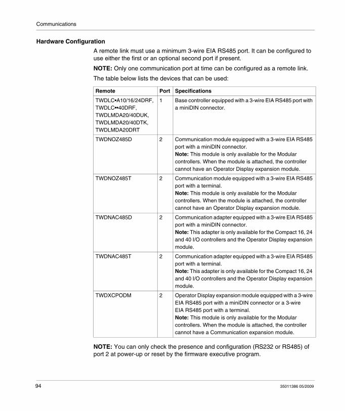
Communications
Hardware Configuration
A remote link must use a minimum 3-wire EIA RS485 port. It can be configured to use either the first or an optional second port if present.
NOTE: Only one communication port at time can be configured as a remote link.
The table below lists the devices that can be used:
NOTE: You can only check the presence and configuration (RS232 or RS485) of port 2 at power-up or reset by the firmware executive program.
Remote Port Specifications
TWDLC•A10/16/24DRF, TWDLC••40DRF, TWDLMDA20/40DUK, TWDLMDA20/40DTK, TWDLMDA20DRT
1 Base controller equipped with a 3-wire EIA RS485 port with a miniDIN connector.
TWDNOZ485D 2 Communication module equipped with a 3-wire EIA RS485 port with a miniDIN connector.Note: This module is only available for the Modular controllers. When the module is attached, the controller cannot have an Operator Display expansion module.
TWDNOZ485T 2 Communication module equipped with a 3-wire EIA RS485 port with a terminal.Note: This module is only available for the Modular controllers. When the module is attached, the controller cannot have an Operator Display expansion module.
TWDNAC485D 2 Communication adapter equipped with a 3-wire EIA RS485 port with a miniDIN connector.Note: This adapter is only available for the Compact 16, 24 and 40 I/O controllers and the Operator Display expansion module.
TWDNAC485T 2 Communication adapter equipped with a 3-wire EIA RS485 port with a terminal.Note: This adapter is only available for the Compact 16, 24 and 40 I/O controllers and the Operator Display expansion module.
TWDXCPODM 2 Operator Display expansion module equipped with a 3-wire EIA RS485 port with a miniDIN connector or a 3-wire EIA RS485 port with a terminal.Note: This module is only available for the Modular controllers. When the module is attached, the controller cannot have a Communication expansion module.
94 35011386 05/2009
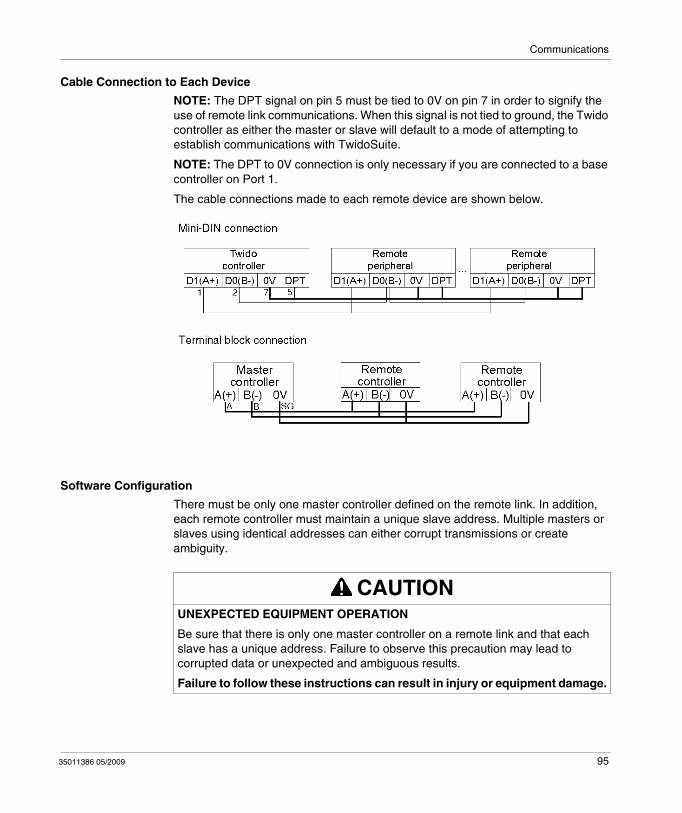
Communications
Cable Connection to Each Device
NOTE: The DPT signal on pin 5 must be tied to 0V on pin 7 in order to signify the use of remote link communications. When this signal is not tied to ground, the Twido controller as either the master or slave will default to a mode of attempting to establish communications with TwidoSuite.
NOTE: The DPT to 0V connection is only necessary if you are connected to a base controller on Port 1.
The cable connections made to each remote device are shown below.
Software Configuration
There must be only one master controller defined on the remote link. In addition, each remote controller must maintain a unique slave address. Multiple masters or slaves using identical addresses can either corrupt transmissions or create ambiguity.
CAUTIONUNEXPECTED EQUIPMENT OPERATION
Be sure that there is only one master controller on a remote link and that each slave has a unique address. Failure to observe this precaution may lead to corrupted data or unexpected and ambiguous results.
Failure to follow these instructions can result in injury or equipment damage.
35011386 05/2009 95
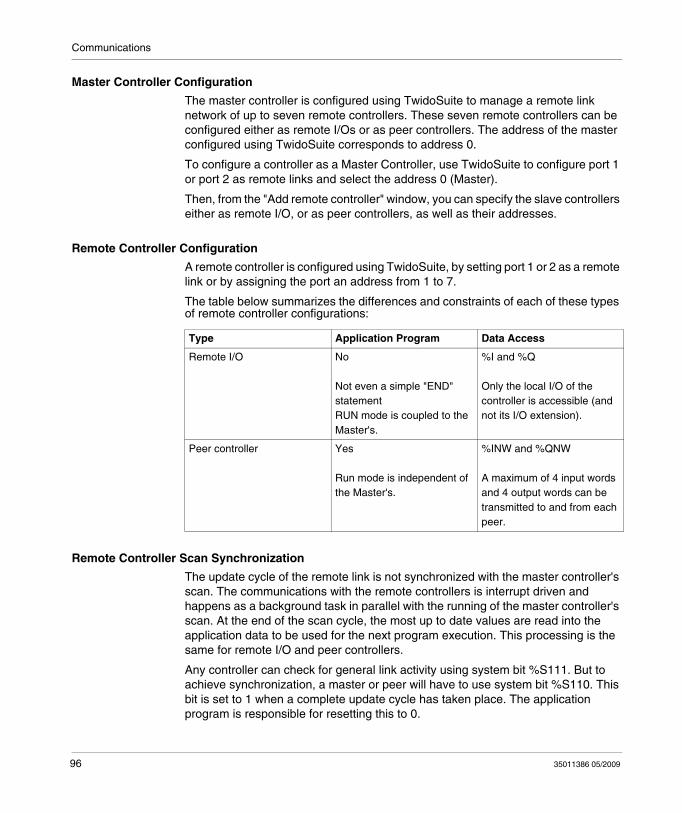
Communications
Master Controller Configuration
The master controller is configured using TwidoSuite to manage a remote link network of up to seven remote controllers. These seven remote controllers can be configured either as remote I/Os or as peer controllers. The address of the master configured using TwidoSuite corresponds to address 0.
To configure a controller as a Master Controller, use TwidoSuite to configure port 1 or port 2 as remote links and select the address 0 (Master).
Then, from the "Add remote controller" window, you can specify the slave controllers either as remote I/O, or as peer controllers, as well as their addresses.
Remote Controller Configuration
A remote controller is configured using TwidoSuite, by setting port 1 or 2 as a remote link or by assigning the port an address from 1 to 7.
The table below summarizes the differences and constraints of each of these types of remote controller configurations:
Remote Controller Scan Synchronization
The update cycle of the remote link is not synchronized with the master controller's scan. The communications with the remote controllers is interrupt driven and happens as a background task in parallel with the running of the master controller's scan. At the end of the scan cycle, the most up to date values are read into the application data to be used for the next program execution. This processing is the same for remote I/O and peer controllers.
Any controller can check for general link activity using system bit %S111. But to achieve synchronization, a master or peer will have to use system bit %S110. This bit is set to 1 when a complete update cycle has taken place. The application program is responsible for resetting this to 0.
Type Application Program Data Access
Remote I/O No
Not even a simple "END" statementRUN mode is coupled to the Master's.
%I and %Q
Only the local I/O of the controller is accessible (and not its I/O extension).
Peer controller Yes
Run mode is independent of the Master's.
%INW and %QNW
A maximum of 4 input words and 4 output words can be transmitted to and from each peer.
96 35011386 05/2009
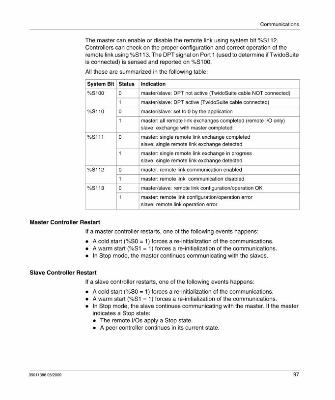
Communications
The master can enable or disable the remote link using system bit %S112. Controllers can check on the proper configuration and correct operation of the remote link using %S113. The DPT signal on Port 1 (used to determine if TwidoSuite is connected) is sensed and reported on %S100.
All these are summarized in the following table:
Master Controller Restart
If a master controller restarts, one of the following events happens:
A cold start (%S0 = 1) forces a re-initialization of the communications.A warm start (%S1 = 1) forces a re-initialization of the communications.In Stop mode, the master continues communicating with the slaves.
Slave Controller Restart
If a slave controller restarts, one of the following events happens:
A cold start (%S0 = 1) forces a re-initialization of the communications.A warm start (%S1 = 1) forces a re-initialization of the communications.In Stop mode, the slave continues communicating with the master. If the master indicates a Stop state:
The remote I/Os apply a Stop state. A peer controller continues in its current state.
System Bit Status Indication
%S100 0 master/slave: DPT not active (TwidoSuite cable NOT connected)
1 master/slave: DPT active (TwidoSuite cable connected)
%S110 0 master/slave: set to 0 by the application
1 master: all remote link exchanges completed (remote I/O only)slave: exchange with master completed
%S111 0 master: single remote link exchange completedslave: single remote link exchange detected
1 master: single remote link exchange in progressslave: single remote link exchange detected
%S112 0 master: remote link communication enabled
1 master: remote link communication disabled
%S113 0 master/slave: remote link configuration/operation OK
1 master: remote link configuration/operation errorslave: remote link operation error
35011386 05/2009 97
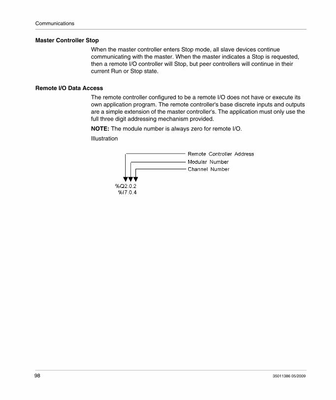
Communications
Master Controller Stop
When the master controller enters Stop mode, all slave devices continue communicating with the master. When the master indicates a Stop is requested, then a remote I/O controller will Stop, but peer controllers will continue in their current Run or Stop state.
Remote I/O Data Access
The remote controller configured to be a remote I/O does not have or execute its own application program. The remote controller's base discrete inputs and outputs are a simple extension of the master controller's. The application must only use the full three digit addressing mechanism provided.
NOTE: The module number is always zero for remote I/O.
Illustration
98 35011386 05/2009
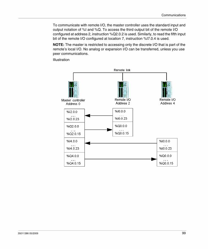
Communications
To communicate with remote I/O, the master controller uses the standard input and output notation of %I and %Q. To access the third output bit of the remote I/O configured at address 2, instruction %Q2.0.2 is used. Similarly, to read the fifth input bit of the remote I/O configured at location 7, instruction %I7.0.4 is used.
NOTE: The master is restricted to accessing only the discrete I/O that is part of the remote’s local I/O. No analog or expansion I/O can be transferred, unless you use peer communications.
Illustration
35011386 05/2009 99
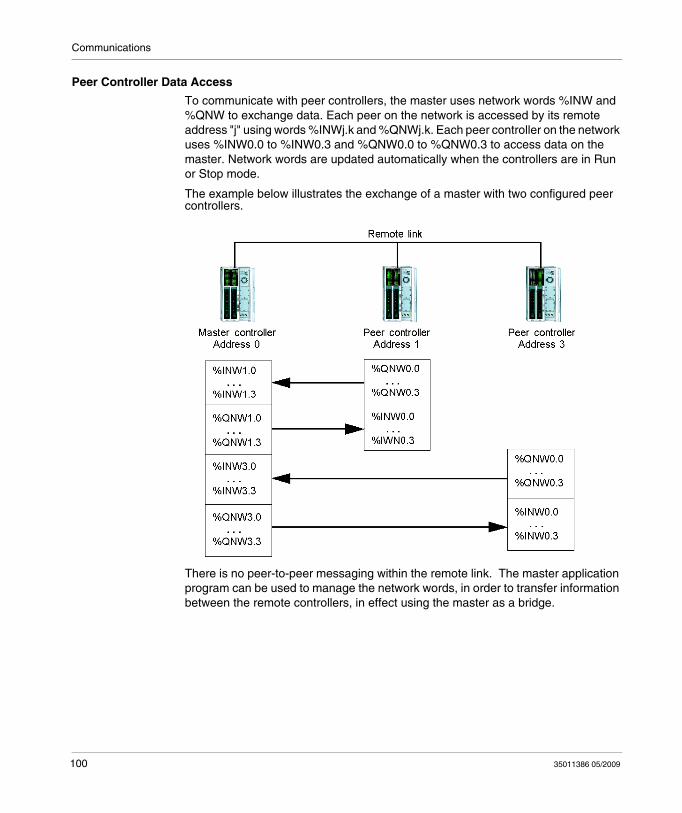
Communications
Peer Controller Data Access
To communicate with peer controllers, the master uses network words %INW and %QNW to exchange data. Each peer on the network is accessed by its remote address "j" using words %INWj.k and %QNWj.k. Each peer controller on the network uses %INW0.0 to %INW0.3 and %QNW0.0 to %QNW0.3 to access data on the master. Network words are updated automatically when the controllers are in Run or Stop mode.
The example below illustrates the exchange of a master with two configured peer controllers.
There is no peer-to-peer messaging within the remote link. The master application program can be used to manage the network words, in order to transfer information between the remote controllers, in effect using the master as a bridge.
100 35011386 05/2009
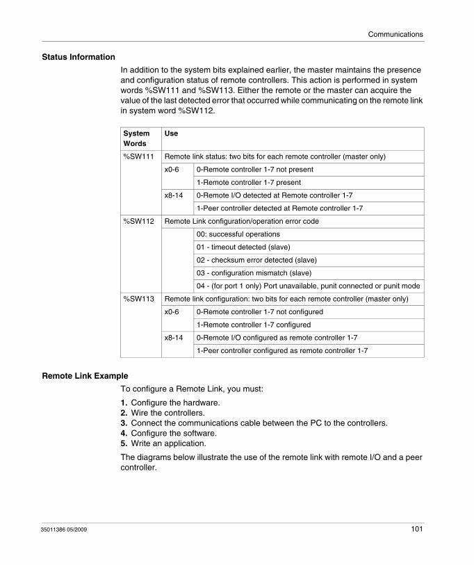
Communications
Status Information
In addition to the system bits explained earlier, the master maintains the presence and configuration status of remote controllers. This action is performed in system words %SW111 and %SW113. Either the remote or the master can acquire the value of the last detected error that occurred while communicating on the remote link in system word %SW112.
Remote Link Example
To configure a Remote Link, you must:
1. Configure the hardware.2. Wire the controllers.3. Connect the communications cable between the PC to the controllers.4. Configure the software.5. Write an application.
The diagrams below illustrate the use of the remote link with remote I/O and a peer controller.
System Words
Use
%SW111 Remote link status: two bits for each remote controller (master only)
x0-6 0-Remote controller 1-7 not present
1-Remote controller 1-7 present
x8-14 0-Remote I/O detected at Remote controller 1-7
1-Peer controller detected at Remote controller 1-7
%SW112 Remote Link configuration/operation error code
00: successful operations
01 - timeout detected (slave)
02 - checksum error detected (slave)
03 - configuration mismatch (slave)
04 - (for port 1 only) Port unavailable, punit connected or punit mode
%SW113 Remote link configuration: two bits for each remote controller (master only)
x0-6 0-Remote controller 1-7 not configured
1-Remote controller 1-7 configured
x8-14 0-Remote I/O configured as remote controller 1-7
1-Peer controller configured as remote controller 1-7
35011386 05/2009 101
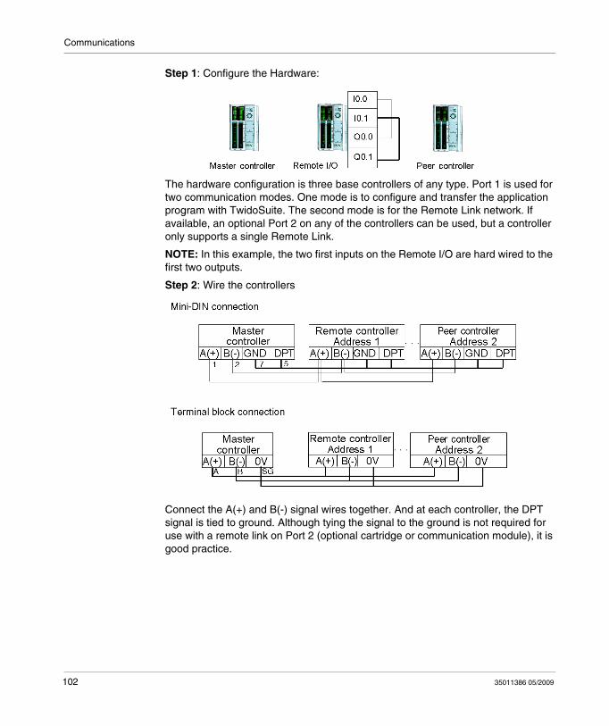
Communications
Step 1: Configure the Hardware:
The hardware configuration is three base controllers of any type. Port 1 is used for two communication modes. One mode is to configure and transfer the application program with TwidoSuite. The second mode is for the Remote Link network. If available, an optional Port 2 on any of the controllers can be used, but a controller only supports a single Remote Link.
NOTE: In this example, the two first inputs on the Remote I/O are hard wired to the first two outputs.
Step 2: Wire the controllers
Connect the A(+) and B(-) signal wires together. And at each controller, the DPT signal is tied to ground. Although tying the signal to the ground is not required for use with a remote link on Port 2 (optional cartridge or communication module), it is good practice.
102 35011386 05/2009
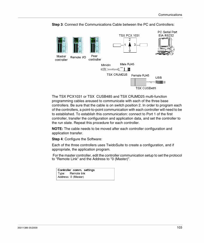
Communications
Step 3: Connect the Communications Cable between the PC and Controllers:
The TSX PCX1031 or TSX CUSB485 and TSX CRJMD25 multi-function programming cables areused to communicate with each of the three base controllers. Be sure that the cable is on switch position 2. In order to program each of the controllers, a point-to-point communication with each controller will need to be to established. To establish this communication: connect to Port 1 of the first controller, transfer the configuration and application data, and set the controller to the run state. Repeat this procedure for each controller.
NOTE: The cable needs to be moved after each controller configuration and application transfer.
Step 4: Configure the Software:
Each of the three controllers uses TwidoSuite to create a configuration, and if appropriate, the application program.
For the master controller, edit the controller communication setup to set the protocol to "Remote Link" and the Address to "0 (Master)".
35011386 05/2009 103
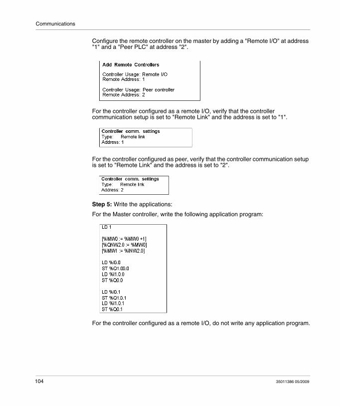
Communications
Configure the remote controller on the master by adding a "Remote I/O" at address "1" and a "Peer PLC" at address "2".
For the controller configured as a remote I/O, verify that the controller communication setup is set to "Remote Link" and the address is set to "1".
For the controller configured as peer, verify that the controller communication setup is set to "Remote Link" and the address is set to "2".
Step 5: Write the applications:
For the Master controller, write the following application program:
For the controller configured as a remote I/O, do not write any application program.
104 35011386 05/2009

Communications
For the controller configured as peer, write the following application:
In this example, the master application increments an internal memory word and communicates this to the peer controller using a single network word. The peer controller takes the word received from the master and echoes it back. In the master, a different memory word receives and stores this transmission.
For communication with the remote I/O controller, the master sends its local inputs to the remote I/O's outputs. With the external I/O hard wiring of the remote I/O, the signals are returned and retrieved by the master.
35011386 05/2009 105
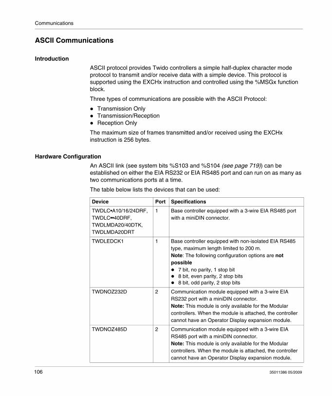
Communications
ASCII Communications
Introduction
ASCII protocol provides Twido controllers a simple half-duplex character mode protocol to transmit and/or receive data with a simple device. This protocol is supported using the EXCHx instruction and controlled using the %MSGx function block.
Three types of communications are possible with the ASCII Protocol:
Transmission OnlyTransmission/ReceptionReception Only
The maximum size of frames transmitted and/or received using the EXCHx instruction is 256 bytes.
Hardware Configuration
An ASCII link (see system bits %S103 and %S104 (see page 719)) can be established on either the EIA RS232 or EIA RS485 port and can run on as many as two communications ports at a time.
The table below lists the devices that can be used:
Device Port Specifications
TWDLC•A10/16/24DRF, TWDLC••40DRF, TWDLMDA20/40DTK, TWDLMDA20DRT
1 Base controller equipped with a 3-wire EIA RS485 port with a miniDIN connector.
TWDLEDCK1 1 Base controller equipped with non-isolated EIA RS485 type, maximum length limited to 200 m.Note: The following configuration options are not possible
7 bit, no parity, 1 stop bit8 bit, even parity, 2 stop bits8 bit, odd parity, 2 stop bits
TWDNOZ232D 2 Communication module equipped with a 3-wire EIA RS232 port with a miniDIN connector.Note: This module is only available for the Modular controllers. When the module is attached, the controller cannot have an Operator Display expansion module.
TWDNOZ485D 2 Communication module equipped with a 3-wire EIA RS485 port with a miniDIN connector.Note: This module is only available for the Modular controllers. When the module is attached, the controller cannot have an Operator Display expansion module.
106 35011386 05/2009
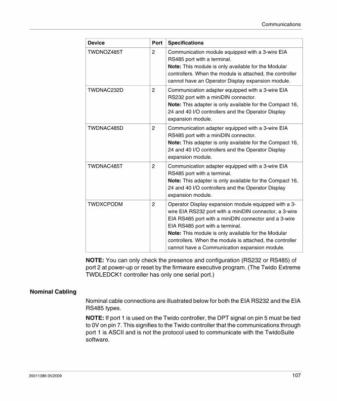
Communications
NOTE: You can only check the presence and configuration (RS232 or RS485) of port 2 at power-up or reset by the firmware executive program. (The Twido Extreme TWDLEDCK1 controller has only one serial port.)
Nominal Cabling
Nominal cable connections are illustrated below for both the EIA RS232 and the EIA RS485 types.
NOTE: If port 1 is used on the Twido controller, the DPT signal on pin 5 must be tied to 0V on pin 7. This signifies to the Twido controller that the communications through port 1 is ASCII and is not the protocol used to communicate with the TwidoSuite software.
TWDNOZ485T 2 Communication module equipped with a 3-wire EIA RS485 port with a terminal.Note: This module is only available for the Modular controllers. When the module is attached, the controller cannot have an Operator Display expansion module.
TWDNAC232D 2 Communication adapter equipped with a 3-wire EIA RS232 port with a miniDIN connector.Note: This adapter is only available for the Compact 16, 24 and 40 I/O controllers and the Operator Display expansion module.
TWDNAC485D 2 Communication adapter equipped with a 3-wire EIA RS485 port with a miniDIN connector.Note: This adapter is only available for the Compact 16, 24 and 40 I/O controllers and the Operator Display expansion module.
TWDNAC485T 2 Communication adapter equipped with a 3-wire EIA RS485 port with a terminal.Note: This adapter is only available for the Compact 16, 24 and 40 I/O controllers and the Operator Display expansion module.
TWDXCPODM 2 Operator Display expansion module equipped with a 3-wire EIA RS232 port with a miniDIN connector, a 3-wire EIA RS485 port with a miniDIN connector and a 3-wire EIA RS485 port with a terminal.Note: This module is only available for the Modular controllers. When the module is attached, the controller cannot have a Communication expansion module.
Device Port Specifications
35011386 05/2009 107
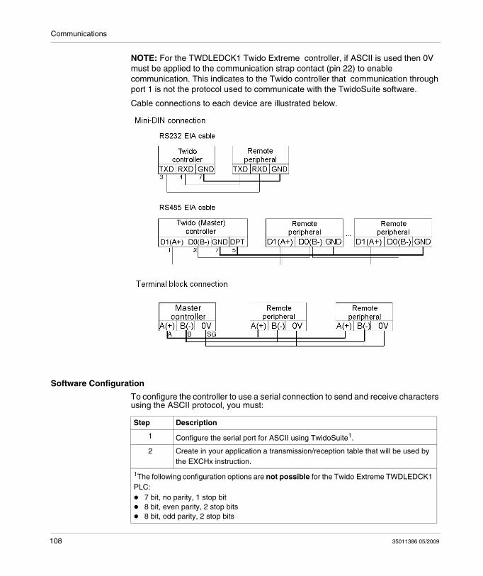
Communications
NOTE: For the TWDLEDCK1 Twido Extreme controller, if ASCII is used then 0V must be applied to the communication strap contact (pin 22) to enable communication. This indicates to the Twido controller that communication through port 1 is not the protocol used to communicate with the TwidoSuite software.
Cable connections to each device are illustrated below.
Software Configuration
To configure the controller to use a serial connection to send and receive characters using the ASCII protocol, you must:
Step Description
1 Configure the serial port for ASCII using TwidoSuite1.
2 Create in your application a transmission/reception table that will be used by the EXCHx instruction.
1The following configuration options are not possible for the Twido Extreme TWDLEDCK1 PLC:
7 bit, no parity, 1 stop bit8 bit, even parity, 2 stop bits8 bit, odd parity, 2 stop bits
108 35011386 05/2009
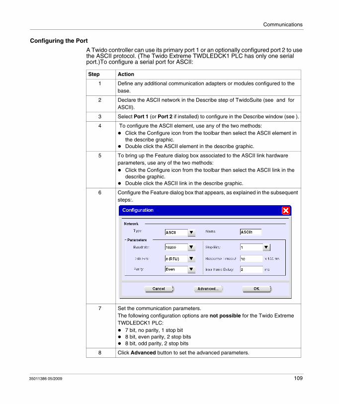
Communications
Configuring the Port
A Twido controller can use its primary port 1 or an optionally configured port 2 to use the ASCII protocol. (The Twido Extreme TWDLEDCK1 PLC has only one serial port.)To configure a serial port for ASCII:
Step Action
1 Define any additional communication adapters or modules configured to the base.
2 Declare the ASCII network in the Describe step of TwidoSuite (see and for ASCII).
3 Select Port 1 (or Port 2 if installed) to configure in the Describe window (see ).
4 To configure the ASCII element, use any of the two methods:Click the Configure icon from the toolbar then select the ASCII element in the describe graphic.Double click the ASCII element in the describe graphic.
5 To bring up the Feature dialog box associated to the ASCII link hardware parameters, use any of the two methods:
Click the Configure icon from the toolbar then select the ASCII link in the describe graphic.Double click the ASCII link in the describe graphic.
6 Configure the Feature dialog box that appears, as explained in the subsequent steps:.
7 Set the communication parameters.The following configuration options are not possible for the Twido Extreme TWDLEDCK1 PLC:
7 bit, no parity, 1 stop bit8 bit, even parity, 2 stop bits8 bit, odd parity, 2 stop bits
8 Click Advanced button to set the advanced parameters.
35011386 05/2009 109
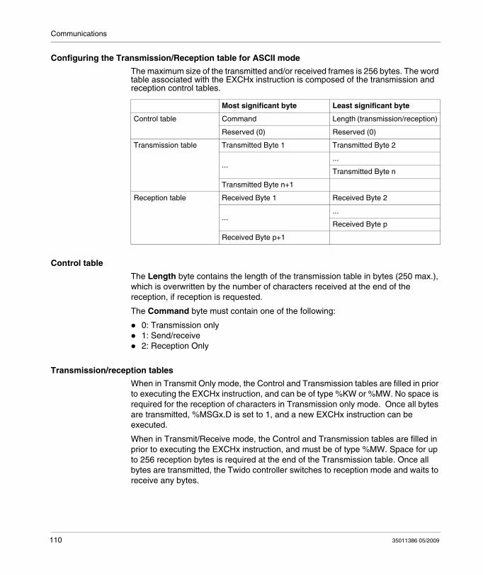
Communications
Configuring the Transmission/Reception table for ASCII mode
The maximum size of the transmitted and/or received frames is 256 bytes. The word table associated with the EXCHx instruction is composed of the transmission and reception control tables.
Control table
The Length byte contains the length of the transmission table in bytes (250 max.), which is overwritten by the number of characters received at the end of the reception, if reception is requested.
The Command byte must contain one of the following:
0: Transmission only1: Send/receive2: Reception Only
Transmission/reception tables
When in Transmit Only mode, the Control and Transmission tables are filled in prior to executing the EXCHx instruction, and can be of type %KW or %MW. No space is required for the reception of characters in Transmission only mode. Once all bytes are transmitted, %MSGx.D is set to 1, and a new EXCHx instruction can be executed.
When in Transmit/Receive mode, the Control and Transmission tables are filled in prior to executing the EXCHx instruction, and must be of type %MW. Space for up to 256 reception bytes is required at the end of the Transmission table. Once all bytes are transmitted, the Twido controller switches to reception mode and waits to receive any bytes.
Most significant byte Least significant byte
Control table Command Length (transmission/reception)
Reserved (0) Reserved (0)
Transmission table Transmitted Byte 1 Transmitted Byte 2
......
Transmitted Byte n
Transmitted Byte n+1
Reception table Received Byte 1 Received Byte 2
......
Received Byte p
Received Byte p+1
110 35011386 05/2009
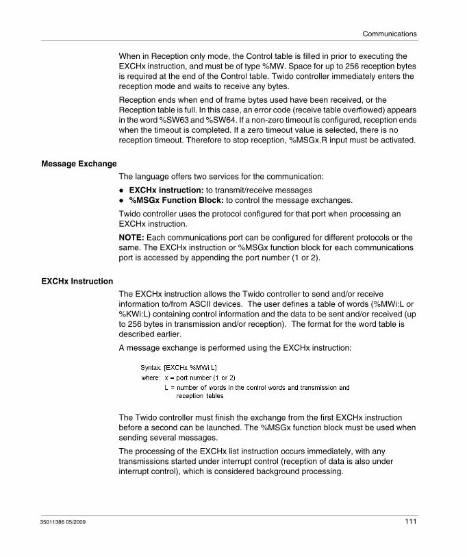
Communications
When in Reception only mode, the Control table is filled in prior to executing the EXCHx instruction, and must be of type %MW. Space for up to 256 reception bytes is required at the end of the Control table. Twido controller immediately enters the reception mode and waits to receive any bytes.
Reception ends when end of frame bytes used have been received, or the Reception table is full. In this case, an error code (receive table overflowed) appears in the word %SW63 and %SW64. If a non-zero timeout is configured, reception ends when the timeout is completed. If a zero timeout value is selected, there is no reception timeout. Therefore to stop reception, %MSGx.R input must be activated.
Message Exchange
The language offers two services for the communication:
EXCHx instruction: to transmit/receive messages%MSGx Function Block: to control the message exchanges.
Twido controller uses the protocol configured for that port when processing an EXCHx instruction.
NOTE: Each communications port can be configured for different protocols or the same. The EXCHx instruction or %MSGx function block for each communications port is accessed by appending the port number (1 or 2).
EXCHx Instruction
The EXCHx instruction allows the Twido controller to send and/or receive information to/from ASCII devices. The user defines a table of words (%MWi:L or %KWi:L) containing control information and the data to be sent and/or received (up to 256 bytes in transmission and/or reception). The format for the word table is described earlier.
A message exchange is performed using the EXCHx instruction:
The Twido controller must finish the exchange from the first EXCHx instruction before a second can be launched. The %MSGx function block must be used when sending several messages.
The processing of the EXCHx list instruction occurs immediately, with any transmissions started under interrupt control (reception of data is also under interrupt control), which is considered background processing.
35011386 05/2009 111
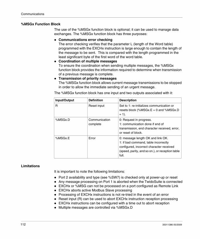
Communications
%MSGx Function Block
The use of the %MSGx function block is optional; it can be used to manage data exchanges. The %MSGx function block has three purposes:
Communications error checkingThe error checking verifies that the parameter L (length of the Word table) programmed with the EXCHx instruction is large enough to contain the length of the message to be sent. This is compared with the length programmed in the least significant byte of the first word of the word table.Coordination of multiple messagesTo ensure the coordination when sending multiple messages, the %MSGx function block provides the information required to determine when transmission of a previous message is complete.Transmission of priority messagesThe %MSGx function block allows current message transmissions to be stopped in order to allow the immediate sending of an urgent message.
The %MSGx function block has one input and two outputs associated with it:
Limitations
It is important to note the following limitations:
Port 2 availability and type (see %SW7) is checked only at power-up or resetAny message processing on Port 1 is aborted when the TwidoSuite is connectedEXCHx or %MSG can not be processed on a port configured as Remote LinkEXCHx aborts active Modbus Slave processingProcessing of EXCHx instructions is not re-tried in the event of an errorReset input (R) can be used to abort EXCHx instruction reception processingEXCHx instructions can be configured with a time out to abort receptionMultiple messages are controlled via %MSGx.D
Input/Output Definition Description
R Reset input Set to 1: re-initializes communication or resets block (%MSGx.E = 0 and %MSGx.D = 1).
%MSGx.D Communication complete
0: Request in progress.1: communication done if end of transmission, end character received, error, or reset of block.
%MSGx.E Error 0: message length OK and link OK.1: if bad command, table incorrectly configured, incorrect character received (speed, parity, and so on.), or reception table full.
112 35011386 05/2009
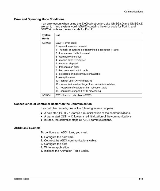
Communications
Error and Operating Mode Conditions
If an error occurs when using the EXCHx instruction, bits %MSGx.D and %MSGx.E are set to 1 and system word %SW63 contains the error code for Port 1, and %SW64 contains the error code for Port 2.
Consequence of Controller Restart on the Communication
If a controller restarts, one of the following events happens:
A cold start (%S0 = 1) forces a re-initialization of the communications.A warm start (%S1 = 1) forces a re-initialization of the communications.In Stop, the controller stops all ASCII communications.
ASCII Link Example
To configure an ASCII Link, you must:
1. Configure the hardware.2. Connect the ASCII communications cable.3. Configure the port.4. Write an application.5. Initialize the Animation Table Editor.
System Words
Use
%SW63 EXCH1 error code:0 - operation was successful1 – number of bytes to be transmitted is too great (> 250)2 - transmission table too small3 - word table too small4 - receive table overflowed5 - time-out elapsed6 - transmission error7 - bad command within table8 - selected port not configured/available9 - reception error10 - cannot use %KW if receiving11 - transmission offset larger than transmission table12 - reception offset larger than reception table13 - controller stopped EXCH processing
%SW64 EXCH2 error code: See %SW63.
35011386 05/2009 113
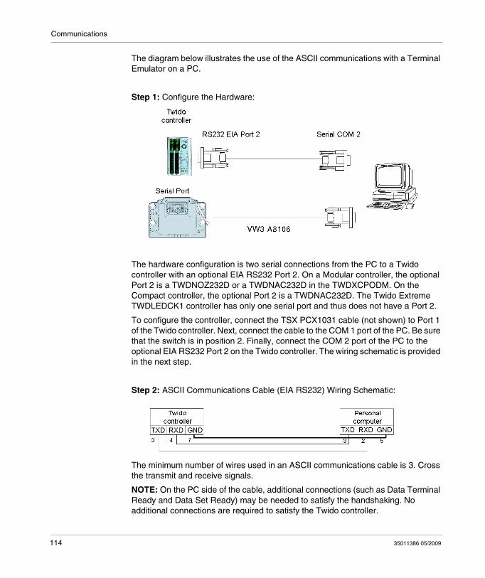
Communications
The diagram below illustrates the use of the ASCII communications with a Terminal Emulator on a PC.
Step 1: Configure the Hardware:
The hardware configuration is two serial connections from the PC to a Twido controller with an optional EIA RS232 Port 2. On a Modular controller, the optional Port 2 is a TWDNOZ232D or a TWDNAC232D in the TWDXCPODM. On the Compact controller, the optional Port 2 is a TWDNAC232D. The Twido Extreme TWDLEDCK1 controller has only one serial port and thus does not have a Port 2.
To configure the controller, connect the TSX PCX1031 cable (not shown) to Port 1 of the Twido controller. Next, connect the cable to the COM 1 port of the PC. Be sure that the switch is in position 2. Finally, connect the COM 2 port of the PC to the optional EIA RS232 Port 2 on the Twido controller. The wiring schematic is provided in the next step.
Step 2: ASCII Communications Cable (EIA RS232) Wiring Schematic:
The minimum number of wires used in an ASCII communications cable is 3. Cross the transmit and receive signals.
NOTE: On the PC side of the cable, additional connections (such as Data Terminal Ready and Data Set Ready) may be needed to satisfy the handshaking. No additional connections are required to satisfy the Twido controller.
114 35011386 05/2009
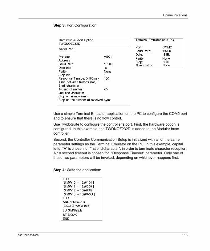
Communications
Step 3: Port Configuration:
Use a simple Terminal Emulator application on the PC to configure the COM2 port and to ensure that there is no flow control.
Use TwidoSuite to configure the controller’s port. First, the hardware option is configured. In this example, the TWDNOZ232D is added to the Modular base controller.
Second, the Controller Communication Setup is initialized with all of the same parameter settings as the Terminal Emulator on the PC. In this example, capital letter "A" is chosen for "1st end character", in order to terminate character reception. A 10 second timeout is chosen for "Response Timeout" parameter. Only one of these two parameters will be invoked, depending on whichever happens first.
Step 4: Write the application:
35011386 05/2009 115
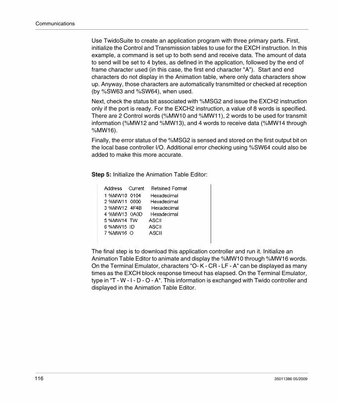
Communications
Use TwidoSuite to create an application program with three primary parts. First, initialize the Control and Transmission tables to use for the EXCH instruction. In this example, a command is set up to both send and receive data. The amount of data to send will be set to 4 bytes, as defined in the application, followed by the end of frame character used (in this case, the first end character "A"). Start and end characters do not display in the Animation table, where only data characters show up. Anyway, those characters are automatically transmitted or checked at reception (by %SW63 and %SW64), when used.
Next, check the status bit associated with %MSG2 and issue the EXCH2 instruction only if the port is ready. For the EXCH2 instruction, a value of 8 words is specified. There are 2 Control words (%MW10 and %MW11), 2 words to be used for transmit information (%MW12 and %MW13), and 4 words to receive data (%MW14 through %MW16).
Finally, the error status of the %MSG2 is sensed and stored on the first output bit on the local base controller I/O. Additional error checking using %SW64 could also be added to make this more accurate.
Step 5: Initialize the Animation Table Editor:
The final step is to download this application controller and run it. Initialize an Animation Table Editor to animate and display the %MW10 through %MW16 words. On the Terminal Emulator, characters "O- K - CR - LF - A" can be displayed as many times as the EXCH block response timeout has elapsed. On the Terminal Emulator, type in "T - W - I - D - O - A". This information is exchanged with Twido controller and displayed in the Animation Table Editor.
116 35011386 05/2009
Communications
Modbus Communications
Introduction
The Modbus protocol is a master-slave protocol that allows for one, and only one, master to request responses from slaves, or to act based on the request. The master can address individual slaves, or can initiate a broadcast message to all slaves. Slaves return a message (response) to queries that are addressed to them individually. Responses are not returned to broadcast queries from the master.
Hardware Configuration
A Modbus link can be established on either the EIA RS232 or EIA RS485 port and can run on as many as two communications ports at a time. Each of these ports can be assigned its own Modbus address, using system bit %S101 and system words %SW101 and %SW102 (see page 719).
The table below lists the devices that can be used:
CAUTIONUNEXPECTED EQUIPMENT OPERATION
Be sure that there is only one Modbus master controller on the bus and that each Modbus slave has a unique address. Failure to observe this precaution may lead to corrupted data or unexpected and ambiguous results.Be sure that all Modbus slaves have unique addresses. No two slaves should have the same address. Failure to observe this precaution may lead to corrupted data or unexpected and ambiguous results.
Failure to follow these instructions can result in injury or equipment damage.
Device Port Specifications
TWDLC•A10/16/24DRF, TWDLC••40DRF, TWDLMDA20/40DTK, TWDLMDA20DRT
1 Base controller supporting a 3-wire EIA RS485 port with a miniDIN connector.
TWDLEDCK1 1 Base controller equipped with non-isolated EIA RS485 type, maximum length limited to 200 m.Note: The following configuration options are not possible
7 bit, no parity, 1 stop bit8 bit, even parity, 2 stop bits8 bit, odd parity, 2 stop bits
35011386 05/2009 117
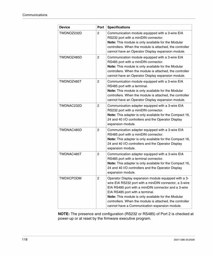
Communications
NOTE: The presence and configuration (RS232 or RS485) of Port 2 is checked at power-up or at reset by the firmware executive program.
TWDNOZ232D 2 Communication module equipped with a 3-wire EIA RS232 port with a miniDIN connector.Note: This module is only available for the Modular controllers. When the module is attached, the controller cannot have an Operator Display expansion module.
TWDNOZ485D 2 Communication module equipped with a 3-wire EIA RS485 port with a miniDIN connector.Note: This module is only available for the Modular controllers. When the module is attached, the controller cannot have an Operator Display expansion module.
TWDNOZ485T 2 Communication module equipped with a 3-wire EIA RS485 port with a terminal.Note: This module is only available for the Modular controllers. When the module is attached, the controller cannot have an Operator Display expansion module.
TWDNAC232D 2 Communication adapter equipped with a 3-wire EIA RS232 port with a miniDIN connector.Note: This adapter is only available for the Compact 16, 24 and 40 I/O controllers and the Operator Display expansion module.
TWDNAC485D 2 Communication adapter equipped with a 3-wire EIA RS485 port with a miniDIN connector.Note: This adapter is only available for the Compact 16, 24 and 40 I/O controllers and the Operator Display expansion module.
TWDNAC485T 2 Communication adapter equipped with a 3-wire EIA RS485 port with a terminal connector.Note: This adapter is only available for the Compact 16, 24 and 40 I/O controllers and the Operator Display expansion module.
TWDXCPODM 2 Operator Display expansion module equipped with a 3-wire EIA RS232 port with a miniDIN connector, a 3-wire EIA RS485 port with a miniDIN connector and a 3-wire EIA RS485 port with a terminal.Note: This module is only available for the Modular controllers. When the module is attached, the controller cannot have a Communication expansion module.
Device Port Specifications
118 35011386 05/2009
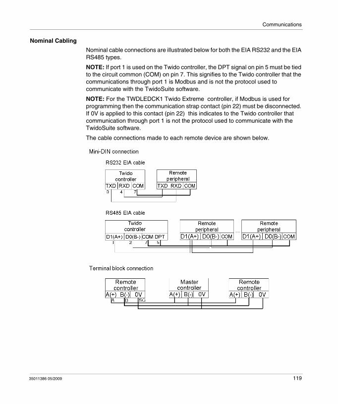
Communications
Nominal Cabling
Nominal cable connections are illustrated below for both the EIA RS232 and the EIA RS485 types.
NOTE: If port 1 is used on the Twido controller, the DPT signal on pin 5 must be tied to the circuit common (COM) on pin 7. This signifies to the Twido controller that the communications through port 1 is Modbus and is not the protocol used to communicate with the TwidoSuite software.
NOTE: For the TWDLEDCK1 Twido Extreme controller, if Modbus is used for programming then the communication strap contact (pin 22) must be disconnected. If 0V is applied to this contact (pin 22) this indicates to the Twido controller that communication through port 1 is not the protocol used to communicate with the TwidoSuite software.
The cable connections made to each remote device are shown below.
35011386 05/2009 119
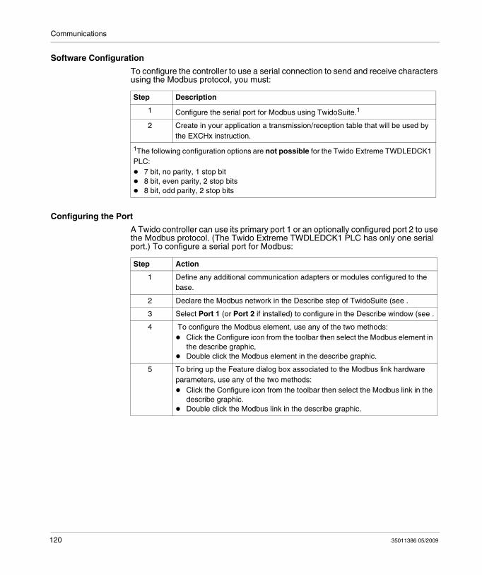
Communications
Software Configuration
To configure the controller to use a serial connection to send and receive characters using the Modbus protocol, you must:
Configuring the Port
A Twido controller can use its primary port 1 or an optionally configured port 2 to use the Modbus protocol. (The Twido Extreme TWDLEDCK1 PLC has only one serial port.) To configure a serial port for Modbus:
Step Description
1 Configure the serial port for Modbus using TwidoSuite.1
2 Create in your application a transmission/reception table that will be used by the EXCHx instruction.
1The following configuration options are not possible for the Twido Extreme TWDLEDCK1 PLC:
7 bit, no parity, 1 stop bit8 bit, even parity, 2 stop bits8 bit, odd parity, 2 stop bits
Step Action
1 Define any additional communication adapters or modules configured to the base.
2 Declare the Modbus network in the Describe step of TwidoSuite (see .
3 Select Port 1 (or Port 2 if installed) to configure in the Describe window (see .
4 To configure the Modbus element, use any of the two methods:Click the Configure icon from the toolbar then select the Modbus element in the describe graphic,Double click the Modbus element in the describe graphic.
5 To bring up the Feature dialog box associated to the Modbus link hardware parameters, use any of the two methods:
Click the Configure icon from the toolbar then select the Modbus link in the describe graphic.Double click the Modbus link in the describe graphic.
120 35011386 05/2009
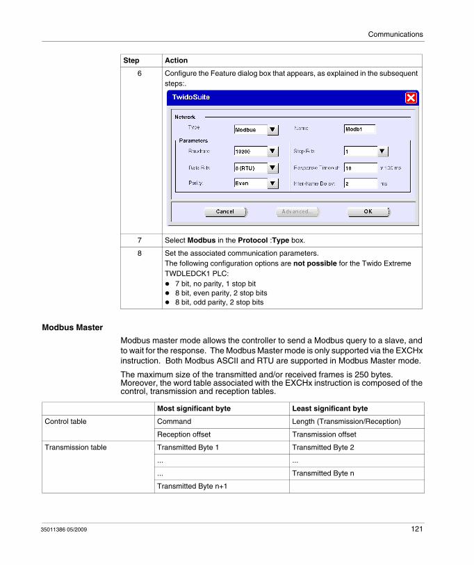
Communications
Modbus Master
Modbus master mode allows the controller to send a Modbus query to a slave, and to wait for the response. The Modbus Master mode is only supported via the EXCHx instruction. Both Modbus ASCII and RTU are supported in Modbus Master mode.
The maximum size of the transmitted and/or received frames is 250 bytes. Moreover, the word table associated with the EXCHx instruction is composed of the control, transmission and reception tables.
6 Configure the Feature dialog box that appears, as explained in the subsequent steps:.
7 Select Modbus in the Protocol :Type box.
8 Set the associated communication parameters.The following configuration options are not possible for the Twido Extreme TWDLEDCK1 PLC:
7 bit, no parity, 1 stop bit8 bit, even parity, 2 stop bits8 bit, odd parity, 2 stop bits
Step Action
Most significant byte Least significant byte
Control table Command Length (Transmission/Reception)
Reception offset Transmission offset
Transmission table Transmitted Byte 1 Transmitted Byte 2
... ...
... Transmitted Byte n
Transmitted Byte n+1
35011386 05/2009 121
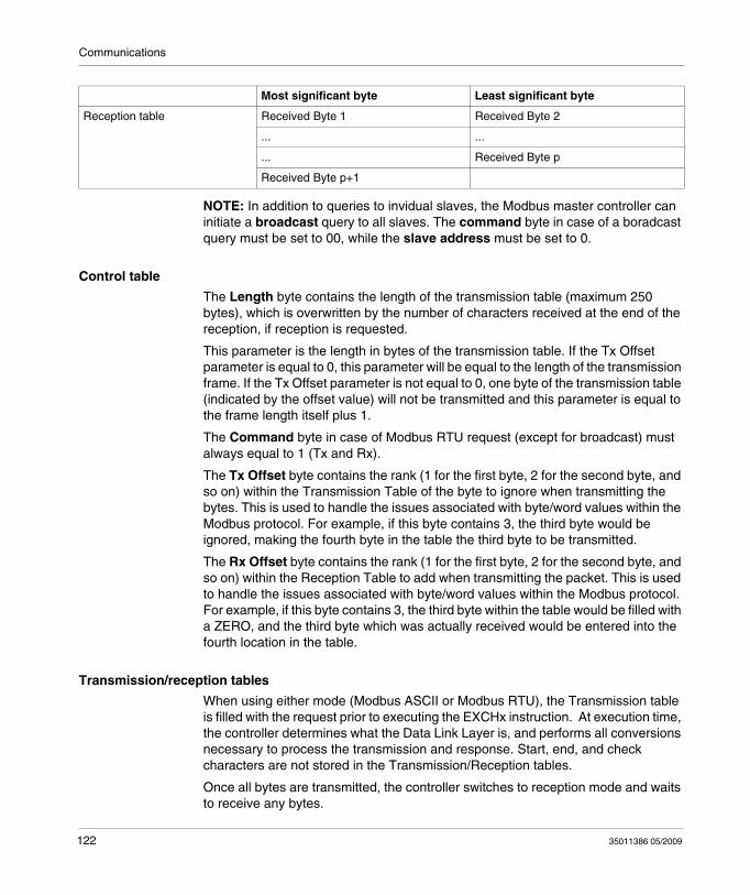
Communications
NOTE: In addition to queries to invidual slaves, the Modbus master controller can initiate a broadcast query to all slaves. The command byte in case of a boradcast query must be set to 00, while the slave address must be set to 0.
Control table
The Length byte contains the length of the transmission table (maximum 250 bytes), which is overwritten by the number of characters received at the end of the reception, if reception is requested.
This parameter is the length in bytes of the transmission table. If the Tx Offset parameter is equal to 0, this parameter will be equal to the length of the transmission frame. If the Tx Offset parameter is not equal to 0, one byte of the transmission table (indicated by the offset value) will not be transmitted and this parameter is equal to the frame length itself plus 1.
The Command byte in case of Modbus RTU request (except for broadcast) must always equal to 1 (Tx and Rx).
The Tx Offset byte contains the rank (1 for the first byte, 2 for the second byte, and so on) within the Transmission Table of the byte to ignore when transmitting the bytes. This is used to handle the issues associated with byte/word values within the Modbus protocol. For example, if this byte contains 3, the third byte would be ignored, making the fourth byte in the table the third byte to be transmitted.
The Rx Offset byte contains the rank (1 for the first byte, 2 for the second byte, and so on) within the Reception Table to add when transmitting the packet. This is used to handle the issues associated with byte/word values within the Modbus protocol. For example, if this byte contains 3, the third byte within the table would be filled with a ZERO, and the third byte which was actually received would be entered into the fourth location in the table.
Transmission/reception tables
When using either mode (Modbus ASCII or Modbus RTU), the Transmission table is filled with the request prior to executing the EXCHx instruction. At execution time, the controller determines what the Data Link Layer is, and performs all conversions necessary to process the transmission and response. Start, end, and check characters are not stored in the Transmission/Reception tables.
Once all bytes are transmitted, the controller switches to reception mode and waits to receive any bytes.
Reception table Received Byte 1 Received Byte 2
... ...
... Received Byte p
Received Byte p+1
Most significant byte Least significant byte
122 35011386 05/2009
Communications
Reception is completed in one of several ways:
timeout on a character or frame has been detected,end of frame character(s) received in ASCII mode,the Reception table is full.
Transmitted byte X entries contain Modbus protocol (RTU encoding) data that is to be transmitted. If the communications port is configured for Modbus ASCII, the correct framing characters are appended to the transmission. The first byte contains the device address (specific or broadcast), the second byte contains the function code, and the rest contain the information associated with that function code.
NOTE: This is a typical application, but does not define all the possibilities. No validation of the data being transmitted will be performed.
Received Bytes X contain Modbus protocol (RTU encoding) data that is to be received. If the communications port is configured for Modbus ASCII, the correct framing characters are removed from the response. The first byte contains the device address, the second byte contains the function code (or response code), and the rest contain the information associated with that function code.
NOTE: This is a typical application, but does not define all the possibilities. No validation of the data being received will be performed, except for checksum verification.
Modbus Slave
Modbus slave mode allows the controller to respond to standard Modbus queries from a Modbus master.
When TSX PCX1031 cable is attached to the controller, TwidoSuite communications are started at the port, temporarily disabling the communications mode that was running prior to the cable being connected.
The Modbus protocol supports two Data Link Layer formats: ASCII and RTU. Each is defined by the Physical Layer implementation, with ASCII using 7 data bits, and RTU using 8 data bits.
When using Modbus ASCII mode, each byte in the message is sent as two ASCII characters. The Modbus ASCII frame begins with a start character (':'), and can end with two end characters (CR and LF). The end of frame character defaults to 0x0A (line feed), and the user can modify the value of this byte during configuration. The check value for the Modbus ASCII frame is a simple two's complement of the frame, excluding the start and end characters.
Modbus RTU mode does not reformat the message prior to transmitting; however, it uses a different checksum calculation mode, specified as a CRC.
The Modbus Data Link Layer has the following limitations:
Address 1-247Bits: 128 bits on requestWords: 125 words of 16 bits on request
35011386 05/2009 123
Communications
Message Exchange
The language offers two services for communication:
EXCHx instruction: to transmit/receive messages%MSGx Function Block: to control the message exchanges.
The Twido controller uses the protocol configured for that port when processing an EXCHx instruction.
NOTE: Each communications port can be configured for different protocols or the same. The EXCHx instruction or %MSGx function block for each communications port is accessed by appending the port number (1 or 2).
EXCHx Instruction
The EXCHx instruction allows the Twido controller to send and/or receive information to/from Modbus devices. The user defines a table of words (%MWi:L) containing control information and the data to be sent and/or received (up to 250 bytes in transmission and/or reception). The format for the word table is described earlier.
A message exchange is performed using the EXCHx instruction:
The Twido controller must finish the exchange from the first EXCHx instruction before a second can be launched. The %MSGx function block must be used when sending several messages.
The processing of the EXCHx list instruction occurs immediately, with any transmissions started under interrupt control (reception of data is also under interrupt control), which is considered background processing.
%MSGx Function Block
The use of the %MSGx function block is optional; it can be used to manage data exchanges. The %MSGx function block has three purposes:
Communications error checkingThe error checking verifies that the parameter L (length of the Word table) programmed with the EXCHx instruction is large enough to contain the length of the message to be sent. This is compared with the length programmed in the least significant byte of the first word of the word table.Coordination of multiple messagesTo ensure the coordination when sending multiple messages, the %MSGx function block provides the information required to determine when transmission of a previous message is complete.
124 35011386 05/2009
Communications
Transmission of priority messagesThe %MSGx function block allows current message transmissions to be stopped in order to allow the immediate sending of an urgent message.
The %MSGx function block has one input and two outputs associated with it:
Limitations
It is important to note the following limitations:
Port 2 presence and configuration (RS232 or RS485) is checked at power-up or resetAny message processing on Port 1 is aborted when the TwidoSuite is connectedEXCHx or %MSG can not be processed on a port configured as Remote LinkEXCHx aborts active Modbus Slave processingProcessing of EXCHx instructions is not re-tried in the event of an errorReset input (R) can be used to abort EXCHx instruction reception processingEXCHx instructions can be configured with a time out to abort receptionMultiple messages are controlled via %MSGx.D
Input/Output Definition Description
R Reset input Set to 1: re-initializes communication or resets block (%MSGx.E = 0 and %MSGx.D = 1).
%MSGx.D Communication complete
0: request in progress.1: communication done if end of transmission, end character received, error, or reset of block.
%MSGx.E Error 0: message length OK and link OK.1: if bad command, table incorrectly configured, incorrect character received (speed, parity, and so on.), or reception table full.
35011386 05/2009 125
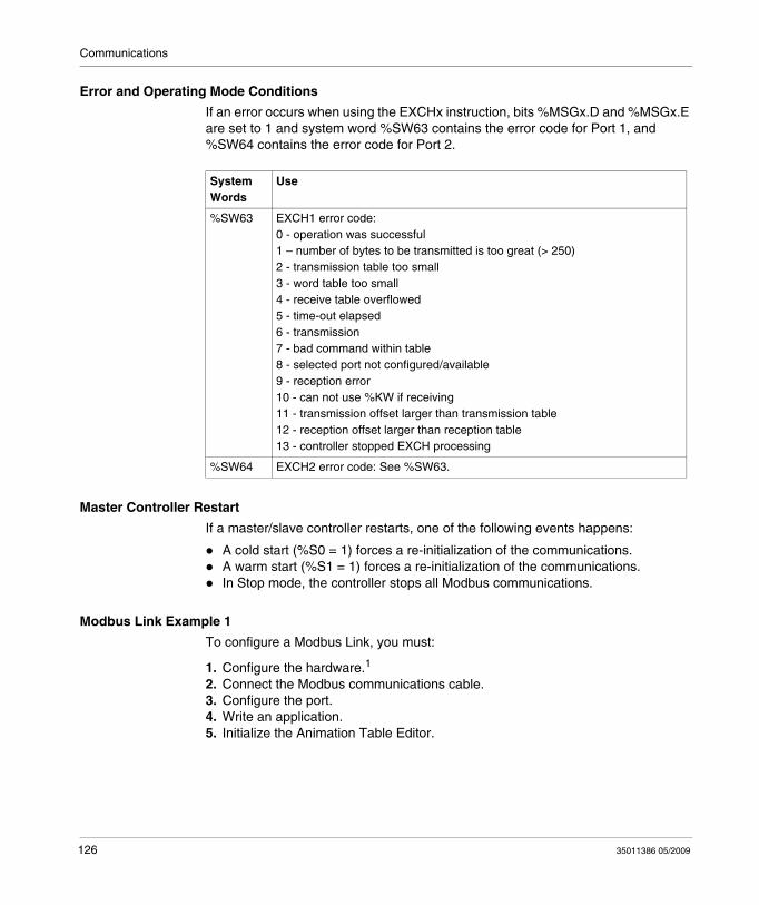
Communications
Error and Operating Mode Conditions
If an error occurs when using the EXCHx instruction, bits %MSGx.D and %MSGx.E are set to 1 and system word %SW63 contains the error code for Port 1, and %SW64 contains the error code for Port 2.
Master Controller Restart
If a master/slave controller restarts, one of the following events happens:
A cold start (%S0 = 1) forces a re-initialization of the communications.A warm start (%S1 = 1) forces a re-initialization of the communications.In Stop mode, the controller stops all Modbus communications.
Modbus Link Example 1
To configure a Modbus Link, you must:
1. Configure the hardware.1
2. Connect the Modbus communications cable.3. Configure the port.4. Write an application.5. Initialize the Animation Table Editor.
System Words
Use
%SW63 EXCH1 error code:0 - operation was successful1 – number of bytes to be transmitted is too great (> 250)2 - transmission table too small3 - word table too small4 - receive table overflowed5 - time-out elapsed6 - transmission7 - bad command within table8 - selected port not configured/available9 - reception error10 - can not use %KW if receiving11 - transmission offset larger than transmission table12 - reception offset larger than reception table13 - controller stopped EXCH processing
%SW64 EXCH2 error code: See %SW63.
126 35011386 05/2009
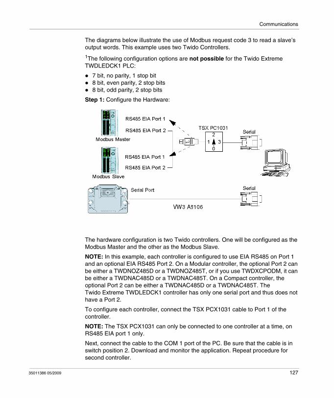
Communications
The diagrams below illustrate the use of Modbus request code 3 to read a slave’s output words. This example uses two Twido Controllers.
1The following configuration options are not possible for the Twido Extreme TWDLEDCK1 PLC:
7 bit, no parity, 1 stop bit8 bit, even parity, 2 stop bits8 bit, odd parity, 2 stop bits
Step 1: Configure the Hardware:
The hardware configuration is two Twido controllers. One will be configured as the Modbus Master and the other as the Modbus Slave.
NOTE: In this example, each controller is configured to use EIA RS485 on Port 1 and an optional EIA RS485 Port 2. On a Modular controller, the optional Port 2 can be either a TWDNOZ485D or a TWDNOZ485T, or if you use TWDXCPODM, it can be either a TWDNAC485D or a TWDNAC485T. On a Compact controller, the optional Port 2 can be either a TWDNAC485D or a TWDNAC485T. The Twido Extreme TWDLEDCK1 controller has only one serial port and thus does not have a Port 2.
To configure each controller, connect the TSX PCX1031 cable to Port 1 of the controller.
NOTE: The TSX PCX1031 can only be connected to one controller at a time, on RS485 EIA port 1 only.
Next, connect the cable to the COM 1 port of the PC. Be sure that the cable is in switch position 2. Download and monitor the application. Repeat procedure for second controller.
35011386 05/2009 127
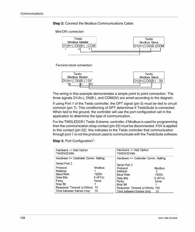
Communications
Step 2: Connect the Modbus Communications Cable:
The wiring in this example demonstrates a simple point to point connection. The three signals D1(A+), D0(B-), and COM(0V) are wired according to the diagram.
If using Port 1 of the Twido controller, the DPT signal (pin 5) must be tied to circuit common (pin 7). This conditioning of DPT determines if TwidoSuite is connected. When tied to the ground, the controller will use the port configuration set in the application to determine the type of communication.
For the TWDLEDCK1 Twido Extreme controller, if Modbus is used for programming then the communication strap contact (pin 22) must be disconnected. If 0V is applied to this contact (pin 22) this indicates to the Twido controller that communication through port 1 is not the protocol used to communicate with the TwidoSuite software.
Step 3: Port Configuration1:
128 35011386 05/2009
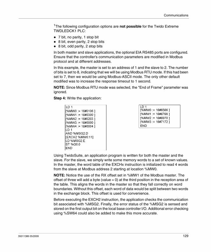
Communications
1The following configuration options are not possible for the Twido Extreme TWDLEDCK1 PLC:
7 bit, no parity, 1 stop bit8 bit, even parity, 2 stop bits8 bit, odd parity, 2 stop bits
In both master and slave applications, the optional EIA RS485 ports are configured. Ensure that the controller's communication parameters are modified in Modbus protocol and at different addresses.
In this example, the master is set to an address of 1 and the slave to 2. The number of bits is set to 8, indicating that we will be using Modbus RTU mode. If this had been set to 7, then we would be using Modbus-ASCII mode. The only other default modified was to increase the response timeout to 1 second.
NOTE: Since Modbus RTU mode was selected, the "End of Frame" parameter was ignored.
Step 4: Write the application:
Using TwidoSuite, an application program is written for both the master and the slave. For the slave, we simply write some memory words to a set of known values. In the master, the word table of the EXCHx instruction is initialized to read 4 words from the slave at Modbus address 2 starting at location %MW0.
NOTE: Notice the use of the RX offset set in %MW1 of the Modbus master. The offset of three will add a byte (value = 0) at the third position in the reception area of the table. This aligns the words in the master so that they fall correctly on word boundaries. Without this offset, each word of data would be split between two words in the exchange block. This offset is used for convenience.
Before executing the EXCH2 instruction, the application checks the communication bit associated with %MSG2. Finally, the error status of the %MSG2 is sensed and stored on the first output bit on the local base controller I/O. Additional error checking using %SW64 could also be added to make this more accurate.
35011386 05/2009 129
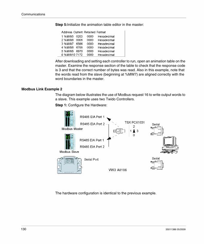
Communications
Step 5:Initialize the animation table editor in the master:
After downloading and setting each controller to run, open an animation table on the master. Examine the response section of the table to check that the response code is 3 and that the correct number of bytes was read. Also in this example, note that the words read from the slave (beginning at %MW7) are aligned correctly with the word boundaries in the master.
Modbus Link Example 2
The diagram below illustrates the use of Modbus request 16 to write output words to a slave. This example uses two Twido Controllers.
Step 1: Configure the Hardware:
The hardware configuration is identical to the previous example.
130 35011386 05/2009
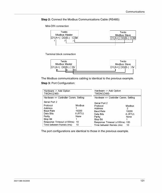
Communications
Step 2: Connect the Modbus Communications Cable (RS485):
The Modbus communications cabling is identical to the previous example.
Step 3: Port Configuration:
The port configurations are identical to those in the previous example.
35011386 05/2009 131
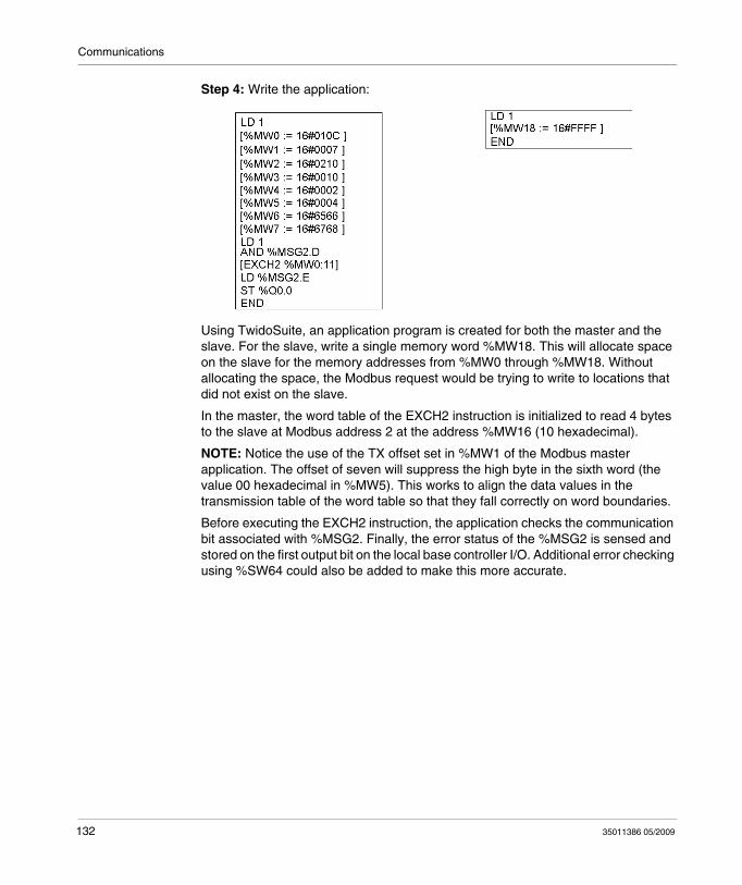
Communications
Step 4: Write the application:
Using TwidoSuite, an application program is created for both the master and the slave. For the slave, write a single memory word %MW18. This will allocate space on the slave for the memory addresses from %MW0 through %MW18. Without allocating the space, the Modbus request would be trying to write to locations that did not exist on the slave.
In the master, the word table of the EXCH2 instruction is initialized to read 4 bytes to the slave at Modbus address 2 at the address %MW16 (10 hexadecimal).
NOTE: Notice the use of the TX offset set in %MW1 of the Modbus master application. The offset of seven will suppress the high byte in the sixth word (the value 00 hexadecimal in %MW5). This works to align the data values in the transmission table of the word table so that they fall correctly on word boundaries.
Before executing the EXCH2 instruction, the application checks the communication bit associated with %MSG2. Finally, the error status of the %MSG2 is sensed and stored on the first output bit on the local base controller I/O. Additional error checking using %SW64 could also be added to make this more accurate.
132 35011386 05/2009
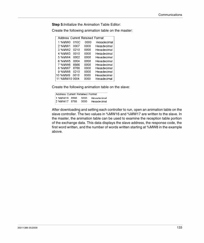
Communications
Step 5:Initialize the Animation Table Editor:
Create the following animation table on the master:
Create the following animation table on the slave:
After downloading and setting each controller to run, open an animation table on the slave controller. The two values in %MW16 and %MW17 are written to the slave. In the master, the animation table can be used to examine the reception table portion of the exchange data. This data displays the slave address, the response code, the first word written, and the number of words written starting at %MW8 in the example above.
35011386 05/2009 133
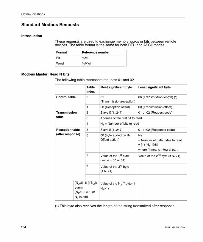
Communications
Standard Modbus Requests
Introduction
These requests are used to exchange memory words or bits between remote devices. The table format is the same for both RTU and ASCII modes.
Modbus Master: Read N Bits
The following table represents requests 01 and 02.
(*) This byte also receives the length of the string transmitted after response
Format Reference number
Bit %Mi
Word %MWi
TableIndex
Most significant byte Least significant byte
Control table 0 01 (Transmission/reception)
06 (Transmission length) (*)
1 03 (Reception offset) 00 (Transmission offset)
Transmission table
2 Slave@(1..247) 01 or 02 (Request code)
3 Address of the first bit to read
4 N1 = Number of bits to read
Reception table (after response)
5 Slave@(1..247) 01 or 02 (Response code)
6 00 (byte added by Rx Offset action)
N2
= Number of data bytes to read= [1+(N1-1)/8],
where [] means integral part
7 Value of the 1st byte (value = 00 or 01)
Value of the 2nd byte (if N1>1)
8 Value of the 3rd byte (if N1>1)
...
(N2/2)+6 (if N2 is
even)(N2/2+1)+6 (if
N2 is odd
Value of the N2 th byte (if
N1>1)
134 35011386 05/2009
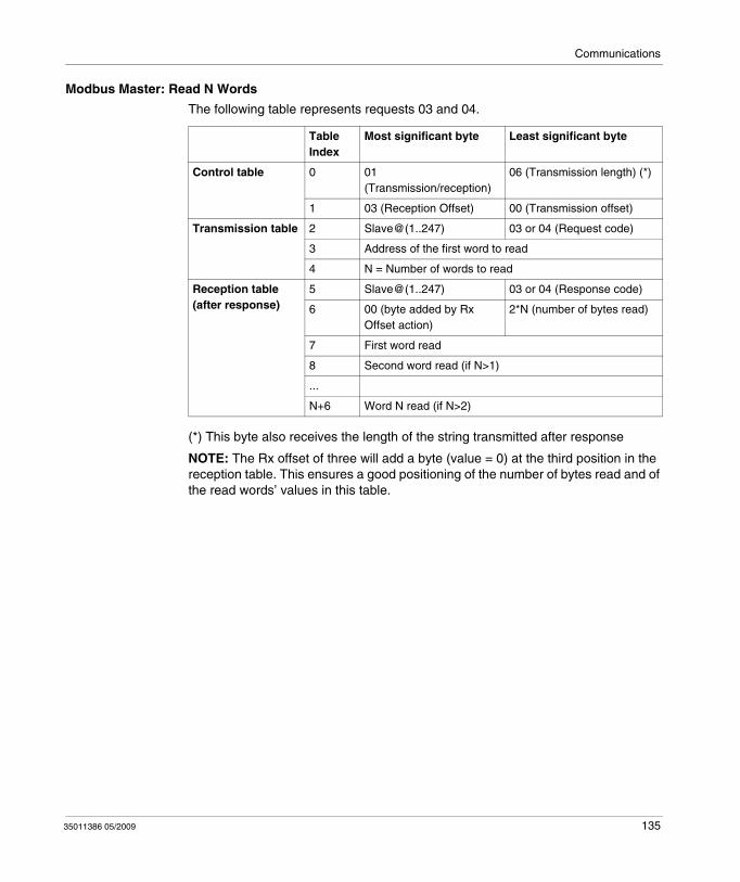
Communications
Modbus Master: Read N Words
The following table represents requests 03 and 04.
(*) This byte also receives the length of the string transmitted after response
NOTE: The Rx offset of three will add a byte (value = 0) at the third position in the reception table. This ensures a good positioning of the number of bytes read and of the read words’ values in this table.
TableIndex
Most significant byte Least significant byte
Control table 0 01 (Transmission/reception)
06 (Transmission length) (*)
1 03 (Reception Offset) 00 (Transmission offset)
Transmission table 2 Slave@(1..247) 03 or 04 (Request code)
3 Address of the first word to read
4 N = Number of words to read
Reception table (after response)
5 Slave@(1..247) 03 or 04 (Response code)
6 00 (byte added by Rx Offset action)
2*N (number of bytes read)
7 First word read
8 Second word read (if N>1)
...
N+6 Word N read (if N>2)
35011386 05/2009 135
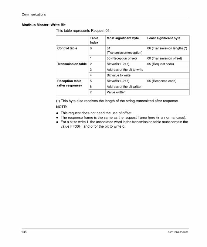
Communications
Modbus Master: Write Bit
This table represents Request 05.
(*) This byte also receives the length of the string transmitted after response
NOTE:
This request does not need the use of offset.The response frame is the same as the request frame here (in a normal case).For a bit to write 1, the associated word in the transmission table must contain the value FF00H, and 0 for the bit to write 0.
TableIndex
Most significant byte Least significant byte
Control table 0 01 (Transmission/reception)
06 (Transmission length) (*)
1 00 (Reception offset) 00 (Transmission offset)
Transmission table 2 Slave@(1..247) 05 (Request code)
3 Address of the bit to write
4 Bit value to write
Reception table (after response)
5 Slave@(1..247) 05 (Response code)
6 Address of the bit written
7 Value written
136 35011386 05/2009
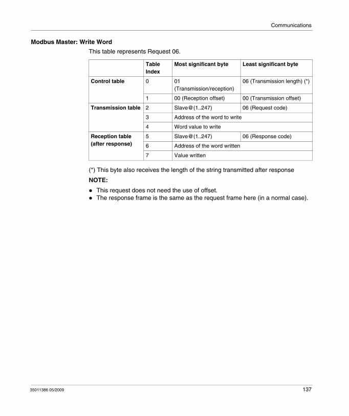
Communications
Modbus Master: Write Word
This table represents Request 06.
(*) This byte also receives the length of the string transmitted after response
NOTE:
This request does not need the use of offset.The response frame is the same as the request frame here (in a normal case).
TableIndex
Most significant byte Least significant byte
Control table 0 01 (Transmission/reception)
06 (Transmission length) (*)
1 00 (Reception offset) 00 (Transmission offset)
Transmission table 2 Slave@(1..247) 06 (Request code)
3 Address of the word to write
4 Word value to write
Reception table (after response)
5 Slave@(1..247) 06 (Response code)
6 Address of the word written
7 Value written
35011386 05/2009 137
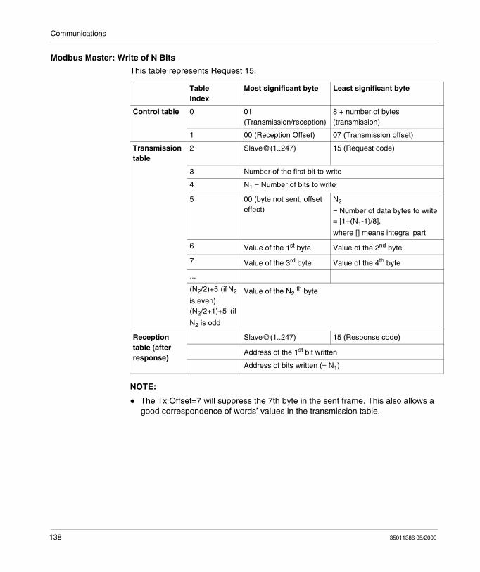
Communications
Modbus Master: Write of N Bits
This table represents Request 15.
NOTE:
The Tx Offset=7 will suppress the 7th byte in the sent frame. This also allows a good correspondence of words’ values in the transmission table.
TableIndex
Most significant byte Least significant byte
Control table 0 01 (Transmission/reception)
8 + number of bytes (transmission)
1 00 (Reception Offset) 07 (Transmission offset)
Transmission table
2 Slave@(1..247) 15 (Request code)
3 Number of the first bit to write
4 N1 = Number of bits to write
5 00 (byte not sent, offset effect)
N2
= Number of data bytes to write= [1+(N1-1)/8],
where [] means integral part
6 Value of the 1st byte Value of the 2nd byte
7 Value of the 3rd byte Value of the 4th byte
...
(N2/2)+5 (if N2
is even)(N2/2+1)+5 (if
N2 is odd
Value of the N2 th byte
Reception table (after response)
Slave@(1..247) 15 (Response code)
Address of the 1st bit written
Address of bits written (= N1)
138 35011386 05/2009
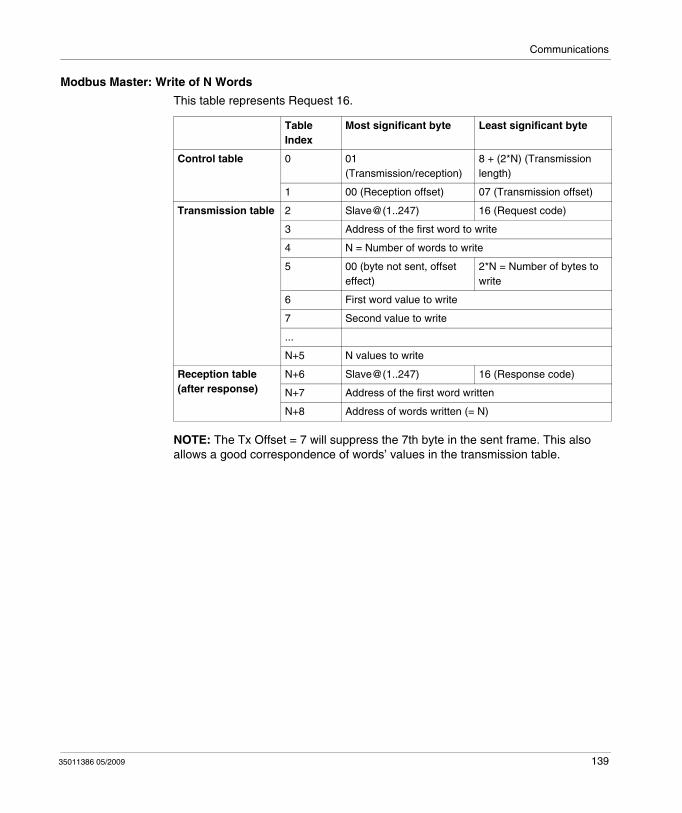
Communications
Modbus Master: Write of N Words
This table represents Request 16.
NOTE: The Tx Offset = 7 will suppress the 7th byte in the sent frame. This also allows a good correspondence of words’ values in the transmission table.
TableIndex
Most significant byte Least significant byte
Control table 0 01 (Transmission/reception)
8 + (2*N) (Transmission length)
1 00 (Reception offset) 07 (Transmission offset)
Transmission table 2 Slave@(1..247) 16 (Request code)
3 Address of the first word to write
4 N = Number of words to write
5 00 (byte not sent, offset effect)
2*N = Number of bytes to write
6 First word value to write
7 Second value to write
...
N+5 N values to write
Reception table (after response)
N+6 Slave@(1..247) 16 (Response code)
N+7 Address of the first word written
N+8 Address of words written (= N)
35011386 05/2009 139

Communications
Modbus Function Codes 23 (MB FC) - Read/Write Multiple registers and N Words
Description
The Read/Write Multiple Registers function code performs a combination of one read operation and one write operation in a single Modbus transaction.
NOTE: The write operation is performed before the read operation.
Holding registers are addressed starting at zero. Therefore, holding registers 1 to 16 are addressed in the PDU as 0 to 15.
Request Parameters
The request specifies the starting address and the number of holding registers to be read as well as the starting address, the number of holding registers and the data to be written.
The byte count specifies the number of bytes that will be written in the write date field.
The following tables gives the Read/Write Multiple Registers request parameter values:
N* is the quantity to write.
Parameter Number of Bytes Values
Function code 1 Byte 0x17
Read Starting Address 2 Bytes 0x0000 to 0xFFFF
Quantity to Read 2 Bytes 0x0000 to approx. 0x0076
Write Starting Address 2 Bytes 0x0000 to 0xFFFF
Quantity to Write 2 Bytes 0x0000 to approx. 0x0076
Write Byte Count 1 Byte N* x 2
Write Registers Value N* x 2 Bytes
140 35011386 05/2009
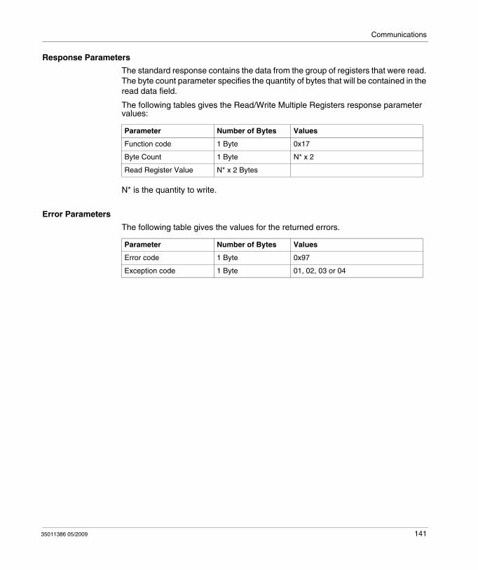
Communications
Response Parameters
The standard response contains the data from the group of registers that were read. The byte count parameter specifies the quantity of bytes that will be contained in the read data field.
The following tables gives the Read/Write Multiple Registers response parameter values:
N* is the quantity to write.
Error Parameters
The following table gives the values for the returned errors.
Parameter Number of Bytes Values
Function code 1 Byte 0x17
Byte Count 1 Byte N* x 2
Read Register Value N* x 2 Bytes
Parameter Number of Bytes Values
Error code 1 Byte 0x97
Exception code 1 Byte 01, 02, 03 or 04
35011386 05/2009 141
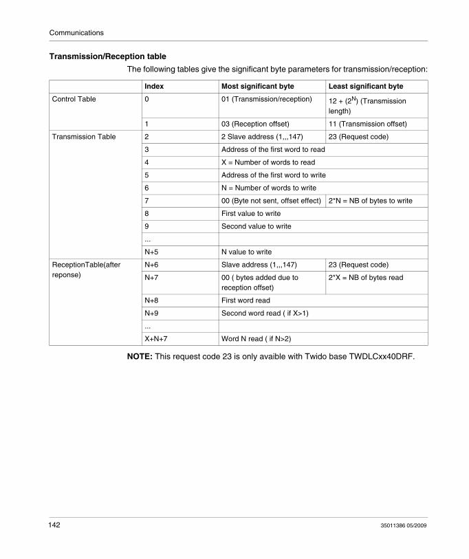
Communications
Transmission/Reception table
The following tables give the significant byte parameters for transmission/reception:
NOTE: This request code 23 is only avaible with Twido base TWDLCxx40DRF.
Index Most significant byte Least significant byte
Control Table 0 01 (Transmission/reception) 12 + (2N) (Transmission length)
1 03 (Reception offset) 11 (Transmission offset)
Transmission Table 2 2 Slave address (1,,,147) 23 (Request code)
3 Address of the first word to read
4 X = Number of words to read
5 Address of the first word to write
6 N = Number of words to write
7 00 (Byte not sent, offset effect) 2*N = NB of bytes to write
8 First value to write
9 Second value to write
...
N+5 N value to write
ReceptionTable(after reponse)
N+6 Slave address (1,,,147) 23 (Request code)
N+7 00 ( bytes added due to reception offset)
2*X = NB of bytes read
N+8 First word read
N+9 Second word read ( if X>1)
...
X+N+7 Word N read ( if N>2)
142 35011386 05/2009
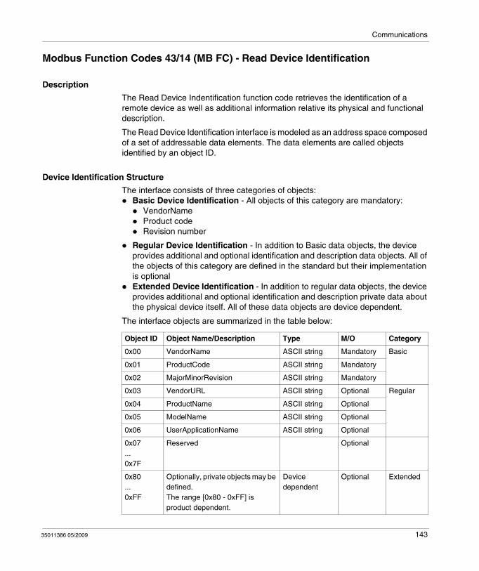
Communications
Modbus Function Codes 43/14 (MB FC) - Read Device Identification
Description
The Read Device Indentification function code retrieves the identification of a remote device as well as additional information relative its physical and functional description.
The Read Device Identification interface is modeled as an address space composed of a set of addressable data elements. The data elements are called objects identified by an object ID.
Device Identification Structure
The interface consists of three categories of objects:Basic Device Identification - All objects of this category are mandatory:
VendorNameProduct codeRevision number
Regular Device Identification - In addition to Basic data objects, the device provides additional and optional identification and description data objects. All of the objects of this category are defined in the standard but their implementation is optionalExtended Device Identification - In addition to regular data objects, the device provides additional and optional identification and description private data about the physical device itself. All of these data objects are device dependent.
The interface objects are summarized in the table below:
Object ID Object Name/Description Type M/O Category
0x00 VendorName ASCII string Mandatory Basic
0x01 ProductCode ASCII string Mandatory
0x02 MajorMinorRevision ASCII string Mandatory
0x03 VendorURL ASCII string Optional Regular
0x04 ProductName ASCII string Optional
0x05 ModelName ASCII string Optional
0x06 UserApplicationName ASCII string Optional
0x07...0x7F
Reserved Optional
0x80...0xFF
Optionally, private objects may be defined.The range [0x80 - 0xFF] is product dependent.
Device dependent
Optional Extended
35011386 05/2009 143
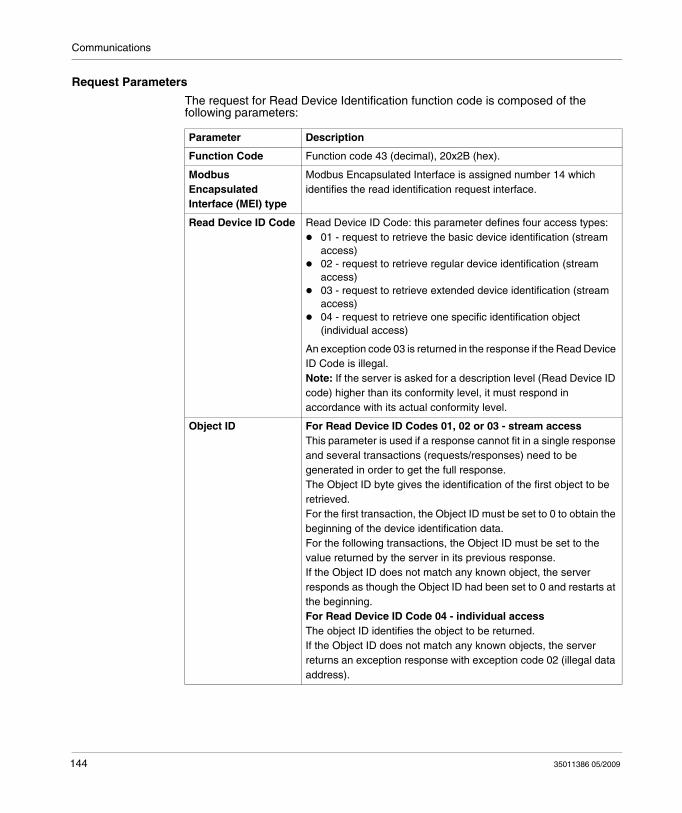
Communications
Request Parameters
The request for Read Device Identification function code is composed of the following parameters:
Parameter Description
Function Code Function code 43 (decimal), 20x2B (hex).
Modbus Encapsulated Interface (MEI) type
Modbus Encapsulated Interface is assigned number 14 which identifies the read identification request interface.
Read Device ID Code Read Device ID Code: this parameter defines four access types:01 - request to retrieve the basic device identification (stream access) 02 - request to retrieve regular device identification (stream access)03 - request to retrieve extended device identification (stream access)04 - request to retrieve one specific identification object (individual access)
An exception code 03 is returned in the response if the Read Device ID Code is illegal.Note: If the server is asked for a description level (Read Device ID code) higher than its conformity level, it must respond in accordance with its actual conformity level.
Object ID For Read Device ID Codes 01, 02 or 03 - stream access This parameter is used if a response cannot fit in a single response and several transactions (requests/responses) need to be generated in order to get the full response. The Object ID byte gives the identification of the first object to be retrieved.For the first transaction, the Object ID must be set to 0 to obtain the beginning of the device identification data.For the following transactions, the Object ID must be set to the value returned by the server in its previous response. If the Object ID does not match any known object, the server responds as though the Object ID had been set to 0 and restarts at the beginning.For Read Device ID Code 04 - individual access The object ID identifies the object to be returned.If the Object ID does not match any known objects, the server returns an exception response with exception code 02 (illegal data address).
144 35011386 05/2009
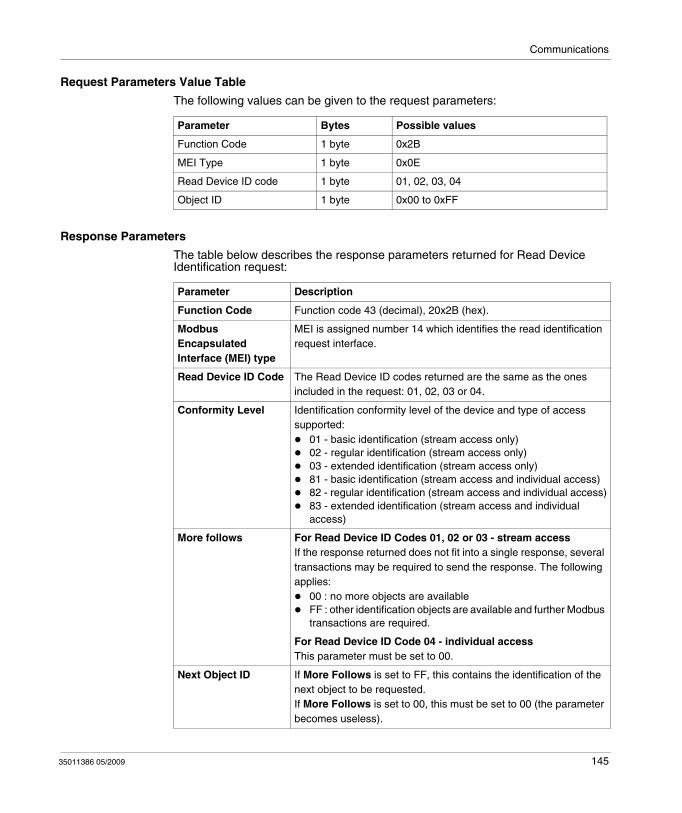
Communications
Request Parameters Value Table
The following values can be given to the request parameters:
Response Parameters
The table below describes the response parameters returned for Read Device Identification request:
Parameter Bytes Possible values
Function Code 1 byte 0x2B
MEI Type 1 byte 0x0E
Read Device ID code 1 byte 01, 02, 03, 04
Object ID 1 byte 0x00 to 0xFF
Parameter Description
Function Code Function code 43 (decimal), 20x2B (hex).
Modbus Encapsulated Interface (MEI) type
MEI is assigned number 14 which identifies the read identification request interface.
Read Device ID Code The Read Device ID codes returned are the same as the ones included in the request: 01, 02, 03 or 04.
Conformity Level Identification conformity level of the device and type of access supported:
01 - basic identification (stream access only)02 - regular identification (stream access only)03 - extended identification (stream access only)81 - basic identification (stream access and individual access)82 - regular identification (stream access and individual access)83 - extended identification (stream access and individual access)
More follows For Read Device ID Codes 01, 02 or 03 - stream access If the response returned does not fit into a single response, several transactions may be required to send the response. The following applies:
00 : no more objects are availableFF : other identification objects are available and further Modbus transactions are required.
For Read Device ID Code 04 - individual access This parameter must be set to 00.
Next Object ID If More Follows is set to FF, this contains the identification of the next object to be requested. If More Follows is set to 00, this must be set to 00 (the parameter becomes useless).
35011386 05/2009 145
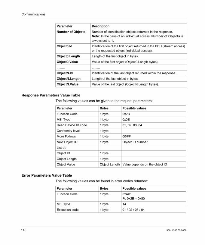
Communications
Response Parameters Value Table
The following values can be given to the request parameters:
Error Parameters Value Table
The following values can be found in error codes returned:
Number of Objects Number of identification objects returned in the response.Note: In the case of an individual access, Number of Objects is always set to 1.
Object0.Id Identification of the first object returned in the PDU (stream access) or the requested object (individual access).
Object0.Length Length of the first object in bytes.
Object0.Value Value of the first object (Object0.Length bytes).
......... .........
ObjectN.Id Identification of the last object returned within the response.
ObjectN.Length Length of the last object in bytes.
ObjectN.Value Value of the last object (ObjectN.Length bytes).
Parameter Description
Parameter Bytes Possible values
Function Code 1 byte 0x2B
MEI Type 1 byte 0x0E
Read Device ID code 1 byte 01, 02, 03, 04
Conformity level 1 byte
More Follows 1 byte 00/FF
Next Object ID 1 byte Object ID number
List of:
Object ID 1 byte
Object Length 1 byte
Object Value Object Length Value depends on the object ID
Parameter Bytes Possible values
Function Code 1 byte 0xAB:Fc 0x2B + 0x80
MEI Type 1 byte 14
Exception code 1 byte 01 / 02 / 03 / 04
146 35011386 05/2009
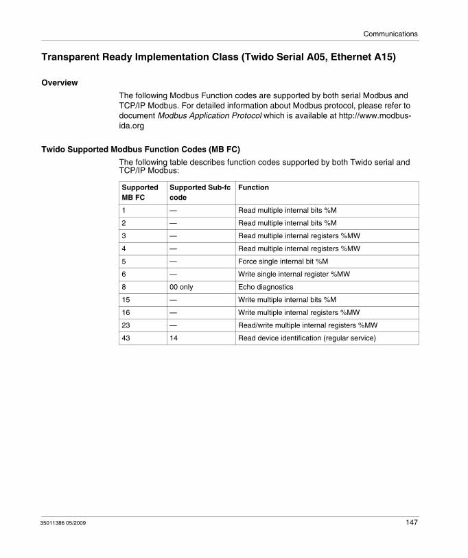
Communications
Transparent Ready Implementation Class (Twido Serial A05, Ethernet A15)
Overview
The following Modbus Function codes are supported by both serial Modbus and TCP/IP Modbus. For detailed information about Modbus protocol, please refer to document Modbus Application Protocol which is available at http://www.modbus-ida.org
Twido Supported Modbus Function Codes (MB FC)
The following table describes function codes supported by both Twido serial and TCP/IP Modbus:
Supported MB FC
Supported Sub-fc code
Function
1 — Read multiple internal bits %M
2 — Read multiple internal bits %M
3 — Read multiple internal registers %MW
4 — Read multiple internal registers %MW
5 — Force single internal bit %M
6 — Write single internal register %MW
8 00 only Echo diagnostics
15 — Write multiple internal bits %M
16 — Write multiple internal registers %MW
23 — Read/write multiple internal registers %MW
43 14 Read device identification (regular service)
35011386 05/2009 147

Communications
148 35011386 05/2009
35011386 05/2009
6
Built-In Analog Functions
35011386 05/2009
Built-In Analog Functions
Subject of this Chapter
This chapter describes how to manage the built-in analog channel and potentiometers.
What's in this Chapter?
This chapter contains the following topics:
Topic Page
Analog potentiometer 150
Analog Channel 152
149
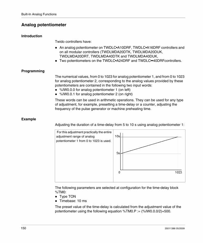
Built-In Analog Functions
Analog potentiometer
Introduction
Twido controllers have:
An analog potentiometer on TWDLC•A10DRF, TWDLC•A16DRF controllers and on all modular controllers (TWDLMDA20DTK, TWDLMDA20DUK, TWDLMDA20DRT, TWDLMDA40DTK and TWDLMDA40DUK,Two potentiometers on the TWDLC•A24DRF and TWDLC••40DRFcontrollers.
Programming
The numerical values, from 0 to 1023 for analog potentiometer 1, and from 0 to 1023 for analog potentiometer 2, corresponding to the analog values provided by these potentiometers are contained in the following two input words:
%IW0.0.0 for analog potentiometer 1 (on left)%IW0.0.1 for analog potentiometer 2 (on right)
These words can be used in arithmetic operations. They can be used for any type of adjustment, for example, presetting a time-delay or a counter, adjusting the frequency of the pulse generator or machine preheating time.
Example
Adjusting the duration of a time-delay from 5 to 10 s using analog potentiometer 1:
The following parameters are selected at configuration for the time-delay block %TM0:
Type TONTimebase: 10 ms
The preset value of the time-delay is calculated from the adjustment value of the potentiometer using the following equation %TM0.P := (%IW0.0.0/2)+500.
For this adjustment practically the entire adjustment range of analog potentiometer 1 from 0 to 1023 is used.
150 35011386 05/2009
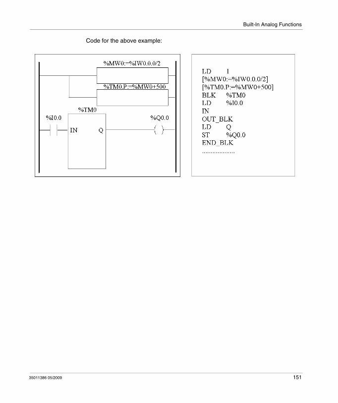
Built-In Analog Functions
Code for the above example:
35011386 05/2009 151
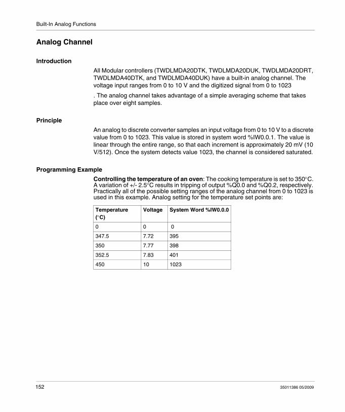
Built-In Analog Functions
Analog Channel
Introduction
All Modular controllers (TWDLMDA20DTK, TWDLMDA20DUK, TWDLMDA20DRT, TWDLMDA40DTK, and TWDLMDA40DUK) have a built-in analog channel. The voltage input ranges from 0 to 10 V and the digitized signal from 0 to 1023
. The analog channel takes advantage of a simple averaging scheme that takes place over eight samples.
Principle
An analog to discrete converter samples an input voltage from 0 to 10 V to a discrete value from 0 to 1023. This value is stored in system word %IW0.0.1. The value is linear through the entire range, so that each increment is approximately 20 mV (10 V/512). Once the system detects value 1023, the channel is considered saturated.
Programming Example
Controlling the temperature of an oven: The cooking temperature is set to 350°C. A variation of +/- 2.5°C results in tripping of output %Q0.0 and %Q0.2, respectively. Practically all of the possible setting ranges of the analog channel from 0 to 1023 is used in this example. Analog setting for the temperature set points are:
Temperature (°C)
Voltage System Word %IW0.0.0
0 0 0
347.5 7.72 395
350 7.77 398
352.5 7.83 401
450 10 1023
152 35011386 05/2009
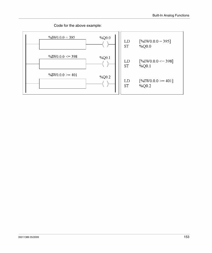
Built-In Analog Functions
Code for the above example:
35011386 05/2009 153

Built-In Analog Functions
154 35011386 05/2009
35011386 05/2009
7
Managing Analog Modules
35011386 05/2009
Managing Analog Modules
Subject of this Chapter
This chapter provides an overview of managing analog modules for Twido controllers.
What's in this Chapter?
This chapter contains the following topics:
Topic Page
Analog Module Overview 156
Addressing Analog Inputs and Outputs 157
Configuring Analog Inputs and Outputs 159
Analog Module Status Information 166
Example of Using Analog Modules 168
155
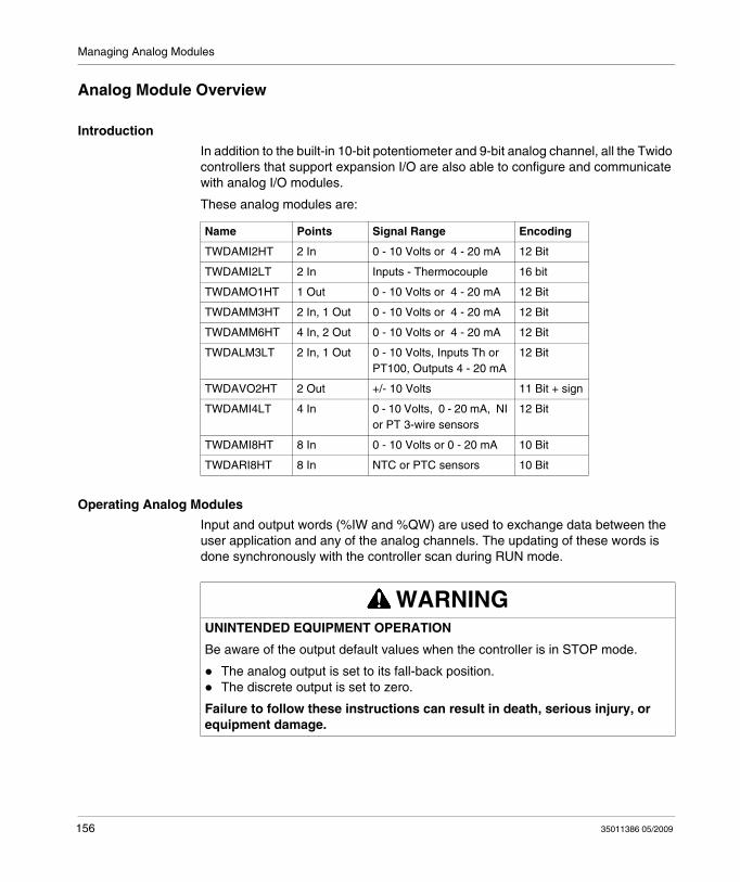
Managing Analog Modules
Analog Module Overview
Introduction
In addition to the built-in 10-bit potentiometer and 9-bit analog channel, all the Twido controllers that support expansion I/O are also able to configure and communicate with analog I/O modules.
These analog modules are:
Operating Analog Modules
Input and output words (%IW and %QW) are used to exchange data between the user application and any of the analog channels. The updating of these words is done synchronously with the controller scan during RUN mode.
Name Points Signal Range Encoding
TWDAMI2HT 2 In 0 - 10 Volts or 4 - 20 mA 12 Bit
TWDAMI2LT 2 In Inputs - Thermocouple 16 bit
TWDAMO1HT 1 Out 0 - 10 Volts or 4 - 20 mA 12 Bit
TWDAMM3HT 2 In, 1 Out 0 - 10 Volts or 4 - 20 mA 12 Bit
TWDAMM6HT 4 In, 2 Out 0 - 10 Volts or 4 - 20 mA 12 Bit
TWDALM3LT 2 In, 1 Out 0 - 10 Volts, Inputs Th or PT100, Outputs 4 - 20 mA
12 Bit
TWDAVO2HT 2 Out +/- 10 Volts 11 Bit + sign
TWDAMI4LT 4 In 0 - 10 Volts, 0 - 20 mA, NI or PT 3-wire sensors
12 Bit
TWDAMI8HT 8 In 0 - 10 Volts or 0 - 20 mA 10 Bit
TWDARI8HT 8 In NTC or PTC sensors 10 Bit
WARNINGUNINTENDED EQUIPMENT OPERATION
Be aware of the output default values when the controller is in STOP mode.
The analog output is set to its fall-back position.The discrete output is set to zero.
Failure to follow these instructions can result in death, serious injury, or equipment damage.
156 35011386 05/2009
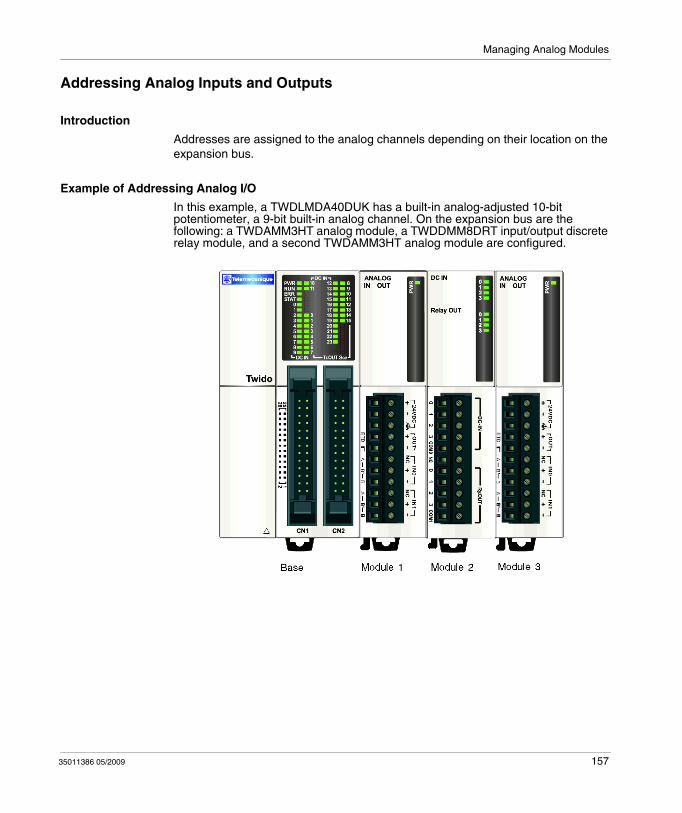
Managing Analog Modules
Addressing Analog Inputs and Outputs
Introduction
Addresses are assigned to the analog channels depending on their location on the expansion bus.
Example of Addressing Analog I/O
In this example, a TWDLMDA40DUK has a built-in analog-adjusted 10-bit potentiometer, a 9-bit built-in analog channel. On the expansion bus are the following: a TWDAMM3HT analog module, a TWDDMM8DRT input/output discrete relay module, and a second TWDAMM3HT analog module are configured.
35011386 05/2009 157
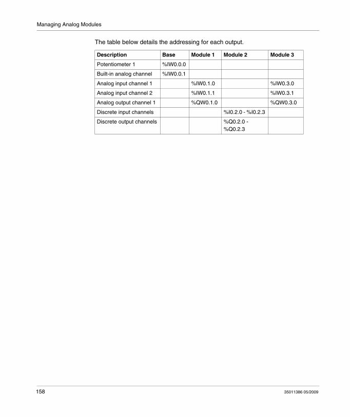
Managing Analog Modules
The table below details the addressing for each output.
Description Base Module 1 Module 2 Module 3
Potentiometer 1 %IW0.0.0
Built-in analog channel %IW0.0.1
Analog input channel 1 %IW0.1.0 %IW0.3.0
Analog input channel 2 %IW0.1.1 %IW0.3.1
Analog output channel 1 %QW0.1.0 %QW0.3.0
Discrete input channels %I0.2.0 - %I0.2.3
Discrete output channels %Q0.2.0 -%Q0.2.3
158 35011386 05/2009
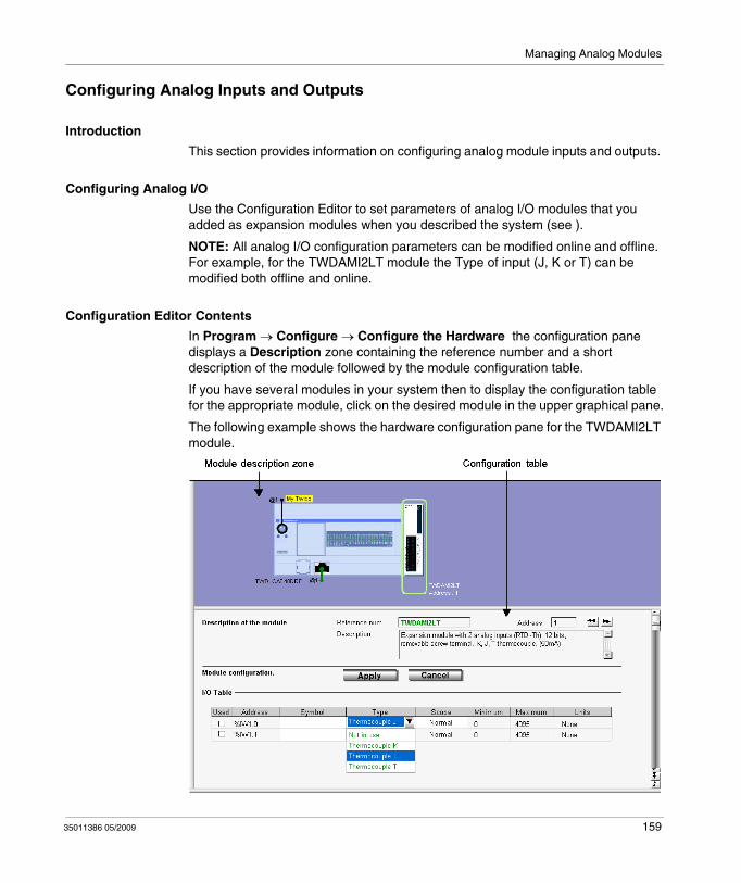
Managing Analog Modules
Configuring Analog Inputs and Outputs
Introduction
This section provides information on configuring analog module inputs and outputs.
Configuring Analog I/O
Use the Configuration Editor to set parameters of analog I/O modules that you added as expansion modules when you described the system (see ).
NOTE: All analog I/O configuration parameters can be modified online and offline. For example, for the TWDAMI2LT module the Type of input (J, K or T) can be modified both offline and online.
Configuration Editor Contents
In Program → Configure → Configure the Hardware the configuration pane displays a Description zone containing the reference number and a short description of the module followed by the module configuration table.
If you have several modules in your system then to display the configuration table for the appropriate module, click on the desired module in the upper graphical pane.
The following example shows the hardware configuration pane for the TWDAMI2LT module.
35011386 05/2009 159
Managing Analog Modules
The table shows: Address, Symbol, Type, Range, Minimum, Maximum and Units
In TWDAMI4LT and TWIDAMI8HT, the table is preceded by an Input type list box.In TWDAVO2HT and TWDAMI8HT, the Type column is replaced by a Configured column with check boxes.In TWDARI8HT, each channel (0-7) is configured individually within a tab, in which you can choose either the Chart or Formula configuration method. The table can be seen in a Recap tab.
Description
The Description zone displays a short summary of the module.
Address
Each row of the spreadsheet represents either an input or output channel of the module.
The addresses of each of these are identified in the following table, where "i" is the location of the module on the expansion bus.
Symbol
This is a read-only display of a symbol, if assigned, for the address.
Input and Output Type
This identifies the mode of a channel. The choices depend on the channel and type of module.
Module Name Address
TWDAMI2LT 2 Inputs (%IWi.0, %IWi.1)
TWDALM3LT 2 Inputs (%IWi.0, %IWi.1), 1 Output (%QWi.0)
TWDAMM3HT 2 Inputs (%IWi.0, %IWi.1), 1 Output (%QWi.0)
TWDAMM6HT 4 Inputs (%IWi.0 to %IWi.3), 2 Outputs (%QWi.0, %QWi.1)
TWDAMI2HT 2 Inputs (%IWi.0, %IWi.1)
TWDAMO1HT 1 Output (%QWi.0)
TWDAVO2HT 2 Outputs (%QWi.0, %QWi.1)
TWDAMI4LT 4 Inputs (%IWi.0 to %IWi.3)
TWDAMI8HT 8 Inputs (%IWi.0 to %IWi.7)
TWDARI8HT 8 Inputs (%IWi.0 to %IWi.7)
160 35011386 05/2009
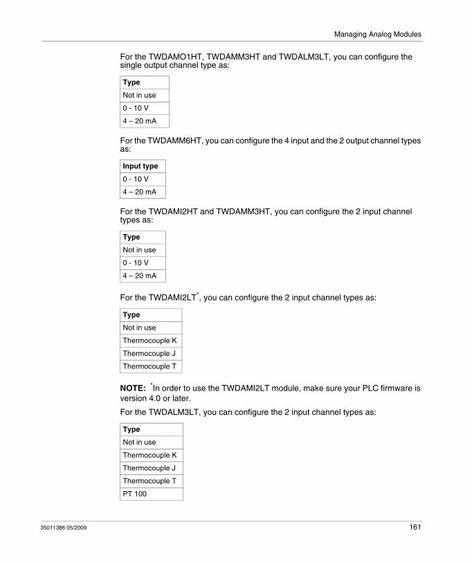
Managing Analog Modules
For the TWDAMO1HT, TWDAMM3HT and TWDALM3LT, you can configure the single output channel type as:
For the TWDAMM6HT, you can configure the 4 input and the 2 output channel types as:
For the TWDAMI2HT and TWDAMM3HT, you can configure the 2 input channel types as:
For the TWDAMI2LT*, you can configure the 2 input channel types as:
NOTE: *In order to use the TWDAMI2LT module, make sure your PLC firmware is version 4.0 or later.
For the TWDALM3LT, you can configure the 2 input channel types as:
Type
Not in use
0 - 10 V
4 – 20 mA
Input type
0 - 10 V
4 – 20 mA
Type
Not in use
0 - 10 V
4 – 20 mA
Type
Not in use
Thermocouple K
Thermocouple J
Thermocouple T
Type
Not in use
Thermocouple K
Thermocouple J
Thermocouple T
PT 100
35011386 05/2009 161
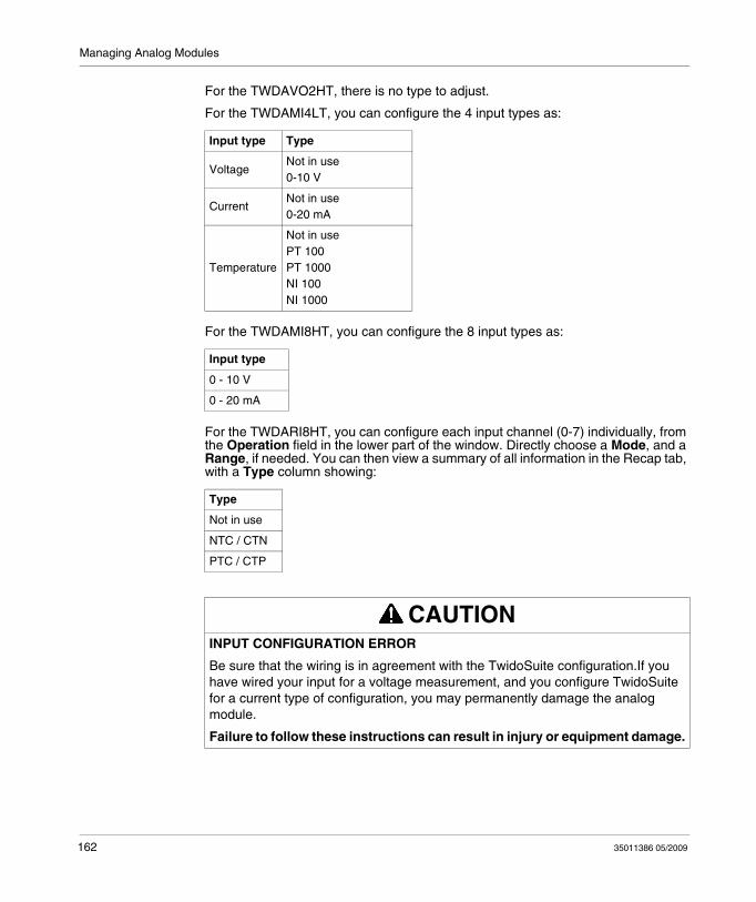
Managing Analog Modules
For the TWDAVO2HT, there is no type to adjust.
For the TWDAMI4LT, you can configure the 4 input types as:
For the TWDAMI8HT, you can configure the 8 input types as:
For the TWDARI8HT, you can configure each input channel (0-7) individually, from the Operation field in the lower part of the window. Directly choose a Mode, and a Range, if needed. You can then view a summary of all information in the Recap tab, with a Type column showing:
Input type Type
VoltageNot in use0-10 V
CurrentNot in use0-20 mA
Temperature
Not in usePT 100PT 1000NI 100NI 1000
Input type
0 - 10 V
0 - 20 mA
Type
Not in use
NTC / CTN
PTC / CTP
CAUTIONINPUT CONFIGURATION ERROR
Be sure that the wiring is in agreement with the TwidoSuite configuration.If you have wired your input for a voltage measurement, and you configure TwidoSuite for a current type of configuration, you may permanently damage the analog module.
Failure to follow these instructions can result in injury or equipment damage.
162 35011386 05/2009
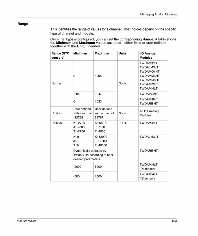
Managing Analog Modules
Range
This identifies the range of values for a channel. The choices depend on the specific type of channel and module.
Once the Type is configured, you can set the corresponding Range. A table shows the Minimum and Maximum values accepted - either fixed or user-defined - together with the Unit, if needed.
Range (NTC sensors)
Minimum Maximum Units I/O Analog Modules
Normal
0 4095
None
TWDAMI2LTTWDALM3LT TWDAMO1HT TWDAMM3HTTWDAMM6HTTWDAMI2HTTWDAMI4LT
-2048 2047 TWDAVO2HT
0 1023TWDAMI8HTTWDARI8HT
CustomUser defined with a min. of -32768
User defined with a max. of 32767
NoneAll I/O Analog Modules
Celsius K: -2700J: -2000T: -2700
K: 13700J: 7600T: 4000
0.1 °C TWDAMI2LT
K: 0J: 0T: 0
K: 13000J: 12000T: 40000
TWDALM3LT
Dynamically updated by TwidoSuite according to user-defined parameters
TWDARI8HT
-2000 6000TWDAMI4LT (Pt sensor)
-500 1500TWDAMI4LT (Ni sensor)
35011386 05/2009 163
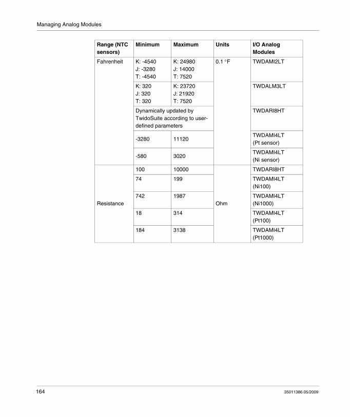
Managing Analog Modules
Fahrenheit K: -4540J: -3280 T: -4540
K: 24980J: 14000T: 7520
0.1 °F TWDAMI2LT
K: 320 J: 320T: 320
K: 23720J: 21920T: 7520
TWDALM3LT
Dynamically updated by TwidoSuite according to user-defined parameters
TWDARI8HT
-3280 11120TWDAMI4LT (Pt sensor)
-580 3020TWDAMI4LT (Ni sensor)
Resistance
100 10000
Ohm
TWDARI8HT
74 199 TWDAMI4LT (Ni100)
742 1987 TWDAMI4LT (Ni1000)
18 314 TWDAMI4LT (Pt100)
184 3138 TWDAMI4LT (Pt1000)
Range (NTC sensors)
Minimum Maximum Units I/O Analog Modules
164 35011386 05/2009
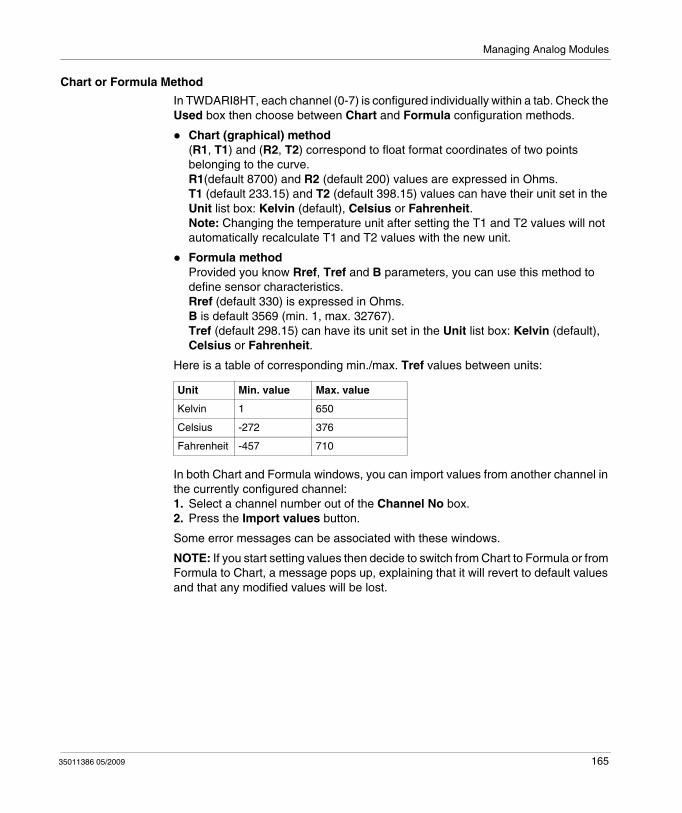
Managing Analog Modules
Chart or Formula Method
In TWDARI8HT, each channel (0-7) is configured individually within a tab. Check the Used box then choose between Chart and Formula configuration methods.
Chart (graphical) method(R1, T1) and (R2, T2) correspond to float format coordinates of two points belonging to the curve. R1(default 8700) and R2 (default 200) values are expressed in Ohms.T1 (default 233.15) and T2 (default 398.15) values can have their unit set in the Unit list box: Kelvin (default), Celsius or Fahrenheit.Note: Changing the temperature unit after setting the T1 and T2 values will not automatically recalculate T1 and T2 values with the new unit.
Formula methodProvided you know Rref, Tref and B parameters, you can use this method to define sensor characteristics.Rref (default 330) is expressed in Ohms.B is default 3569 (min. 1, max. 32767).Tref (default 298.15) can have its unit set in the Unit list box: Kelvin (default), Celsius or Fahrenheit.
Here is a table of corresponding min./max. Tref values between units:
In both Chart and Formula windows, you can import values from another channel in the currently configured channel:1. Select a channel number out of the Channel No box.2. Press the Import values button.
Some error messages can be associated with these windows.
NOTE: If you start setting values then decide to switch from Chart to Formula or from Formula to Chart, a message pops up, explaining that it will revert to default values and that any modified values will be lost.
Unit Min. value Max. value
Kelvin 1 650
Celsius -272 376
Fahrenheit -457 710
35011386 05/2009 165
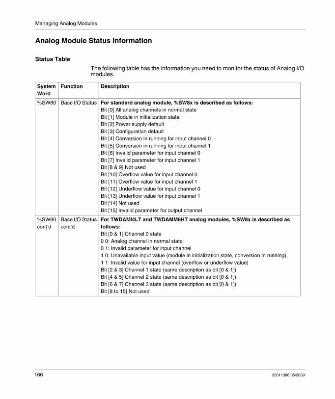
Managing Analog Modules
Analog Module Status Information
Status Table
The following table has the information you need to monitor the status of Analog I/O modules.
System Word
Function Description
%SW80 Base I/O Status For standard analog module, %SW8x is described as follows:Bit [0] All analog channels in normal stateBit [1] Module in initialization stateBit [2] Power supply defaultBit [3] Configuration defaultBit [4] Conversion in running for input channel 0Bit [5] Conversion in running for input channel 1Bit [6] Invalid parameter for input channel 0Bit [7] Invalid parameter for input channel 1Bit [8 & 9] Not usedBit [10] Overflow value for input channel 0Bit [11] Overflow value for input channel 1Bit [12] Underflow value for input channel 0Bit [13] Underflow value for input channel 1Bit [14] Not usedBit [15] Invalid parameter for output channel
%SW80cont’d
Base I/O Statuscont’d
For TWDAMI4LT and TWDAMM6HT analog modules, %SW8x is described as follows:Bit [0 & 1] Channel 0 state0 0: Analog channel in normal state0 1: Invalid parameter for input channel1 0: Unavailable input value (module in initialization state, conversion in running),1 1: Invalid value for input channel (overflow or underflow value)Bit [2 & 3] Channel 1 state (same description as bit [0 & 1])Bit [4 & 5] Channel 2 state (same description as bit [0 & 1])Bit [6 & 7] Channel 3 state (same description as bit [0 & 1])Bit [8 to 15] Not used
166 35011386 05/2009
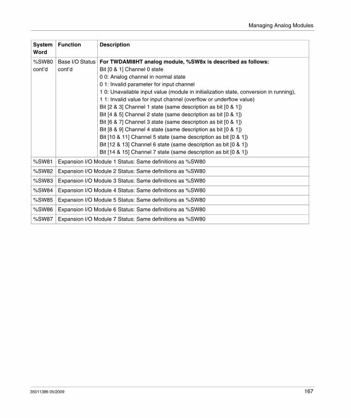
Managing Analog Modules
%SW80cont’d
Base I/O Statuscont’d
For TWDAMI8HT analog module, %SW8x is described as follows:Bit [0 & 1] Channel 0 state0 0: Analog channel in normal state0 1: Invalid parameter for input channel1 0: Unavailable input value (module in initialization state, conversion in running),1 1: Invalid value for input channel (overflow or underflow value)Bit [2 & 3] Channel 1 state (same description as bit [0 & 1])Bit [4 & 5] Channel 2 state (same description as bit [0 & 1])Bit [6 & 7] Channel 3 state (same description as bit [0 & 1])Bit [8 & 9] Channel 4 state (same description as bit [0 & 1])Bit [10 & 11] Channel 5 state (same description as bit [0 & 1])Bit [12 & 13] Channel 6 state (same description as bit [0 & 1])Bit [14 & 15] Channel 7 state (same description as bit [0 & 1])
%SW81 Expansion I/O Module 1 Status: Same definitions as %SW80
%SW82 Expansion I/O Module 2 Status: Same definitions as %SW80
%SW83 Expansion I/O Module 3 Status: Same definitions as %SW80
%SW84 Expansion I/O Module 4 Status: Same definitions as %SW80
%SW85 Expansion I/O Module 5 Status: Same definitions as %SW80
%SW86 Expansion I/O Module 6 Status: Same definitions as %SW80
%SW87 Expansion I/O Module 7 Status: Same definitions as %SW80
System Word
Function Description
35011386 05/2009 167
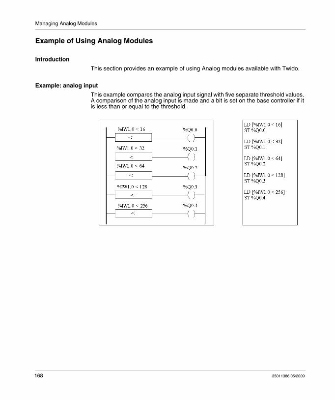
Managing Analog Modules
Example of Using Analog Modules
Introduction
This section provides an example of using Analog modules available with Twido.
Example: analog input
This example compares the analog input signal with five separate threshold values. A comparison of the analog input is made and a bit is set on the base controller if it is less than or equal to the threshold.
168 35011386 05/2009
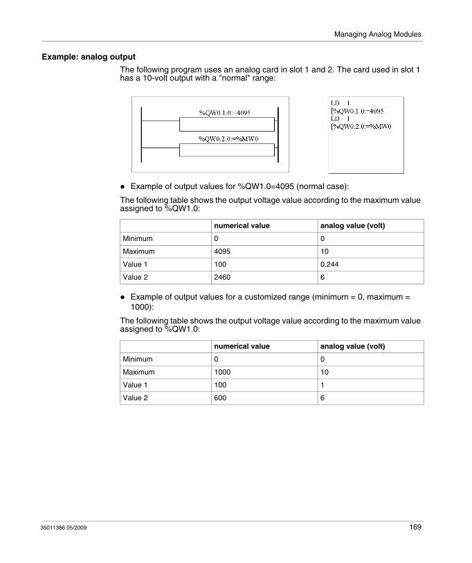
Managing Analog Modules
Example: analog output
The following program uses an analog card in slot 1 and 2. The card used in slot 1 has a 10-volt output with a "normal" range:
Example of output values for %QW1.0=4095 (normal case):
The following table shows the output voltage value according to the maximum value assigned to %QW1.0:
Example of output values for a customized range (minimum = 0, maximum = 1000):
The following table shows the output voltage value according to the maximum value assigned to %QW1.0:
numerical value analog value (volt)
Minimum 0 0
Maximum 4095 10
Value 1 100 0.244
Value 2 2460 6
numerical value analog value (volt)
Minimum 0 0
Maximum 1000 10
Value 1 100 1
Value 2 600 6
35011386 05/2009 169

Managing Analog Modules
170 35011386 05/2009
35011386 05/2009
8
Twido Extreme Input/Output Configuration
35011386 05/2009
Twido Extreme Input/Output Configuration
Subject of this Chapter
This chapter provides an overview of the Twido Extreme base inputs and outputs and describes input and output addressing.
What's in this Chapter?
This chapter contains the following sections:
Section Topic Page
8.1 An Introduction to Twido Extreme Inputs and Outputs 172
8.2 Twido Extreme Input Configuration 175
8.3 Twido Extreme Output Configuration 194
171
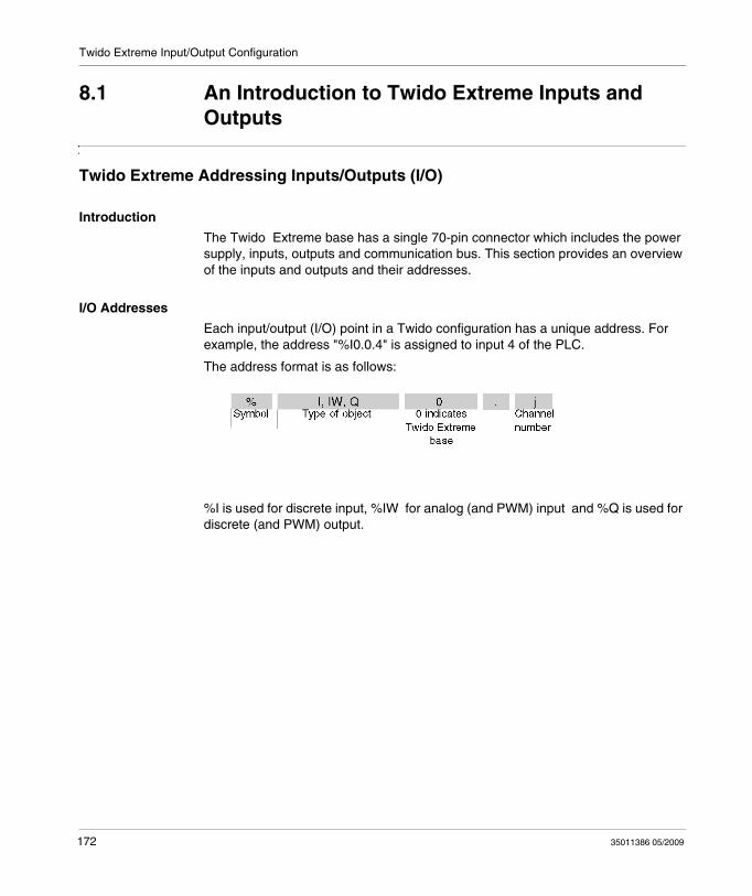
Twido Extreme Input/Output Configuration
8.1 An Introduction to Twido Extreme Inputs and Outputs
Twido Extreme Addressing Inputs/Outputs (I/O)
Introduction
The Twido Extreme base has a single 70-pin connector which includes the power supply, inputs, outputs and communication bus. This section provides an overview of the inputs and outputs and their addresses.
I/O Addresses
Each input/output (I/O) point in a Twido configuration has a unique address. For example, the address "%I0.0.4" is assigned to input 4 of the PLC.
The address format is as follows:
%I is used for discrete input, %IW for analog (and PWM) input and %Q is used for discrete (and PWM) output.
172 35011386 05/2009
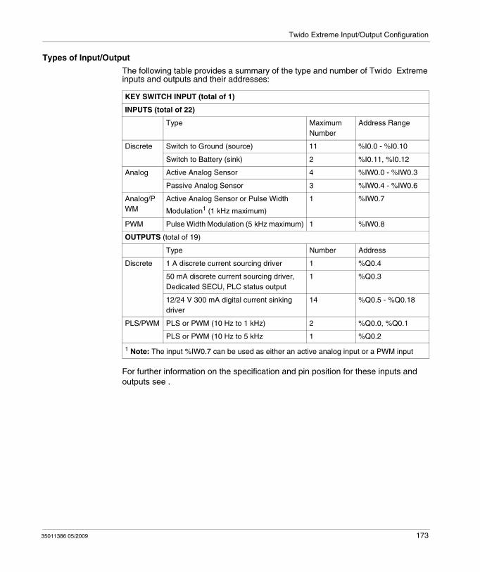
Twido Extreme Input/Output Configuration
Types of Input/Output
The following table provides a summary of the type and number of Twido Extreme inputs and outputs and their addresses:
For further information on the specification and pin position for these inputs and outputs see .
KEY SWITCH INPUT (total of 1)
INPUTS (total of 22)
Type Maximum Number
Address Range
Discrete Switch to Ground (source) 11 %I0.0 - %I0.10
Switch to Battery (sink) 2 %I0.11, %I0.12
Analog Active Analog Sensor 4 %IW0.0 - %IW0.3
Passive Analog Sensor 3 %IW0.4 - %IW0.6
Analog/PWM
Active Analog Sensor or Pulse Width
Modulation1 (1 kHz maximum)
1 %IW0.7
PWM Pulse Width Modulation (5 kHz maximum) 1 %IW0.8
OUTPUTS (total of 19)
Type Number Address
Discrete 1 A discrete current sourcing driver 1 %Q0.4
50 mA discrete current sourcing driver, Dedicated SECU, PLC status output
1 %Q0.3
12/24 V 300 mA digital current sinking driver
14 %Q0.5 - %Q0.18
PLS/PWM PLS or PWM (10 Hz to 1 kHz) 2 %Q0.0, %Q0.1
PLS or PWM (10 Hz to 5 kHz 1 %Q0.2
1 Note: The input %IW0.7 can be used as either an active analog input or a PWM input
35011386 05/2009 173
Twido Extreme Input/Output Configuration
Key Switch
The key switch is a special (physical) input which is used to: turn the Twido Extreme on and offset the Twido Extreme in standby mode.
NOTE: To enable WARM restart from standby mode, the Twido Extreme must not be disconnected from the power supply. If the power supply is not maintained, the controller performs a COLD restart and date and time information is lost.
In standby mode the Twido Extreme keeps RAM alive and RTC data intact but this implies that the PLC must be connected to the power supply (as it has no internal battery). To illustrate this further an analogy to a car ignition switch can be made. The key switch works like a car ignition switch which is linked to the car radio. When the engine is switched off, the car radio is also switched off, but the radio channels, time and other data are preserved in memory. As long as the radio is not disconnected from the car battery, when the motor is restarted the radio is restarted with all the data intact.
The key switch has not been allocated an address in the above table as this is a special type of input that cannot be configured in TwidoSuite and therefore has no dedicated address.
I/O Updates
Input bits (%I for discrete), input words (%IW for analog) and output (%Q) bits are used to exchange data between the user application and the discrete or analog channels. These objects are updated synchronously with the controller scan during RUN mode.
174 35011386 05/2009
Twido Extreme Input/Output Configuration
8.2 Twido Extreme Input Configuration
Subject of this Section
This section describes the input configuration for the Twido Extreme PLC.
What's in this Section?
This section contains the following topics:
Topic Page
Twido Extreme Discrete Input Configuration 176
Twido Extreme Analog Input Configuration 181
Twido Extreme PWM Input Configuration 186
Twido Extreme PWM Input Configuration Example 188
35011386 05/2009 175
Twido Extreme Input/Output Configuration
Twido Extreme Discrete Input Configuration
Introduction
This section describes the configuration of discrete inputs.
Discrete Input
There are two main types of discrete input:
Switch to Ground input Switch to Battery input (+)
Discrete input consist of Input Values, Rising Edge Values, and Falling Edge Values. The Rising and the Falling Edge values are computed from the current image and the previous image data from two consecutive scans.
Each input can be filtered, forced or latched
Input Filtering
Input filters reduce the effect of noise on the PLC input . Setting a filter value of 3 (or 12) ms ensures that sudden changes of input levels (due to noise) are ignored unless this new input level persists for 3 (or 12) ms.
Input Forcing
Forced values may be assigned to input (and output) values in a user-defined list/ladder program. This maybe useful for debugging purposes. This is described in forcing input/output values.
176 35011386 05/2009
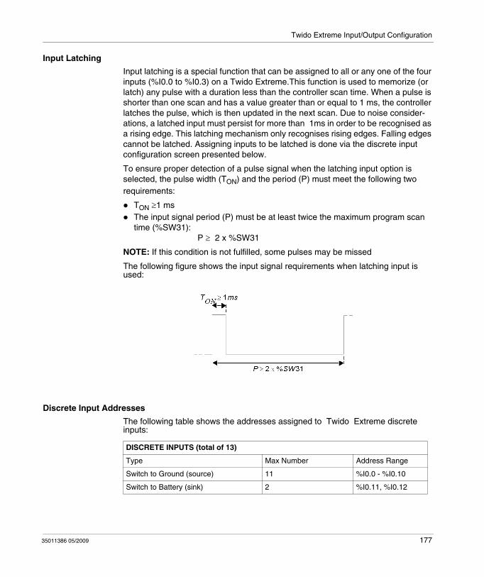
Twido Extreme Input/Output Configuration
Input Latching
Input latching is a special function that can be assigned to all or any one of the four inputs (%I0.0 to %I0.3) on a Twido Extreme.This function is used to memorize (or latch) any pulse with a duration less than the controller scan time. When a pulse is shorter than one scan and has a value greater than or equal to 1 ms, the controller latches the pulse, which is then updated in the next scan. Due to noise consider-ations, a latched input must persist for more than 1ms in order to be recognised as a rising edge. This latching mechanism only recognises rising edges. Falling edges cannot be latched. Assigning inputs to be latched is done via the discrete input configuration screen presented below.
To ensure proper detection of a pulse signal when the latching input option is selected, the pulse width (TON) and the period (P) must meet the following two requirements:
TON ≥1 msThe input signal period (P) must be at least twice the maximum program scan time (%SW31): P ≥ 2 x %SW31
NOTE: If this condition is not fulfilled, some pulses may be missed
The following figure shows the input signal requirements when latching input is used:
Discrete Input Addresses
The following table shows the addresses assigned to Twido Extreme discrete inputs:
DISCRETE INPUTS (total of 13)
Type Max Number Address Range
Switch to Ground (source) 11 %I0.0 - %I0.10
Switch to Battery (sink) 2 %I0.11, %I0.12
35011386 05/2009 177
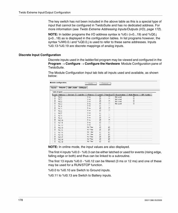
Twido Extreme Input/Output Configuration
The key switch has not been included in the above table as this is a special type of input that cannot be configured in TwidoSuite and has no dedicated address. For more information (see Twido Extreme Addressing Inputs/Outputs (I/O), page 172).
NOTE: In ladder programs the I/O address syntax is %I0.i (i=0...19) and %Q0.j (j=0...18) as is displayed in the configuration tables. In list programs however, the syntax %IW0.0.i and %Q0.0.j is used to refer to these same addresses. Inputs %I0.13-%I0.19 are discrete mappings of analog inputs.
Discrete Input Configuration
Discrete inputs used in the ladder/list program may be viewed and configured in the Program → Configure → Configure the Hardware Module Configuration pane of TwidoSuite.
The Module Configuration Input tab lists all inputs used and available, as shown below:
NOTE: In online mode, the input values are also displayed.
The first 4 inputs %I0.0 - %I0.3 can be either latched or used for events (rising edge, falling edge or both) and thus can be linked to a subroutine.
The first 13 inputs %I0.0 - %I0.12 can be filtered (3 ms or 12 ms) and one of these may be used for a RUN/STOP function.
%I0.0 to %I0.10 are Switch to Ground inputs.
%I0.11 to %I0.13 are Switch to Battery inputs.
178 35011386 05/2009
Twido Extreme Input/Output Configuration
The analog inputs %IW0.0 to %IW0.6 are associated with the discrete inputs %I0.13 to %I0.19 which change state depending on the corresponding analog values, as shown in the table below :
For example, if %IW0.0 ≥ 3.1V, %I0.13 changes from 0 to 1.
These inputs cannot be filtered or latched or associated to an event.
Input Configuration Fields
The input configuration fields displayed in the above figure are detailed in the following table. As indicated certain fields in this table are for display purposes only and cannot be modified.
Discrete Input Change of State Corresponding Analog Value
1 to 0 ≤1.2 V DC
0 to 1 ≥3.1 V DC
Field Possible Values Function
Used Check box selected or not.Selected relates to used.Cleared relates to unused.
For display purposes only. Displays inputs used by the program.
Address Input Addresses %I0.0-%I0.19 Address of each discrete input.
Symbol User defined value: alphanumeric max 32 characters. To provide name for input. This field can be edited. When applied, this name is then displayed in the Ladder/List program.
Used by user logic, Event For display purposes only. Lists any function blocks using this input, or indicates whether the input is used to trigger an event.
Filter Drop-down list box with following options:No filter3 ms12 ms
Filters are used to reduce the effect of noise on the PLC input.
Latch? Check box selected or not.This applies to only the first 4 inputs %I0.0 to %I0.3.Inputs with filters cannot be latched.Inputs associated with events cannot be latched.Selected relates to latched.Cleared relates to not latched.
Latching allows incoming pulses with amplitude widths shorter than the PLC scan time to be captured and recorded.
Run/Stop? Check box selected or not.This applies to only the first 13 inputs %I0.0 - %I0.12.Selected relates to RUN.Cleared relates to STOP.
To run or stop a PLC program.
35011386 05/2009 179
Twido Extreme Input/Output Configuration
Deactivation Drop-down list box with following options:Not usedRising edgeFalling edgeBoth edges
To configure whether an event is triggered by an input.
High Priority Check box selected or not.Only one input (%I0.0 to %I0.3) can be chosen.This can only be selected if there is an event triggered, (i.e., Deactivation field is anything other than "Not Used").
To make an event high priority (triggered).
SR Number A subroutine number selected from drop down list box.This can only be selected if there is an event triggered, (i.e., Deactivation field is anything other than "Not Used").
To assign a subroutine number to an event (triggered).
Field Possible Values Function
180 35011386 05/2009
Twido Extreme Input/Output Configuration
Twido Extreme Analog Input Configuration
Introduction
This section describes the configuration of analog inputs and provides an example.
Analog Input
There are three types of analog input :
Active (Sensor) Analog inputPassive (Sensor) Analog inputPWM input
Active sensors use external power to provide signals.
Passive sensors use part of the signal energy.
PWM inputs are described in the next section.
Analog Input Addresses
The following table shows the addresses assigned to Twido Extreme analog inputs:
ANALOG INPUTS (total of 9)
Type Max Number Address Range
Active 4 %IW0.0 - %IW0.3
Passive 3 %IW0.4 - %IW0.6
Analog/PWM 1 %IW0.7
PWM 1 %IW0.8
35011386 05/2009 181
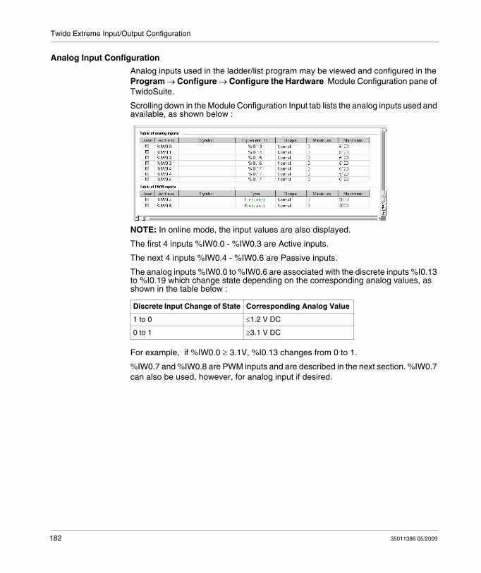
Twido Extreme Input/Output Configuration
Analog Input Configuration
Analog inputs used in the ladder/list program may be viewed and configured in the Program → Configure → Configure the Hardware Module Configuration pane of TwidoSuite.
Scrolling down in the Module Configuration Input tab lists the analog inputs used and available, as shown below :
NOTE: In online mode, the input values are also displayed.
The first 4 inputs %IW0.0 - %IW0.3 are Active inputs.
The next 4 inputs %IW0.4 - %IW0.6 are Passive inputs.
The analog inputs %IW0.0 to %IW0.6 are associated with the discrete inputs %I0.13 to %I0.19 which change state depending on the corresponding analog values, as shown in the table below :
For example, if %IW0.0 ≥ 3.1V, %I0.13 changes from 0 to 1.
%IW0.7 and %IW0.8 are PWM inputs and are described in the next section. %IW0.7 can also be used, however, for analog input if desired.
Discrete Input Change of State Corresponding Analog Value
1 to 0 ≤1.2 V DC
0 to 1 ≥3.1 V DC
182 35011386 05/2009
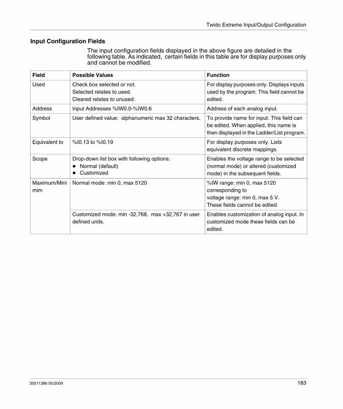
Twido Extreme Input/Output Configuration
Input Configuration Fields
The input configuration fields displayed in the above figure are detailed in the following table. As indicated, certain fields in this table are for display purposes only and cannot be modified.
Field Possible Values Function
Used Check box selected or not.Selected relates to used.Cleared relates to unused.
For display purposes only. Displays inputs used by the program. This field cannot be edited.
Address Input Addresses %IW0.0-%IW0.6 Address of each analog input.
Symbol User defined value: alphanumeric max 32 characters. To provide name for input. This field can be edited. When applied, this name is then displayed in the Ladder/List program.
Equivalent to %I0.13 to %I0.19 For display purposes only. Lists equivalent discrete mappings.
Scope Drop-down list box with following options:Normal (default)Customized
Enables the voltage range to be selected (normal mode) or altered (customized mode) in the subsequent fields.
Maximum/Minimim
Normal mode: min 0, max 5120 %IW range: min 0, max 5120corresponding tovoltage range: min 0, max 5 V.These fields cannot be edited.
Customized mode: min -32,768, max +32,767 in user defined units.
Enables customization of analog input. In customized mode these fields can be edited.
35011386 05/2009 183
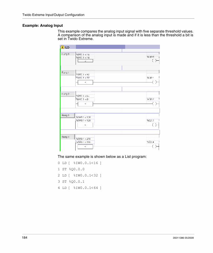
Twido Extreme Input/Output Configuration
Example: Analog Input
This example compares the analog input signal with five separate threshold values. A comparison of the analog input is made and if it is less than the threshold a bit is set in Twido Extreme.
The same example is shown below as a List program:
0 LD [ %IW0.0.1<16 ]
1 ST %Q0.0.0
2 LD [ %IW0.0.1<32 ]
3 ST %Q0.0.1
4 LD [ %IW0.0.1<64 ]
184 35011386 05/2009

Twido Extreme Input/Output Configuration
5 ST %Q0.0.2
6 LD [ %IW0.0.1<128 ]
7 ST %Q0.0.3
8 LD [ %IW0.0.0<256 ]
9 ST %Q0.0.4
NOTE: In ladder programs the I/O address syntax is %IW0.i (i=0...8) and %Q0.j (j=0...18) as is displayed in the configuration tables. In list programs however, the syntax %IW0.0.i and %Q0.0.j is used to refer to these same addresses.
35011386 05/2009 185
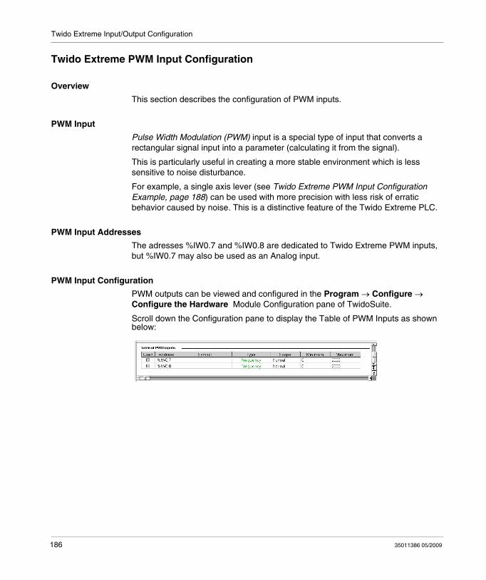
Twido Extreme Input/Output Configuration
Twido Extreme PWM Input Configuration
Overview
This section describes the configuration of PWM inputs.
PWM Input
Pulse Width Modulation (PWM) input is a special type of input that converts a rectangular signal input into a parameter (calculating it from the signal).
This is particularly useful in creating a more stable environment which is less sensitive to noise disturbance.
For example, a single axis lever (see Twido Extreme PWM Input Configuration Example, page 188) can be used with more precision with less risk of erratic behavior caused by noise. This is a distinctive feature of the Twido Extreme PLC.
PWM Input Addresses
The adresses %IW0.7 and %IW0.8 are dedicated to Twido Extreme PWM inputs, but %IW0.7 may also be used as an Analog input.
PWM Input Configuration
PWM outputs can be viewed and configured in the Program → Configure → Configure the Hardware Module Configuration pane of TwidoSuite.
Scroll down the Configuration pane to display the Table of PWM Inputs as shown below:
186 35011386 05/2009
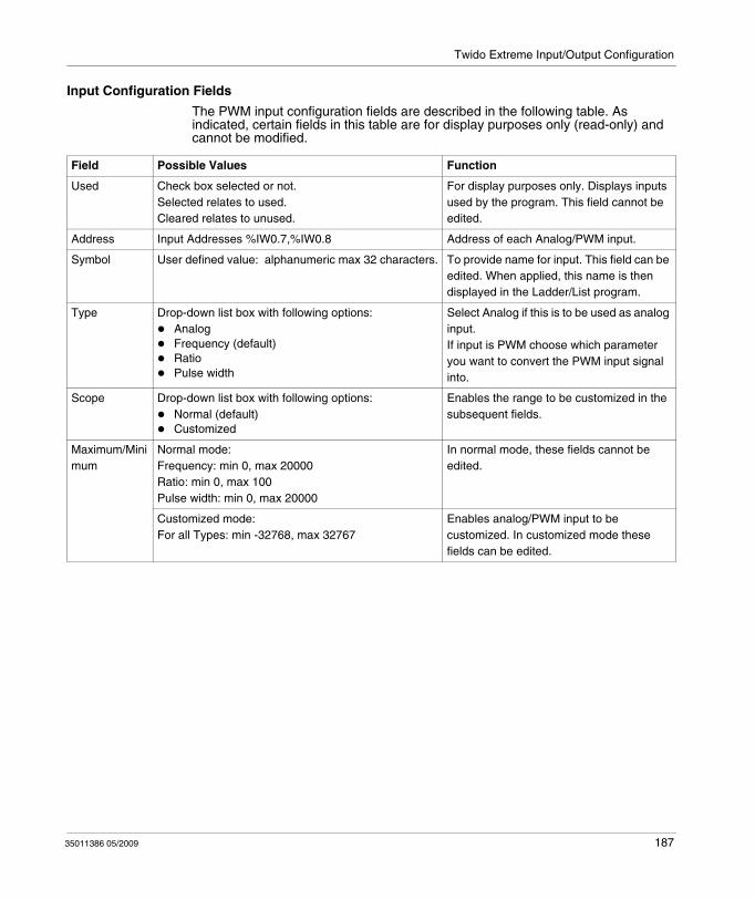
Twido Extreme Input/Output Configuration
Input Configuration Fields
The PWM input configuration fields are described in the following table. As indicated, certain fields in this table are for display purposes only (read-only) and cannot be modified.
Field Possible Values Function
Used Check box selected or not.Selected relates to used.Cleared relates to unused.
For display purposes only. Displays inputs used by the program. This field cannot be edited.
Address Input Addresses %IW0.7,%IW0.8 Address of each Analog/PWM input.
Symbol User defined value: alphanumeric max 32 characters. To provide name for input. This field can be edited. When applied, this name is then displayed in the Ladder/List program.
Type Drop-down list box with following options:AnalogFrequency (default)RatioPulse width
Select Analog if this is to be used as analog input.If input is PWM choose which parameter you want to convert the PWM input signal into.
Scope Drop-down list box with following options:Normal (default)Customized
Enables the range to be customized in the subsequent fields.
Maximum/Minimum
Normal mode:Frequency: min 0, max 20000Ratio: min 0, max 100Pulse width: min 0, max 20000
In normal mode, these fields cannot be edited.
Customized mode: For all Types: min -32768, max 32767
Enables analog/PWM input to be customized. In customized mode these fields can be edited.
35011386 05/2009 187
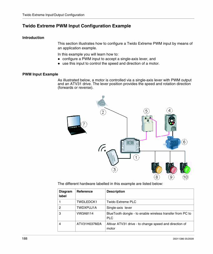
Twido Extreme Input/Output Configuration
Twido Extreme PWM Input Configuration Example
Introduction
This section illustrates how to configure a Twido Extreme PWM input by means of an application example.
In this example you will learn how to:configure a PWM input to accept a single-axis lever, anduse this input to control the speed and direction of a motor.
PWM Input Example
As illustrated below, a motor is controlled via a single-axis lever with PWM output and an ATV31 drive. The lever position provides the speed and rotation direction (forwards or reverse).
The different hardware labelled in this example are listed below:
Diagram label
Reference Description
1 TWDLEDCK1 Twido Extreme PLC
2 TWDXPUJ1A Single-axis lever
3 VW3A8114 BlueTooth dongle - to enable wireless transfer from PC to PLC
4 ATV31H037M2A Altivar ATV31 drive - to change speed and direction of motor
188 35011386 05/2009
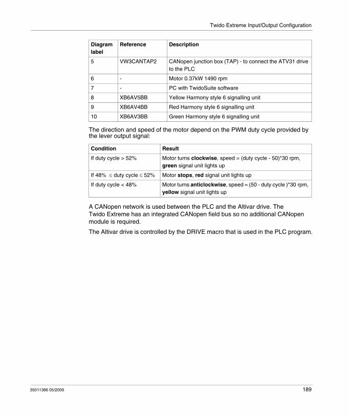
Twido Extreme Input/Output Configuration
The direction and speed of the motor depend on the PWM duty cycle provided by the lever output signal:
A CANopen network is used between the PLC and the Altivar drive. The Twido Extreme has an integrated CANopen field bus so no additional CANopen module is required.
The Altivar drive is controlled by the DRIVE macro that is used in the PLC program.
5 VW3CANTAP2 CANopen junction box (TAP) - to connect the ATV31 drive to the PLC
6 - Motor 0.37kW 1490 rpm
7 - PC with TwidoSuite software
8 XB6AV5BB Yellow Harmony style 6 signalling unit
9 XB6AV4BB Red Harmony style 6 signalling unit
10 XB6AV3BB Green Harmony style 6 signalling unit
Condition Result
If duty cycle > 52% Motor turns clockwise, speed = (duty cycle - 50)*30 rpm, green signal unit lights up
If 48% ≤ duty cycle ≤ 52% Motor stops, red signal unit lights up
If duty cycle < 48% Motor turns anticlockwise, speed = (50 - duty cycle )*30 rpm, yellow signal unit lights up
Diagram label
Reference Description
35011386 05/2009 189
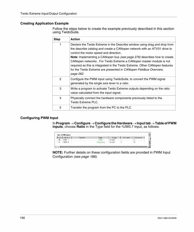
Twido Extreme Input/Output Configuration
Creating Application Example
Follow the steps below to create the example previously described in this section using TwidoSuite.
Configuring PWM Input
In Program → Configure → Configure the Hardware → Input tab → Table of PWM inputs, choose Ratio in the Type field for the %IW0.7 input, as follows:
NOTE: Further details on these configuration fields are provided in PWM Input Configuration (see page 186).
Step Action
1 Declare the Twido Extreme in the Describe window using drag and drop from the describe catalog and create a CANopen network with an ATV31 drive to control the motor speed and direction.Note: Implementing a CANopen bus (see page 276) describes how to create CANopen networks . For Twido Extreme a CANopen master module is not required as this is integrated in the Twido Extreme. Other CANopen features for the Twido Extreme are presented in CANopen Fieldbus Overview, page 262.
2 Configure the PWM input using TwidoSuite, to convert the PWM signal generated by the single axis lever to a ratio.
3 Write a program to activate Twido Extreme outputs depending on the ratio value calculated from the input signal.
4 Physically connect the hardware components previously listed to the Twido Extreme PLC.
5 Transfer the program from the PC to the PLC.
190 35011386 05/2009
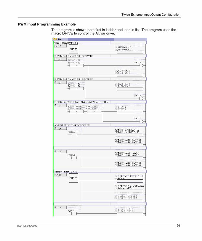
Twido Extreme Input/Output Configuration
PWM Input Programming Example
The program is shown here first in ladder and then in list. The program uses the macro DRIVE to control the Altivar drive.
35011386 05/2009 191
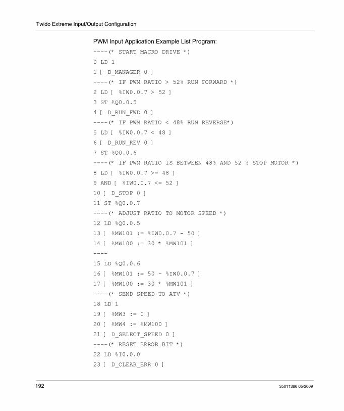
Twido Extreme Input/Output Configuration
PWM Input Application Example List Program:
----(* START MACRO DRIVE *)
0 LD 1
1 [ D_MANAGER 0 ]
----(* IF PWM RATIO > 52% RUN FORWARD *)
2 LD [ %IW0.0.7 > 52 ]
3 ST %Q0.0.5
4 [ D_RUN_FWD 0 ]
----(* IF PWM RATIO < 48% RUN REVERSE*)
5 LD [ %IW0.0.7 < 48 ]
6 [ D_RUN_REV 0 ]
7 ST %Q0.0.6
----(* IF PWM RATIO IS BETWEEN 48% AND 52 % STOP MOTOR *)
8 LD [ %IW0.0.7 >= 48 ]
9 AND [ %IW0.0.7 <= 52 ]
10 [ D_STOP 0 ]
11 ST %Q0.0.7
----(* ADJUST RATIO TO MOTOR SPEED *)
12 LD %Q0.0.5
13 [ %MW101 := %IW0.0.7 - 50 ]
14 [ %MW100 := 30 * %MW101 ]
----
15 LD %Q0.0.6
16 [ %MW101 := 50 - %IW0.0.7 ]
17 [ %MW100 := 30 * %MW101 ]
----(* SEND SPEED TO ATV *)
18 LD 1
19 [ %MW3 := 0 ]
20 [ %MW4 := %MW100 ]
21 [ D_SELECT_SPEED 0 ]
----(* RESET ERROR BIT *)
22 LD %I0.0.0
23 [ D_CLEAR_ERR 0 ]
192 35011386 05/2009
Twido Extreme Input/Output Configuration
Ladder/List I/O Syntax
NOTE: In ladder programs the I/O address syntax is %IW0.i (i=0...8) and %Q0.j (j=0...18) as is displayed in the configuration tables. In list programs however, the syntax %IW0.0.i and %Q0.0.j is used to refer to these same addresses.
Input/Output Connections
Connect the hardware inputs and outputs:Connect the output of the lever to the %IW0.7 Twido Extreme input.Connect the Altivar drive input via the junction box to the Twido Extreme CANopen port.Connect the Twido Extreme outputs %Q0.5, %Q0.6 and %Q0.7 to the signalling units to enable the system to be monitored.Connect the Altivar drive to the motor.Connect the BlueTooth dongle to the Twido Extreme for program transfer.
NOTE: For more information about the single-axis lever and I/O connections (see ).
35011386 05/2009 193
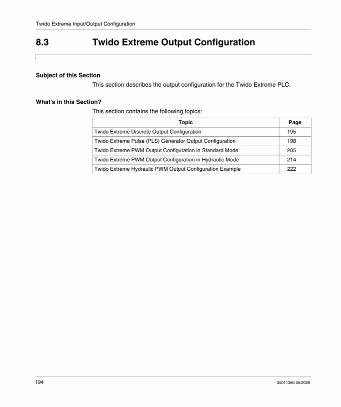
Twido Extreme Input/Output Configuration
8.3 Twido Extreme Output Configuration
Subject of this Section
This section describes the output configuration for the Twido Extreme PLC.
What's in this Section?
This section contains the following topics:
Topic Page
Twido Extreme Discrete Output Configuration 195
Twido Extreme Pulse (PLS) Generator Output Configuration 198
Twido Extreme PWM Output Configuration in Standard Mode 205
Twido Extreme PWM Output Configuration in Hydraulic Mode 214
Twido Extreme Hydraulic PWM Output Configuration Example 222
194 35011386 05/2009
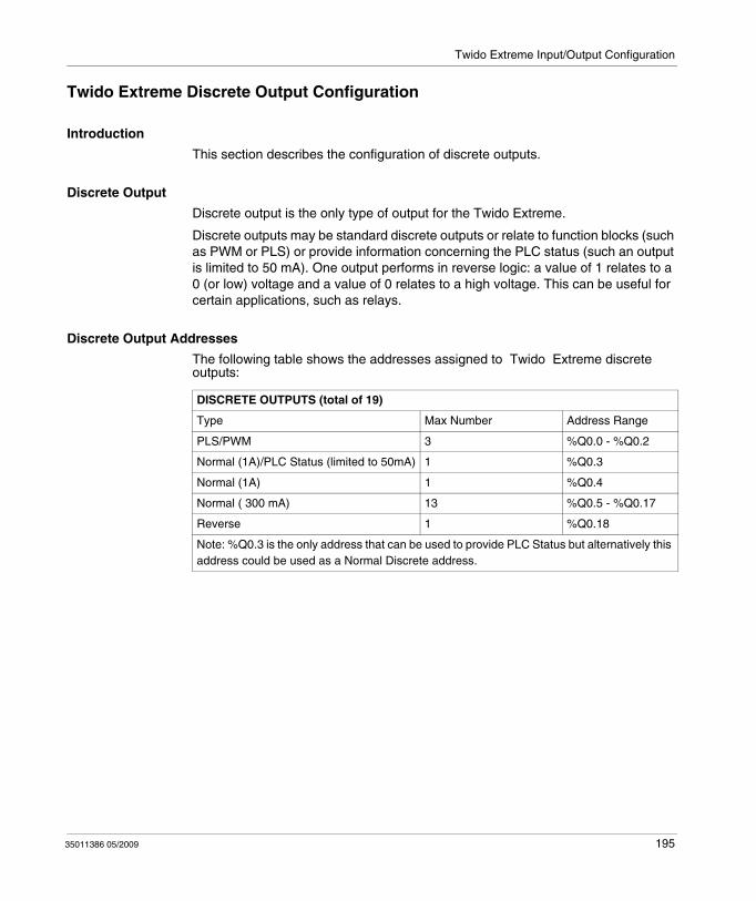
Twido Extreme Input/Output Configuration
Twido Extreme Discrete Output Configuration
Introduction
This section describes the configuration of discrete outputs.
Discrete Output
Discrete output is the only type of output for the Twido Extreme.
Discrete outputs may be standard discrete outputs or relate to function blocks (such as PWM or PLS) or provide information concerning the PLC status (such an output is limited to 50 mA). One output performs in reverse logic: a value of 1 relates to a 0 (or low) voltage and a value of 0 relates to a high voltage. This can be useful for certain applications, such as relays.
Discrete Output Addresses
The following table shows the addresses assigned to Twido Extreme discrete outputs:
DISCRETE OUTPUTS (total of 19)
Type Max Number Address Range
PLS/PWM 3 %Q0.0 - %Q0.2
Normal (1A)/PLC Status (limited to 50mA) 1 %Q0.3
Normal (1A) 1 %Q0.4
Normal ( 300 mA) 13 %Q0.5 - %Q0.17
Reverse 1 %Q0.18
Note: %Q0.3 is the only address that can be used to provide PLC Status but alternatively this address could be used as a Normal Discrete address.
35011386 05/2009 195
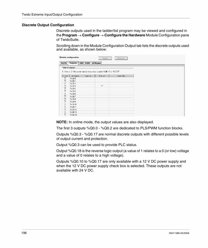
Twido Extreme Input/Output Configuration
Discrete Output Configuration
Discrete outputs used in the ladder/list program may be viewed and configured in the Program → Configure → Configure the Hardware Module Configuration pane of TwidoSuite.
Scrolling down in the Module Configuration Output tab lists the discrete outputs used and available, as shown below:
NOTE: In online mode, the output values are also displayed.
The first 3 outputs %Q0.0 - %Q0.2 are dedicated to PLS/PWM function blocks.
Outputs %Q0.3 - %Q0.17 are normal discrete outputs with different possible levels of output current and protection.
Output %Q0.3 can be used to provide PLC status.
Output %Q0.18 is the reverse logic output (a value of 1 relates to a 0 (or low) voltage and a value of 0 relates to a high voltage).
Outputs %Q0.10 to %Q0.17 are only available with a 12 V DC power supply and when the 12 V DC power supply check box is selected. These outputs are not available with 24 V DC.
196 35011386 05/2009
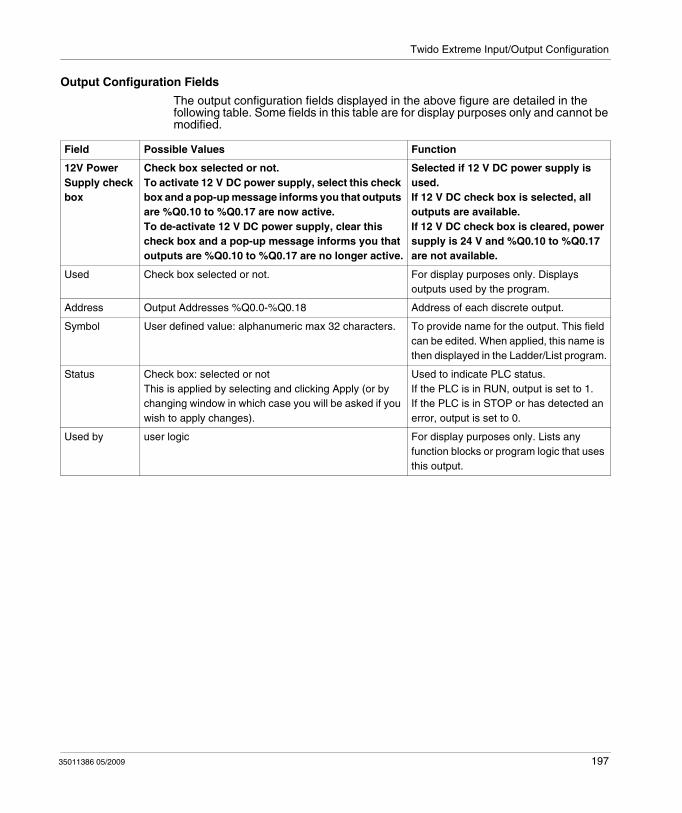
Twido Extreme Input/Output Configuration
Output Configuration Fields
The output configuration fields displayed in the above figure are detailed in the following table. Some fields in this table are for display purposes only and cannot be modified.
Field Possible Values Function
12V Power Supply check box
Check box selected or not.To activate 12 V DC power supply, select this check box and a pop-up message informs you that outputs are %Q0.10 to %Q0.17 are now active.To de-activate 12 V DC power supply, clear this check box and a pop-up message informs you that outputs are %Q0.10 to %Q0.17 are no longer active.
Selected if 12 V DC power supply is used.If 12 V DC check box is selected, all outputs are available.If 12 V DC check box is cleared, power supply is 24 V and %Q0.10 to %Q0.17 are not available.
Used Check box selected or not. For display purposes only. Displays outputs used by the program.
Address Output Addresses %Q0.0-%Q0.18 Address of each discrete output.
Symbol User defined value: alphanumeric max 32 characters. To provide name for the output. This field can be edited. When applied, this name is then displayed in the Ladder/List program.
Status Check box: selected or notThis is applied by selecting and clicking Apply (or by changing window in which case you will be asked if you wish to apply changes).
Used to indicate PLC status.If the PLC is in RUN, output is set to 1.If the PLC is in STOP or has detected an error, output is set to 0.
Used by user logic For display purposes only. Lists any function blocks or program logic that uses this output.
35011386 05/2009 197
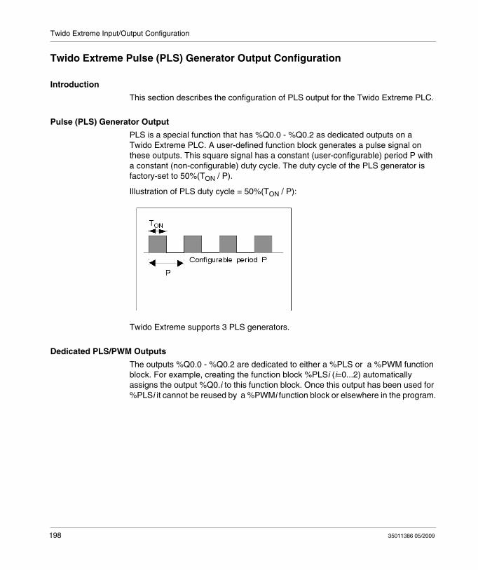
Twido Extreme Input/Output Configuration
Twido Extreme Pulse (PLS) Generator Output Configuration
Introduction
This section describes the configuration of PLS output for the Twido Extreme PLC.
Pulse (PLS) Generator Output
PLS is a special function that has %Q0.0 - %Q0.2 as dedicated outputs on a Twido Extreme PLC. A user-defined function block generates a pulse signal on these outputs. This square signal has a constant (user-configurable) period P with a constant (non-configurable) duty cycle. The duty cycle of the PLS generator is factory-set to 50%(TON / P).
Illustration of PLS duty cycle = 50%(TON / P):
Twido Extreme supports 3 PLS generators.
Dedicated PLS/PWM Outputs
The outputs %Q0.0 - %Q0.2 are dedicated to either a %PLS or a %PWM function block. For example, creating the function block %PLSi (i=0...2) automatically assigns the output %Q0.i to this function block. Once this output has been used for %PLSi it cannot be reused by a %PWMi function block or elsewhere in the program.
198 35011386 05/2009
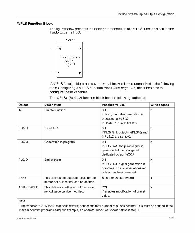
Twido Extreme Input/Output Configuration
%PLS Function Block
The figure below presents the ladder representation of a %PLS function block for the Twido Extreme PLC.
A %PLS function block has several variables which are summarized in the following table Configuring a %PLS Function Block (see page 201) describes how to configure these variables.
The %PLSi (i = 0...2) function block has the following variables:
Object Description Possible values Write access
IN Enable function 0,1If IN=1, the pulse generation is produced at PLSi.QIF IN=0, PLSi.Q is set to 0
N
PLSi.R Reset to 0 0,1If PLSi.R=1, outputs %PLSi.Q and %PLSi.D are set to 0.
N
PLSi.Q Generation in program 0,1If PLSi.Q=1, the pulse signal is generated at the configured dedicated output %Q0.i.
N
PLSi.D End of cycle 0,1If PLSi.D=1, signal generation is complete. The number of desired pulses has been reached.
N
TYPE This defines the possible range for the number of pulses that can be defined.
Single or Double (word) Y
ADJUSTABLE This defines whether or not the preset period value can be modified.
Y/NY enables modification of preset value.
Y
Note1 The variable PLSi.N (or ND for double word) defines the total number of pulses desired. This must be defined in the user’s ladder/list program using, for example, an operator block, as shown below in step 1.
35011386 05/2009 199
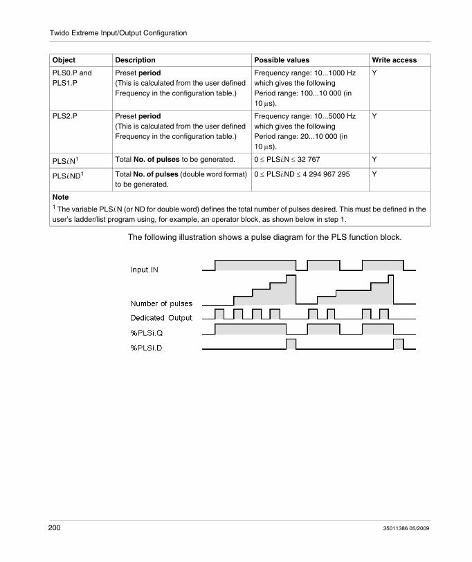
Twido Extreme Input/Output Configuration
The following illustration shows a pulse diagram for the PLS function block.
PLS0.P and PLS1.P
Preset period(This is calculated from the user defined Frequency in the configuration table.)
Frequency range: 10...1000 Hzwhich gives the followingPeriod range: 100...10 000 (in 10 μs).
Y
PLS2.P Preset period(This is calculated from the user defined Frequency in the configuration table.)
Frequency range: 10...5000 Hzwhich gives the followingPeriod range: 20...10 000 (in 10 μs).
Y
PLSi.N1 Total No. of pulses to be generated. 0 ≤ PLSi.N ≤ 32 767 Y
PLSi.ND1 Total No. of pulses (double word format) to be generated.
0 ≤ PLSi.ND ≤ 4 294 967 295 Y
Object Description Possible values Write access
Note1 The variable PLSi.N (or ND for double word) defines the total number of pulses desired. This must be defined in the user’s ladder/list program using, for example, an operator block, as shown below in step 1.
200 35011386 05/2009
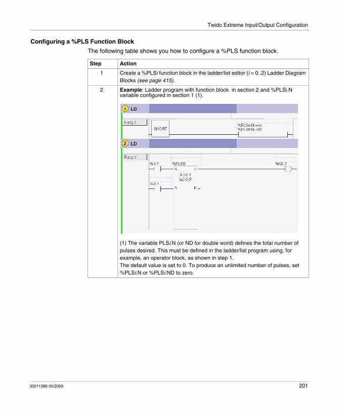
Twido Extreme Input/Output Configuration
Configuring a %PLS Function Block
The following table shows you how to configure a %PLS function block.
Step Action
1 Create a %PLSi function block in the ladder/list editor (i = 0..2) Ladder Diagram Blocks (see page 415).
2 Example: Ladder program with function block in section 2 and %PLSi.N variable configured in section 1 (1).
(1) The variable PLSi.N (or ND for double word) defines the total number of pulses desired. This must be defined in the ladder/list program using, for example, an operator block, as shown in step 1.The default value is set to 0. To produce an unlimited number of pulses, set %PLSi.N or %PLSi.ND to zero.
35011386 05/2009 201
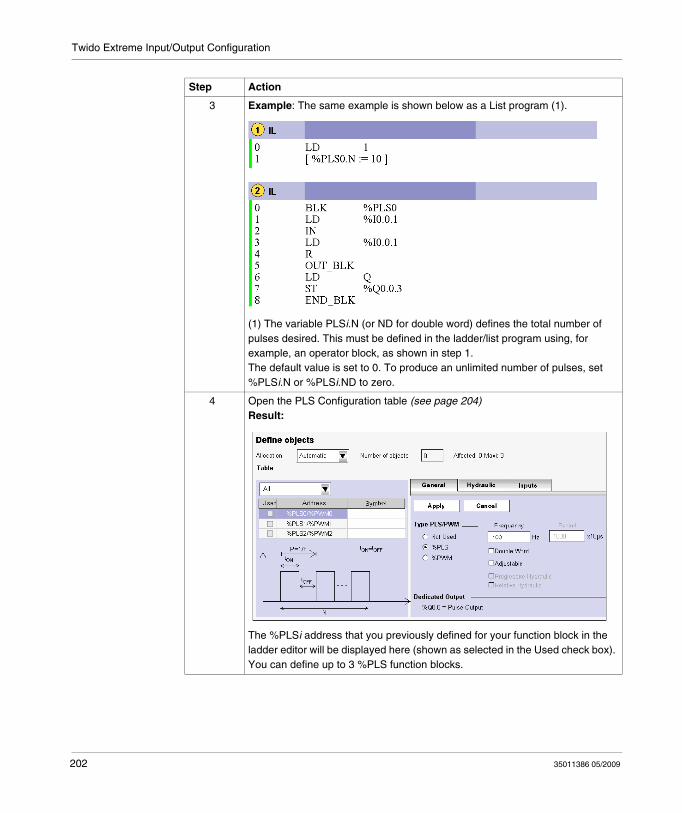
Twido Extreme Input/Output Configuration
3 Example: The same example is shown below as a List program (1).
(1) The variable PLSi.N (or ND for double word) defines the total number of pulses desired. This must be defined in the ladder/list program using, for example, an operator block, as shown in step 1.The default value is set to 0. To produce an unlimited number of pulses, set %PLSi.N or %PLSi.ND to zero.
4 Open the PLS Configuration table (see page 204)Result:
The %PLSi address that you previously defined for your function block in the ladder editor will be displayed here (shown as selected in the Used check box). You can define up to 3 %PLS function blocks.
Step Action
202 35011386 05/2009
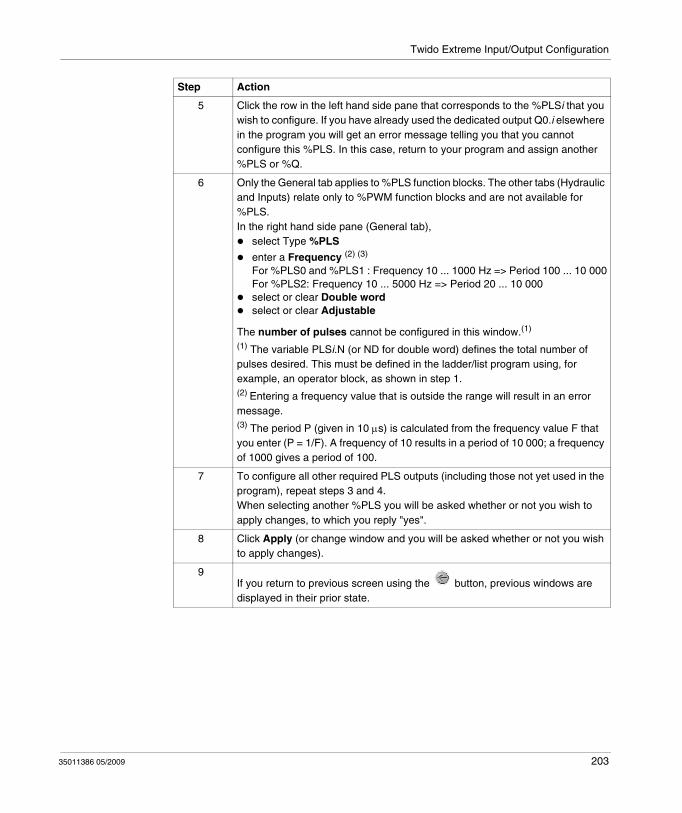
Twido Extreme Input/Output Configuration
5 Click the row in the left hand side pane that corresponds to the %PLSi that you wish to configure. If you have already used the dedicated output Q0.i elsewhere in the program you will get an error message telling you that you cannot configure this %PLS. In this case, return to your program and assign another %PLS or %Q.
6 Only the General tab applies to %PLS function blocks. The other tabs (Hydraulic and Inputs) relate only to %PWM function blocks and are not available for %PLS.In the right hand side pane (General tab),
select Type %PLS
enter a Frequency (2) (3)
For %PLS0 and %PLS1 : Frequency 10 ... 1000 Hz => Period 100 ... 10 000For %PLS2: Frequency 10 ... 5000 Hz => Period 20 ... 10 000select or clear Double wordselect or clear Adjustable
The number of pulses cannot be configured in this window.(1)
(1) The variable PLSi.N (or ND for double word) defines the total number of pulses desired. This must be defined in the ladder/list program using, for example, an operator block, as shown in step 1.(2) Entering a frequency value that is outside the range will result in an error message.(3) The period P (given in 10 μs) is calculated from the frequency value F that you enter (P = 1/F). A frequency of 10 results in a period of 10 000; a frequency of 1000 gives a period of 100.
7 To configure all other required PLS outputs (including those not yet used in the program), repeat steps 3 and 4.When selecting another %PLS you will be asked whether or not you wish to apply changes, to which you reply "yes".
8 Click Apply (or change window and you will be asked whether or not you wish to apply changes).
9If you return to previous screen using the button, previous windows are displayed in their prior state.
Step Action
35011386 05/2009 203
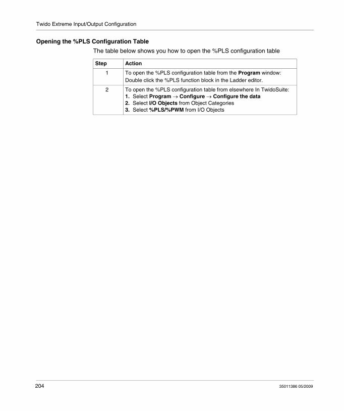
Twido Extreme Input/Output Configuration
Opening the %PLS Configuration Table
The table below shows you how to open the %PLS configuration table
Step Action
1 To open the %PLS configuration table from the Program window:Double click the %PLS function block in the Ladder editor.
2 To open the %PLS configuration table from elsewhere In TwidoSuite:1. Select Program → Configure → Configure the data2. Select I/O Objects from Object Categories3. Select %PLS/%PWM from I/O Objects
204 35011386 05/2009
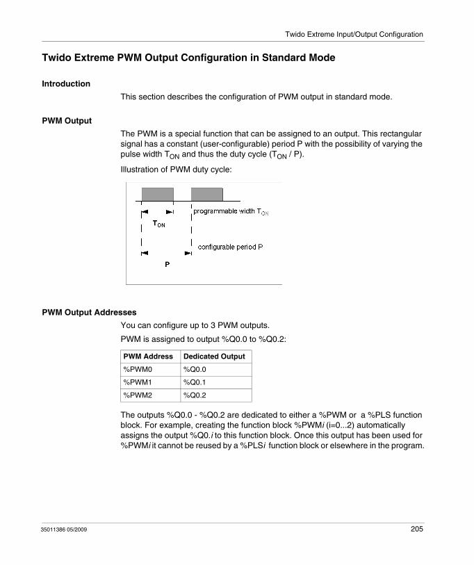
Twido Extreme Input/Output Configuration
Twido Extreme PWM Output Configuration in Standard Mode
Introduction
This section describes the configuration of PWM output in standard mode.
PWM Output
The PWM is a special function that can be assigned to an output. This rectangular signal has a constant (user-configurable) period P with the possibility of varying the pulse width TON and thus the duty cycle (TON / P).
Illustration of PWM duty cycle:
PWM Output Addresses
You can configure up to 3 PWM outputs.
PWM is assigned to output %Q0.0 to %Q0.2:
The outputs %Q0.0 - %Q0.2 are dedicated to either a %PWM or a %PLS function block. For example, creating the function block %PWMi (i=0...2) automatically assigns the output %Q0.i to this function block. Once this output has been used for %PWMi it cannot be reused by a %PLSi function block or elsewhere in the program.
PWM Address Dedicated Output
%PWM0 %Q0.0
%PWM1 %Q0.1
%PWM2 %Q0.2
35011386 05/2009 205
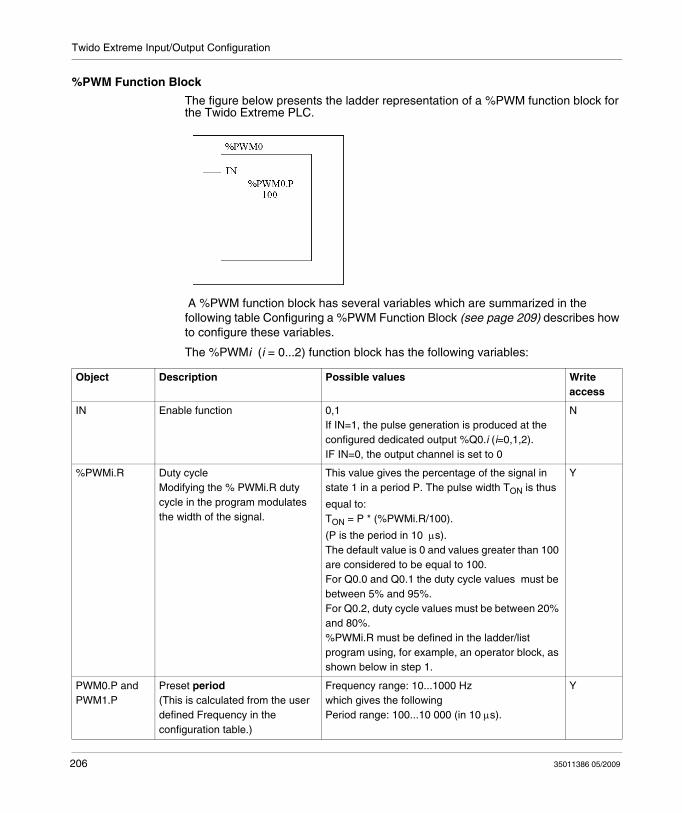
Twido Extreme Input/Output Configuration
%PWM Function Block
The figure below presents the ladder representation of a %PWM function block for the Twido Extreme PLC.
A %PWM function block has several variables which are summarized in the following table Configuring a %PWM Function Block (see page 209) describes how to configure these variables.
The %PWMi (i = 0...2) function block has the following variables:
Object Description Possible values Write access
IN Enable function 0,1If IN=1, the pulse generation is produced at the configured dedicated output %Q0.i (i=0,1,2).IF IN=0, the output channel is set to 0
N
%PWMi.R Duty cycleModifying the % PWMi.R duty cycle in the program modulates the width of the signal.
This value gives the percentage of the signal in state 1 in a period P. The pulse width TON is thus
equal to:TON = P * (%PWMi.R/100).
(P is the period in 10 μs). The default value is 0 and values greater than 100 are considered to be equal to 100.For Q0.0 and Q0.1 the duty cycle values must be between 5% and 95%.For Q0.2, duty cycle values must be between 20% and 80%.%PWMi.R must be defined in the ladder/list program using, for example, an operator block, as shown below in step 1.
Y
PWM0.P and PWM1.P
Preset period(This is calculated from the user defined Frequency in the configuration table.)
Frequency range: 10...1000 Hzwhich gives the followingPeriod range: 100...10 000 (in 10 μs).
Y
206 35011386 05/2009
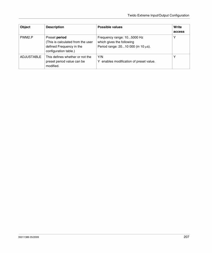
Twido Extreme Input/Output Configuration
PWM2.P Preset period(This is calculated from the user defined Frequency in the configuration table.)
Frequency range: 10...5000 Hzwhich gives the followingPeriod range: 20...10 000 (in 10 μs).
Y
ADJUSTABLE This defines whether or not the preset period value can be modified.
Y/NY enables modification of preset value.
Y
Object Description Possible values Write access
35011386 05/2009 207
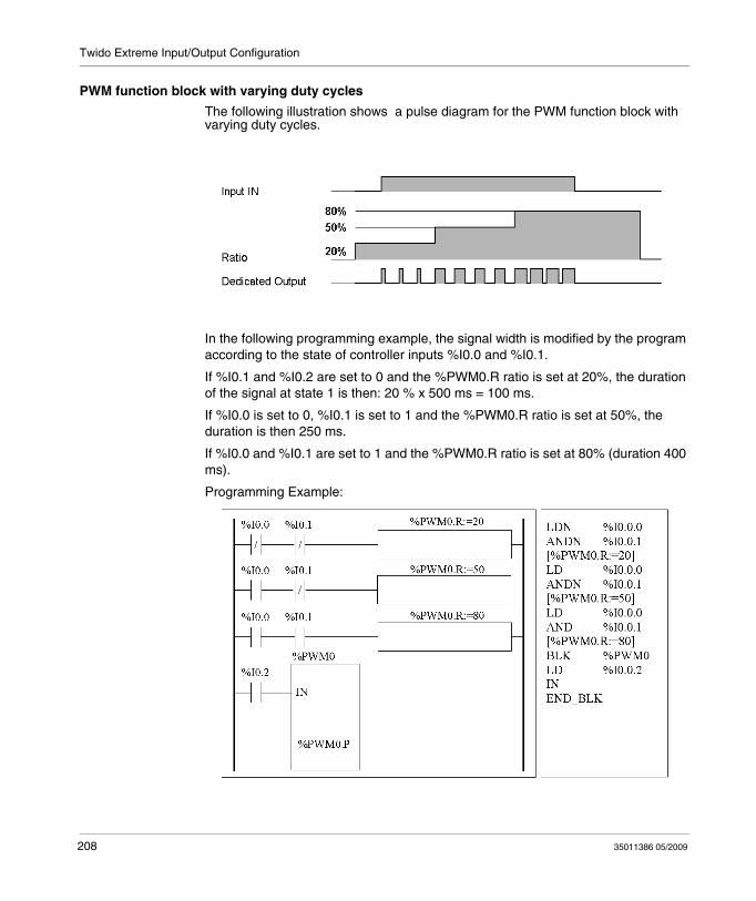
Twido Extreme Input/Output Configuration
PWM function block with varying duty cycles
The following illustration shows a pulse diagram for the PWM function block with varying duty cycles.
In the following programming example, the signal width is modified by the program according to the state of controller inputs %I0.0 and %I0.1.
If %I0.1 and %I0.2 are set to 0 and the %PWM0.R ratio is set at 20%, the duration of the signal at state 1 is then: 20 % x 500 ms = 100 ms.
If %I0.0 is set to 0, %I0.1 is set to 1 and the %PWM0.R ratio is set at 50%, the duration is then 250 ms.
If %I0.0 and %I0.1 are set to 1 and the %PWM0.R ratio is set at 80% (duration 400 ms).
Programming Example:
208 35011386 05/2009
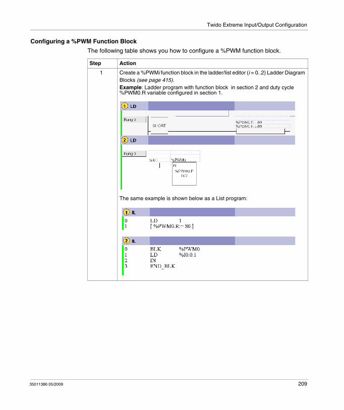
Twido Extreme Input/Output Configuration
Configuring a %PWM Function Block
The following table shows you how to configure a %PWM function block.
Step Action
1 Create a %PWMi function block in the ladder/list editor (i = 0..2) Ladder Diagram Blocks (see page 415).Example: Ladder program with function block in section 2 and duty cycle %PWM0.R variable configured in section 1.
The same example is shown below as a List program:
35011386 05/2009 209
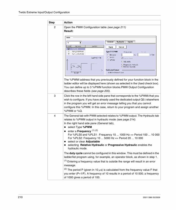
Twido Extreme Input/Output Configuration
2 Open the PMW Configuration table (see page 211)Result:
The %PWMi address that you previously defined for your function block in the ladder editor will be displayed here (shown as selected in the Used check box). You can define up to 3 %PWM function blocks.PMW Output Configuration describes these fields (see page 205).
3 Click the row in the left hand side pane that corresponds to the %PWMi that you wish to configure. If you have already used the dedicated output Q0.i elsewhere in the program you will get an error message telling you that you cannot configure this %PWM. In this case, return to your program and assign another %PWM or %Q.
4 The General tab with PWM selected relates to %PWM output. The Hydraulic tab relates to %PWM output in hydraulic mode (see page 214).In the right hand side pane (General tab),
select Type %PWM
enter a Frequency (1) (2)
For %PLS0 and %PLS1 : Frequency 10 ... 1000 Hz => Period 100 ... 10 000For %PLS2: Frequency 10 ... 5000 Hz => Period 20 ... 10 000select or clear Adjustableselecting Relative Hydraulic or Progressive Hydraulic enables the hydraulic mode.
The duty cycle cannot be configured in this window. This must be defined in the ladder/list program using, for example, an operator block, as shown in step 1.(1) Entering a frequency value that is outside the range will result in an error message.(2) The period P (given in 10 μs) is calculated from the frequency value F that you enter (P=1/F). A frequency of 10 results in a period of 10 000; a frequency of 1000 gives a period of 100.
Step Action
210 35011386 05/2009
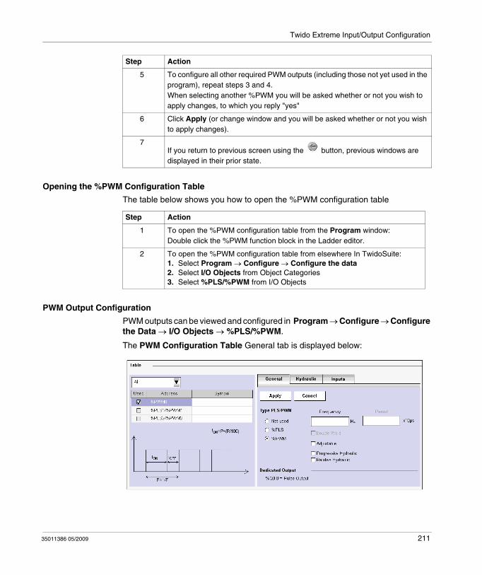
Twido Extreme Input/Output Configuration
Opening the %PWM Configuration Table
The table below shows you how to open the %PWM configuration table
PWM Output Configuration
PWM outputs can be viewed and configured in Program → Configure → Configure the Data → I/O Objects → %PLS/%PWM.
The PWM Configuration Table General tab is displayed below:
5 To configure all other required PWM outputs (including those not yet used in the program), repeat steps 3 and 4.When selecting another %PWM you will be asked whether or not you wish to apply changes, to which you reply "yes"
6 Click Apply (or change window and you will be asked whether or not you wish to apply changes).
7If you return to previous screen using the button, previous windows are displayed in their prior state.
Step Action
Step Action
1 To open the %PWM configuration table from the Program window:Double click the %PWM function block in the Ladder editor.
2 To open the %PWM configuration table from elsewhere In TwidoSuite:1. Select Program → Configure → Configure the data2. Select I/O Objects from Object Categories3. Select %PLS/%PWM from I/O Objects
35011386 05/2009 211
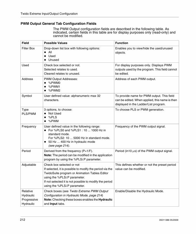
Twido Extreme Input/Output Configuration
PWM Output General Tab Configuration Fields
The PWM Output configuration fields are described in the following table. As indicated, certain fields in this table are for display purposes only (read-only) and cannot be modified.
Field Possible Values Function
Filter Box Drop-down list box with following options:AllUsedUnused
Enables you to view/hide the used/unused objects.
Used Check box selected or not.Selected relates to used.Cleared relates to unused.
For display purposes only. Displays PWM outputs used by the program. This field cannot be edited.
Address PWM Output Addresses:%PWM0%PWM1%PWM2
Address of each PWM output.
Symbol User defined value: alphanumeric max 32 characters.
To provide name for PWM output. This field can be edited. When applied, this name is then displayed in the Ladder/List program.
Type PLS/PWM
3 options, to choose:Not Used%PLS%PWM
To choose PLS or PWM generation.
Frequency User defined value in the following range:For %PLS0 and %PLS1 : 10 ... 1000 Hz in standard mode.For %PLS2: 10 ... 5000 Hz in standard mode.50 Hz ... 400 Hz in hydraulic mode (see page 214).
Frequency of the PWM output signal.
Period Derived from the frequency (P=1/F).Note: The period can be modified in the application program by using the %PLSi.P parameter.
Period (in10 μs) of the PWM output signal.
Adjustable Check box selected or notIf selected, it is possible to modify the period via the TwidoSuite program or Animation Tables Editor using the %PLSi.P parameter.If not selected it is not possible to modify the period using the %PLSi.P parameter.
This defines whether or not the preset period value can be modified.
Relative HydraulicProgressive Hydraulic
Check boxes (see Twido Extreme PWM Output Configuration in Hydraulic Mode, page 214)Note: Checking these boxes enables the Hydraulic and Input tabs.
Enable/Disable the Hydraulic Mode.
212 35011386 05/2009
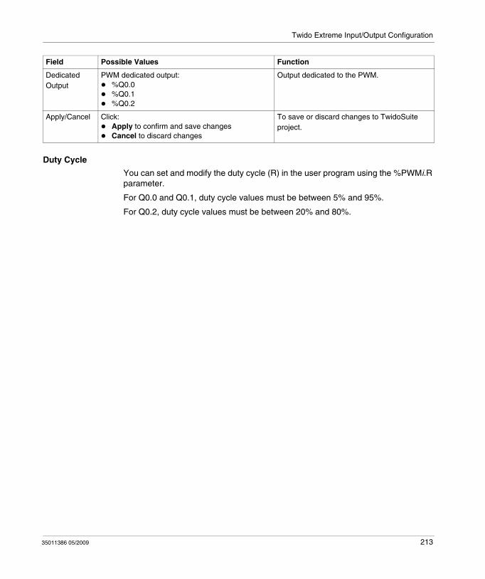
Twido Extreme Input/Output Configuration
Duty Cycle
You can set and modify the duty cycle (R) in the user program using the %PWMi.R parameter.
For Q0.0 and Q0.1, duty cycle values must be between 5% and 95%.
For Q0.2, duty cycle values must be between 20% and 80%.
Dedicated Output
PWM dedicated output:%Q0.0%Q0.1%Q0.2
Output dedicated to the PWM.
Apply/Cancel Click:Apply to confirm and save changesCancel to discard changes
To save or discard changes to TwidoSuite project.
Field Possible Values Function
35011386 05/2009 213
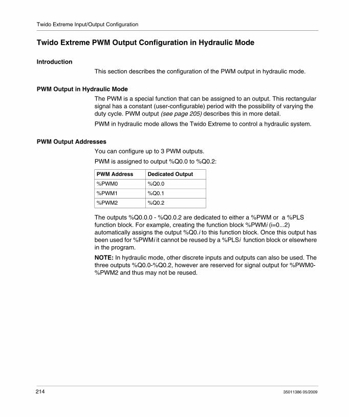
Twido Extreme Input/Output Configuration
Twido Extreme PWM Output Configuration in Hydraulic Mode
Introduction
This section describes the configuration of the PWM output in hydraulic mode.
PWM Output in Hydraulic Mode
The PWM is a special function that can be assigned to an output. This rectangular signal has a constant (user-configurable) period with the possibility of varying the duty cycle. PWM output (see page 205) describes this in more detail.
PWM in hydraulic mode allows the Twido Extreme to control a hydraulic system.
PWM Output Addresses
You can configure up to 3 PWM outputs.
PWM is assigned to output %Q0.0 to %Q0.2:
The outputs %Q0.0.0 - %Q0.0.2 are dedicated to either a %PWM or a %PLS function block. For example, creating the function block %PWMi (i=0...2) automatically assigns the output %Q0.i to this function block. Once this output has been used for %PWMi it cannot be reused by a %PLSi function block or elsewhere in the program.
NOTE: In hydraulic mode, other discrete inputs and outputs can also be used. The three outputs %Q0.0-%Q0.2, however are reserved for signal output for %PWM0-%PWM2 and thus may not be reused.
PWM Address Dedicated Output
%PWM0 %Q0.0
%PWM1 %Q0.1
%PWM2 %Q0.2
214 35011386 05/2009
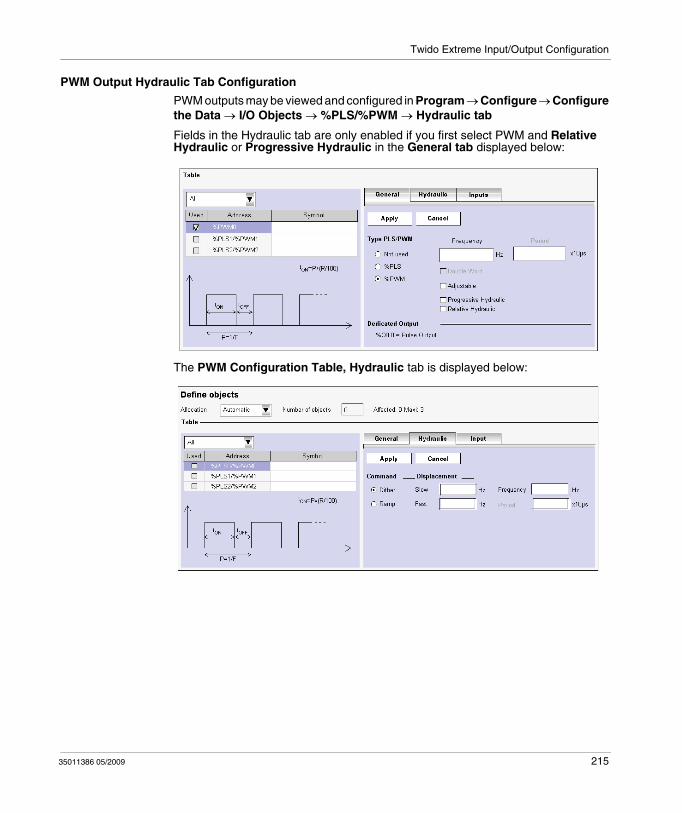
Twido Extreme Input/Output Configuration
PWM Output Hydraulic Tab Configuration
PWM outputs may be viewed and configured in Program → Configure → Configure the Data → I/O Objects → %PLS/%PWM → Hydraulic tab
Fields in the Hydraulic tab are only enabled if you first select PWM and Relative Hydraulic or Progressive Hydraulic in the General tab displayed below:
The PWM Configuration Table, Hydraulic tab is displayed below:
35011386 05/2009 215
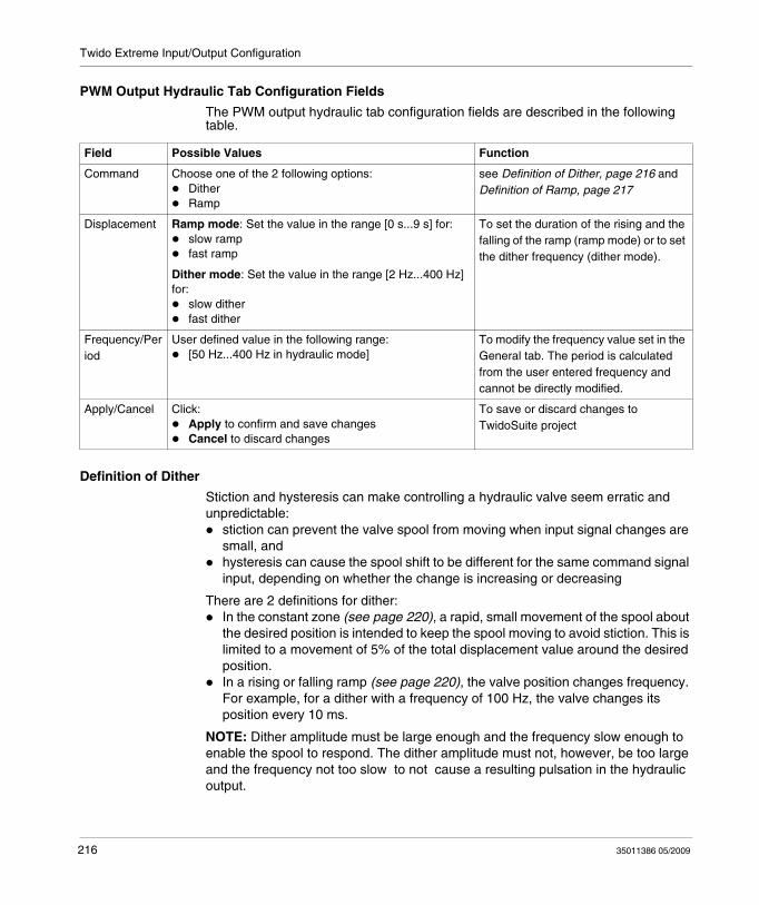
Twido Extreme Input/Output Configuration
PWM Output Hydraulic Tab Configuration Fields
The PWM output hydraulic tab configuration fields are described in the following table.
Definition of Dither
Stiction and hysteresis can make controlling a hydraulic valve seem erratic and unpredictable:
stiction can prevent the valve spool from moving when input signal changes are small, andhysteresis can cause the spool shift to be different for the same command signal input, depending on whether the change is increasing or decreasing
There are 2 definitions for dither:In the constant zone (see page 220), a rapid, small movement of the spool about the desired position is intended to keep the spool moving to avoid stiction. This is limited to a movement of 5% of the total displacement value around the desired position.In a rising or falling ramp (see page 220), the valve position changes frequency. For example, for a dither with a frequency of 100 Hz, the valve changes its position every 10 ms.
NOTE: Dither amplitude must be large enough and the frequency slow enough to enable the spool to respond. The dither amplitude must not, however, be too large and the frequency not too slow to not cause a resulting pulsation in the hydraulic output.
Field Possible Values Function
Command Choose one of the 2 following options:DitherRamp
see Definition of Dither, page 216 and Definition of Ramp, page 217
Displacement Ramp mode: Set the value in the range [0 s...9 s] for:slow ramp fast ramp
Dither mode: Set the value in the range [2 Hz...400 Hz] for:
slow dither fast dither
To set the duration of the rising and the falling of the ramp (ramp mode) or to set the dither frequency (dither mode).
Frequency/Period
User defined value in the following range:[50 Hz...400 Hz in hydraulic mode]
To modify the frequency value set in the General tab. The period is calculated from the user entered frequency and cannot be directly modified.
Apply/Cancel Click:Apply to confirm and save changesCancel to discard changes
To save or discard changes to TwidoSuite project
216 35011386 05/2009
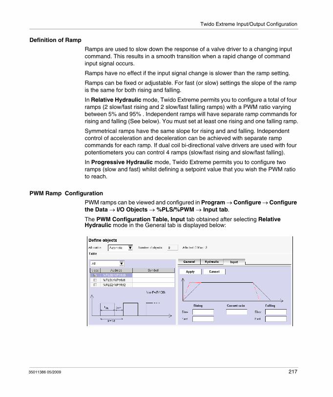
Twido Extreme Input/Output Configuration
Definition of Ramp
Ramps are used to slow down the response of a valve driver to a changing input command. This results in a smooth transition when a rapid change of command input signal occurs.
Ramps have no effect if the input signal change is slower than the ramp setting.
Ramps can be fixed or adjustable. For fast (or slow) settings the slope of the ramp is the same for both rising and falling.
In Relative Hydraulic mode, Twido Extreme permits you to configure a total of four ramps (2 slow/fast rising and 2 slow/fast falling ramps) with a PWM ratio varying between 5% and 95% . Independent ramps will have separate ramp commands for rising and falling (See below). You must set at least one rising and one falling ramp.
Symmetrical ramps have the same slope for rising and and falling. Independent control of acceleration and deceleration can be achieved with separate ramp commands for each ramp. If dual coil bi-directional valve drivers are used with four potentiometers you can control 4 ramps (slow/fast rising and slow/fast falling).
In Progressive Hydraulic mode, Twido Extreme permits you to configure two ramps (slow and fast) whilst defining a setpoint value that you wish the PWM ratio to reach.
PWM Ramp Configuration
PWM ramps can be viewed and configured in Program → Configure → Configure the Data → I/O Objects → %PLS/%PWM → Input tab.
The PWM Configuration Table, Input tab obtained after selecting Relative Hydraulic mode in the General tab is displayed below:
35011386 05/2009 217
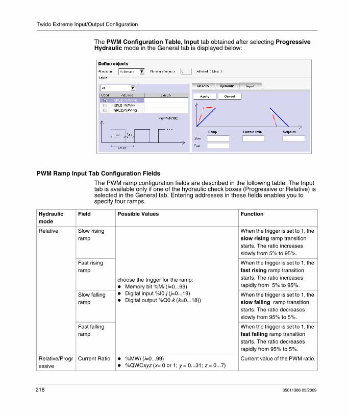
Twido Extreme Input/Output Configuration
The PWM Configuration Table, Input tab obtained after selecting Progressive Hydraulic mode in the General tab is displayed below:
PWM Ramp Input Tab Configuration Fields
The PWM ramp configuration fields are described in the following table. The Input tab is available only if one of the hydraulic check boxes (Progressive or Relative) is selected in the General tab. Entering addresses in these fields enables you to specify four ramps.
Hydraulic mode
Field Possible Values Function
Relative Slow rising ramp
choose the trigger for the ramp:Memory bit %Mi (i=0...99)Digital input %I0.j (j=0...19)Digital output %Q0.k (k=0...18))
When the trigger is set to 1, the slow rising ramp transition starts. The ratio increases slowly from 5% to 95%.
Fast rising ramp
When the trigger is set to 1, the fast rising ramp transition starts. The ratio increases rapidly from 5% to 95%.
Slow falling ramp
When the trigger is set to 1, the slow falling ramp transition starts. The ratio decreases slowly from 95% to 5%.
Fast falling ramp
When the trigger is set to 1, the fast falling ramp transition starts. The ratio decreases rapidly from 95% to 5%.
Relative/Progressive
Current Ratio %MWi (i=0...99) %QWCxyz (x= 0 or 1; y = 0...31; z = 0...7)
Current value of the PWM ratio.
218 35011386 05/2009
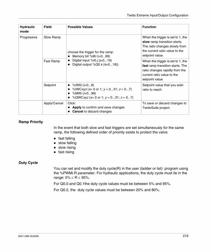
Twido Extreme Input/Output Configuration
Ramp Priority
In the event that both slow and fast triggers are set simultaneously for the same ramp, the following defined order of prioirity exists to protect the valve:
fast fallingslow fallingslow risingfast rising
Duty Cycle
You can set and modify the duty cycle(R) in the user (ladder or list) program using the %PWMi.R parameter. For hydraulic applications, the duty cycle must lie in the range: 5% ≤ R ≤ 95%.
For Q0.0 and Q0.1the duty cycle values must be between 5% and 95%.
For Q0.2, the duty cycle values must be between 20% and 80%.
Progressive Slow Ramp
choose the trigger for the ramp:Memory bit %Mi (i=0...99)Digital input %I0.j (j=0...19)Digital output %Q0.k (k=0...18))
When the trigger is set to 1, the slow ramp transition starts. The ratio changes slowly from the current ratio value to the setpoint value.
Fast Ramp When the trigger is set to 1, the fast ramp transition starts. The ratio changes rapidly from the current ratio value to the setpoint value.
Setpoint %IW0i (i=0...8)%IWCxyz (x= 0 or 1; y = 0...31; z = 0...7)%MWi (i=0...99)%QWCxyz (x= 0 or 1; y = 0...31; z = 0...7)
Setpoint value that you wish ratio to reach.
Apply/Cancel Click:Apply to confirm and save changesCancel to discard changes
To save or discard changes to TwidoSuite project.
Hydraulic mode
Field Possible Values Function
35011386 05/2009 219
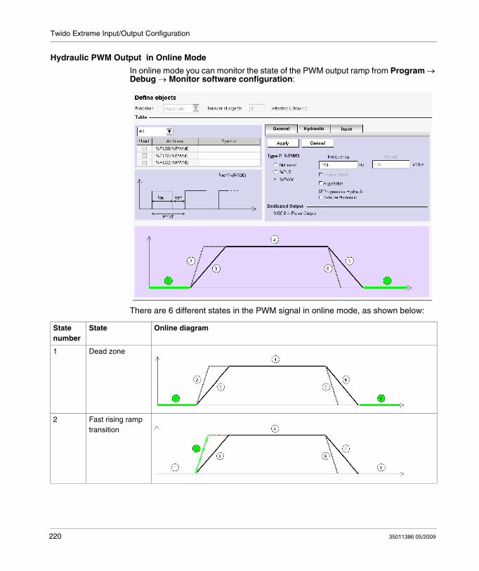
Twido Extreme Input/Output Configuration
Hydraulic PWM Output in Online Mode
In online mode you can monitor the state of the PWM output ramp from Program → Debug → Monitor software configuration:
There are 6 different states in the PWM signal in online mode, as shown below:
State number
State Online diagram
1 Dead zone
2 Fast rising ramp transition
220 35011386 05/2009
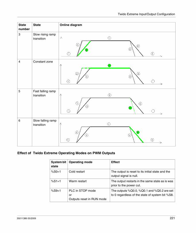
Twido Extreme Input/Output Configuration
Effect of Twido Extreme Operating Modes on PWM Outputs
3 Slow rising ramp transition
4 Constant zone
5 Fast falling ramp transition
6 Slow falling ramp transition
State number
State Online diagram
System bit state
Operating mode Effect
%S0=1 Cold restart The output is reset to its initial state and the output signal is null.
%S1=1 Warm restart The output restarts in the same state as is was prior to the power cut.
%S9=1 PLC in STOP modeorOutputs reset in RUN mode
The outputs %Q0.0, %Q0.1 and %Q0.2 are set to 0 regardless of the state of system bit %S8.
35011386 05/2009 221
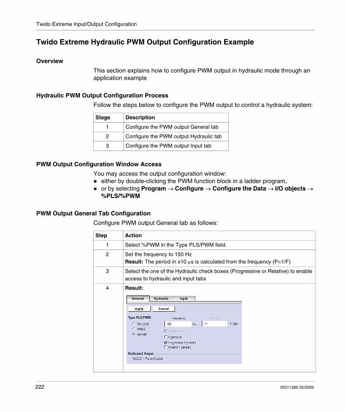
Twido Extreme Input/Output Configuration
Twido Extreme Hydraulic PWM Output Configuration Example
Overview
This section explains how to configure PWM output in hydraulic mode through an application example
Hydraulic PWM Output Configuration Process
Follow the steps below to configure the PWM output to control a hydraulic system:
PWM Output Configuration Window Access
You may access the output configuration window:either by double-clicking the PWM function block in a ladder program,or by selecting Program → Configure → Configure the Data → I/O objects → %PLS/%PWM
PWM Output General Tab Configuration
Configure PWM output General tab as follows:
Stage Description
1 Configure the PWM output General tab
2 Configure the PWM output Hydraulic tab
3 Configure the PWM output Input tab
Step Action
1 Select %PWM in the Type PLS/PWM field.
2 Set the frequency to 150 HzResult: The period in x10 μs is calculated from the frequency (P=1/F)
3 Select the one of the Hydraulic check boxes (Progressive or Relative) to enable access to hydraulic and input tabs
4 Result:
222 35011386 05/2009
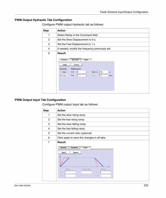
Twido Extreme Input/Output Configuration
PWM Output Hydraulic Tab Configuration
Configure PWM output Hydraulic tab as follows:
PWM Output Input Tab Configuration
Configure PWM output Input tab as follows:
Step Action
1 Select Ramp in the Command field.
2 Set the Slow Displacement to 6 s.
3 Set the Fast Displacement to 1 s.
4 If needed, modify the frequency previously set.
5 Result:
Step Action
1 Set the slow rising ramp.
2 Set the fast rising ramp.
3 Set the slow falling ramp.
4 Set the fast falling ramp.
5 Set the current ratio (optional)
6 Click apply to save the changes in all tabs.
7 Result:
35011386 05/2009 223

Twido Extreme Input/Output Configuration
224 35011386 05/2009
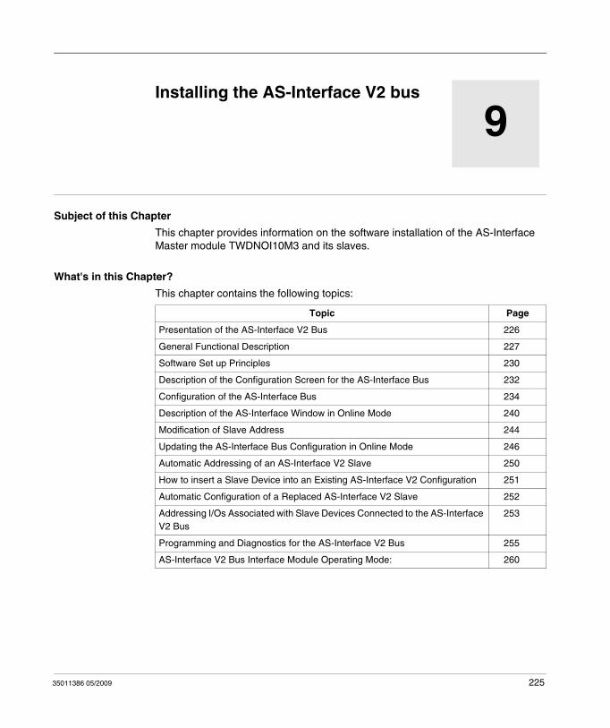
35011386 05/2009
9
Installing the AS-Interface bus
35011386 05/2009
Installing the AS-Interface V2 bus
Subject of this Chapter
This chapter provides information on the software installation of the AS-Interface Master module TWDNOI10M3 and its slaves.
What's in this Chapter?
This chapter contains the following topics:
Topic Page
Presentation of the AS-Interface V2 Bus 226
General Functional Description 227
Software Set up Principles 230
Description of the Configuration Screen for the AS-Interface Bus 232
Configuration of the AS-Interface Bus 234
Description of the AS-Interface Window in Online Mode 240
Modification of Slave Address 244
Updating the AS-Interface Bus Configuration in Online Mode 246
Automatic Addressing of an AS-Interface V2 Slave 250
How to insert a Slave Device into an Existing AS-Interface V2 Configuration 251
Automatic Configuration of a Replaced AS-Interface V2 Slave 252
Addressing I/Os Associated with Slave Devices Connected to the AS-Interface V2 Bus
253
Programming and Diagnostics for the AS-Interface V2 Bus 255
AS-Interface V2 Bus Interface Module Operating Mode: 260
225
Installing the AS-Interface bus
Presentation of the AS-Interface V2 Bus
Introduction
The AS-Interface Bus (Actuator Sensor-Interface) allows the interconnection on a single cable of sensor devices/actuators at the lowest level of automation.
These sensors/actuators will be defined in the documentation as slave devices.
To implement the AS-Interface application you need to define the physical context of the application into which it will integrated (expansion bus, supply, processor, modules, AS-Interface slave devices connected to the bus) then ensure its software implementation.
This second aspect will be carried out from the different TwidoSuite editors:
either in local mode,or in online mode.
AS-Interface V2 Bus
The AS-interface Master module TWDNOI10M3 includes the following functionalities:
M3 profile: This profile includes all the functionalities defined by the AS-Interface V2 standard, but does not support the S7-4 analog profilesOne AS-Interface channel per moduleAutomatic addressing for the slave with the address 0Management of profiles and parametersProtection from polarity reversion on the bus inputs
The AS-Interface bus then allows:
Up to 31 standard address and 62 extended address slavesUp to 248 inputs and 186 outputsUp to 7 analog slaves (Max of four I/0 per slave)A cycle time of 10 ms maximum
A maximum of 2 AS-Interface Master modules can be connected to a Twido modular controller, a TWDLC•A24DRF or a TWDLC••40DRFcompact controller.
226 35011386 05/2009
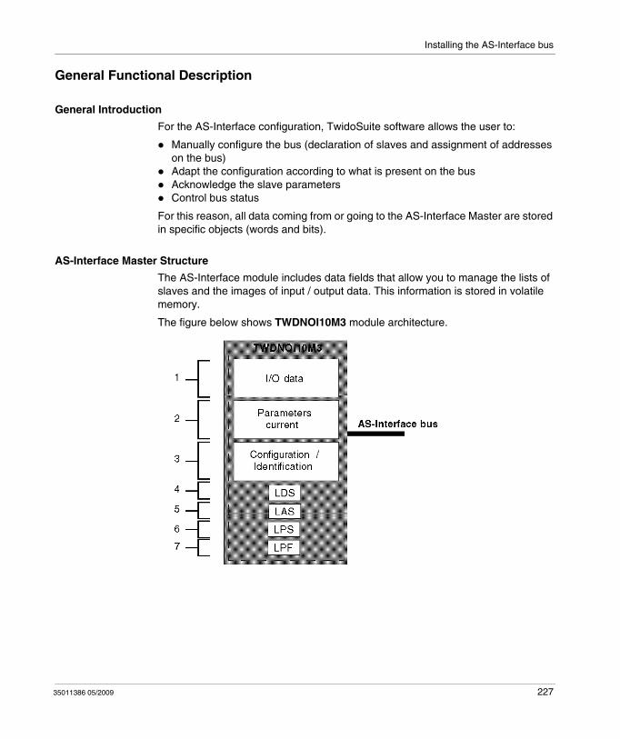
Installing the AS-Interface bus
General Functional Description
General Introduction
For the AS-Interface configuration, TwidoSuite software allows the user to:
Manually configure the bus (declaration of slaves and assignment of addresses on the bus)Adapt the configuration according to what is present on the busAcknowledge the slave parametersControl bus status
For this reason, all data coming from or going to the AS-Interface Master are stored in specific objects (words and bits).
AS-Interface Master Structure
The AS-Interface module includes data fields that allow you to manage the lists of slaves and the images of input / output data. This information is stored in volatile memory.
The figure below shows TWDNOI10M3 module architecture.
35011386 05/2009 227
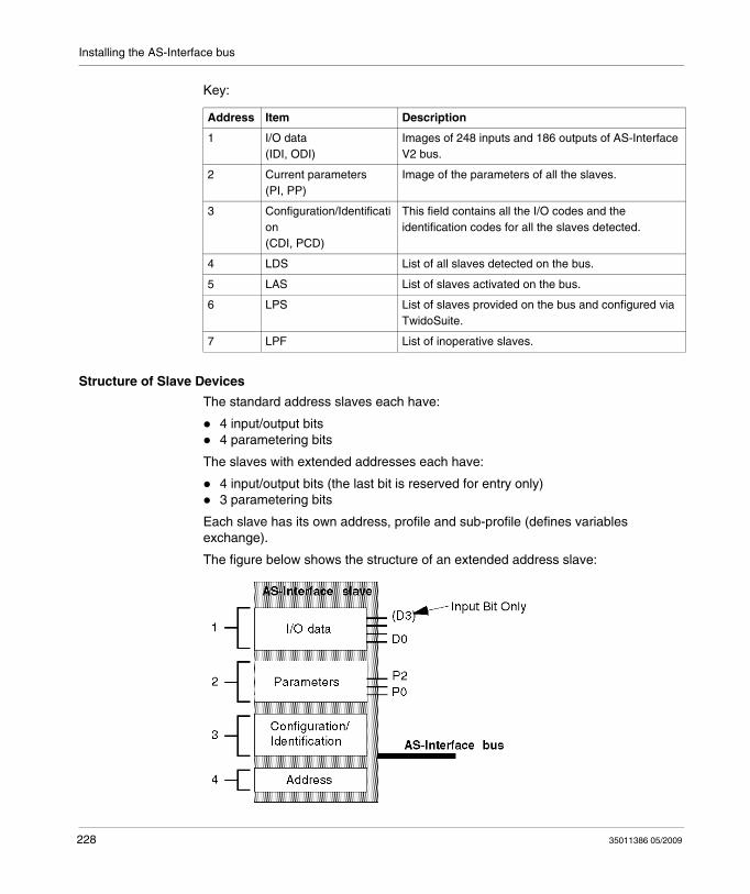
Installing the AS-Interface bus
Key:
Structure of Slave Devices
The standard address slaves each have:
4 input/output bits4 parametering bits
The slaves with extended addresses each have:
4 input/output bits (the last bit is reserved for entry only)3 parametering bits
Each slave has its own address, profile and sub-profile (defines variables exchange).
The figure below shows the structure of an extended address slave:
Address Item Description
1 I/O data(IDI, ODI)
Images of 248 inputs and 186 outputs of AS-Interface V2 bus.
2 Current parameters(PI, PP)
Image of the parameters of all the slaves.
3 Configuration/Identification(CDI, PCD)
This field contains all the I/O codes and the identification codes for all the slaves detected.
4 LDS List of all slaves detected on the bus.
5 LAS List of slaves activated on the bus.
6 LPS List of slaves provided on the bus and configured via TwidoSuite.
7 LPF List of inoperative slaves.
228 35011386 05/2009
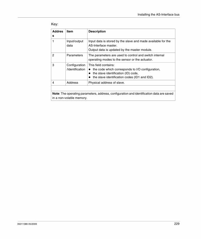
Installing the AS-Interface bus
Key:
Address
Item Description
1 Input/output data
Input data is stored by the slave and made available for the AS-Interface master.Output data is updated by the master module.
2 Parameters The parameters are used to control and switch internal operating modes to the sensor or the actuator.
3 Configuration/Identification
This field contains:the code which corresponds to I/O configuration,the slave identification (ID) code,the slave identification codes (ID1 and ID2).
4 Address Physical address of slave.
Note: The operating parameters, address, configuration and identification data are saved in a non-volatile memory.
35011386 05/2009 229
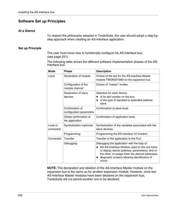
Installing the AS-Interface bus
Software Set up Principles
At a Glance
To respect the philosophy adopted in TwidoSuite, the user should adopt a step-by-step approach when creating an AS-Interface application.
Set up Principle
The user must know how to functionally configure his AS-Interface bus (see page 251).
The following table shows the different software implementation phases of the AS-Interface bus.
NOTE: The declaration and deletion of the AS-Interface Master module on the expansion bus is the same as for another expansion module. However, once two AS-Interface Master modules have been declared on the expansion bus, TwidoSuite will not permit another one to be declared.
Mode Phase Description
Local Declaration of module Choice of the slot for the AS-Interface Master module TWDNOI10M3 on the expansion bus.
Configuration of the module channel
Choice of "master" modes.
Declaration of slave devices
Selection for each device:of its slot number on the bus,of the type of standard or extended address slave.
Confirmation of configuration parameters
Confirmation at slave level.
Global confirmation of the application
Confirmation of application level.
Local or connected
Symbolization (optional) Symbolization of the variables associated with the slave devices.
Programming Programming the AS-Interface V2 function.
Connected Transfer Transfer of the application to the PLC.
Debugging Debugging the application with the help of:the AS-Interface Window used on the one hand to display slaves (address, parameters), and on the other, to assign them the desired addressesdiagnostic screens allowing identification of errors.
230 35011386 05/2009

Installing the AS-Interface bus
Precautions Prior to Connection
Before connecting (via the software) the PC to the controller and to avoid any detection problem:
Ensure that no slave is physically present on the bus with address 0Ensure that 2 slaves are not physically present with the same address.
35011386 05/2009 231
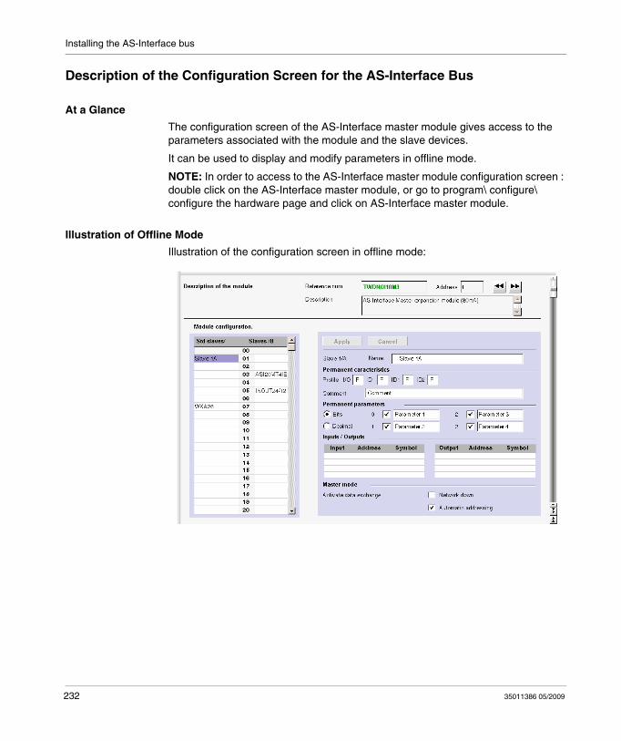
Installing the AS-Interface bus
Description of the Configuration Screen for the AS-Interface Bus
At a Glance
The configuration screen of the AS-Interface master module gives access to the parameters associated with the module and the slave devices.
It can be used to display and modify parameters in offline mode.
NOTE: In order to access to the AS-Interface master module configuration screen : double click on the AS-Interface master module, or go to program\ configure\ configure the hardware page and click on AS-Interface master module.
Illustration of Offline Mode
Illustration of the configuration screen in offline mode:
232 35011386 05/2009
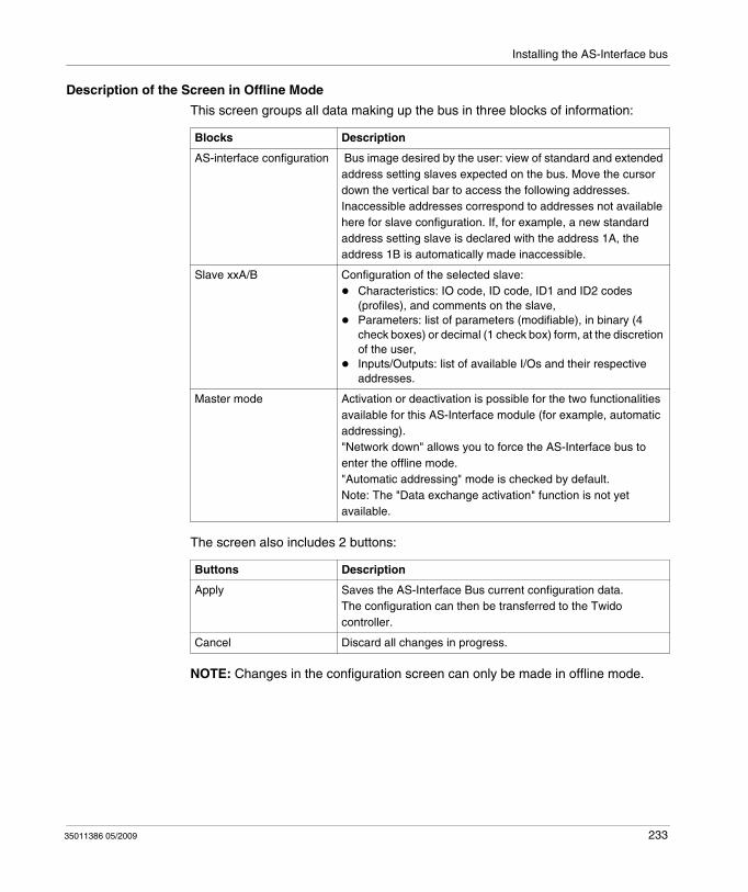
Installing the AS-Interface bus
Description of the Screen in Offline Mode
This screen groups all data making up the bus in three blocks of information:
The screen also includes 2 buttons:
NOTE: Changes in the configuration screen can only be made in offline mode.
Blocks Description
AS-interface configuration Bus image desired by the user: view of standard and extended address setting slaves expected on the bus. Move the cursor down the vertical bar to access the following addresses.Inaccessible addresses correspond to addresses not available here for slave configuration. If, for example, a new standard address setting slave is declared with the address 1A, the address 1B is automatically made inaccessible.
Slave xxA/B Configuration of the selected slave: Characteristics: IO code, ID code, ID1 and ID2 codes (profiles), and comments on the slave,Parameters: list of parameters (modifiable), in binary (4 check boxes) or decimal (1 check box) form, at the discretion of the user, Inputs/Outputs: list of available I/Os and their respective addresses.
Master mode Activation or deactivation is possible for the two functionalities available for this AS-Interface module (for example, automatic addressing)."Network down" allows you to force the AS-Interface bus to enter the offline mode. "Automatic addressing" mode is checked by default. Note: The "Data exchange activation" function is not yet available.
Buttons Description
Apply Saves the AS-Interface Bus current configuration data.The configuration can then be transferred to the Twido controller.
Cancel Discard all changes in progress.
35011386 05/2009 233
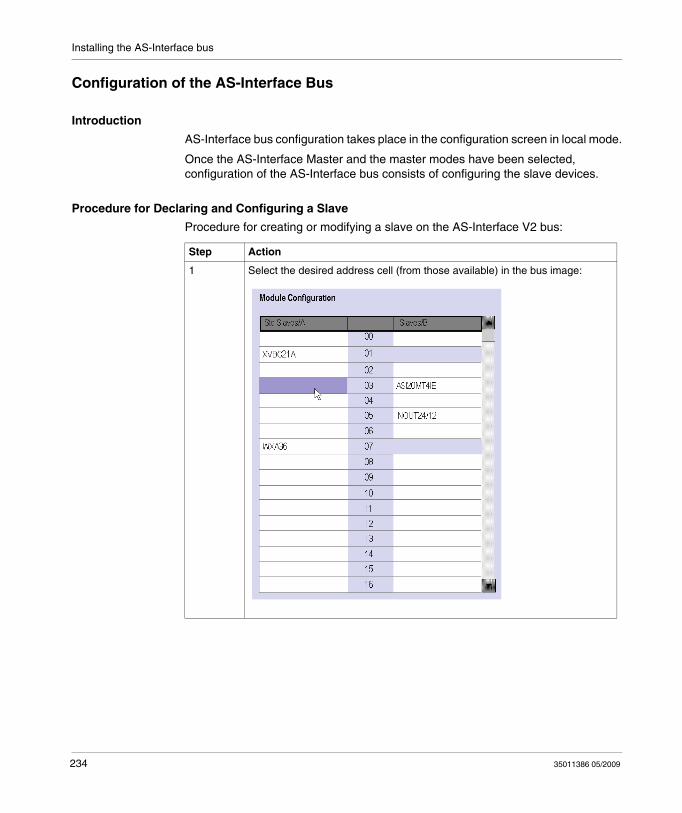
Installing the AS-Interface bus
Configuration of the AS-Interface Bus
Introduction
AS-Interface bus configuration takes place in the configuration screen in local mode.
Once the AS-Interface Master and the master modes have been selected, configuration of the AS-Interface bus consists of configuring the slave devices.
Procedure for Declaring and Configuring a Slave
Procedure for creating or modifying a slave on the AS-Interface V2 bus:
Step Action
1 Select the desired address cell (from those available) in the bus image:
234 35011386 05/2009
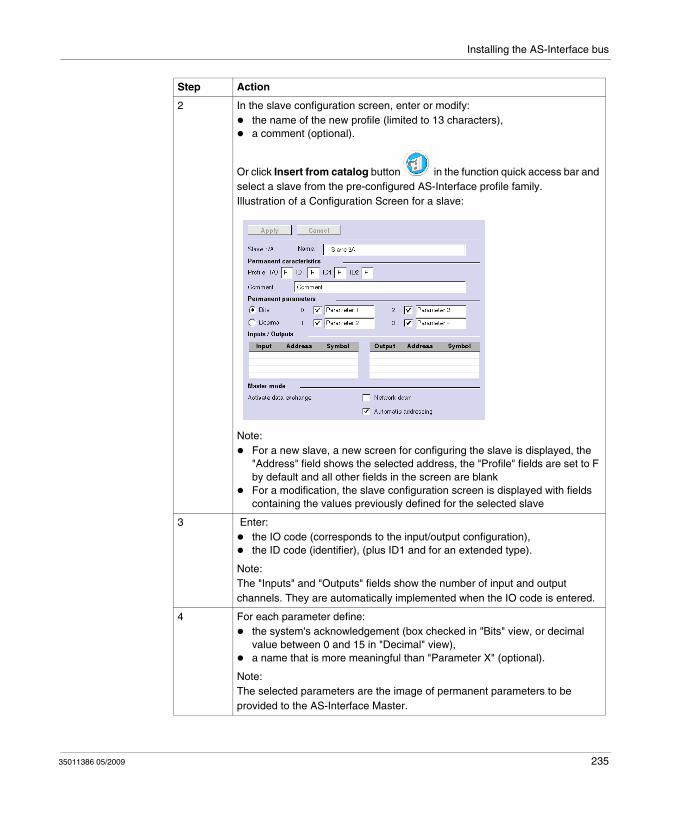
Installing the AS-Interface bus
2 In the slave configuration screen, enter or modify: the name of the new profile (limited to 13 characters),a comment (optional).
Or click Insert from catalog button in the function quick access bar and select a slave from the pre-configured AS-Interface profile family.Illustration of a Configuration Screen for a slave:
Note:For a new slave, a new screen for configuring the slave is displayed, the "Address" field shows the selected address, the "Profile" fields are set to F by default and all other fields in the screen are blankFor a modification, the slave configuration screen is displayed with fields containing the values previously defined for the selected slave
3 Enter: the IO code (corresponds to the input/output configuration),the ID code (identifier), (plus ID1 and for an extended type).
Note: The "Inputs" and "Outputs" fields show the number of input and output channels. They are automatically implemented when the IO code is entered.
4 For each parameter define: the system's acknowledgement (box checked in "Bits" view, or decimal value between 0 and 15 in "Decimal" view),a name that is more meaningful than "Parameter X" (optional).
Note: The selected parameters are the image of permanent parameters to be provided to the AS-Interface Master.
Step Action
35011386 05/2009 235
Installing the AS-Interface bus
NOTE: The software limits the number of analog slave declarations to 7.
NOTE: About the Schneider AS-Interface catalog: when you click Insert from catalog, you can create and configure slaves in "Private family" (other than those in the Schneider AS-Interface catalog.
5 If needed, modify "Address" (within the limit of available addresses on the bus), by clicking the up/down arrows to the left of the address (access is then given to authorized addresses) or by entering the address using the keyboard.
6 Confirm the slave configuration by clicking on the Apply button.The result is the check that:
the IO and ID are authorized,the slave address is authorized (if keyboard entry is used) according to the ID code ("bank" /B slaves are only available if the ID code is equal to A).
If a detected error occurs, an error message warns the user (for example: "The slave cannot have this address") and the screen is displayed again with the initial values (in the profile or address, depending on the condition itself).
Step Action
236 35011386 05/2009
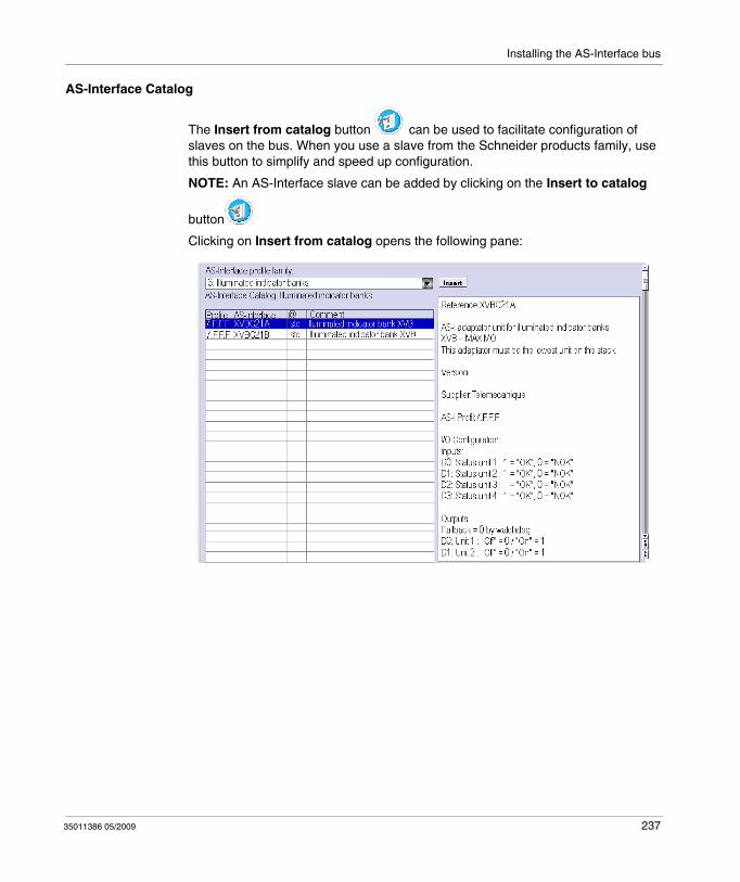
Installing the AS-Interface bus
AS-Interface Catalog
The Insert from catalog button can be used to facilitate configuration of slaves on the bus. When you use a slave from the Schneider products family, use this button to simplify and speed up configuration.
NOTE: An AS-Interface slave can be added by clicking on the Insert to catalog
button
Clicking on Insert from catalog opens the following pane:
35011386 05/2009 237
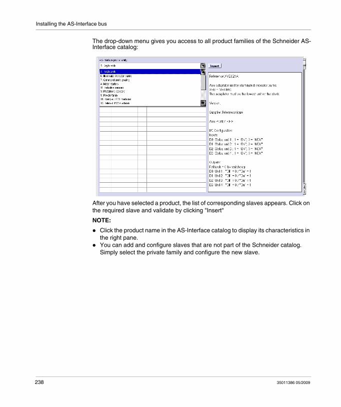
Installing the AS-Interface bus
The drop-down menu gives you access to all product families of the Schneider AS-Interface catalog:
After you have selected a product, the list of corresponding slaves appears. Click on the required slave and validate by clicking "Insert"
NOTE:
Click the product name in the AS-Interface catalog to display its characteristics in the right pane.You can add and configure slaves that are not part of the Schneider catalog. Simply select the private family and configure the new slave.
238 35011386 05/2009
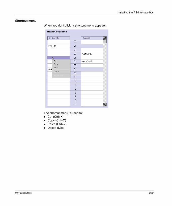
Installing the AS-Interface bus
Shortcut menu
When you right click, a shortcut menu appears:
The shorcut menu is used to:Cut (Ctrl+X)Copy (Ctrl+C)Paste (Ctrl+V)Delete (Del)
35011386 05/2009 239
Installing the AS-Interface bus
Description of the AS-Interface Window in Online Mode
At a Glance
When the PC is connected to the controller (after uploading the application to the controller), the AS-Interface Window displays online features.
In online mode, the AS-Interface Window dynamically provides an image of the physical bus that includes the:
List of expected slaves (entered) during configuration with their name, and the list of detected slaves (with unknown names, but otherwise expected),Status of the AS-Interface module and the slave devices,Image of the profile, parameters and input/output values of the selected slaves.
It also enables the user:
To obtain diagnostics of the slaves on which an error is detected (see page 243),To modify the address of a slave in online mode (see page 244),To transmit the image of the slaves to the configuration screen (see page 246),To address all the slaves with the desired addresses (during the first debugging).
240 35011386 05/2009
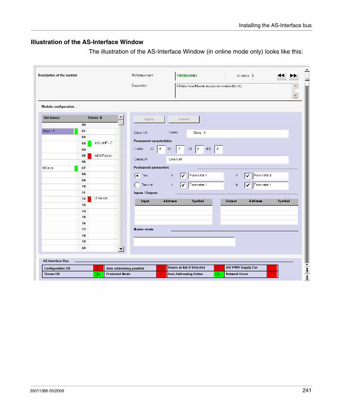
Installing the AS-Interface bus
Illustration of the AS-Interface Window
The illustration of the AS-Interface Window (in online mode only) looks like this:
35011386 05/2009 241
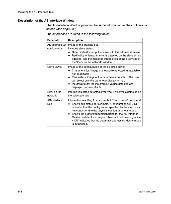
Installing the AS-Interface bus
Description of the AS-Interface Window
The AS-Interface Window provides the same information as the configuration screen (see page 233).
The differences are listed in the following table:
Schedule Description
AS-interface V2 configuration
Image of the physical bus.Includes slave status:
Green indicator lamp: the slave with this address is active.Red indicator lamp: an error is detected on the slave at this address, and the message informs you of the error type in the "Error on the network" window.
Slave xxA/B Image of the configuration of the selected slave: Characteristics: image of the profile detected (unavailable, non-modifiable),Parameters: image of the parameters detected. The user can select only the parameter display format, Inputs/Outputs: the input/output values detected are displayed,non-modifiable.
Error on the network
Informs you of the detected error type, if an error is detected on the selected slave.
AS-Interface Bus
Information resulting from an implicit "Read Status" command.Shows bus status: for example, "Configuration OK = OFF" indicates that the configuration specified by the user does not correspond to the physical configuration of the bus,Shows the authorized functionalities for the AS-Interface Master module: for example, "Automatic addressing active = ON" indicates that the automatic addressing Master mode is authorized.
242 35011386 05/2009
Installing the AS-Interface bus
Displaying Slave Status
When the indicator lamp associated with an address is red, there is an error detected on the slave associated with this address. The "Error on the network" window then provides the diagnostics of the selected slave.
Description of errors:
The profile specified by the user by the configuration of a given address does not correspond to the actual profile detected for this address on the bus (diagnostics: "Profile error"),A new slave, not specified at configuration, is detected on the bus: a red indicator lamp is then displayed for this address and the slave name displayed is "Unknown" (diagnostics: "Slave not projected"),Peripheral inoperative, if the slave detected supports it (diagnostics: "Peripheral inoperative"),A configured profile is specified but no slave is detected for this address on the bus (diagnostics: "Slave not detected").
35011386 05/2009 243
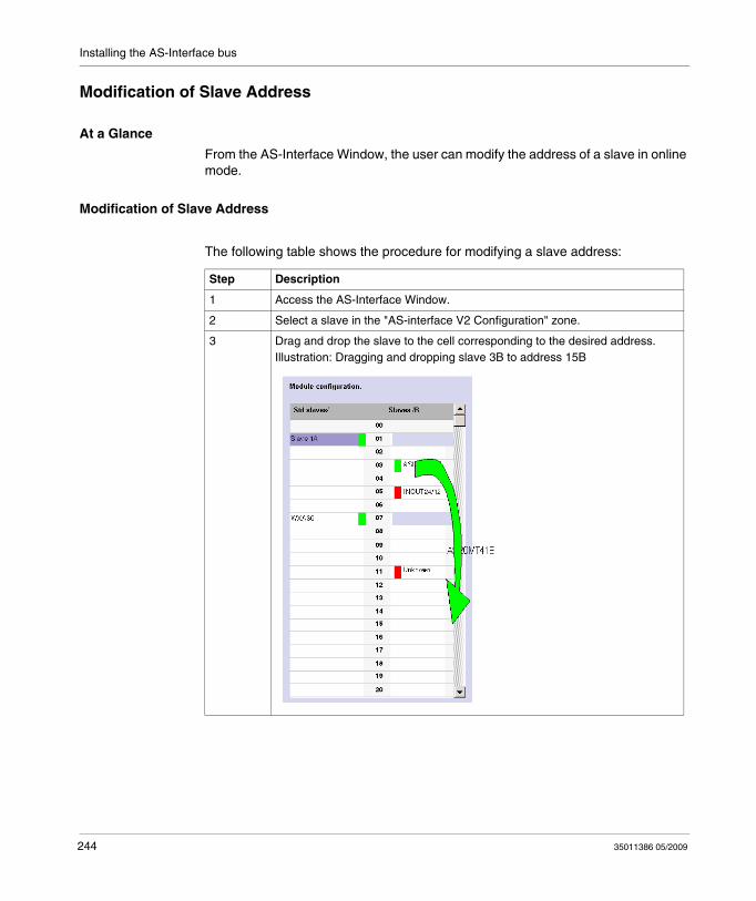
Installing the AS-Interface bus
Modification of Slave Address
At a Glance
From the AS-Interface Window, the user can modify the address of a slave in online mode.
Modification of Slave Address
The following table shows the procedure for modifying a slave address:
Step Description
1 Access the AS-Interface Window.
2 Select a slave in the "AS-interface V2 Configuration" zone.
3 Drag and drop the slave to the cell corresponding to the desired address.Illustration: Dragging and dropping slave 3B to address 15B
244 35011386 05/2009
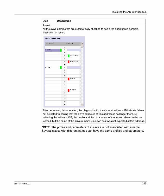
Installing the AS-Interface bus
NOTE: The profile and parameters of a slave are not associated with a name. Several slaves with different names can have the same profiles and parameters.
Result: All the slave parameters are automatically checked to see if the operation is possible.Illustration of result:
After performing this operation, the diagnostics for the slave at address 3B indicate "slave not detected" meaning that the slave expected at this address is no longer there. By selecting the address 15B, the profile and the parameters of the moved slave can be re-located, but the name of the slave remains unknown as it was not expected at this address.
Step Description
35011386 05/2009 245
Installing the AS-Interface bus
Updating the AS-Interface Bus Configuration in Online Mode
At a Glance
In online mode, no modification of the configuration screen is authorized and the physical configuration and software configuration can be different. Any difference in profile or parameters for a configured or non-configured slave can be taken into account in the configuration screen; in fact, it is possible to transmit any modification to the configuration screen before transferring the new application to the controller.
The procedure to follow in order to take the physical configuration into account is the following:
Transfer of a Slave Image to the Configuration Screen.
In the case when a slave that is not specified in the configuration is detected on the bus, an "Unknown" slave appears in the "AS-interface V2 Configuration zone" of the AS-Interface window for the detected address.
The following table describes the procedure for transferring the image of the "Unknown" slave to the configuration screen:
Step Description
1 Transfer of the desired slave configuration to the configuration screen.
2 Acceptance of the configuration in the configuration screen.
3 Confirmation of the new configuration.
4 Transfer of the application to the module.
Step Description
1 Access the AS-Interface window.
2 Select the desired slave in the "AS-interface V2 Configuration" zone.
246 35011386 05/2009
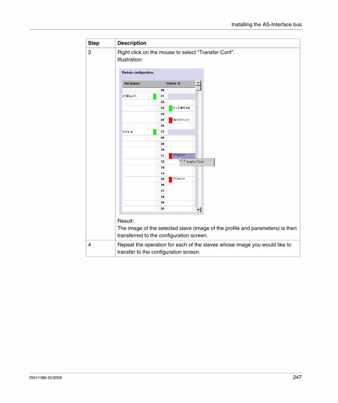
Installing the AS-Interface bus
3 Right click on the mouse to select "Transfer Conf".Illustration:
Result: The image of the selected slave (image of the profile and parameters) is then transferred to the configuration screen.
4 Repeat the operation for each of the slaves whose image you would like to transfer to the configuration screen.
Step Description
35011386 05/2009 247
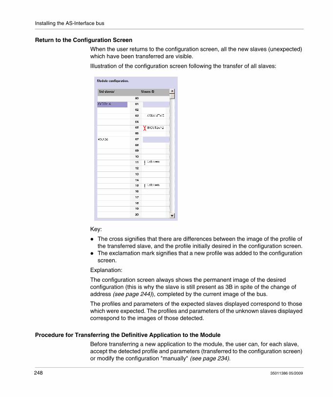
Installing the AS-Interface bus
Return to the Configuration Screen
When the user returns to the configuration screen, all the new slaves (unexpected) which have been transferred are visible.
Illustration of the configuration screen following the transfer of all slaves:
Key:
The cross signifies that there are differences between the image of the profile of the transferred slave, and the profile initially desired in the configuration screen.The exclamation mark signifies that a new profile was added to the configuration screen.
Explanation:
The configuration screen always shows the permanent image of the desired configuration (this is why the slave is still present as 3B in spite of the change of address (see page 244)), completed by the current image of the bus.
The profiles and parameters of the expected slaves displayed correspond to those which were expected. The profiles and parameters of the unknown slaves displayed correspond to the images of those detected.
Procedure for Transferring the Definitive Application to the Module
Before transferring a new application to the module, the user can, for each slave, accept the detected profile and parameters (transferred to the configuration screen) or modify the configuration "manually" (see page 234).
248 35011386 05/2009
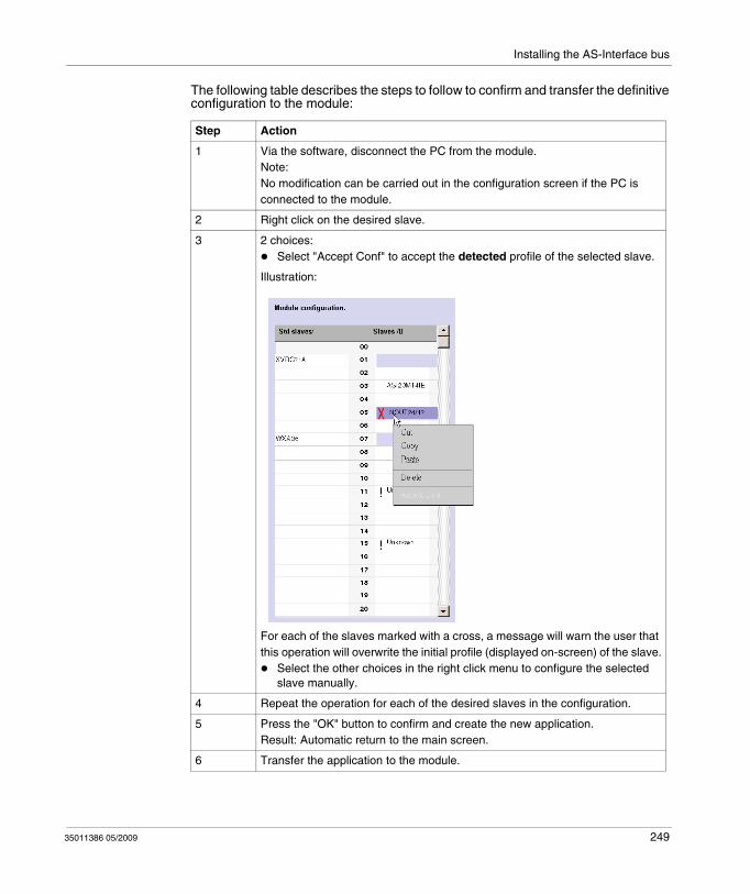
Installing the AS-Interface bus
The following table describes the steps to follow to confirm and transfer the definitive configuration to the module:
Step Action
1 Via the software, disconnect the PC from the module.Note: No modification can be carried out in the configuration screen if the PC is connected to the module.
2 Right click on the desired slave.
3 2 choices: Select "Accept Conf" to accept the detected profile of the selected slave.
Illustration:
For each of the slaves marked with a cross, a message will warn the user that this operation will overwrite the initial profile (displayed on-screen) of the slave.
Select the other choices in the right click menu to configure the selected slave manually.
4 Repeat the operation for each of the desired slaves in the configuration.
5 Press the "OK" button to confirm and create the new application.Result: Automatic return to the main screen.
6 Transfer the application to the module.
35011386 05/2009 249
Installing the AS-Interface bus
Automatic Addressing of an AS-Interface V2 Slave
At a Glance
Each slave on the AS-Interface bus must be assigned (via configuration) a unique physical address. This must be the same as the one declared in TwidoSuite.
TwidoSuite software offers an automatic slave addressing utility so that an AS-Interface console does not have to be used.
The automatic addressing utility is used for:
replacing an inoperative slave,inserting a new slave.
Procedure
The table below shows the procedure for setting the Automatic addressing parameter.
Step Action
1 Access the AS-Interface V2 master module’s configuration screen.
2 Click on the Automatic addressing check box found in the Master mode zone.Result: The Automatic addressing utility will be activated (box checked) or disabled (box not checked. Note: By default, the Automatic addressing parameter has been selected in the configuration screen.
250 35011386 05/2009
Installing the AS-Interface bus
How to insert a Slave Device into an Existing AS-Interface V2 Configuration
At a Glance
It is possible to insert a device into an existing AS-Interface V2 configuration without having to use the pocket programmer.
This operation is possible once:
the Automatic addressing utility of configuration mode is active (see page 250),a single slave is absent in the physical configuration,the slave which is to be inserted is specified in the configuration screen,the slave has the profile expected by the configuration,the slave has the address 0 (A).
The AS-Interface V2 module will therefore automatically assign to the slave the value predefined in the configuration.
Procedure
The following table shows the procedure for making the automatic insertion of a new slave effective.
NOTE: An application can be modified by carrying out the above manipulation as many times as necessary.
Step Action
1 Add the new slave in the configuration screen in local mode.
2 Carry out a configuration transfer to the PLC in connected mode.
3 Physically link the new slave with address 0 (A) to the AS-Interface V2 bus.
35011386 05/2009 251
Installing the AS-Interface bus
Automatic Configuration of a Replaced AS-Interface V2 Slave
Principle
When a slave has been declared inoperative, it can be automatically replaced with a slave of the same type.
This happens without the AS-Interface V2 bus having to stop, and without requiring any manipulation since the configuration mode's Automatic addressing utility is active (see page 250).
Two options are available:
The replacement slave is programmed with the same address using the pocket programmer, and has the same profile and sub-profile as the inoperative slave. It is thus automatically inserted into the list of detected slaves (LDS) and into the list of active slaves (LAS),The replacement slave is blank (address 0 (A), new slave) and has the same profile as the inoperative slave. It will automatically assume the address of the replaced slave, and will then be inserted into the list of detected slaves (LDS) and the list of active slaves (LAS).
252 35011386 05/2009
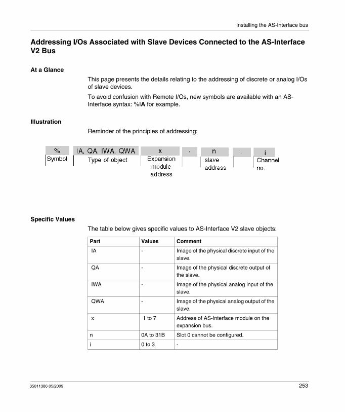
Installing the AS-Interface bus
Addressing I/Os Associated with Slave Devices Connected to the AS-Interface V2 Bus
At a Glance
This page presents the details relating to the addressing of discrete or analog I/Os of slave devices.
To avoid confusion with Remote I/Os, new symbols are available with an AS-Interface syntax: %IA for example.
Illustration
Reminder of the principles of addressing:
Specific Values
The table below gives specific values to AS-Interface V2 slave objects:
Part Values Comment
IA - Image of the physical discrete input of the slave.
QA - Image of the physical discrete output of the slave.
IWA - Image of the physical analog input of the slave.
QWA - Image of the physical analog output of the slave.
x 1 to 7 Address of AS-Interface module on the expansion bus.
n 0A to 31B Slot 0 cannot be configured.
i 0 to 3 -
35011386 05/2009 253
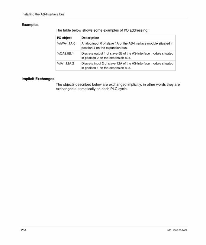
Installing the AS-Interface bus
Examples
The table below shows some examples of I/O addressing:
Implicit Exchanges
The objects described below are exchanged implicitly, in other words they are exchanged automatically on each PLC cycle.
I/O object Description
%IWA4.1A.0 Analog input 0 of slave 1A of the AS-Interface module situated in position 4 on the expansion bus.
%QA2.5B.1 Discrete output 1 of slave 5B of the AS-Interface module situated in position 2 on the expansion bus.
%IA1.12A.2 Discrete input 2 of slave 12A of the AS-Interface module situated in position 1 on the expansion bus.
254 35011386 05/2009
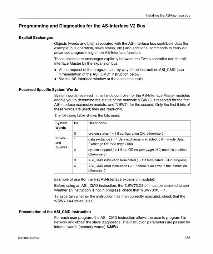
Installing the AS-Interface bus
Programming and Diagnostics for the AS-Interface V2 Bus
Explicit Exchanges
Objects (words and bits) associated with the AS-Interface bus contribute data (for example: bus operation, slave status, etc.) and additional commands to carry out advanced programming of the AS-Interface function.
These objects are exchanged explicitly between the Twido controller and the AS-Interface Master by the expansion bus:
At the request of the program user by way of the instruction: ASI_CMD (see "Presentation of the ASI_CMD" instruction below)Via the AS-Interface window or the animation table.
Reserved Specific System Words
System words reserved in the Twido controller for the AS-Interface Master modules enable you to determine the status of the network: %SW73 is reserved for the first AS-Interface expansion module, and %SW74 for the second. Only the first 5 bits of these words are used; they are read-only.
The following table shows the bits used:
Example of use (for the first AS-Interface expansion module):
Before using an ASI_CMD instruction, the %SW73:X3 bit must be checked to see whether an instruction is not in progress: check that %SW73:X3 = 1.
To ascertain whether the instruction has then correctly executed, check that the %SW73:X4 bit equals 0.
Presentation of the ASI_CMD Instruction
For each user program, the ASI_CMD instruction allows the user to program his network and obtain the slave diagnostics. The instruction parameters are passed by internal words (memory words) %MWx.
System Words
Bit Description
%SW73and%SW74
0 system status ( = 1 if configuration OK, otherwise 0)
1 data exchange ( = 1 data exchange is enabled, 0 if in mode Data Exchange Off (see page 260))
2 system stopped ( = 1 if the Offline (see page 260) mode is enabled, otherwise 0)
3 ASI_CMD instruction terminated ( = 1 if terminated, 0 if in progress)
4 ASI_CMD error instruction ( = 1 if there is an error in the instruction, otherwise 0)
35011386 05/2009 255
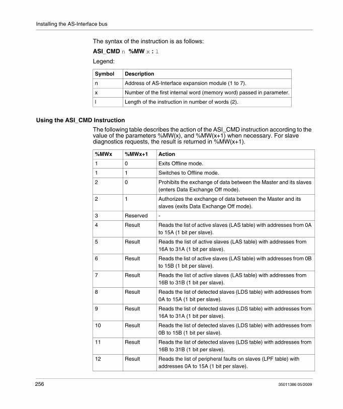
Installing the AS-Interface bus
The syntax of the instruction is as follows:
ASI_CMD n %MW x : l
Legend:
Using the ASI_CMD Instruction
The following table describes the action of the ASI_CMD instruction according to the value of the parameters %MW(x), and %MW(x+1) when necessary. For slave diagnostics requests, the result is returned in %MW(x+1).
Symbol Description
n Address of AS-Interface expansion module (1 to 7).
x Number of the first internal word (memory word) passed in parameter.
l Length of the instruction in number of words (2).
%MWx %MWx+1 Action
1 0 Exits Offline mode.
1 1 Switches to Offline mode.
2 0 Prohibits the exchange of data between the Master and its slaves (enters Data Exchange Off mode).
2 1 Authorizes the exchange of data between the Master and its slaves (exits Data Exchange Off mode).
3 Reserved -
4 Result Reads the list of active slaves (LAS table) with addresses from 0A to 15A (1 bit per slave).
5 Result Reads the list of active slaves (LAS table) with addresses from 16A to 31A (1 bit per slave).
6 Result Reads the list of active slaves (LAS table) with addresses from 0B to 15B (1 bit per slave).
7 Result Reads the list of active slaves (LAS table) with addresses from 16B to 31B (1 bit per slave).
8 Result Reads the list of detected slaves (LDS table) with addresses from 0A to 15A (1 bit per slave).
9 Result Reads the list of detected slaves (LDS table) with addresses from 16A to 31A (1 bit per slave).
10 Result Reads the list of detected slaves (LDS table) with addresses from 0B to 15B (1 bit per slave).
11 Result Reads the list of detected slaves (LDS table) with addresses from 16B to 31B (1 bit per slave).
12 Result Reads the list of peripheral faults on slaves (LPF table) with addresses 0A to 15A (1 bit per slave).
256 35011386 05/2009
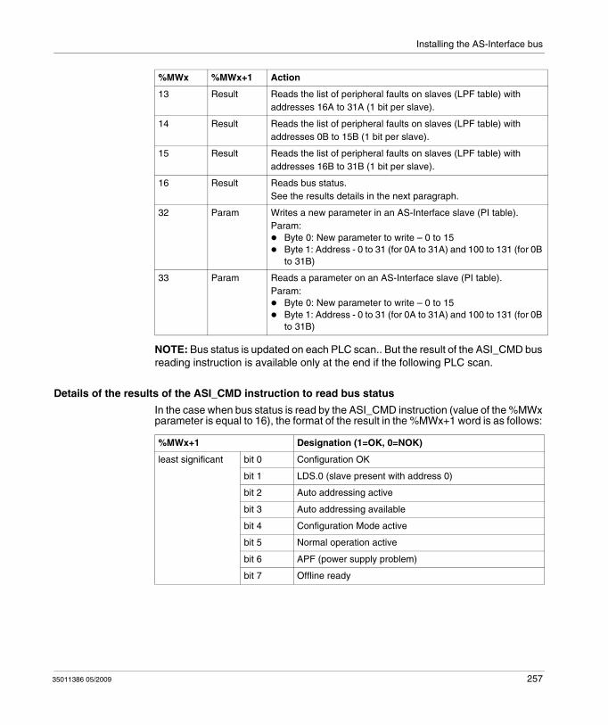
Installing the AS-Interface bus
NOTE: Bus status is updated on each PLC scan.. But the result of the ASI_CMD bus reading instruction is available only at the end if the following PLC scan.
Details of the results of the ASI_CMD instruction to read bus status
In the case when bus status is read by the ASI_CMD instruction (value of the %MWx parameter is equal to 16), the format of the result in the %MWx+1 word is as follows:
13 Result Reads the list of peripheral faults on slaves (LPF table) with addresses 16A to 31A (1 bit per slave).
14 Result Reads the list of peripheral faults on slaves (LPF table) with addresses 0B to 15B (1 bit per slave).
15 Result Reads the list of peripheral faults on slaves (LPF table) with addresses 16B to 31B (1 bit per slave).
16 Result Reads bus status.See the results details in the next paragraph.
32 Param Writes a new parameter in an AS-Interface slave (PI table).Param:
Byte 0: New parameter to write – 0 to 15Byte 1: Address - 0 to 31 (for 0A to 31A) and 100 to 131 (for 0B to 31B)
33 Param Reads a parameter on an AS-Interface slave (PI table).Param:
Byte 0: New parameter to write – 0 to 15Byte 1: Address - 0 to 31 (for 0A to 31A) and 100 to 131 (for 0B to 31B)
%MWx %MWx+1 Action
%MWx+1 Designation (1=OK, 0=NOK)
least significant bit 0 Configuration OK
bit 1 LDS.0 (slave present with address 0)
bit 2 Auto addressing active
bit 3 Auto addressing available
bit 4 Configuration Mode active
bit 5 Normal operation active
bit 6 APF (power supply problem)
bit 7 Offline ready
35011386 05/2009 257
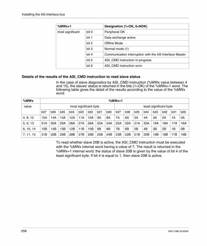
Installing the AS-Interface bus
Details of the results of the ASI_CMD instruction to read slave status
In the case of slave diagnostics by ASI_CMD instruction (%MWx value between 4 and 15), the slaves' status is returned in the bits (1=OK) of the %MWx+1 word. The following table gives the detail of the results according to the value of the %MWx word:
To read whether slave 20B is active, the ASI_CMD instruction must be executed with the %MWx internal word having a value of 7. The result is returned in the %MWx+1 internal word; the status of slave 20B is given by the value of bit 4 of the least significant byte: If bit 4 is equal to 1, then slave 20B is active.
most significant bit 0 Peripheral OK
bit 1 Data exchange active
bit 2 Offline Mode
bit 3 Normal mode (1)
bit 4 Communication interruption with the AS-Interface Master
bit 5 ASI_CMD instruction in progress
bit 6 ASI_CMD instruction error
%MWx+1 Designation (1=OK, 0=NOK)
%MWx %MWx+1
value most significant byte least significant byte
bit7 bit6 bit5 bit4 bit3 bit2 bit1 bit0 bit7 bit6 bit5 bit4 bit3 bit2 bit1 bit0
4, 8, 12 15A 14A 13A 12A 11A 10A 9A 8A 7A 6A 5A 4A 3A 2A 1A 0A
5, 9, 13 31A 30A 29A 28A 27A 26A 25A 24A 23A 22A 21A 20A 19A 18A 17A 16A
6, 10, 14 15B 14B 13B 12B 11B 10B 9B 8B 7B 6B 5B 4B 3B 2B 1B 0B
7, 11, 15 31B 30B 29B 28B 27B 26B 25B 24B 23B 22B 21B 20B 19B 18B 17B 16B
258 35011386 05/2009
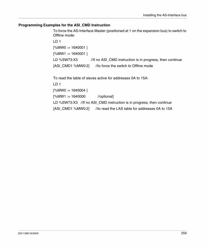
Installing the AS-Interface bus
Programming Examples for the ASI_CMD Instruction
To force the AS-Interface Master (positioned at 1 on the expansion bus) to switch to Offline mode:
LD 1
[%MW0 := 16#0001 ]
[%MW1 := 16#0001 ]
LD %SW73:X3 //If no ASI_CMD instruction is in progress, then continue
[ASI_CMD1 %MW0:2] //to force the switch to Offline mode
To read the table of slaves active for addresses 0A to 15A:
LD 1
[%MW0 := 16#0004 ]
[%MW1 := 16#0000 //optional]
LD %SW73:X3 //If no ASI_CMD instruction is in progress, then continue
[ASI_CMD1 %MW0:2] //to read the LAS table for addresses 0A to 15A
35011386 05/2009 259
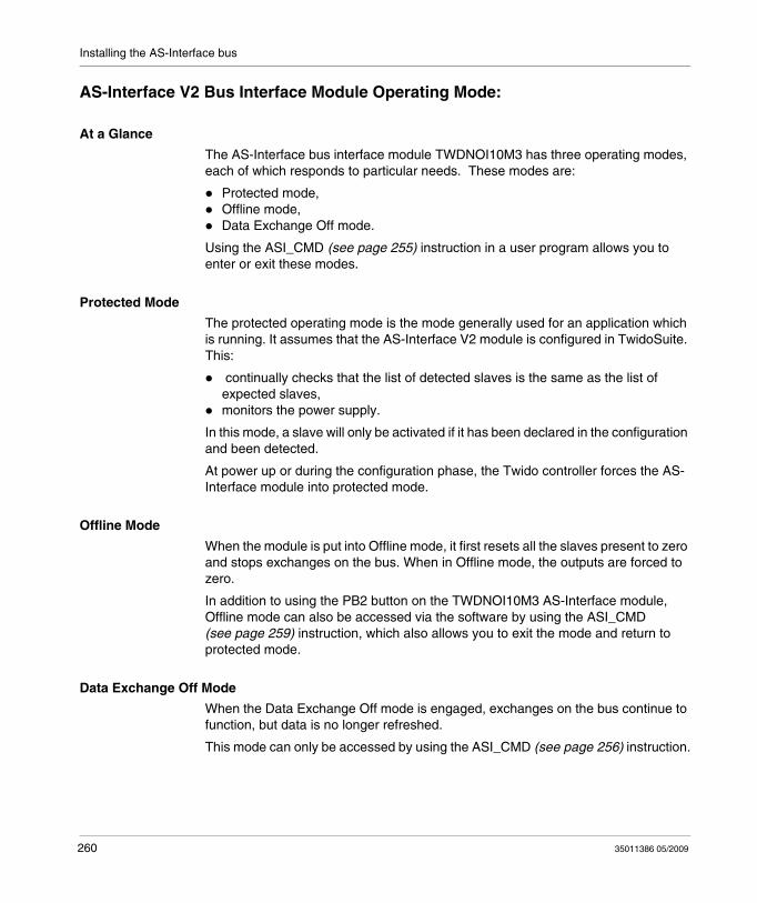
Installing the AS-Interface bus
AS-Interface V2 Bus Interface Module Operating Mode:
At a Glance
The AS-Interface bus interface module TWDNOI10M3 has three operating modes, each of which responds to particular needs. These modes are:
Protected mode,Offline mode,Data Exchange Off mode.
Using the ASI_CMD (see page 255) instruction in a user program allows you to enter or exit these modes.
Protected Mode
The protected operating mode is the mode generally used for an application which is running. It assumes that the AS-Interface V2 module is configured in TwidoSuite. This:
continually checks that the list of detected slaves is the same as the list of expected slaves,monitors the power supply.
In this mode, a slave will only be activated if it has been declared in the configuration and been detected.
At power up or during the configuration phase, the Twido controller forces the AS-Interface module into protected mode.
Offline Mode
When the module is put into Offline mode, it first resets all the slaves present to zero and stops exchanges on the bus. When in Offline mode, the outputs are forced to zero.
In addition to using the PB2 button on the TWDNOI10M3 AS-Interface module, Offline mode can also be accessed via the software by using the ASI_CMD (see page 259) instruction, which also allows you to exit the mode and return to protected mode.
Data Exchange Off Mode
When the Data Exchange Off mode is engaged, exchanges on the bus continue to function, but data is no longer refreshed.
This mode can only be accessed by using the ASI_CMD (see page 256) instruction.
260 35011386 05/2009

35011386 05/2009
10
Installing and Configuring the CANopen Fieldbus
35011386 05/2009
Installing and Configuring the CANopen Fieldbus
Subject of this Chapter
This chapter describes how to install and configure the TWDNCO1M CANopen master module, the Twido Extreme integrated CANopen bus and its slave devices on the CANopen fieldbus.
What's in this Chapter?
This chapter contains the following sections:
Section Topic Page
10.1 CANopen Fieldbus Overview 262
10.2 Implementing the CANopen Bus 276
261

Installing and Configuring the CANopen Fieldbus
10.1 CANopen Fieldbus Overview
Subject of this Section
This section is intended to provide you with general knowledge about the CANopen fieldbus technology and to introduce CAN-specific terminology that will be used throughout the remainder of this chapter.
What's in this Section?
This section contains the following topics:
Topic Page
CANopen Knowledge Base 263
About CANopen 264
CANOpen Boot-Up 267
Process Data Object (PDO) Transmission 270
Access to Data by Explicit Exchanges (SDO) 272
"Node Guarding" and "Life Guarding" 273
Internal Bus Management 275
35011386 05/2009 262
Installing and Configuring the CANopen Fieldbus
CANopen Knowledge Base
Introduction
The following describes useful technical terms and acronyms for CANopen network communication.
EDS file
EDS (Electronic Data Sheet)
An EDS file describes the communication properties of a device on the CAN network (baudrates, transmission types, I/O features, ...). It is provided by the device manufacturer. It is used in the configuration tool to configure a node (like a driver in an operating system).
PDO
PDO (Process Data Object)
CANopen frame containing I/O data.
We distinguish between:Transmit-PDOs (TPDOs with data provided by a node) andReceive-PDOs (RPDOs with data to be consumed by a node).
The transmission direction is always seen from a node's point of view. A PDO (either TPDO or RPDO) does not necessarily contain the whole data image of a node. Normally, analog input data and discrete input data are divided into different TPDOs. The same is true for outputs.
SDO
SDO (Service Data Object)
CANopen frames containing parameters.
SDOs are typically used to read or write parameters while the application is running.
COB-ID
COB-ID (Communication Object Identifier)
Each CANopen frame starts with a COB-ID working as the Identifier in the CAN frame. During the configuration phase, each node receives the COB-ID(s) of the frame(s) for which it is the provider (or consumer).
35011386 05/2009 263
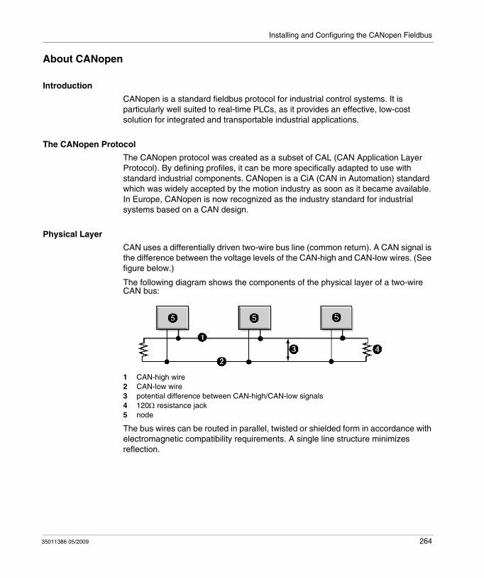
Installing and Configuring the CANopen Fieldbus
About CANopen
Introduction
CANopen is a standard fieldbus protocol for industrial control systems. It is particularly well suited to real-time PLCs, as it provides an effective, low-cost solution for integrated and transportable industrial applications.
The CANopen Protocol
The CANopen protocol was created as a subset of CAL (CAN Application Layer Protocol). By defining profiles, it can be more specifically adapted to use with standard industrial components. CANopen is a CiA (CAN in Automation) standard which was widely accepted by the motion industry as soon as it became available. In Europe, CANopen is now recognized as the industry standard for industrial systems based on a CAN design.
Physical Layer
CAN uses a differentially driven two-wire bus line (common return). A CAN signal is the difference between the voltage levels of the CAN-high and CAN-low wires. (See figure below.)
The following diagram shows the components of the physical layer of a two-wire CAN bus:
1 CAN-high wire2 CAN-low wire3 potential difference between CAN-high/CAN-low signals4 120Ω resistance jack 5 node
The bus wires can be routed in parallel, twisted or shielded form in accordance with electromagnetic compatibility requirements. A single line structure minimizes reflection.
35011386 05/2009 264
Installing and Configuring the CANopen Fieldbus
CANopen Profiles
The communication profile
The CANopen profile family is based on a "communication profile", which specifies the main communication mechanisms and their description (DS301).
The device profile
The most important types of devices used in industrial automation are described in the "Device profiles". They also define device functionalities.
Examples of the standard devices described are:
discrete and analog input/output modules (DS401),motors (DS402),control devices (DSP403),closed loop controllers (DSP404),PLCs (DS405),encoders (DS406).
Device Configuration via the CAN Bus
The ability to configure devices via the CAN bus is a basic requirement made by manufacturers (for each profile family) to ensure autonomy.
General Specifications for CANopen Profiles
CANopen is a set of profiles for CAN systems with the following specifications:
open bus system,real-time data exchange without protocol overload,modular design with possibility of resizing,interoperability and interchangeability of devices,supported by a large number of international manufacturers,standardized network configuration,access to all device parameters,synchronization and circulation of cyclical process data and/or event-driven data (possibility of short system response times).
CANopen Product Certification
All manufacturers offering CANopen-certified products on the market are members of the CiA group. As an active member of the CiA group, Schneider Electric Industries SAS develops its products in compliance with the standardization recommendations set by this association.
35011386 05/2009 265
Installing and Configuring the CANopen Fieldbus
CAN Standards
CANopen specifications are defined by the CiA group and can be accessed (subject to some restrictions) on the group site at http://www.can-cia.com. The sourcecodes for master and slave devices are available from the various suppliers.
NOTE: To find out more about CANopen standard specifications and mechanisms, please visit CiA's home page (http://www.can-cia.de/).
Communication on a CANopen Network
The communication profile is based on CAL services and protocols.
It provides the user with access to two types of exchange: SDO and PDO.
On power up, the device enters an initialization phase then goes into the Pre-operational state. At this stage, only SDO communication is authorized. After receiving a startup command, the device switches to the operational state. PDO exchanges can then be used, and SDO communication remains possible.
35011386 05/2009 266
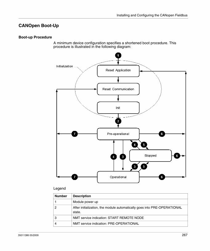
Installing and Configuring the CANopen Fieldbus
CANOpen Boot-Up
Boot-up Procedure
A minimum device configuration specifies a shortened boot procedure. This procedure is illustrated in the following diagram:
Legend
Number Description
1 Module power up
2 After initialization, the module automatically goes into PRE-OPERATIONAL state.
3 NMT service indication: START REMOTE NODE
4 NMT service indication: PRE-OPERATIONAL
35011386 05/2009 267
Installing and Configuring the CANopen Fieldbus
Active CANopen Objects depending on State Machine
The crosses in the table below indicate which CANopen objects are active in each state.
Reset Application
The device goes into the "Reset Application" state:
after the device starts up,or by using the "Reset Node" Network management (NMT) service.
In this state, the device profile is initialized, and all the device profile information is reset to default values. When initialization is complete, the device automatically goes into the "Reset Communication" state.
Reset Communication
The device goes into the "Reset Communication" state:
after the "Reset Application" state,or by using the "Reset Communication" Network management (NMT) service.
In this state, all the parameters (standard values, depending on the device configuration) of the supported communication objects (objects pertaining to device identification such as device type, heartbeat, etc.: 1000H - 1FFFH) are saved in the object directory. The device then automatically goes into the "Init" state.
5 NMT service indication: STOP REMOTE NODE
6 NMT service indication: RESET NODE
7 NMT service indication: RESET COMMUNICATION
Number Description
Initialization Pre-operational Operational Stopped
PDO object X
SDO object X X
Emergency X X
Boot-Up X X
NMT X X X
35011386 05/2009 268
Installing and Configuring the CANopen Fieldbus
Init
The device goes into "Init" mode after being in the "Reset Communication" state.
This state enables you to:
define the required communication objects (SDO, PDO, Emergency),install the corresponding CAL servicesconfigure the CAN-Controller.
Initialization of the device is complete and the device automatically goes into the "Pre-Operational" state.
NOTE: The TWDNCO1M CANopen master module and the Twido Extreme integrated CANopen bus master does not support SYNC mode.
Pre-Operational
The device goes into "Pre-Operational" state:
after the "Init" state, oron receiving the "Enter Pre-Operational" NMT indication if it was in Operational state.
When the device is in this state, its configuration can be modified. However, only SDOs can be used to read or write device-related data.
When configuration is complete, the device goes into one of the following states on receiving the corresponding indication:
"Stopped" on receiving the "STOP REMOTE NODE" NMT indication,"Operational" on receiving the "START REMOTE NODE" NMT indication.
Stopped
The device goes into the "Stopped" state on receiving the "Node stop" indication (NMT service) if it was in "Pre-Operational" or "Operational" state.
In this state, the device cannot be configured. No service is available to read and write device-related data (SDO). Only the slave monitoring function ("Node guarding") remains active.
Operational
The device goes into the "Operational" state if it was in the "Pre-Operational" state on receiving the "Start Remote Node" indication.
When the CANopen network is started using the "Node start" NMT services in "Operational" state, all device functionalities can be used. Communication can use PDOs or SDOs.
NOTE: Modifications to the configuration in "Operational" mode may have unexpected consequences and should therefore only be made in "Pre-Operational" mode.
35011386 05/2009 269
Installing and Configuring the CANopen Fieldbus
Process Data Object (PDO) Transmission
Definition of PDO
PDOs are objects which provide the communication interface with process data and enable them to be exchanged in real time. A CANOpen device's PDO set describes the implicit exchanges between this device and its communication partners on the network.
The exchange of PDOs is authorized when the device is in "Operational" mode.
Types of PDO
There are two types of PDO: PDOs transmitted by the device (often labeled:Transmit PDO or Tx-PDO or TPDO),PDOs received by the device (often labeled:Receive PDO or Rx-PDO or RPDO).
PDO Producers and Consumers
PDOs are based on a "Producer / Consumer" model. The device that sends out a PDO is called the "producer" whilst the one that receives it is known as the "consumer".
Thus, writing an output to the TWDNCO1M master module, or to the Twido Extreme integrated CANopen bus master, sends a TPDO associated with the master, which contains the value of the output to be updated. In this case, the master is the PDO "producer" (while the slave device is the PDO "consumer").
In contrast, an input is updated by the transmission of a RPDO by the master module which is then the "consumer".
PDO Transmission Mode
In addition to defining data to be transported, it is possible to configure the type of exchange for each PDO.
PDO can be exchanged by the TWDNCO1M master module, or by the Twido Extreme integrated CANopen bus master, in the following transmission mode:
Mode number Mode type Mode name
254 or 255 Asynchronous Change of state
35011386 05/2009 270
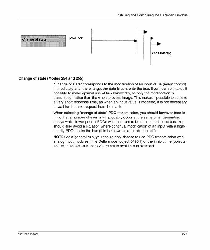
Installing and Configuring the CANopen Fieldbus
Change of state (Modes 254 and 255)
"Change of state" corresponds to the modification of an input value (event control). Immediately after the change, the data is sent onto the bus. Event control makes it possible to make optimal use of bus bandwidth, as only the modification is transmitted, rather than the whole process image. This makes it possible to achieve a very short response time, as when an input value is modified, it is not necessary to wait for the next request from the master.
When selecting "change of state" PDO transmission, you should however bear in mind that a number of events will probably occur at the same time, generating delays whilst lower priority PDOs wait their turn to be transmitted to the bus. You should also avoid a situation where continual modification of an input with a high-priority PDO blocks the bus (this is known as a "babbling idiot").
NOTE: As a general rule, you should only choose to use PDO transmission with analog input modules if the Delta mode (object 6426H) or the inhibit time (objects 1800H to 1804H, sub-index 3) are set to avoid a bus overload.
35011386 05/2009 271
Installing and Configuring the CANopen Fieldbus
Access to Data by Explicit Exchanges (SDO)
What is an SDO?
Service Data Objects (SDOs) allow a device's data to be accessed by using explicit requests.
The SDO service is available when the device is in an "Operational" or "Pre-Operational" state.
Types of SDO
There are two types of SDO:read SDOs (Download SDOs),write SDOs (Upload SDOs).
Client/Server Model
The SDO protocol is based on a 'Client / Server' model.
For a Download SDO
The client sends a request indicating the object to be read.
The server returns the data contained within the object.
For an Upload SDO
The client sends a request indicating the object to be written to and the desired value.
After the object has been updated, the server returns a confirmation message.
For an unprocessed SDO
In both cases, if an SDO could not be processed, the server returns an error code (abort code).
35011386 05/2009 272
Installing and Configuring the CANopen Fieldbus
"Node Guarding" and "Life Guarding"
Definition of Life-Time
The "Life time" parameter is calculated as follows:
Life Time = Guard Time x Life Time Factor
The object 100CH contains the ''Guard Time'' parameter expressed in milliseconds. The object 100DH contains the "Life Time Factor" parameter.
Activation of Monitoring
If one of these two parameters is set to "0" (default configuration) the module does not perform monitoring (no "Life Guarding").
To activate monitoring over time, you must at least enter the value 1 in the object 100DH and specify a time in ms in the object 100CH.
Improve Reliable Operation
To improve reliable operation, it is advisable to enter a "Life time factor" of 2.
If not, should a delay occur (for example due to processing of messages of the highest priority or internal processing on the "Node Guarding") master, the module switches into "Pre-Operational" state without generating an error notification.
Importance of Monitoring
These two monitoring mechanisms are particularly important to the CANopen system, given that devices do not usually operate in event-controlled mode.
Slave Monitoring
Monitoring is performed in the following way:
Phase Description
1 The master sets "Remote Frames" (remote transmit requests) on the "Guarding COB-IDs" of the slaves to be monitored.
2 The slaves concerned respond by sending the "Guarding" message. It contains the "Status Code" of the slave and the "Toggle Bit", which must change after each message.
3 The master compares the "Status" and "Toggle Bit" information:If they are not in the state expected by the NMT master or if no response is received, the master considers that an error is detected on the slave.
35011386 05/2009 273
Installing and Configuring the CANopen Fieldbus
Master Monitoring
If the master requests "Guarding" messages on a strictly cyclical basis, the slave can detect if a master is inoperative.
If the slave does not receive a request from the master within the defined "Life Time" interval (Guarding error), it considers that the master is inoperative ("Watchdog" function).
In this case, the corresponding outputs go into an error state and the slave switches back into "Pre-Operational" mode.
NOTE: The "Remote" request from the master obtains a response, even if there are no values entered in the "Guard Time" and "Life Time Factor" objects. Time monitoring is only activated when the values in the two objects are greater than 0. Typical values for the "Guard Time" parameter are between 250 ms and 2 seconds.
"Guarding" Protocol
The value of the ''Toggle Bit'' (t) sent in the first ''Guarding'' message is ''0''.
Then, the bit changes (''toggles'') in each subsequent ''Guarding'' message, which makes it possible to indicate if a message has been lost.
The bus head indicates its network state (s) in the seven remaining bits:
Network state Response
Stopped 0x04 or 0x84
Pre-operational 0x7F or 0xFF
Operational 0x05 or 0x85
35011386 05/2009 274
Installing and Configuring the CANopen Fieldbus
Internal Bus Management
Switching the Internal Bus to the "Stop" State
The internal bus automatically switches from the ''Stop'' to the ''Run'' state when the communication module switches from the "Pre-operational" to the "Operational" state.
When the internal bus switches to the "Stop" state all the expansion module* outputs are set to zero.
The communication module outputs are maintained in their current state.
Configuration of Expansion Modules
The internal bus is used to update the configuration of the discrete and analog expansion module* parameters.
The parameters are sent to the communication module when the bus is in the ''Stop'' state.
These new configuration parameters are acknowledged when the bus goes into the ''Run'' state.
NOTE: * Twido Extreme TWDLEDCK1 PLC does not support expansion modules.
35011386 05/2009 275
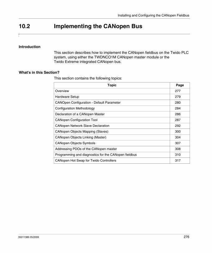
Installing and Configuring the CANopen Fieldbus
10.2 Implementing the CANopen Bus
Introduction
This section describes how to implement the CANopen fieldbus on the Twido PLC system, using either the TWDNCO1M CANopen master module or the Twido Extreme integrated CANopen bus.
What's in this Section?
This section contains the following topics:
Topic Page
Overview 277
Hardware Setup 279
CANOpen Configuration - Default Parameter 280
Configuration Methodology 284
Declaration of a CANopen Master 286
CANopen Configuration Tool 287
CANopen Network Slave Declaration 292
CANopen Objects Mapping (Slaves) 300
CANopen Objects Linking (Master) 304
CANopen Objects Symbols 307
Addressing PDOs of the CANopen master 308
Programming and diagnostics for the CANopen fieldbus 310
CANopen Hot Swap for Twido Controllers 317
35011386 05/2009 276
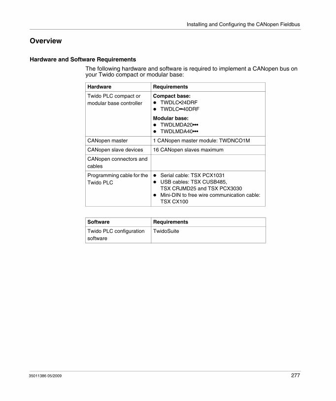
Installing and Configuring the CANopen Fieldbus
Overview
Hardware and Software Requirements
The following hardware and software is required to implement a CANopen bus on your Twido compact or modular base:
Hardware Requirements
Twido PLC compact or modular base controller
Compact base:TWDLC•24DRFTWDLC••40DRF
Modular base:TWDLMDA20•••TWDLMDA40•••
CANopen master 1 CANopen master module: TWDNCO1M
CANopen slave devices 16 CANopen slaves maximum
CANopen connectors and cables
Programming cable for the Twido PLC
Serial cable: TSX PCX1031USB cables: TSX CUSB485, TSX CRJMD25 and TSX PCX3030Mini-DIN to free wire communication cable: TSX CX100
Software Requirements
Twido PLC configuration software
TwidoSuite
35011386 05/2009 277
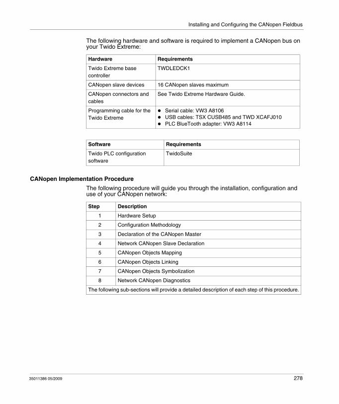
Installing and Configuring the CANopen Fieldbus
The following hardware and software is required to implement a CANopen bus on your Twido Extreme:
CANopen Implementation Procedure
The following procedure will guide you through the installation, configuration and use of your CANopen network:
Hardware Requirements
Twido Extreme base controller
TWDLEDCK1
CANopen slave devices 16 CANopen slaves maximum
CANopen connectors and cables
See Twido Extreme Hardware Guide.
Programming cable for the Twido Extreme
Serial cable: VW3 A8106USB cables: TSX CUSB485 and TWD XCAFJ010PLC BlueTooth adapter: VW3 A8114
Software Requirements
Twido PLC configuration software
TwidoSuite
Step Description
1 Hardware Setup
2 Configuration Methodology
3 Declaration of the CANopen Master
4 Network CANopen Slave Declaration
5 CANopen Objects Mapping
6 CANopen Objects Linking
7 CANopen Objects Symbolization
8 Network CANopen Diagnostics
The following sub-sections will provide a detailed description of each step of this procedure.
35011386 05/2009 278
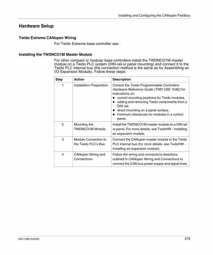
Installing and Configuring the CANopen Fieldbus
Hardware Setup
Twido Extreme CANopen Wiring
For Twido Extreme base controller see .
Installing the TWDNCO1M Master Module
For other compact or modular base controllers install the TWDNCO1M master module on a Twido PLC system (DIN-rail or panel mounting) and connect it to the Twido PLC internal bus (the connection method is the same as for Assembling an I/O Expansion Module). Follow these steps:
Step Action Description
1 Installation Preparation Consult the Twido Programmable Controllers Hardware Reference Guide (TWD USE 10AE) for instructions on:
correct mounting positions for Twido modules,adding and removing Twido components from a DIN rail,direct mounting on a panel surface,minimum clearances for modules in a control panel.
2 Mounting the TWDNCO1M Module
Install the TWDNCO1M master module on a DIN rail or panel. For more details, see TwdoHW - Installing an expansion module.
3 Module Connection to the Twido PLC’s Bus
Connect the CANopen master module to the Twido PLC internal bus (for more details, see TwdoHW - Installing an expansion module).
4 CANopen Wiring and Connections
Follow the wiring and connections directions outlined in CANopen Wiring and Connections to connect the CAN bus power supply and signal lines.
35011386 05/2009 279
Installing and Configuring the CANopen Fieldbus
CANOpen Configuration - Default Parameter
Overview
This functionality allows the user to configure the reset of CANOpen slaves.
User functionality
To reset the CANOpen slaves three configurations exist: Default Reset (Default Value):CANOpen Master choose which Reset is sent to slave (Reset Com only for Lexium 05, Reset All for all other slaves).Reset All Parameters:CANOpen Master forces the Reset All on the slave (even Lexium 05).Reset Communication Only (recommended for customers):CANOpen Master resets only communication of the slave.
Each configuration can be used for each slave.
35011386 05/2009 280
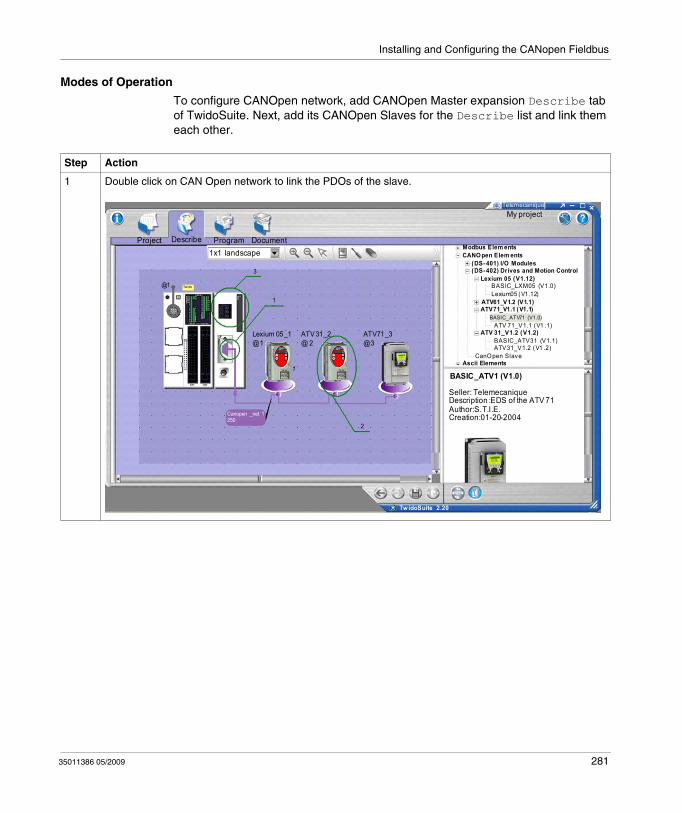
Installing and Configuring the CANopen Fieldbus
Modes of Operation
To configure CANOpen network, add CANOpen Master expansion Describe tab of TwidoSuite. Next, add its CANOpen Slaves for the Describe list and link them each other.
Step Action
1 Double click on CAN Open network to link the PDOs of the slave.
Project Describe Program Document
My projectTelemecanique
1x1 landscape
3
1
2
Lexium 05_1@1
ATV31_2@ 2
ATV71_3@3
Twido@1
1
Canopen _net 1250
Tw idoSuite 2.20
Modbus Elem entsCANO pen Elem ents
(DS-401) I/O Modules(DS-402) Drives and Motion Control
Lexium 05 (V1.12)BASIC_LXM05 (V1.0)Lexium05 (V1.12)
ATV61_V1.2 (V1.1)ATV71_V1.1 (V1.1)
BASIC_ ATV71 (V1.0)ATV 71_V1.1 (V1 .1)
ATV 31_V1.2 (V1.2)BASIC_ATV31 (V1.1)ATV31_V1.2 (V1 .2)
CanO pen SlaveAscii Elements
BASIC_ATV1 (V1.0)
Seller: TelemecaniqueDescription :EDS of the ATV 71Author:S.T.I.E.Creation:01-20-2004
35011386 05/2009 281
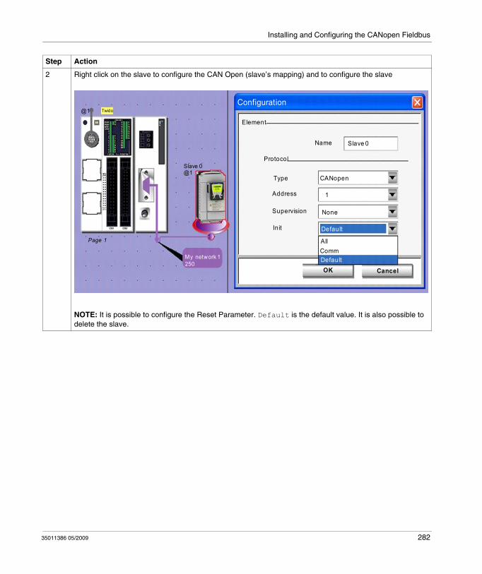
Installing and Configuring the CANopen Fieldbus
2 Right click on the slave to configure the CAN Open (slave’s mapping) and to configure the slave
NOTE: It is possible to configure the Reset Parameter. Default is the default value. It is also possible to delete the slave.
Step Action
@1 Twido
My network 1250
Slave 0@1
Page 1
Configuration
Element
Name Slave 0
Protocol
Type
Address
Supervision
Init
CANopen
1
None
Default
AllCommDefaultOK Cancel
35011386 05/2009 282
Installing and Configuring the CANopen Fieldbus
Compatibility
To implement this functionality, the compatibility level must be increased to 5.2.
NOTE: New applications generated with TwidoSuite V2.20 won’t be open with an oldest version of TwidoSuite. The Firmware is also impacted, a new version must be synchronized with TwidoSuite.
3 Double click on the CAN Open master to see the global configuration of the module on Configuration Part of TwidoSuite.
Step Action
35011386 05/2009 283
Installing and Configuring the CANopen Fieldbus
Configuration Methodology
Overview
The CANopen configuration is performed via the CANopen Configuration tools accessible from the Describe window in TwidoSuite.
NOTE:
1. CANopen network, master and slave configuration, as well as configuration of communication parameters is performed only in Offline mode.
2. No change to the CANopen configuration is allowed in Online mode.3. In Online mode, only certain parameters can be adjusted, such as %IWC and
%QWC PDO addressing parameters.
35011386 05/2009 284
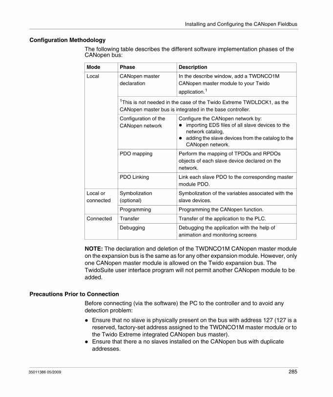
Installing and Configuring the CANopen Fieldbus
Configuration Methodology
The following table describes the different software implementation phases of the CANopen bus:
NOTE: The declaration and deletion of the TWDNCO1M CANopen master module on the expansion bus is the same as for any other expansion module. However, only one CANopen master module is allowed on the Twido expansion bus. The TwidoSuite user interface program will not permit another CANopen module to be added.
Precautions Prior to Connection
Before connecting (via the software) the PC to the controller and to avoid any detection problem:
Ensure that no slave is physically present on the bus with address 127 (127 is a reserved, factory-set address assigned to the TWDNCO1M master module or to the Twido Extreme integrated CANopen bus master).Ensure that there a no slaves installed on the CANopen bus with duplicate addresses.
Mode Phase Description
Local CANopen master declaration
In the describe window, add a TWDNCO1M CANopen master module to your Twido
application.1
1This is not needed in the case of the Twido Extreme TWDLDCK1, as the CANopen master bus is integrated in the base controller.
Configuration of the CANopen network
Configure the CANopen network by:importing EDS files of all slave devices to the network catalog,adding the slave devices from the catalog to the CANopen network.
PDO mapping Perform the mapping of TPDOs and RPDOs objects of each slave device declared on the network.
PDO Linking Link each slave PDO to the corresponding master module PDO.
Local or connected
Symbolization (optional)
Symbolization of the variables associated with the slave devices.
Programming Programming the CANopen function.
Connected Transfer Transfer of the application to the PLC.
Debugging Debugging the application with the help of animation and monitoring screens
35011386 05/2009 285
Installing and Configuring the CANopen Fieldbus
Declaration of a CANopen Master
Overview
This section explains how to declare a CANopen bus master module on your compact or modular controller internal bus.
NOTE: The information in the section is not applicable to Twido Extreme TWDLDCK1 base controller which has an integrated CANopen bus master module.
Procedure
The table below shows the different steps when declaring the master CANopen.
Step Action Comment
1 Select Describe step from the TwidoSuite interface.
See .
2 Display the product catalog and select a TWDNCO1M module to add to the system description.
See .Note: A TWDNCO1M master module can be inserted in any available expansion position. It can be subsequently moved to the left or right of other expansion modules.You may continue adding other expansions module (up to 7 including the TWDNCO1M module).Note: Only one TWDNCO1M CANopen master module is allowed.Only TWDC•A24DRF, TWDC••40DRF, TWDLMDA20••• and TWDLMDA40••• controllers are supported.
35011386 05/2009 286
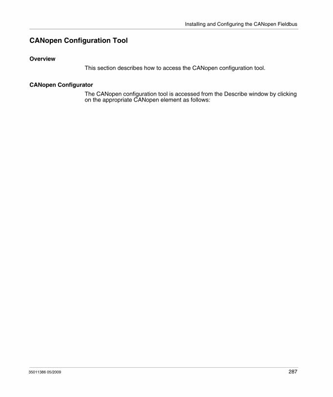
Installing and Configuring the CANopen Fieldbus
CANopen Configuration Tool
Overview
This section describes how to access the CANopen configuration tool.
CANopen Configurator
The CANopen configuration tool is accessed from the Describe window by clicking on the appropriate CANopen element as follows:
35011386 05/2009 287
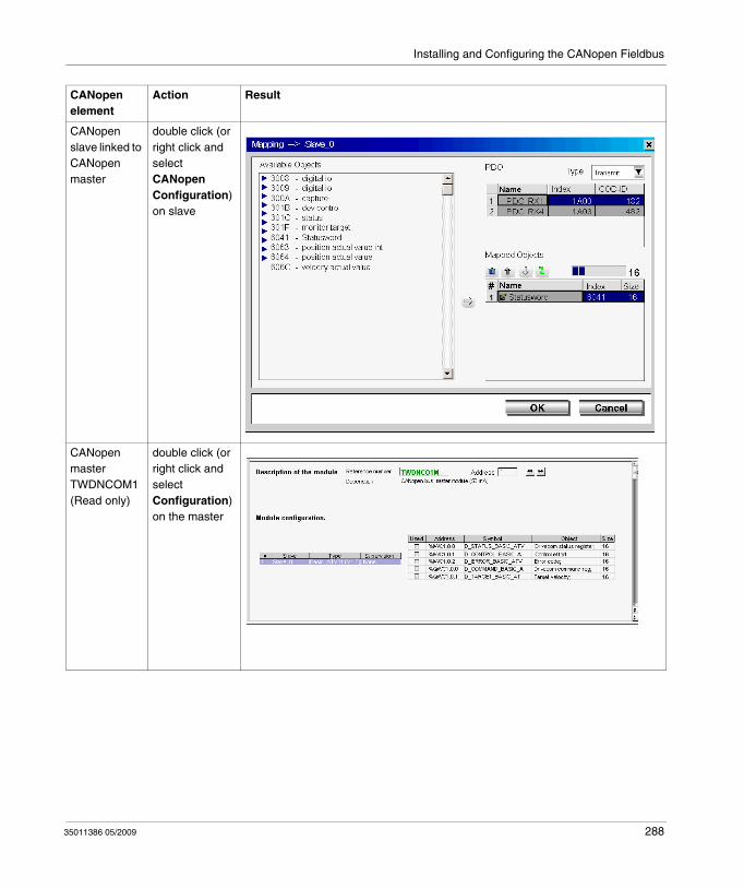
Installing and Configuring the CANopen Fieldbus
CANopen element
Action Result
CANopen slave linked to CANopen master
double click (or right click and select CANopen Configuration) on slave
CANopen master TWDNCOM1 (Read only)
double click (or right click and select Configuration) on the master
35011386 05/2009 288
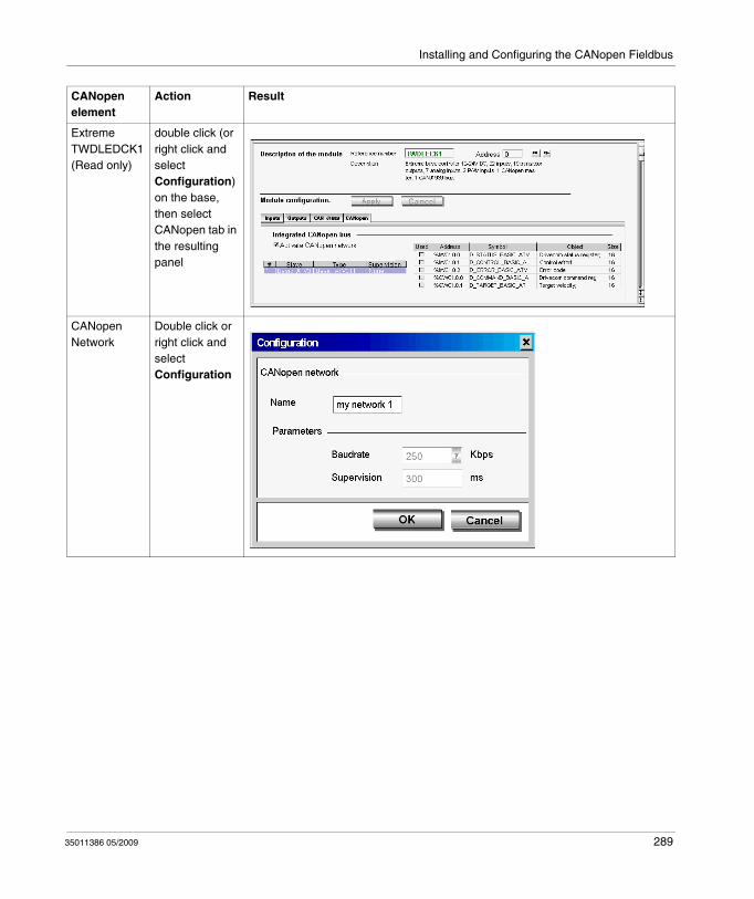
Installing and Configuring the CANopen Fieldbus
Extreme TWDLEDCK1 (Read only)
double click (or right click and select Configuration) on the base, then select CANopen tab in the resulting panel
CANopen Network
Double click or right click and select Configuration
CANopen element
Action Result
35011386 05/2009 289
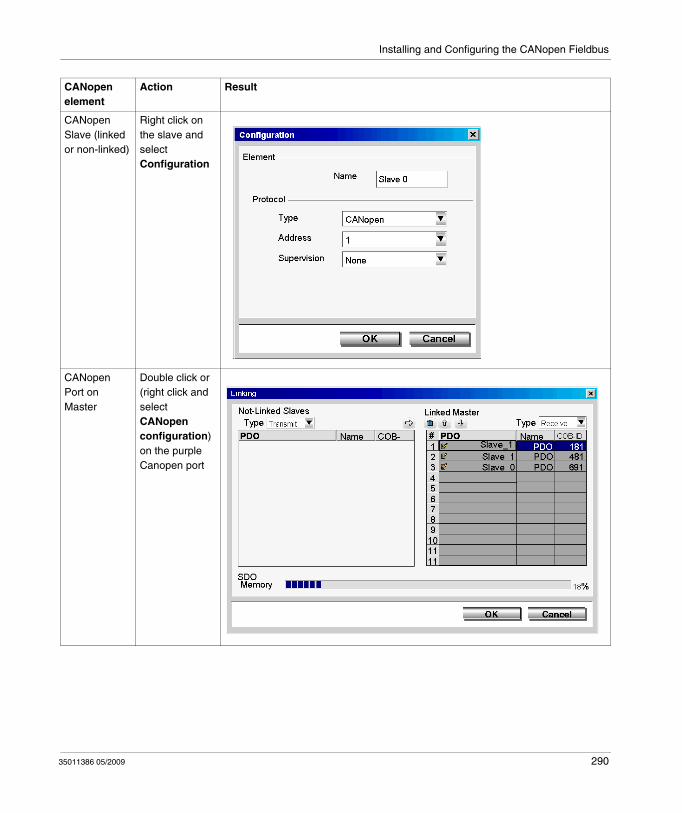
Installing and Configuring the CANopen Fieldbus
CANopen Slave (linked or non-linked)
Right click on the slave and select Configuration
CANopen Port on Master
Double click or (right click and select CANopen configuration) on the purple Canopen port
CANopen element
Action Result
35011386 05/2009 290

Installing and Configuring the CANopen Fieldbus
The Master CANopen configuration screen can also be viewed (but not edited) by selecting Program → Configure → Configure the Hardware task.
for Twido Extreme TWDLEDCK1, select the CANopen tab and click Configure.for other compact and modular base controllers, select the TWDNCO1M module in the upper graphical pane and click Configure in the lower configuration pane (there are no tabs for compact and modular PLCs).
NOTE: You can deactivate the Twido Extreme integrated CANopen bus master by clearing the Activate CANopen network check box in the CANopen tab of the configuration pane. This will free CANopen dedicated memory. Deactivating the Twido Extreme integrated CANopen bus master will delete the CANopen network configuration.
35011386 05/2009 291
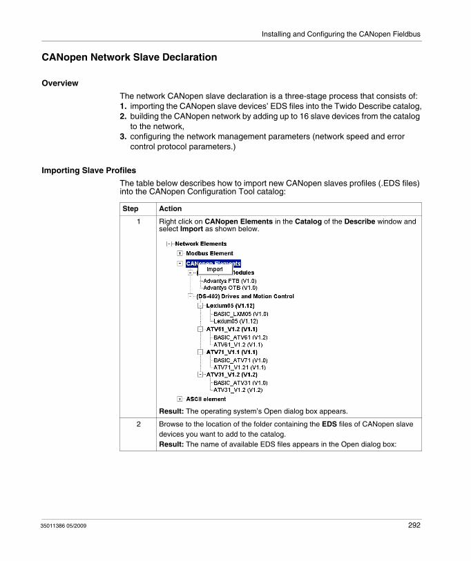
Installing and Configuring the CANopen Fieldbus
CANopen Network Slave Declaration
Overview
The network CANopen slave declaration is a three-stage process that consists of:1. importing the CANopen slave devices’ EDS files into the Twido Describe catalog,2. building the CANopen network by adding up to 16 slave devices from the catalog
to the network,3. configuring the network management parameters (network speed and error
control protocol parameters.)
Importing Slave Profiles
The table below describes how to import new CANopen slaves profiles (.EDS files) into the CANopen Configuration Tool catalog:
Step Action
1 Right click on CANopen Elements in the Catalog of the Describe window and select Import as shown below.
Result: The operating system’s Open dialog box appears.
2 Browse to the location of the folder containing the EDS files of CANopen slave devices you want to add to the catalog.Result: The name of available EDS files appears in the Open dialog box:
35011386 05/2009 292
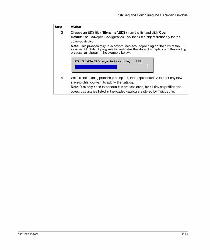
Installing and Configuring the CANopen Fieldbus
3 Choose an EDS file ("filename".EDS) from the list and click Open.Result: The CANopen Configuration Tool loads the object dictionary for the selected device. Note: This process may take several minutes, depending on the size of the selected EDS file. A progress bar indicates the state of completion of the loading process, as shown in the example below:
4 Wait till the loading process is complete, then repeat steps 2 to 3 for any new slave profile you want to add to the catalog.Note: You only need to perform this process once, for all device profiles and object dictionaries listed in the loaded catalog are stored by TwidoSuite.
Step Action
35011386 05/2009 293
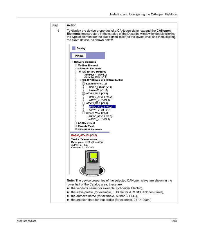
Installing and Configuring the CANopen Fieldbus
5 To display the device properties of a CANopen slave, expand the CANopen Elements tree structure in the catalog of the Describe window by double clicking the type of element (or the plus sign to its left)to the lowest level and then, clicking the slave device, as shown below:
Note: The device properties of the selected CANopen slave are shown in the lower half of the Catalog area, these are:
the vendor’s name (for example, Schneider Electric),the slave profile (for example, EDS file for ATV 31 CANopen Slave),the author’s name (for example, Author S.T.I.E.),the creation date for that profile (for example, 01-14-2004.)
Step Action
35011386 05/2009 294
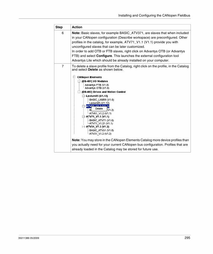
Installing and Configuring the CANopen Fieldbus
6 Note: Basic slaves, for example BASIC_ATV371, are slaves that when included in your CANopen configuration (Describe workspace) are preconfigured. Other profiles in the catalog, for example, ATV71_V1.1 (V1.1) provide you with unconfigured slaves that can be later customized.In order to add OTB or FTB slaves, right click on Advantys OTB (or Advantys FTB) and select Configure. This launches the external configuration tool Advantys Lite which should be already installed on your computer.
7 To delete a slave profile from the Catalog, right click on the profile, in the Catalog and select Delete as shown below.
Note: You may store in the CANopen Elements Catalog more device profiles than you actually need for your current CANopen bus configuration. Profiles that are already loaded in the Catalog may be stored for future use.
Step Action
35011386 05/2009 295
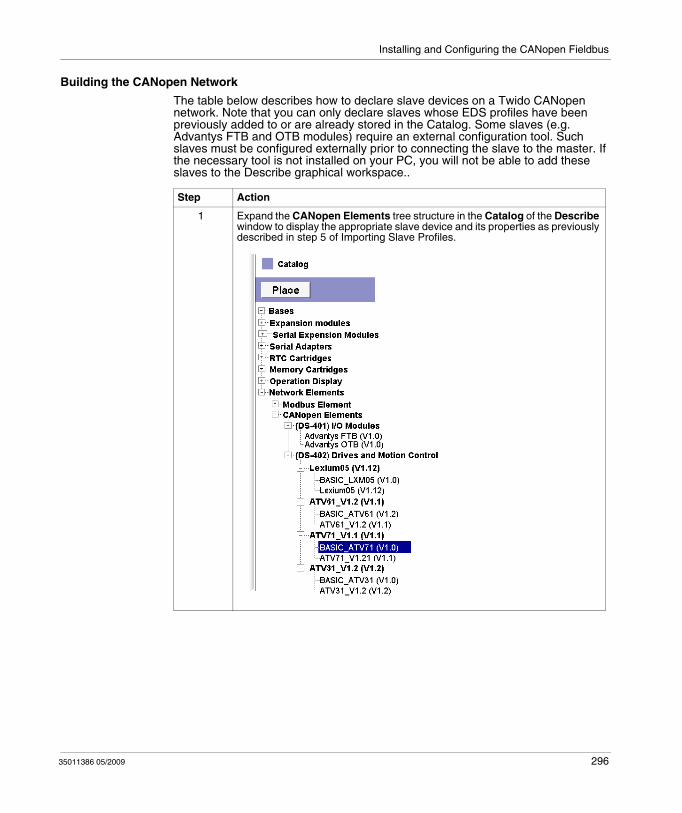
Installing and Configuring the CANopen Fieldbus
Building the CANopen Network
The table below describes how to declare slave devices on a Twido CANopen network. Note that you can only declare slaves whose EDS profiles have been previously added to or are already stored in the Catalog. Some slaves (e.g. Advantys FTB and OTB modules) require an external configuration tool. Such slaves must be configured externally prior to connecting the slave to the master. If the necessary tool is not installed on your PC, you will not be able to add these slaves to the Describe graphical workspace..
Step Action
1 Expand the CANopen Elements tree structure in the Catalog of the Describe window to display the appropriate slave device and its properties as previously described in step 5 of Importing Slave Profiles.
35011386 05/2009 296
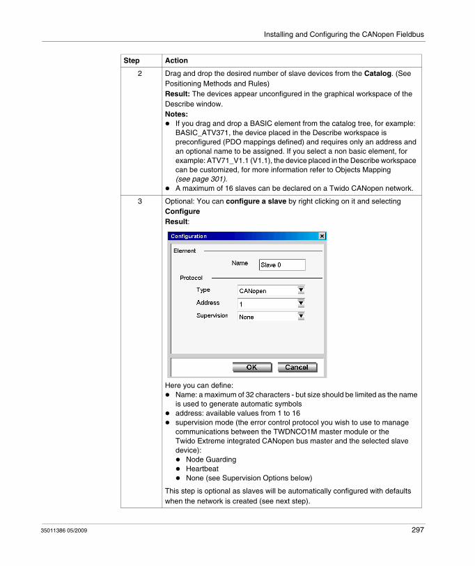
Installing and Configuring the CANopen Fieldbus
2 Drag and drop the desired number of slave devices from the Catalog. (See Positioning Methods and Rules)Result: The devices appear unconfigured in the graphical workspace of the Describe window.Notes:
If you drag and drop a BASIC element from the catalog tree, for example: BASIC_ATV371, the device placed in the Describe workspace is preconfigured (PDO mappings defined) and requires only an address and an optional name to be assigned. If you select a non basic element, for example: ATV71_V1.1 (V1.1), the device placed in the Describe workspace can be customized, for more information refer to Objects Mapping (see page 301).A maximum of 16 slaves can be declared on a Twido CANopen network.
3 Optional: You can configure a slave by right clicking on it and selecting ConfigureResult:
Here you can define:Name: a maximum of 32 characters - but size should be limited as the name is used to generate automatic symbolsaddress: available values from 1 to 16supervision mode (the error control protocol you wish to use to manage communications between the TWDNCO1M master module or the Twido Extreme integrated CANopen bus master and the selected slave device):
Node GuardingHeartbeatNone (see Supervision Options below)
This step is optional as slaves will be automatically configured with defaults when the network is created (see next step).
Step Action
35011386 05/2009 297
Installing and Configuring the CANopen Fieldbus
Supervision Options
The error control protocol you wish to use to manage communications between the TWDNCO1M master module or the Twido Extreme integrated CANopen bus master and the selected slave device is defined in the slave configuration with the following options:
Node GuardingHeartbeatNone
If the supervision option is set to None in the network slaves table, the outputs will not return to their fallback values in the event of a break in connection (*) between this slave and the TWDNCO1M master module or the Twido Extreme integrated CANopen bus master.
(*) this disconnection can be caused by:
disconnection of the expansion TWDNCO1M CANopen master module from the Twido PLC base controller (not applicable to Twido Extreme controller),disconnection of this CANopen slave from the Twido CANopen bus,
4 You can connect slaves to other slaves by Creating a Link. If the slaves are unconfigured they will remain unconfigured until they are connected to a CANopen master.
5 Connect the slaves to the CANopen master by Creating a Link.Result: The connected slave (if previously unconfigured) now displays a configuration with a name and node address. If the slave was previously configured it retains it configuration when it is connected to the master.The newly connected (previously unconfigured) slave device takes the node address with the lowest available index. (For example, if slave devices are declared at node addresses 1, 2 and 4, then a newly added slave device will take the available node address 3, as default.
6 You can change a slave’s name and assign it to any available node address (1 to 16) by configuring it as described in step 2.
7 Repeat steps 1 to 5 for any new slave device you want to declare on the CANopen network.
8 To delete a slave device or network link from the CANopen network, right click the object in the graphical workspace and select Delete.
9 To configure network management parameters, right click on the network link and select Configure (see Configuring the Network Management Parameters (see page 292)below).Note: The network management parameters can only be configured if the CANopen master is linked. If the CANopen master is not linked only the name of the network can be modified. (Default: my network x)
Step Action
35011386 05/2009 298
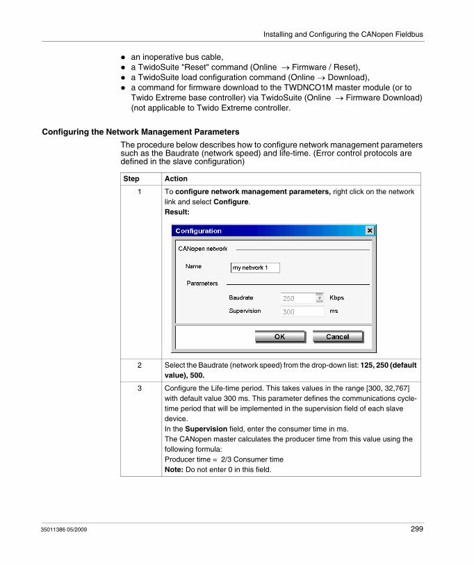
Installing and Configuring the CANopen Fieldbus
an inoperative bus cable,a TwidoSuite "Reset" command (Online → Firmware / Reset),a TwidoSuite load configuration command (Online → Download), a command for firmware download to the TWDNCO1M master module (or to Twido Extreme base controller) via TwidoSuite (Online → Firmware Download) (not applicable to Twido Extreme controller.
Configuring the Network Management Parameters
The procedure below describes how to configure network management parameters such as the Baudrate (network speed) and life-time. (Error control protocols are defined in the slave configuration)
Step Action
1 To configure network management parameters, right click on the network link and select Configure.Result:
2 Select the Baudrate (network speed) from the drop-down list: 125, 250 (default value), 500.
3 Configure the Life-time period. This takes values in the range [300, 32,767] with default value 300 ms. This parameter defines the communications cycle-time period that will be implemented in the supervision field of each slave device.In the Supervision field, enter the consumer time in ms. The CANopen master calculates the producer time from this value using the following formula:Producer time = 2/3 Consumer timeNote: Do not enter 0 in this field.
35011386 05/2009 299
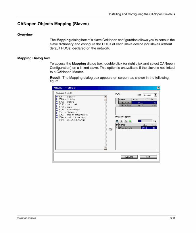
Installing and Configuring the CANopen Fieldbus
CANopen Objects Mapping (Slaves)
Overview
The Mapping dialog box of a slave CANopen configuration allows you to consult the slave dictionary and configure the PDOs of each slave device (for slaves without default PDOs) declared on the network.
Mapping Dialog box
To access the Mapping dialog box, double click (or right click and select CANopen Configuration) on a linked slave. This option is unavailable if the slave is not linked to a CANopen Master.
Result: The Mapping dialog box appears on screen, as shown in the following figure:
35011386 05/2009 300

Installing and Configuring the CANopen Fieldbus
Objects Mapping
To find out how to use the Mapping dialog box to configure the TPDOs and RPDOs of each slave device, follow these guidelines:
35011386 05/2009 301
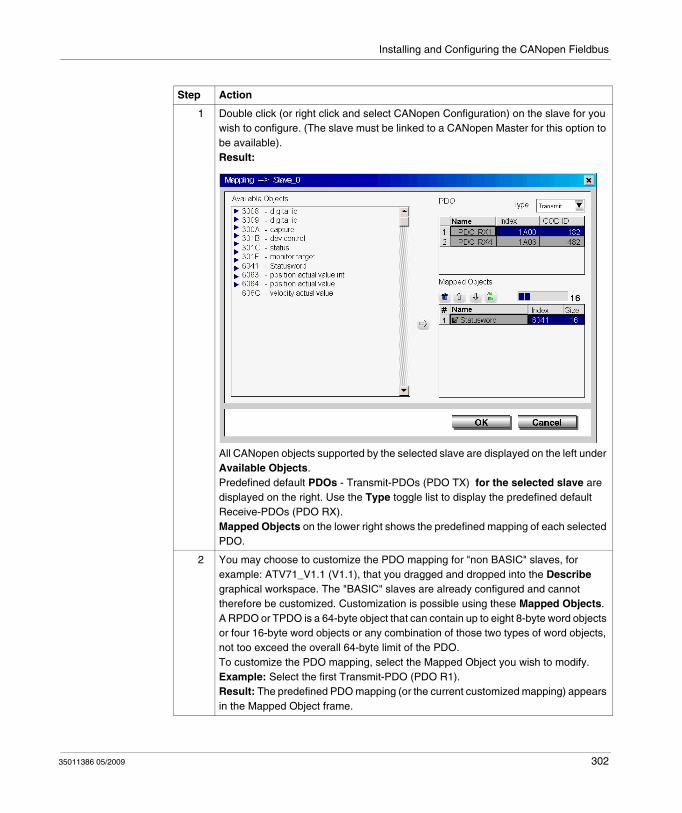
Installing and Configuring the CANopen Fieldbus
Step Action
1 Double click (or right click and select CANopen Configuration) on the slave for you wish to configure. (The slave must be linked to a CANopen Master for this option to be available).Result:
All CANopen objects supported by the selected slave are displayed on the left under Available Objects.Predefined default PDOs - Transmit-PDOs (PDO TX) for the selected slave are displayed on the right. Use the Type toggle list to display the predefined default Receive-PDOs (PDO RX). Mapped Objects on the lower right shows the predefined mapping of each selected PDO.
2 You may choose to customize the PDO mapping for "non BASIC" slaves, for example: ATV71_V1.1 (V1.1), that you dragged and dropped into the Describe graphical workspace. The "BASIC" slaves are already configured and cannot therefore be customized. Customization is possible using these Mapped Objects.A RPDO or TPDO is a 64-byte object that can contain up to eight 8-byte word objects or four 16-byte word objects or any combination of those two types of word objects, not too exceed the overall 64-byte limit of the PDO.To customize the PDO mapping, select the Mapped Object you wish to modify.Example: Select the first Transmit-PDO (PDO R1). Result: The predefined PDO mapping (or the current customized mapping) appears in the Mapped Object frame.
35011386 05/2009 302
Installing and Configuring the CANopen Fieldbus
3 To delete an unused word object from the PDO mapping structure, select the word
object (indexed 1 to 8) and click the Delete icon .
4 From the Available Objects frame, select the word object in the object family that
you wish to map, and click the Add icon to append the word object to the Mapped Objects structure.Note: To restore the default mapping structure for the selected PDO, click the
Default icon .
5 To change a word object’s address within the mapped PDO structure, use the Move
up/down arrow icons / .
6 Click OK to confirm changes to the mapped PDO structure and save the PDO mapping to the TwidoSuite project (or cancel to abandon modifications).
7 Repeat steps 2 through 6 for each PDO mapping you wish to configure.
8 PDO memory usage:Usage of PDO memory can be monitored via the memory status bar located on the
right in the Mapped Objects frame: .
Step Action
35011386 05/2009 303
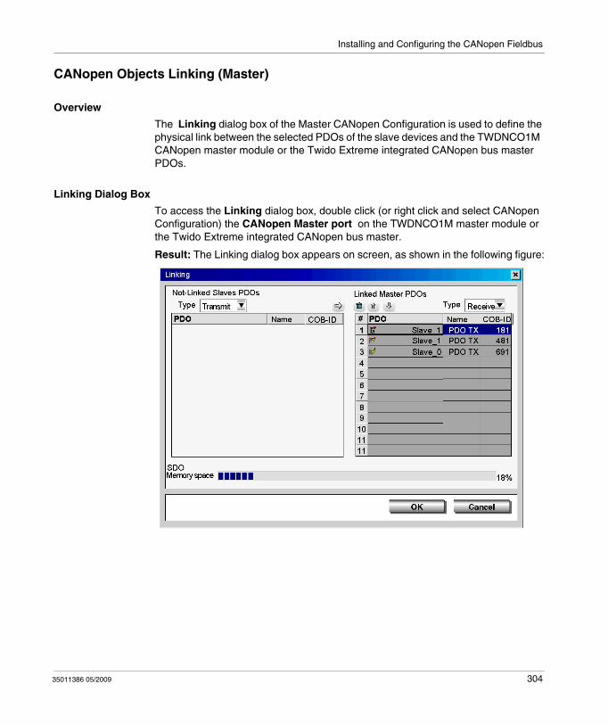
Installing and Configuring the CANopen Fieldbus
CANopen Objects Linking (Master)
Overview
The Linking dialog box of the Master CANopen Configuration is used to define the physical link between the selected PDOs of the slave devices and the TWDNCO1M CANopen master module or the Twido Extreme integrated CANopen bus master PDOs.
Linking Dialog Box
To access the Linking dialog box, double click (or right click and select CANopen Configuration) the CANopen Master port on the TWDNCO1M master module or the Twido Extreme integrated CANopen bus master.
Result: The Linking dialog box appears on screen, as shown in the following figure:
35011386 05/2009 304
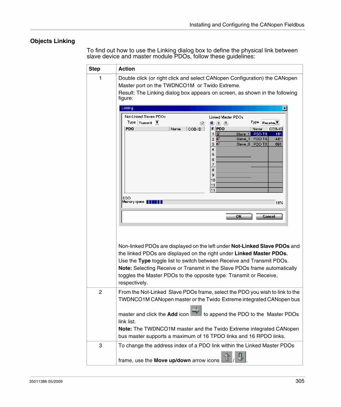
Installing and Configuring the CANopen Fieldbus
Objects Linking
To find out how to use the Linking dialog box to define the physical link between slave device and master module PDOs, follow these guidelines:
Step Action
1 Double click (or right click and select CANopen Configuration) the CANopen Master port on the TWDNCO1M or Twido Extreme.Result: The Linking dialog box appears on screen, as shown in the following figure:
Non-linked PDOs are displayed on the left under Not-Linked Slave PDOs and the linked PDOs are displayed on the right under Linked Master PDOs.Use the Type toggle list to switch between Receive and Transmit PDOs.Note: Selecting Receive or Transmit in the Slave PDOs frame automatically toggles the Master PDOs to the opposite type: Transmit or Receive, respectively.
2 From the Not-Linked Slave PDOs frame, select the PDO you wish to link to the TWDNCO1M CANopen master or the Twido Extreme integrated CANopen bus
master and click the Add icon to append the PDO to the Master PDOs link list.Note: The TWDNCO1M master and the Twido Extreme integrated CANopen bus master supports a maximum of 16 TPDO links and 16 RPDO links.
3 To change the address index of a PDO link within the Linked Master PDOs
frame, use the Move up/down arrow icons / .
35011386 05/2009 305
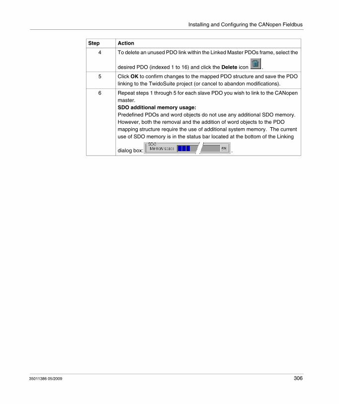
Installing and Configuring the CANopen Fieldbus
4 To delete an unused PDO link within the Linked Master PDOs frame, select the
desired PDO (indexed 1 to 16) and click the Delete icon .
5 Click OK to confirm changes to the mapped PDO structure and save the PDO linking to the TwidoSuite project (or cancel to abandon modifications).
6 Repeat steps 1 through 5 for each slave PDO you wish to link to the CANopen master.SDO additional memory usage:Predefined PDOs and word objects do not use any additional SDO memory. However, both the removal and the addition of word objects to the PDO mapping structure require the use of additional system memory. The current use of SDO memory is in the status bar located at the bottom of the Linking
dialog box: .
Step Action
35011386 05/2009 306
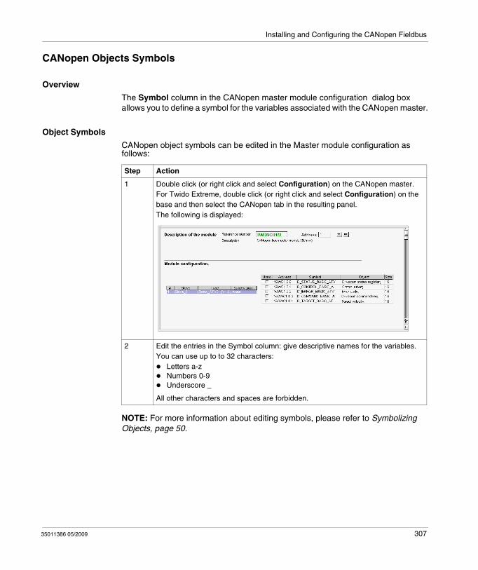
Installing and Configuring the CANopen Fieldbus
CANopen Objects Symbols
Overview
The Symbol column in the CANopen master module configuration dialog box allows you to define a symbol for the variables associated with the CANopen master.
Object Symbols
CANopen object symbols can be edited in the Master module configuration as follows:
NOTE: For more information about editing symbols, please refer to Symbolizing Objects, page 50.
Step Action
1 Double click (or right click and select Configuration) on the CANopen master.For Twido Extreme, double click (or right click and select Configuration) on the base and then select the CANopen tab in the resulting panel.The following is displayed:
2 Edit the entries in the Symbol column: give descriptive names for the variables.You can use up to to 32 characters:
Letters a-zNumbers 0-9Underscore _
All other characters and spaces are forbidden.
35011386 05/2009 307
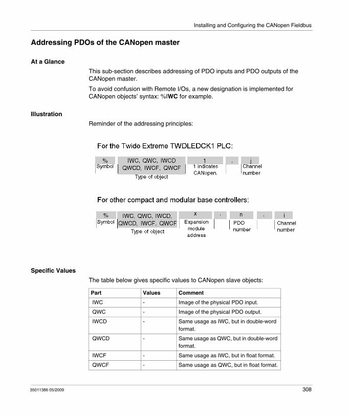
Installing and Configuring the CANopen Fieldbus
Addressing PDOs of the CANopen master
At a Glance
This sub-section describes addressing of PDO inputs and PDO outputs of the CANopen master.
To avoid confusion with Remote I/Os, a new designation is implemented for CANopen objects’ syntax: %IWC for example.
Illustration
Reminder of the addressing principles:
Specific Values
The table below gives specific values to CANopen slave objects:
Part Values Comment
IWC - Image of the physical PDO input.
QWC - Image of the physical PDO output.
IWCD - Same usage as IWC, but in double-word format.
QWCD - Same usage as QWC, but in double-word format.
IWCF - Same usage as IWC, but in float format.
QWCF - Same usage as QWC, but in float format.
35011386 05/2009 308
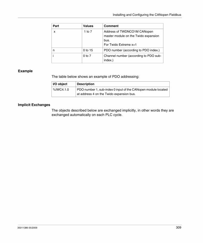
Installing and Configuring the CANopen Fieldbus
Example
The table below shows an example of PDO addressing:
Implicit Exchanges
The objects described below are exchanged implicitly, in other words they are exchanged automatically on each PLC cycle.
x 1 to 7 Address of TWDNCO1M CANopen master module on the Twido expansion bus.For Twido Extreme x=1
n 0 to 15 PDO number (according to PDO index.)
i 0 to 7 Channel number (according to PDO sub-index.)
Part Values Comment
I/O object Description
%IWC4.1.0 PDO number 1, sub-index 0 input of the CANopen module located at address 4 on the Twido expansion bus.
35011386 05/2009 309

Installing and Configuring the CANopen Fieldbus
Programming and diagnostics for the CANopen fieldbus
Explicit Exchanges
Objects (words and bits) associated with the CANopen fieldbus contribute data (for example: bus operation, slave status, etc.) and additional commands to carry out advanced programming of the CANopen function.
These objects are exchanged explicitly between the Twido controller and the CANopen Master module via the expansion bus:
at the request of the program user by way of the instruction: CAN_CMD (see "Presentation of the CAN_CMD" instruction below)via the debug screen or the animation table.
CANopen Master Reserved Specific System Words
System words reserved in the Twido controller for the TWDNCO1M CANopen Master module enable you to determine the status of the network: %SW8x (x=1-7) is reserved for the CANopen master moduled installed at expansion address x on the Twido bus. Only the first 7 bits of these words are used; they are read-only.
For the Twido Extreme integrated CANopen bus master the reserved specific system word is always %SW81 (%SW82... %SW87 are unused).
The following table shows the bits used:
System Words
Bit Description
%SW8x(x=1-7)
0 Configuration status of CANopen master ( = 1 if configuration OK, otherwise 0)
1 Operational mode of CANopen master ( = 1 data exchange is enabled, otherwise 0)
2 System stopped ( = 1 if the Offline mode is enabled, otherwise 0)
3 CAN_CMD instruction complete ( = 1 if command complete, otherwise 0 when command is in progress)
4 CAN_CMD instruction error ( = 1 if there is an error in the instruction, otherwise 0)
5 Initialization error ( = 1)
6 Loss of message, "power supply related error ( = 1)"
35011386 05/2009 310
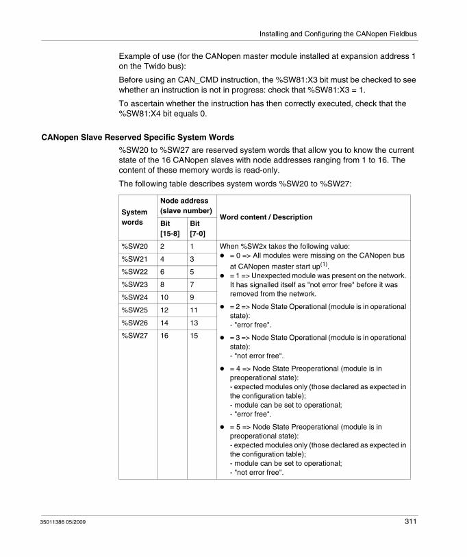
Installing and Configuring the CANopen Fieldbus
Example of use (for the CANopen master module installed at expansion address 1 on the Twido bus):
Before using an CAN_CMD instruction, the %SW81:X3 bit must be checked to see whether an instruction is not in progress: check that %SW81:X3 = 1.
To ascertain whether the instruction has then correctly executed, check that the %SW81:X4 bit equals 0.
CANopen Slave Reserved Specific System Words
%SW20 to %SW27 are reserved system words that allow you to know the current state of the 16 CANopen slaves with node addresses ranging from 1 to 16. The content of these memory words is read-only.
The following table describes system words %SW20 to %SW27:
System words
Node address (slave number)
Word content / DescriptionBit[15-8]
Bit[7-0]
%SW20 2 1 When %SW2x takes the following value:= 0 => All modules were missing on the CANopen bus
at CANopen master start up(1).= 1 => Unexpected module was present on the network. It has signalled itself as "not error free" before it was removed from the network.
= 2 => Node State Operational (module is in operational state): - "error free".
= 3 => Node State Operational (module is in operational state): - "not error free".
= 4 => Node State Preoperational (module is in preoperational state): - expected modules only (those declared as expected in the configuration table);- module can be set to operational;- "error free".
= 5 => Node State Preoperational (module is in preoperational state): - expected modules only (those declared as expected in the configuration table);- module can be set to operational;- "not error free".
%SW21 4 3
%SW22 6 5
%SW23 8 7
%SW24 10 9
%SW25 12 11
%SW26 14 13
%SW27 16 15
35011386 05/2009 311
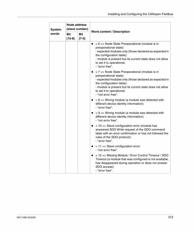
Installing and Configuring the CANopen Fieldbus
= 6 => Node State Preoperational (module is in preoperational state): - expected modules only (those declared as expected in the configuration table);- module is present but its current state does not allow to set it to operational;- "error free".
= 7 => Node State Preoperational (module is in preoperational state): - expected modules only (those declared as expected in the configuration table);- module is present but its current state does not allow to set it to operational;- "not error free".
= 8 => Wrong module (a module was detected with different device identity information): - "error free".
= 9 => Wrong module (a module was detected with different device identity information): - "not error free".
= 10 => Slave configuration error (module has answered SDO Write request of the SDO command table with an error confirmation or has not followed the rules of the SDO protocol): - "error free".
= 11 => Slave configuration error: - "not error free".
= 12 => Missing Module / Error Control Timeout / SDO Timeout (a module that was configured is not available, has disappeared during operation or does not answer SDO access): - "error free".
System words
Node address (slave number)
Word content / DescriptionBit[15-8]
Bit[7-0]
35011386 05/2009 312
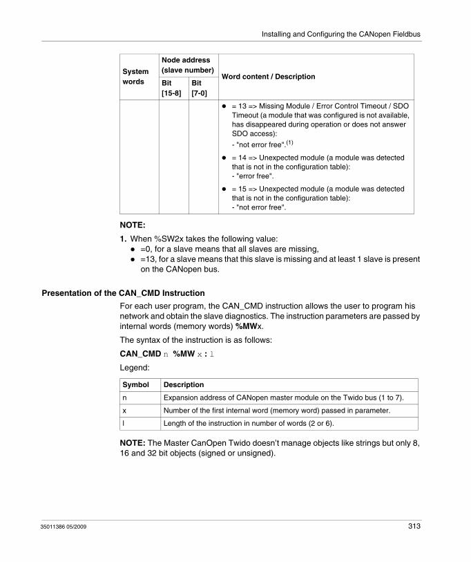
Installing and Configuring the CANopen Fieldbus
NOTE:
1. When %SW2x takes the following value:=0, for a slave means that all slaves are missing,=13, for a slave means that this slave is missing and at least 1 slave is present on the CANopen bus.
Presentation of the CAN_CMD Instruction
For each user program, the CAN_CMD instruction allows the user to program his network and obtain the slave diagnostics. The instruction parameters are passed by internal words (memory words) %MWx.
The syntax of the instruction is as follows:
CAN_CMD n %MW x : l
Legend:
NOTE: The Master CanOpen Twido doesn’t manage objects like strings but only 8, 16 and 32 bit objects (signed or unsigned).
= 13 => Missing Module / Error Control Timeout / SDO Timeout (a module that was configured is not available, has disappeared during operation or does not answer SDO access):
- "not error free".(1)
= 14 => Unexpected module (a module was detected that is not in the configuration table): - "error free".
= 15 => Unexpected module (a module was detected that is not in the configuration table): - "not error free".
System words
Node address (slave number)
Word content / DescriptionBit[15-8]
Bit[7-0]
Symbol Description
n Expansion address of CANopen master module on the Twido bus (1 to 7).
x Number of the first internal word (memory word) passed in parameter.
l Length of the instruction in number of words (2 or 6).
35011386 05/2009 313
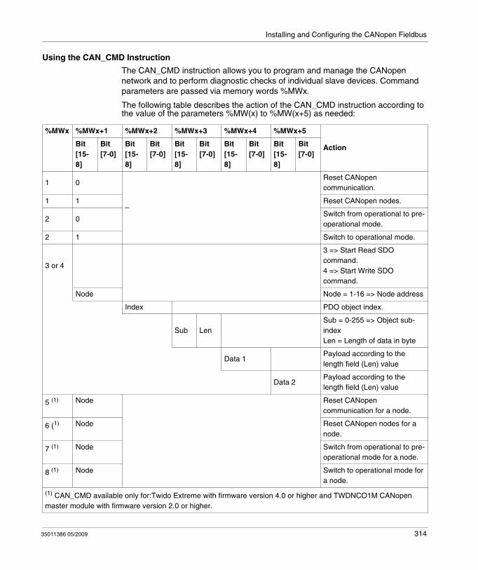
Installing and Configuring the CANopen Fieldbus
Using the CAN_CMD Instruction
The CAN_CMD instruction allows you to program and manage the CANopen network and to perform diagnostic checks of individual slave devices. Command parameters are passed via memory words %MWx.
The following table describes the action of the CAN_CMD instruction according to the value of the parameters %MW(x) to %MW(x+5) as needed:
%MWx %MWx+1 %MWx+2 %MWx+3 %MWx+4 %MWx+5
ActionBit[15-8]
Bit[7-0]
Bit[15-8]
Bit[7-0]
Bit[15-8]
Bit[7-0]
Bit[15-8]
Bit[7-0]
Bit[15-8]
Bit[7-0]
1 0
–
Reset CANopen communication.
1 1 Reset CANopen nodes.
2 0Switch from operational to pre-operational mode.
2 1 Switch to operational mode.
3 or 4
3 => Start Read SDO command.4 => Start Write SDO command.
Node Node = 1-16 => Node address
Index PDO object index.
Sub LenSub = 0-255 => Object sub-indexLen = Length of data in byte
Data 1Payload according to the length field (Len) value
Data 2Payload according to the length field (Len) value
5 (1) Node Reset CANopen communication for a node.
6 (1) Node Reset CANopen nodes for a node.
7 (1) Node Switch from operational to pre-operational mode for a node.
8 (1) Node Switch to operational mode for a node.
(1) CAN_CMD available only for:Twido Extreme with firmware version 4.0 or higher and TWDNCO1M CANopen master module with firmware version 2.0 or higher.
35011386 05/2009 314
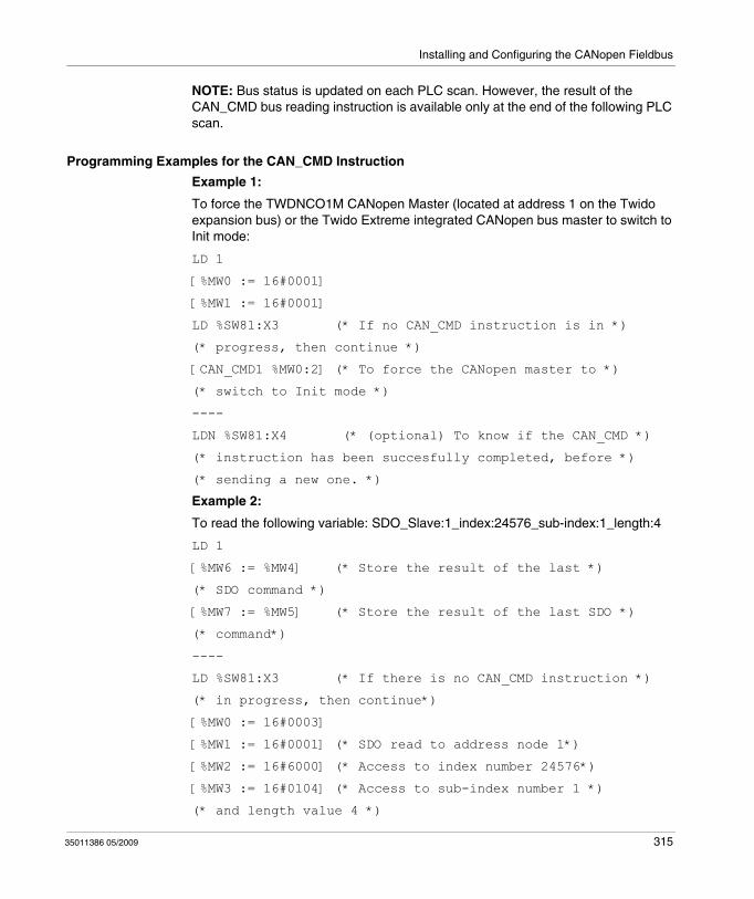
Installing and Configuring the CANopen Fieldbus
NOTE: Bus status is updated on each PLC scan. However, the result of the CAN_CMD bus reading instruction is available only at the end of the following PLC scan.
Programming Examples for the CAN_CMD Instruction
Example 1:
To force the TWDNCO1M CANopen Master (located at address 1 on the Twido expansion bus) or the Twido Extreme integrated CANopen bus master to switch to Init mode:
LD 1
[%MW0 := 16#0001]
[%MW1 := 16#0001]
LD %SW81:X3 (* If no CAN_CMD instruction is in *)
(* progress, then continue *)
[CAN_CMD1 %MW0:2] (* To force the CANopen master to *)
(* switch to Init mode *)
----
LDN %SW81:X4 (* (optional) To know if the CAN_CMD *)
(* instruction has been succesfully completed, before *)
(* sending a new one. *)
Example 2:
To read the following variable: SDO_Slave:1_index:24576_sub-index:1_length:4
LD 1
[%MW6 := %MW4] (* Store the result of the last *)
(* SDO command *)
[%MW7 := %MW5] (* Store the result of the last SDO *)
(* command*)
----
LD %SW81:X3 (* If there is no CAN_CMD instruction *)
(* in progress, then continue*)
[%MW0 := 16#0003]
[%MW1 := 16#0001] (* SDO read to address node 1*)
[%MW2 := 16#6000] (* Access to index number 24576*)
[%MW3 := 16#0104] (* Access to sub-index number 1 *)
(* and length value 4 *)
35011386 05/2009 315
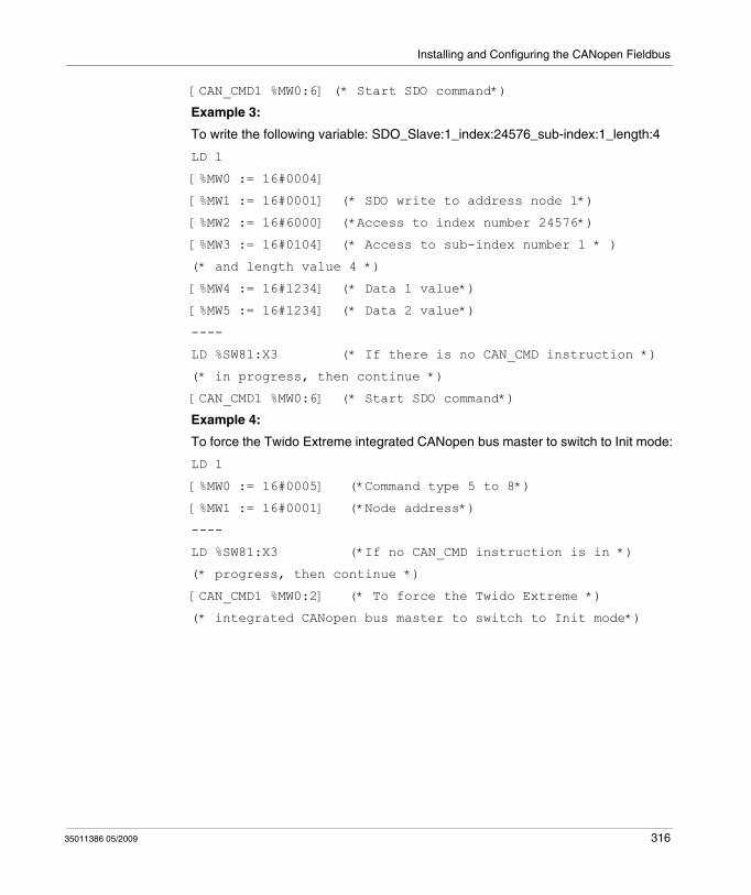
Installing and Configuring the CANopen Fieldbus
[CAN_CMD1 %MW0:6] (* Start SDO command*)
Example 3:
To write the following variable: SDO_Slave:1_index:24576_sub-index:1_length:4
LD 1
[%MW0 := 16#0004]
[%MW1 := 16#0001] (* SDO write to address node 1*)
[%MW2 := 16#6000] (*Access to index number 24576*)
[%MW3 := 16#0104] (* Access to sub-index number 1 * )
(* and length value 4 *)
[%MW4 := 16#1234] (* Data 1 value*)
[%MW5 := 16#1234] (* Data 2 value*)
----
LD %SW81:X3 (* If there is no CAN_CMD instruction *)
(* in progress, then continue *)
[CAN_CMD1 %MW0:6] (* Start SDO command*)
Example 4:
To force the Twido Extreme integrated CANopen bus master to switch to Init mode:
LD 1
[%MW0 := 16#0005] (*Command type 5 to 8*)
[%MW1 := 16#0001] (*Node address*)
----
LD %SW81:X3 (*If no CAN_CMD instruction is in *)
(* progress, then continue *)
[CAN_CMD1 %MW0:2] (* To force the Twido Extreme *)
(* integrated CANopen bus master to switch to Init mode*)
35011386 05/2009 316

Installing and Configuring the CANopen Fieldbus
CANopen Hot Swap for Twido Controllers
CANopen Hot Swap
The CANopen network with a Twido Controller and CANopen master TWDNCO1M (with firmware version 2.0 or higher) supports hot swap. The Twido Extreme also supports hot swap. Hot swap means that you can disconnect and reconnect a CANopen slave without switching off/on the master (or without disconnecting it from the PLC in the case of a Twido Extreme controller).
Hot Swap Compatibility
The hot swap functionality is available only if node supervision (Guard Time or HeartBeat) has been configured. For more details on how to configure node supervision see Configuring the Network Management Parameters, page 299.
35011386 05/2009 317

35011386 05/2009
11
Installing and Configuring the CANJ1939 Fieldbus
35011386 05/2009
Installing and Configuring the CANJ1939 Fieldbus
Subject of this Chapter
This chapter describes how to install and configure a CANJ1939 Fieldbus with a Twido Extreme TWDLEDCK1 base controller.
What's in this Chapter?
This chapter contains the following sections:
Section Topic Page
11.1 CANJ1939 Fieldbus Overview 319
11.2 Implementing the CANJ1939 Bus 326
318
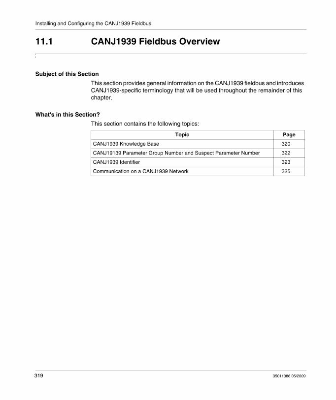
Installing and Configuring the CANJ1939 Fieldbus
11.1 CANJ1939 Fieldbus Overview
Subject of this Section
This section provides general information on the CANJ1939 fieldbus and introduces CANJ1939-specific terminology that will be used throughout the remainder of this chapter.
What's in this Section?
This section contains the following topics:
Topic Page
CANJ1939 Knowledge Base 320
CANJ19139 Parameter Group Number and Suspect Parameter Number 322
CANJ1939 Identifier 323
Communication on a CANJ1939 Network 325
319 35011386 05/2009
Installing and Configuring the CANJ1939 Fieldbus
CANJ1939 Knowledge Base
Introduction
The following section provides basic information about CANJ1939 network communications.
Applications
CANJ1939 is a high layer protocol for the CAN fieldbus developed by the SAE (Society of Automotive Engineers) for equipment used in industries ranging from agriculture, construction, and fire/rescue to forestry, materials handling, and on- and off-highway equipment.
Characteristics
CANJ1939 is a high speed communications network designed to support real-time closed loop control functions between electronic devices which may be physically distributed throughout the vehicle.
CANJ1939 is capable of performing all of the functions of J1708/J1587 as well as the control system support and any one application may utilize one or the other or both of these networks.
NOTE: Jl708/Jl587 is an older, widely used, network intended to provide simple information exchange, including diagnostic data, between electronic devices.
Electronic Control Unit (ECU)
Electronic Control Unit (ECU) is a computer based electronic assembly from which CANJ1939 messages may be sent or received.
In the remainder of this document ECUs are called CANJ1939 elements.
Parameter Group Number (PGN)
In the CANJ1939 specification, similar or related parameters (signals) are grouped together into a Parameter Group (PG). Each Parameter Group can be identified via a unique number: its Parameter Group Number (PGN) (see Parameter Group Number (PGN), page 322).
35011386 05/2009 320
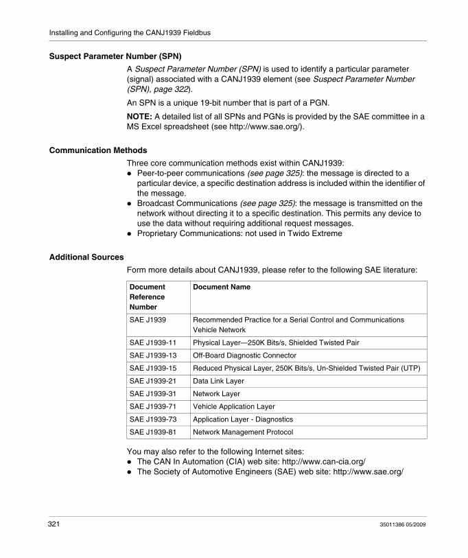
Installing and Configuring the CANJ1939 Fieldbus
Suspect Parameter Number (SPN)
A Suspect Parameter Number (SPN) is used to identify a particular parameter (signal) associated with a CANJ1939 element (see Suspect Parameter Number (SPN), page 322).
An SPN is a unique 19-bit number that is part of a PGN.
NOTE: A detailed list of all SPNs and PGNs is provided by the SAE committee in a MS Excel spreadsheet (see http://www.sae.org/).
Communication Methods
Three core communication methods exist within CANJ1939:Peer-to-peer communications (see page 325): the message is directed to a particular device, a specific destination address is included within the identifier of the message.Broadcast Communications (see page 325): the message is transmitted on the network without directing it to a specific destination. This permits any device to use the data without requiring additional request messages.Proprietary Communications: not used in Twido Extreme
Additional Sources
Form more details about CANJ1939, please refer to the following SAE literature:
You may also refer to the following Internet sites:The CAN In Automation (CIA) web site: http://www.can-cia.org/The Society of Automotive Engineers (SAE) web site: http://www.sae.org/
Document Reference Number
Document Name
SAE J1939 Recommended Practice for a Serial Control and Communications Vehicle Network
SAE J1939-11 Physical Layer—250K Bits/s, Shielded Twisted Pair
SAE J1939-13 Off-Board Diagnostic Connector
SAE J1939-15 Reduced Physical Layer, 250K Bits/s, Un-Shielded Twisted Pair (UTP)
SAE J1939-21 Data Link Layer
SAE J1939-31 Network Layer
SAE J1939-71 Vehicle Application Layer
SAE J1939-73 Application Layer - Diagnostics
SAE J1939-81 Network Management Protocol
321 35011386 05/2009

Installing and Configuring the CANJ1939 Fieldbus
CANJ19139 Parameter Group Number and Suspect Parameter Number
Introduction
This section presents information relating to the Parameter Group Number and Suspect Parameter Number usage on a CANJ1939 network.
Parameter Group (PG)
Parameter Group (PG) is a collection of parameters that are conveyed in a CANJ1939 message.
Parameter Groups include:commandsdatarequestsacknowledgmentsnegative-acknowledgments
The PG is not dependent on the source address field: any source is allowed to send any PG.
Parameter Group Number (PGN)
The Parameter Group Number (PGN) is a 24-bit representation that identifies a particular PG.
The PGN structure permits a total of up to 8672 different parameter groups. With the transmission of a parameter group, the PGN is coded in the CAN identifier.
Suspect Parameter Number (SPN)
A Suspect Parameter Number (SPN) is a 19-bit number used to identify a particular element, component, or parameter associated with an ECU (CANJ1939 element). This capability is especially useful for diagnostics, permitting an ECU which has detected an issue associated with a particular component, such as a sensor, to transmit a message identifying the inoperative component. SPNs are assigned by the SAE (Society of Automotive Engineers) Committee. The first 511 SPNs are reserved and will be later assigned to correspond to the exact same number as the Parameter Identifier (PID) of J1587.
Examples of SPNs
Engine coolant temperatureFuel temperatureEngine oil temperatureTurbo oil temperatureEngine intercooler temperature
35011386 05/2009 322
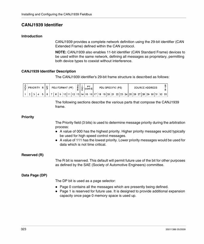
Installing and Configuring the CANJ1939 Fieldbus
CANJ1939 Identifier
Introduction
CANJ1939 provides a complete network definition using the 29-bit identifier (CAN Extended Frame) defined within the CAN protocol.
NOTE: CANJ1939 also enables 11-bit identifier (CAN Standard Frame) devices to be used within the same network, defining all messages as proprietary, permitting both device types to coexist without interference.
CANJ1939 Identifier Description
The CANJ1939 identifier's 29-bit frame structure is described as follows:
The following sections describe the various parts that compose the CANJ1939 frame.
Priority
The Priority field (3 bits) is used to determine message priority during the arbitration process:
A value of 000 has the highest priority. Higher priority messages would typically be used for high speed control messages.A value of 111 has the lowest priority. Lower priority messages would be used for data which is not time critical.
Reserved (R)
The R bit is reserved. This default will permit future use of the bit for other purposes as defined by the SAE (Society of Automotive Engineers) committee.
Data Page (DP)
The DP bit is used as a page selector:
Page 0 contains all the messages which are presently being defined.Page 1 is reserved for future use. It is designed to provide additional expansion capacity once page 0 memory space is used up.
323 35011386 05/2009
Installing and Configuring the CANJ1939 Fieldbus
PDU Format (PF)
The PF field (8 bits) identifies one of two message formats that can be transmitted:If 0 ≤ PF ≤ 239, then PDU1 format is used for peer-to-peer (see page 325) communication methods.If 240 ≤ PF ≤ 255, then PDU2 format is used for broadcast communication (see page 325) methods.
NOTE: PDU stands for Protocol Data Unit.
PDU Specific (PS)
The PS field (8 bits) is dependent on the value of the PDU:If PDU1 format is used then the PS field contains a Destination Address (DA). 240 Parameter Groups are provided in each data page of PDU1 formatIf PDU2 format is used then the PS field contains a Group Extension (GE). The Group Extension field, in conjunction with the four least significant bits of the PDU Format field, provide for 4096 Parameter Groups for each Data Page (DP)
Source Address
The Source Address field (8 bits) contains the unique address of the ECU (CANJ1939 element) transmitting the message.
Other Fields
SOF (Start Of Frame): The initial bit in a CAN frame used only to indicate the beginning of the frame.SRR (Substitute Remote Request): This bit is entirely defined and controlled by CAN and therefore not described or modified by CANJ1939.IDE (Identifier Extension Bit): This bit is entirely defined and controlled by CAN and therefore not described or modified by CANJ1939.RTR (Remote Transmission Request): This feature of CAN is not used in CANJ1939.
35011386 05/2009 324
Installing and Configuring the CANJ1939 Fieldbus
Communication on a CANJ1939 Network
Overview
This section provides details about collision detection, address assignment and communication methods on a CANJ1939 network.
Collision Detection
CANJ1939 uses the CAN protocol which permits any device to transmit a message on the network when the bus is idle.
Collisions are avoided due to the arbitration process that occurs while the identifier is transmitted (using a non-destructive arbitration scheme). Arbitration, permits high priority messages to get through with low latency (delay) times because there is equal access to the network by any device.
Address Assignment
For a given network, each network element address must be unique (0 to 254, 255 available for Broadcast). The PGNs are not Source Address dependent. Therefore any CANJ1939 element can transmit any message.
Broadcast
Most messages used on the CANJ1939 network are of the Broadcast type. This means that the data are transmitted over the network without directing it to a specific destination. This permits any device to use those data without requiring additional request messages. This also permits future software revisions to easily accommodate new devices (address assignments).
Peer to Peer
When a message must be directed to a particular device, a specific destination address can be included within the identifier of the message.
325 35011386 05/2009
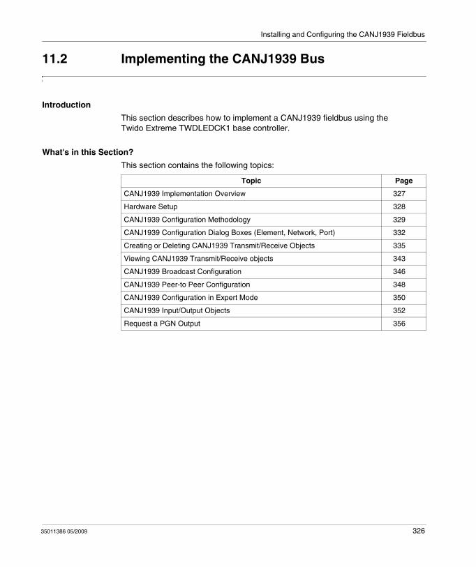
Installing and Configuring the CANJ1939 Fieldbus
11.2 Implementing the CANJ1939 Bus
Introduction
This section describes how to implement a CANJ1939 fieldbus using the Twido Extreme TWDLEDCK1 base controller.
What's in this Section?
This section contains the following topics:
Topic Page
CANJ1939 Implementation Overview 327
Hardware Setup 328
CANJ1939 Configuration Methodology 329
CANJ1939 Configuration Dialog Boxes (Element, Network, Port) 332
Creating or Deleting CANJ1939 Transmit/Receive Objects 335
Viewing CANJ1939 Transmit/Receive objects 343
CANJ1939 Broadcast Configuration 346
CANJ1939 Peer-to Peer Configuration 348
CANJ1939 Configuration in Expert Mode 350
CANJ1939 Input/Output Objects 352
Request a PGN Output 356
35011386 05/2009 326
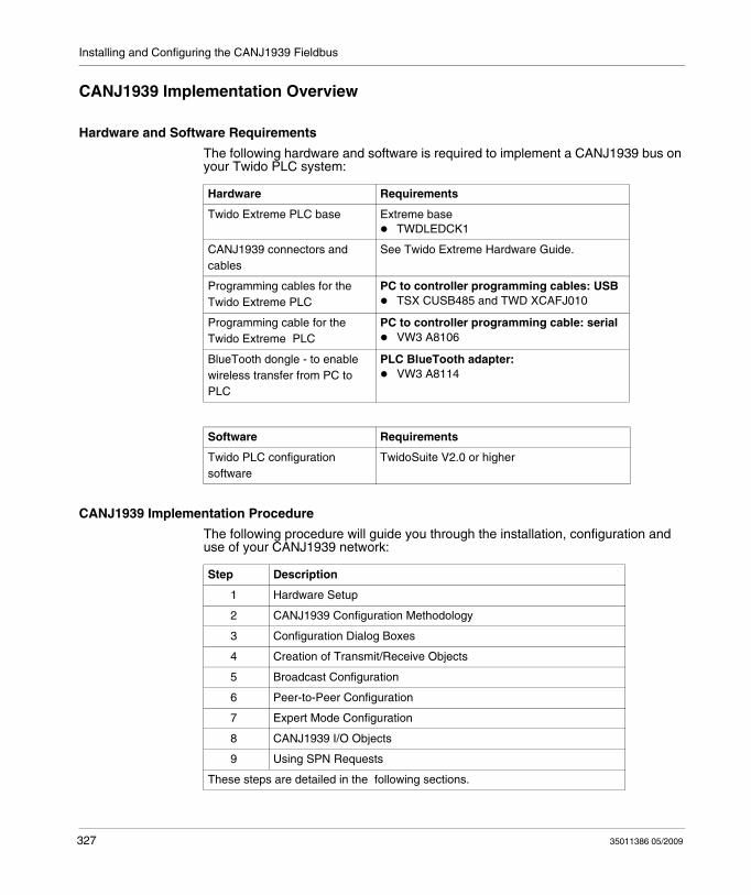
Installing and Configuring the CANJ1939 Fieldbus
CANJ1939 Implementation Overview
Hardware and Software Requirements
The following hardware and software is required to implement a CANJ1939 bus on your Twido PLC system:
CANJ1939 Implementation Procedure
The following procedure will guide you through the installation, configuration and use of your CANJ1939 network:
Hardware Requirements
Twido Extreme PLC base Extreme baseTWDLEDCK1
CANJ1939 connectors and cables
See Twido Extreme Hardware Guide.
Programming cables for the Twido Extreme PLC
PC to controller programming cables: USBTSX CUSB485 and TWD XCAFJ010
Programming cable for the Twido Extreme PLC
PC to controller programming cable: serialVW3 A8106
BlueTooth dongle - to enable wireless transfer from PC to PLC
PLC BlueTooth adapter:VW3 A8114
Software Requirements
Twido PLC configuration software
TwidoSuite V2.0 or higher
Step Description
1 Hardware Setup
2 CANJ1939 Configuration Methodology
3 Configuration Dialog Boxes
4 Creation of Transmit/Receive Objects
5 Broadcast Configuration
6 Peer-to-Peer Configuration
7 Expert Mode Configuration
8 CANJ1939 I/O Objects
9 Using SPN Requests
These steps are detailed in the following sections.
327 35011386 05/2009
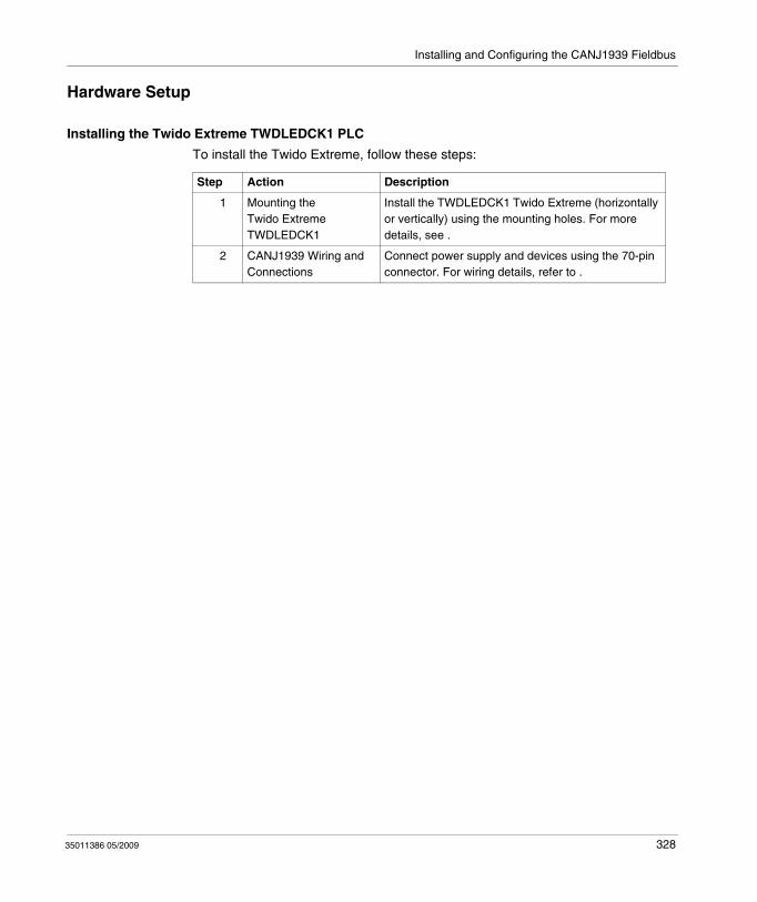
Installing and Configuring the CANJ1939 Fieldbus
Hardware Setup
Installing the Twido Extreme TWDLEDCK1 PLC
To install the Twido Extreme, follow these steps:
Step Action Description
1 Mounting the Twido Extreme TWDLEDCK1
Install the TWDLEDCK1 Twido Extreme (horizontally or vertically) using the mounting holes. For more details, see .
2 CANJ1939 Wiring and Connections
Connect power supply and devices using the 70-pin connector. For wiring details, refer to .
35011386 05/2009 328
Installing and Configuring the CANJ1939 Fieldbus
CANJ1939 Configuration Methodology
Overview
This section describes the general methodology for configuring the CANJ1939 bus. Further details are provided in subsequent sections.
CANJ1939 configuration is performed in the Describe window of TwidoSuite. The results of your configuration may be then viewed in Program → Configure the Hardware, Module Configuration CANJ1939 tab (see Viewing CANJ1939 Transmit/Receive objects, page 343).
NOTE:
1. CANJ1939 configuration can only be performed in Offline mode.2. No changes can be made when the Twido Extreme is connected to the PC. Only
the network name, element names and "Expert Mode" check box can be modified in Online mode.
329 35011386 05/2009
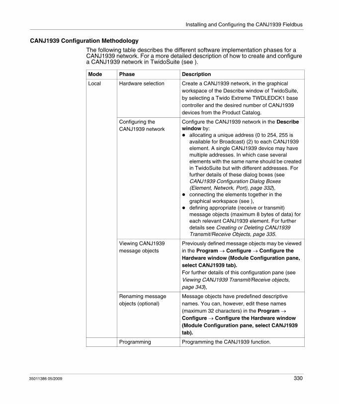
Installing and Configuring the CANJ1939 Fieldbus
CANJ1939 Configuration Methodology
The following table describes the different software implementation phases for a CANJ1939 network. For a more detailed description of how to create and configure a CANJ1939 network in TwidoSuite (see ).
Mode Phase Description
Local Hardware selection Create a CANJ1939 network, in the graphical workspace of the Describe window of TwidoSuite, by selecting a Twido Extreme TWDLEDCK1 base controller and the desired number of CANJ1939 devices from the Product Catalog.
Configuring the CANJ1939 network
Configure the CANJ1939 network in the Describe window by:
allocating a unique address (0 to 254, 255 is available for Broadcast) (2) to each CANJ1939 element. A single CANJ1939 device may have multiple addresses. In which case several elements with the same name should be created in TwidoSuite but with different addresses. For further details of these dialog boxes (see CANJ1939 Configuration Dialog Boxes (Element, Network, Port), page 332),connecting the elements together in the graphical workspace (see ),defining appropriate (receive or transmit) message objects (maximum 8 bytes of data) for each relevant CANJ1939 element. For further details see Creating or Deleting CANJ1939 Transmit/Receive Objects, page 335.
Viewing CANJ1939 message objects
Previously defined message objects may be viewed in the Program → Configure → Configure the Hardware window (Module Configuration pane, select CANJ1939 tab).For further details of this configuration pane (see Viewing CANJ1939 Transmit/Receive objects, page 343),
Renaming message objects (optional)
Message objects have predefined descriptive names. You can, however, edit these names (maximum 32 characters) in the Program → Configure → Configure the Hardware window (Module Configuration pane, select CANJ1939 tab).
Programming Programming the CANJ1939 function.
35011386 05/2009 330
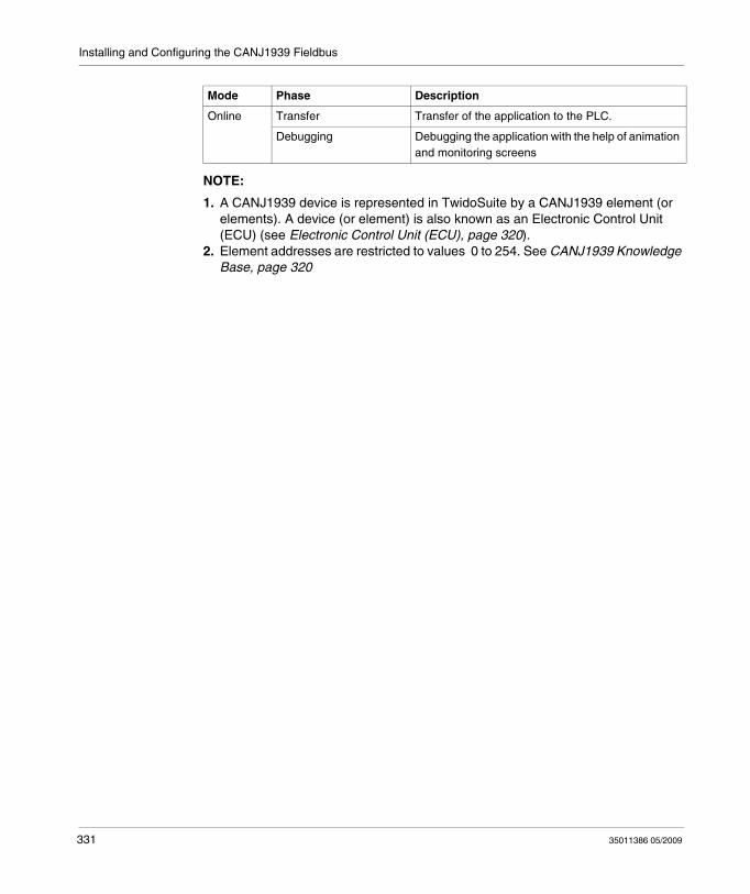
Installing and Configuring the CANJ1939 Fieldbus
NOTE:
1. A CANJ1939 device is represented in TwidoSuite by a CANJ1939 element (or elements). A device (or element) is also known as an Electronic Control Unit (ECU) (see Electronic Control Unit (ECU), page 320).
2. Element addresses are restricted to values 0 to 254. See CANJ1939 Knowledge Base, page 320
Online Transfer Transfer of the application to the PLC.
Debugging Debugging the application with the help of animation and monitoring screens
Mode Phase Description
331 35011386 05/2009
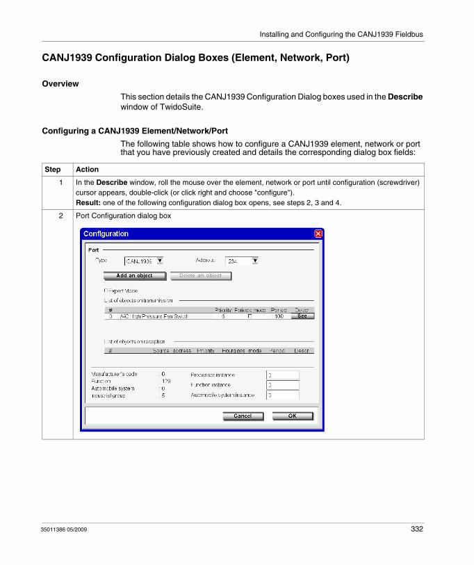
Installing and Configuring the CANJ1939 Fieldbus
CANJ1939 Configuration Dialog Boxes (Element, Network, Port)
Overview
This section details the CANJ1939 Configuration Dialog boxes used in the Describe window of TwidoSuite.
Configuring a CANJ1939 Element/Network/Port
The following table shows how to configure a CANJ1939 element, network or port that you have previously created and details the corresponding dialog box fields:
Step Action
1 In the Describe window, roll the mouse over the element, network or port until configuration (screwdriver) cursor appears, double-click (or click right and choose "configure").Result: one of the following configuration dialog box opens, see steps 2, 3 and 4.
2 Port Configuration dialog box
35011386 05/2009 332
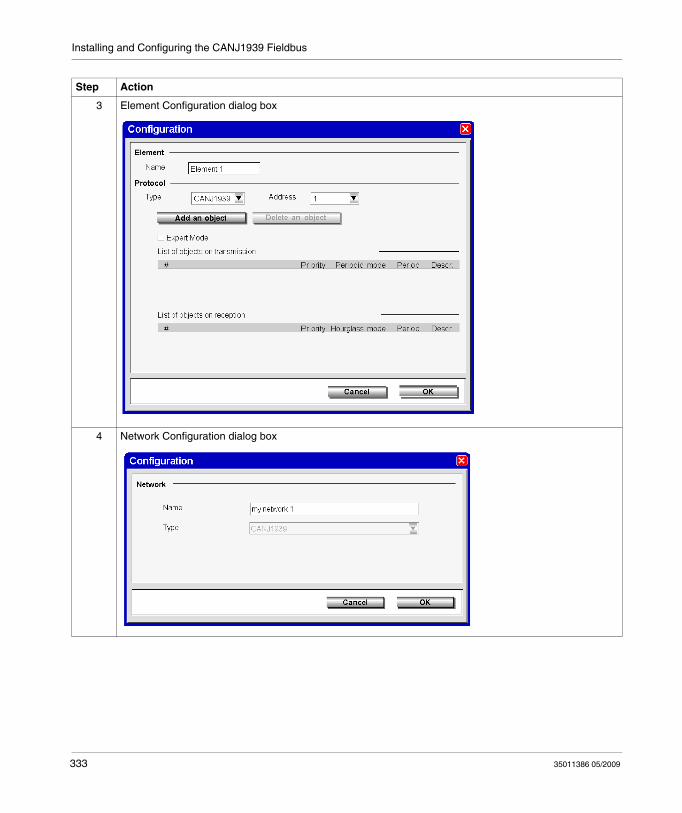
Installing and Configuring the CANJ1939 Fieldbus
3 Element Configuration dialog box
4 Network Configuration dialog box
Step Action
333 35011386 05/2009
Installing and Configuring the CANJ1939 Fieldbus
5 The following fields can be modified (optional):Name: the default name is "Element 1" (for element) and "My network 1"(for network) and this field is limited to 32 characters.Address: the default value is 0. Element addresses are restricted to values 0 to 255.Expert Mode check box: when this is selected the PGN/SPN numbers are displayed. By default this check box is cleared and even if you leave this box selected when you close this dialog box the default value (cleared) is reinstated when the dialog box is reopened. #: this takes values from 0 to 31 and provides a simple identification number for different types of messages (see Parameter Group Number (PGN), page 320). If two or more message objects come from the same parameter group, and thus share the same #, changing the # value for one object will automatically apply this value to the others. The table is also re-ordered to always display the objects in ascending # order. Priority: this takes values from 0 to 7(0 being the highest priority). These values are preset according to the particular message object (SPN) (see Suspect Parameter Number (SPN), page 321). These can be edited, however, and changing the priority for one message object results in attributing the same priority to all message objects that share the same #. Periodic mode (transmit objects) check box: when this is selected the message is sent periodically with the period (in ms) that you indicate in the Period field. If the periodic mode check box is cleared the period field cannot be edited. Changing the periodic mode for one message object results in applying the same mode to all message objects that share the same #.Hourglass mode(receive objects) check box: when this is selected the time (in ms) indicated in the Period field provides a time out period. (If the Twido Extreme does not receive a message after this time out period a Parameter Group error occurs.) System Words %SW33 to %SW40 are updated.Period: (in ms) this takes values from 10 to 60000 (default value is 100) and can only be edited if the corresponding periodic mode (transmit objects) or Time out (receive objects) check box is selected. Descr: press this button to display a description of the message object (SPN).
Processor instance: (1) indicates to the CANJ1939 element which PLC will send it messages. Authorized values are 0 and 1.
Function instance: (1) particular occurrence of a given function in an automobile system and given network. If only one instance of a certain Function exists in a network, then this field must be set to ‘0’ to define it as the first instance.
Automobile system instance: (1) particular occurrence of a given vehicle system in a given network. If only one instance of a certain automobile system exists in a network, then this field must be set to ‘0’ to define it as the first instance.
Note: (1)All these values are specified in SAE J1939.
6 The following fields are read-only:
Manufacturer’s code: (1) indicates the manufacturer in charge of the production of the electronic control module.
Function: (1) indicates the primary function of the Controller Application.
Automobile system: (1) a group of functions in a network.
Industrial group: (1)indicates an industry group
Note: (1)All these values are specified in SAE J1939.
7 Click Cancel to discard or OK to apply the changes and close the dialog box.
Step Action
35011386 05/2009 334
Installing and Configuring the CANJ1939 Fieldbus
Creating or Deleting CANJ1939 Transmit/Receive Objects
Overview
CANJ1939 messages can be either transmit or receive objects. These are created via the appropriate (element or port) configuration dialog box accessible from the Describe window. A transmit object is an object transmitted by the Twido Extreme and a receive object is one received by the Twido Extreme.
This section explains how to create and delete transmit/receive objects. Broadcast messages are defined by adding objects on a port. Peer-to-peer messages are defined by adding objects to the appropriate element(s). See Communication on a CANJ1939 Network, page 325.
NOTE: In TwidoSuite you can configure the CANJ1939 network for messages (broadcast or peer-to-peer) that are sent by the Twido Extreme PLC. TwidoSuite can only be used to configure Twido Extreme controllers. Other non-Twido products connected on the CANJ1939 network cannot be configured using TwidoSuite.
335 35011386 05/2009
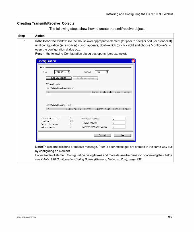
Installing and Configuring the CANJ1939 Fieldbus
Creating Transmit/Receive Objects
The following steps show how to create transmit/receive objects.
Step Action
1 In the Describe window, roll the mouse over appropriate element (for peer to peer) or port (for broadcast) until configuration (screwdriver) cursor appears, double-click (or click right and choose "configure") to open the configuration dialog box.Result: the following Configuration dialog box opens (port example).
Note:This example is for a broadcast message. Peer to peer messages are created in the same way but by configuring an element.For example of element Configuration dialog boxes and more detailed information concerning their fields see CANJ1939 Configuration Dialog Boxes (Element, Network, Port), page 332.
35011386 05/2009 336
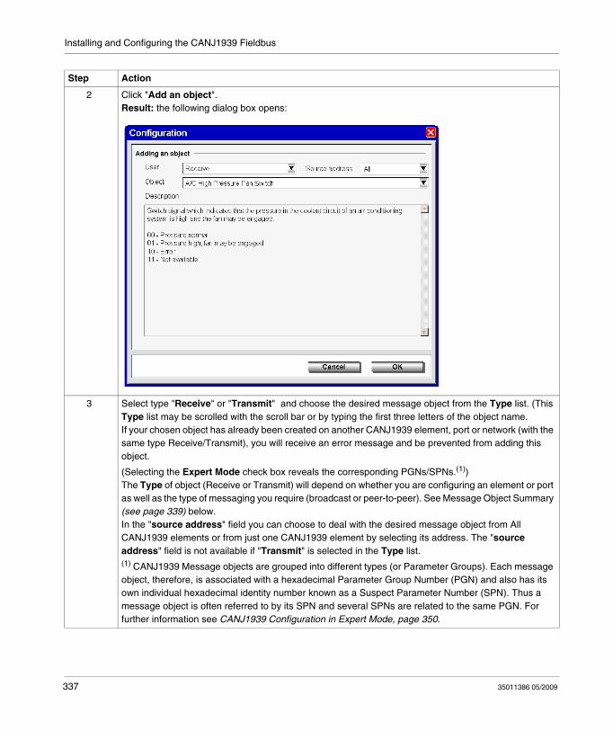
Installing and Configuring the CANJ1939 Fieldbus
2 Click "Add an object".Result: the following dialog box opens:
3 Select type "Receive" or "Transmit" and choose the desired message object from the Type list. (This Type list may be scrolled with the scroll bar or by typing the first three letters of the object name.If your chosen object has already been created on another CANJ1939 element, port or network (with the same type Receive/Transmit), you will receive an error message and be prevented from adding this object.
(Selecting the Expert Mode check box reveals the corresponding PGNs/SPNs.(1)) The Type of object (Receive or Transmit) will depend on whether you are configuring an element or port as well as the type of messaging you require (broadcast or peer-to-peer). See Message Object Summary (see page 339) below.In the "source address" field you can choose to deal with the desired message object from All CANJ1939 elements or from just one CANJ1939 element by selecting its address. The "source address" field is not available if "Transmit" is selected in the Type list.(1) CANJ1939 Message objects are grouped into different types (or Parameter Groups). Each message object, therefore, is associated with a hexadecimal Parameter Group Number (PGN) and also has its own individual hexadecimal identity number known as a Suspect Parameter Number (SPN). Thus a message object is often referred to by its SPN and several SPNs are related to the same PGN. For further information see CANJ1939 Configuration in Expert Mode, page 350.
Step Action
337 35011386 05/2009
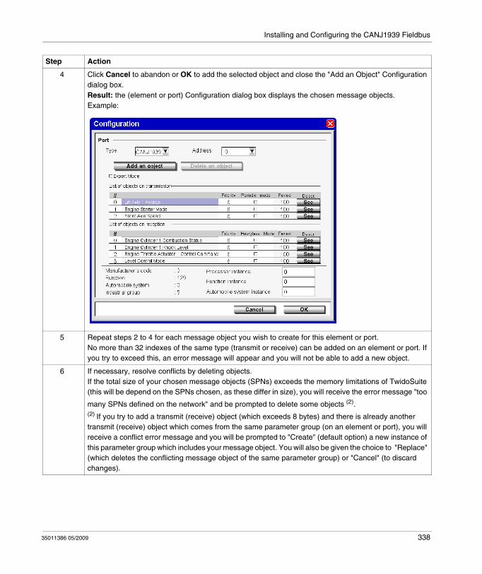
Installing and Configuring the CANJ1939 Fieldbus
4 Click Cancel to abandon or OK to add the selected object and close the "Add an Object" Configuration dialog box.Result: the (element or port) Configuration dialog box displays the chosen message objects.Example:
5 Repeat steps 2 to 4 for each message object you wish to create for this element or port.No more than 32 indexes of the same type (transmit or receive) can be added on an element or port. If you try to exceed this, an error message will appear and you will not be able to add a new object.
6 If necessary, resolve conflicts by deleting objects.If the total size of your chosen message objects (SPNs) exceeds the memory limitations of TwidoSuite (this will be depend on the SPNs chosen, as these differ in size), you will receive the error message "too
many SPNs defined on the network" and be prompted to delete some objects (2).(2) If you try to add a transmit (receive) object (which exceeds 8 bytes) and there is already another transmit (receive) object which comes from the same parameter group (on an element or port), you will receive a conflict error message and you will be prompted to "Create" (default option) a new instance of this parameter group which includes your message object. You will also be given the choice to "Replace" (which deletes the conflicting message object of the same parameter group) or "Cancel" (to discard changes).
Step Action
35011386 05/2009 338
Installing and Configuring the CANJ1939 Fieldbus
Message Object Summary
This table summarizes what it means to add transmit/receive objects on the CANJ1939 or on the CANJ1939 port.
Messages sent by other devices cannot be configured in TwidoSuite.
7 (Optional) You can manually edit certain fields in the (element or port) Configuration dialog box such as #, priority, periodic mode (for detailed explanation of these fields, see CANJ1939 Configuration Dialog Boxes (Element, Network, Port), page 332 If necessary, manually edit the # fields to assign new indexes for the created object groups (PGNs). Make sure that the created message objects have consecutive # indexes. For more information on the # field, see Message Object Indexes below.
8 Click Cancel to discard changes or click OK to save changes and close the Configuration dialog box.
Step Action
Transmit object added Receive object added
on an Element (Peer-to-Peer)
Twido Extreme sends a message to an element. (This enables the element to receive this message)
Twido Extreme will deal with this message if this element sends it
on the CANJ1939 Port (Broadcast)
Twido Extreme sends a message to an element configured to receive it (i.e., the element has the same message object declared as a transmit object)
Twido Extreme will deal with this message if it appears on the networkNote: you can configure Twido Extreme to deal with this message from All CANJ1939 elements or from just one CANJ1939 element
339 35011386 05/2009
Installing and Configuring the CANJ1939 Fieldbus
Message Object Indexes
The # field is a TwidoSuite index for the created object groups (PGNs) and takes values from 0 to 31. If two or more message objects come from the same parameter group, they will share the same #. Thus changing the # value for one object will automatically apply this value to the others. The table is also re-ordered to always display the objects in ascending # order. It is not possible to create a message object with an # index that has already been used by another element or port (TwidoSuite produces an error message in such cases). To resolve this, you can manually edit the # field and assign a new index number.
Note: To ensure that all the added SPNs are later accessible in the Program → Configure → Configure the Hardware (Module Configuration pane, CANJ1939 tab) window, make sure that the created message objects have consecutive # indexes. For example if you add 6 SPNs, they are automatically numbered #0 to #5. If you then delete the SPN with index #3, the SPNs #4 and #5 will not be visible in the configuration screen. To avoid this, manually edit the indexes #4 and #5 replacing them with indexes #3 and #4 to ensure a consecutive index list #0 to #4.
35011386 05/2009 340
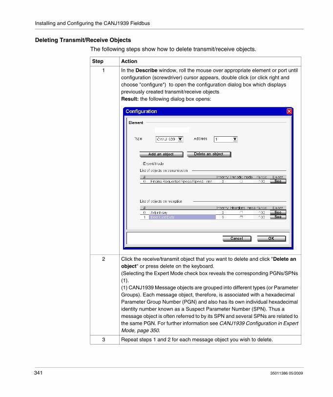
Installing and Configuring the CANJ1939 Fieldbus
Deleting Transmit/Receive Objects
The following steps show how to delete transmit/receive objects.
Step Action
1 In the Describe window, roll the mouse over appropriate element or port until configuration (screwdriver) cursor appears, double click (or click right and choose "configure") to open the configuration dialog box which displays previously created transmit/receive objects Result: the following dialog box opens:
2 Click the receive/transmit object that you want to delete and click "Delete an object" or press delete on the keyboard. (Selecting the Expert Mode check box reveals the corresponding PGNs/SPNs (1).(1) CANJ1939 Message objects are grouped into different types (or Parameter Groups). Each message object, therefore, is associated with a hexadecimal Parameter Group Number (PGN) and also has its own individual hexadecimal identity number known as a Suspect Parameter Number (SPN). Thus a message object is often referred to by its SPN and several SPNs are related to the same PGN. For further information see CANJ1939 Configuration in Expert Mode, page 350.
3 Repeat steps 1 and 2 for each message object you wish to delete.
341 35011386 05/2009
Installing and Configuring the CANJ1939 Fieldbus
4 After deleting message objects always make sure that the resulting indexes # are consecutive. This will ensure that all SPNs are later accessible in the Program → Configure → Configure the Hardware (Module Configuration pane, CANJ1939 tab) window. For example, if you add 6 SPNs, they are automatically numbered #0 to #5. If you then delete the SPN with index #3, the SPNs #4 and #5 will not be visible in the configuration screen. To avoid this, manually edit the indexes #4 and #5 replacing them with indexes #3 and #4 to ensure a consecutive index list #0 to #4.
5 Click Cancel to discard or OK to delete the selected object (s) and close the Configuration dialog box.
Step Action
35011386 05/2009 342
Installing and Configuring the CANJ1939 Fieldbus
Viewing CANJ1939 Transmit/Receive objects
Overview
This section explains how to view previously defined CANJ1939 message objects in the Program → Configure → Configure the Hardware window (Module Configuration pane, select CANJ1939 tab) of TwidoSuite and details the fields found in this pane.
NOTE: No actual configuration may be done in this window.
See (CANJ1939 Configuration Methodology, page 329) for general configuration information and see Creating or Deleting CANJ1939 Transmit/Receive Objects, page 335 to add and delete message objects.
343 35011386 05/2009
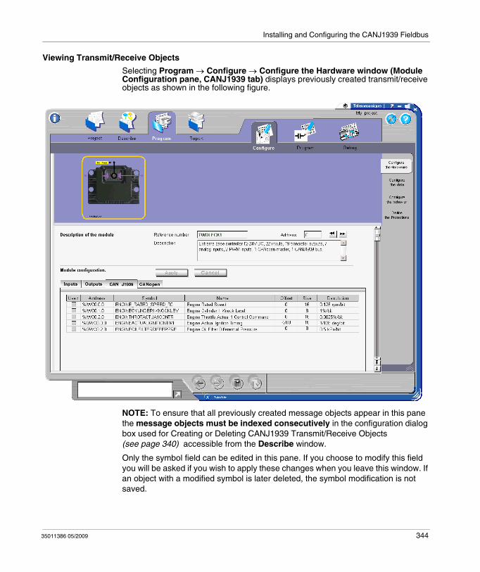
Installing and Configuring the CANJ1939 Fieldbus
Viewing Transmit/Receive Objects
Selecting Program → Configure → Configure the Hardware window (Module Configuration pane, CANJ1939 tab) displays previously created transmit/receive objects as shown in the following figure.
NOTE: To ensure that all previously created message objects appear in this pane the message objects must be indexed consecutively in the configuration dialog box used for Creating or Deleting CANJ1939 Transmit/Receive Objects (see page 340) accessible from the Describe window.
Only the symbol field can be edited in this pane. If you choose to modify this field you will be asked if you wish to apply these changes when you leave this window. If an object with a modified symbol is later deleted, the symbol modification is not saved.
35011386 05/2009 344

Installing and Configuring the CANJ1939 Fieldbus
For more information concerning the address field see CANJ1939 Input/Output Objects, page 352.
If an SPN is smaller than 8 bits, ":Xi" is appended to the address to provide the starting position of the SPN in the word.
345 35011386 05/2009
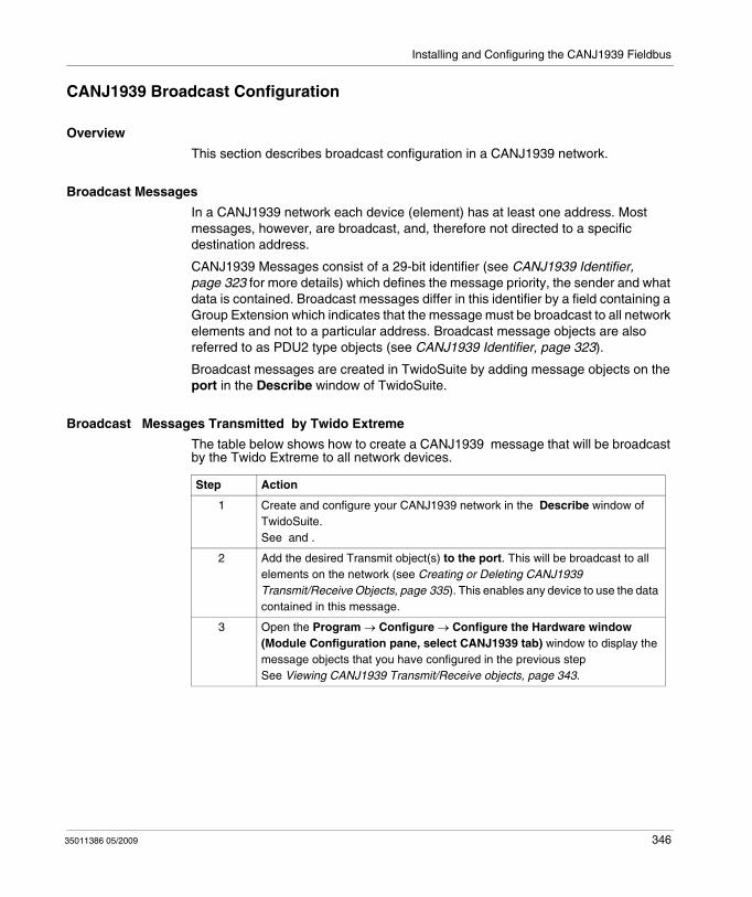
Installing and Configuring the CANJ1939 Fieldbus
CANJ1939 Broadcast Configuration
Overview
This section describes broadcast configuration in a CANJ1939 network.
Broadcast Messages
In a CANJ1939 network each device (element) has at least one address. Most messages, however, are broadcast, and, therefore not directed to a specific destination address.
CANJ1939 Messages consist of a 29-bit identifier (see CANJ1939 Identifier, page 323 for more details) which defines the message priority, the sender and what data is contained. Broadcast messages differ in this identifier by a field containing a Group Extension which indicates that the message must be broadcast to all network elements and not to a particular address. Broadcast message objects are also referred to as PDU2 type objects (see CANJ1939 Identifier, page 323).
Broadcast messages are created in TwidoSuite by adding message objects on the port in the Describe window of TwidoSuite.
Broadcast Messages Transmitted by Twido Extreme
The table below shows how to create a CANJ1939 message that will be broadcast by the Twido Extreme to all network devices.
Step Action
1 Create and configure your CANJ1939 network in the Describe window of TwidoSuite.See and .
2 Add the desired Transmit object(s) to the port. This will be broadcast to all elements on the network (see Creating or Deleting CANJ1939 Transmit/Receive Objects, page 335). This enables any device to use the data contained in this message.
3 Open the Program → Configure → Configure the Hardware window (Module Configuration pane, select CANJ1939 tab) window to display the message objects that you have configured in the previous stepSee Viewing CANJ1939 Transmit/Receive objects, page 343.
35011386 05/2009 346
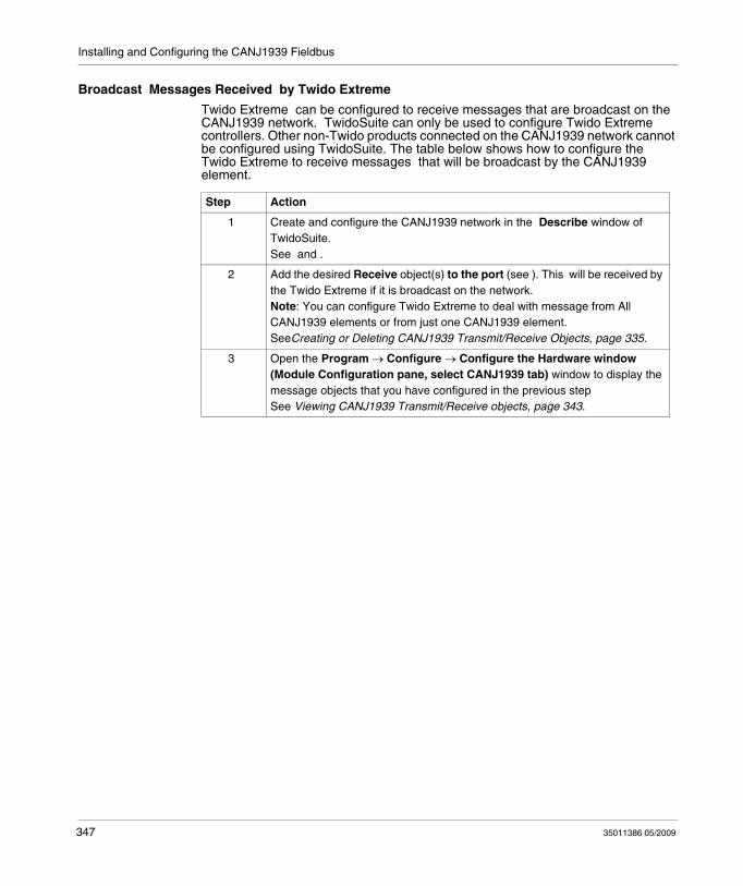
Installing and Configuring the CANJ1939 Fieldbus
Broadcast Messages Received by Twido Extreme
Twido Extreme can be configured to receive messages that are broadcast on the CANJ1939 network. TwidoSuite can only be used to configure Twido Extreme controllers. Other non-Twido products connected on the CANJ1939 network cannot be configured using TwidoSuite. The table below shows how to configure the Twido Extreme to receive messages that will be broadcast by the CANJ1939 element.
Step Action
1 Create and configure the CANJ1939 network in the Describe window of TwidoSuite.See and .
2 Add the desired Receive object(s) to the port (see ). This will be received by the Twido Extreme if it is broadcast on the network. Note: You can configure Twido Extreme to deal with message from All CANJ1939 elements or from just one CANJ1939 element.SeeCreating or Deleting CANJ1939 Transmit/Receive Objects, page 335.
3 Open the Program → Configure → Configure the Hardware window (Module Configuration pane, select CANJ1939 tab) window to display the message objects that you have configured in the previous stepSee Viewing CANJ1939 Transmit/Receive objects, page 343.
347 35011386 05/2009
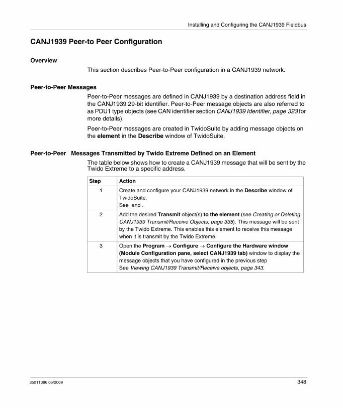
Installing and Configuring the CANJ1939 Fieldbus
CANJ1939 Peer-to Peer Configuration
Overview
This section describes Peer-to-Peer configuration in a CANJ1939 network.
Peer-to-Peer Messages
Peer-to-Peer messages are defined in CANJ1939 by a destination address field in the CANJ1939 29-bit identifier. Peer-to-Peer message objects are also referred to as PDU1 type objects (see CAN identifier section CANJ1939 Identifier, page 323 for more details).
Peer-to-Peer messages are created in TwidoSuite by adding message objects on the element in the Describe window of TwidoSuite.
Peer-to-Peer Messages Transmitted by Twido Extreme Defined on an Element
The table below shows how to create a CANJ1939 message that will be sent by the Twido Extreme to a specific address.
Step Action
1 Create and configure your CANJ1939 network in the Describe window of TwidoSuite.See and .
2 Add the desired Transmit object(s) to the element (see Creating or Deleting CANJ1939 Transmit/Receive Objects, page 335). This message will be sent by the Twido Extreme. This enables this element to receive this message when it is transmit by the Twido Extreme.
3 Open the Program → Configure → Configure the Hardware window (Module Configuration pane, select CANJ1939 tab) window to display the message objects that you have configured in the previous stepSee Viewing CANJ1939 Transmit/Receive objects, page 343.
35011386 05/2009 348

Installing and Configuring the CANJ1939 Fieldbus
Peer-to-Peer Messages Received by Twido Extreme Defined on an Element
Twido Extreme can be configured to receive messages that are sent by another device (Peer-to-Peer) on the CANJ1939 network. TwidoSuite can only be used to configure Twido Extreme controllers. Other non-Twido products connected on the CANJ1939 network cannot be configured using TwidoSuite. The table below shows how to configure the Twido Extreme to receive messages that are sent by another device (Peer-to-Peer) on the CANJ1939 network.
Messages Sent by Other Devices
Only messages sent by the Twido Extreme can be created in TwidoSuite. Messages sent by other CANJ1939 elements (devices) cannot be configured in TwidoSuite. These must be created in the device firmware.
Step Action
1 Create and configure your CANJ1939 network in the Describe window of TwidoSuite.See and .
2 Add the desired Receive object(s) to the element (see Creating or Deleting CANJ1939 Transmit/Receive Objects, page 335). This will be received by the Twido Extreme if it is sent by this element.
3 Open the Program → Configure → Configure the Hardware window (Module Configuration pane, select CANJ1939 tab) window to display the message objects that you have configured in the previous stepSee Viewing CANJ1939 Transmit/Receive objects, page 343.
349 35011386 05/2009

Installing and Configuring the CANJ1939 Fieldbus
CANJ1939 Configuration in Expert Mode
Overview
CANJ1939 configuration involves adding appropriate transmit or receive objects on elements in the network. See Creating or Deleting CANJ1939 Transmit/Receive Objects, page 335. This can also be done in expert mode (by selecting the Expert Mode check box in the Configuration dialog box). This section explains the use of this mode.
Selecting Expert Mode
In the TwidoSuite Describe Window, double-click the network, element or port that you wish to configure to open the Configuration dialog box. Select the Expert Mode check box.
Result: The Add/Delete an Object buttons are now called Add/Delete an SPN. The corresponding PGNs/SPNs are revealed. All objects that are added are displayed with their PGNs and SPNs.
PGNs and SPNs
CANJ1939 Message objects are grouped into different types (or Parameter Groups). Each message object, therefore, is associated with a hexadecimal Parameter Group Number (PGN) and also has its own individual hexadecimal identity number known as a Suspect Parameter Number (SPN). Thus a message object is often referred to by its SPN and several SPNs are related to the same PGN. For further information see CANJ19139 Parameter Group Number and Suspect Parameter Number, page 322
SPN Request
A particular use of the Expert Mode is to request specific information from a CANJ1939 element on the network. This is done by adding a particular Transmit SPN to the CANJ1939 element and by assigning this SPN value to the %IWC in the ladder/list program. See Request a PGN Output, page 356 for an example.
35011386 05/2009 350

Installing and Configuring the CANJ1939 Fieldbus
CAN J1939 User Objects
The I/O objects are:
%IWC0.i.j, %QWC0.i.j (word format - there are no I/O bits)%IWCD0.i.j, %QWCD0.i.j (double word format)%IWCF0.i.j, %QWC0.i.j (floating point format)
where
i is the SPN index (# in the Describe Configuration dialog box) i = 0,..., 31j is the channel number (the position (in bytes) of the SPN) j = 0,...7 (for word); j = 0,...,6 (otherwise)
The double word and floating point format I/Os ( %IWCD, %QWCD and %IWCF, %QWCF) have the same structure as the double word and floating point internal memory objects (%MD and %MF). For more information see CANJ1939 Input/Output Objects, page 352.
351 35011386 05/2009
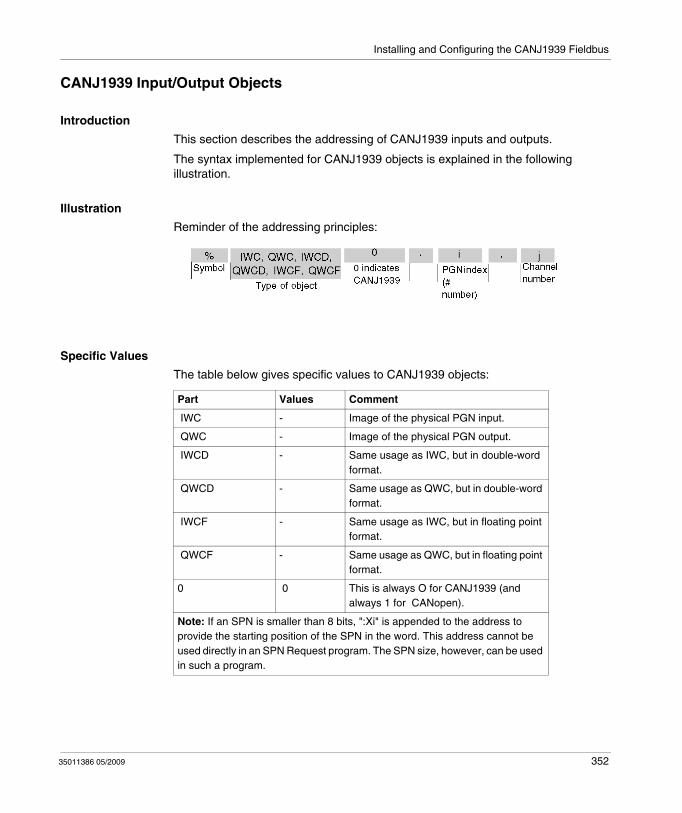
Installing and Configuring the CANJ1939 Fieldbus
CANJ1939 Input/Output Objects
Introduction
This section describes the addressing of CANJ1939 inputs and outputs.
The syntax implemented for CANJ1939 objects is explained in the following illustration.
Illustration
Reminder of the addressing principles:
Specific Values
The table below gives specific values to CANJ1939 objects:
Part Values Comment
IWC - Image of the physical PGN input.
QWC - Image of the physical PGN output.
IWCD - Same usage as IWC, but in double-word format.
QWCD - Same usage as QWC, but in double-word format.
IWCF - Same usage as IWC, but in floating point format.
QWCF - Same usage as QWC, but in floating point format.
0 0 This is always O for CANJ1939 (and always 1 for CANopen).
Note: If an SPN is smaller than 8 bits, ":Xi" is appended to the address to provide the starting position of the SPN in the word. This address cannot be used directly in an SPN Request program. The SPN size, however, can be used in such a program.
35011386 05/2009 352
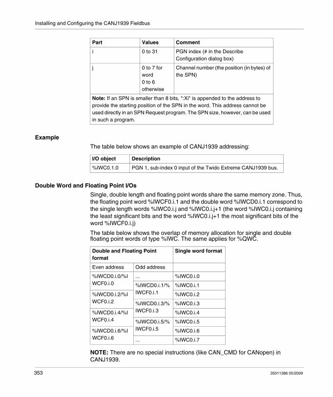
Installing and Configuring the CANJ1939 Fieldbus
Example
The table below shows an example of CANJ1939 addressing:
Double Word and Floating Point I/Os
Single, double length and floating point words share the same memory zone. Thus, the floating point word %IWCF0.i.1 and the double word %IWCD0.i.1 correspond to the single length words %IWC0.i.j and %IWC0.i.j+1 (the word %IWC0.i.j containing the least significant bits and the word %IWC0.i.j+1 the most significant bits of the word %IWCF0.i.j)
The table below shows the overlap of memory allocation for single and double floating point words of type %IWC. The same applies for %QWC.
NOTE: There are no special instructions (like CAN_CMD for CANopen) in CANJ1939.
i 0 to 31 PGN index (# in the Describe Configuration dialog box)
j 0 to 7 for word0 to 6 otherwise
Channel number (the position (in bytes) of the SPN)
Part Values Comment
Note: If an SPN is smaller than 8 bits, ":Xi" is appended to the address to provide the starting position of the SPN in the word. This address cannot be used directly in an SPN Request program. The SPN size, however, can be used in such a program.
I/O object Description
%IWC0.1.0 PGN 1, sub-index 0 input of the Twido Extreme CANJ1939 bus.
Double and Floating Point format
Single word format
Even address Odd address
%IWCD0.i.0/%IWCF0.i.0
... %IWC0.i.0
%IWCD0.i.1/%IWCF0.i.1
%IWC0.i.1
%IWCD0.i.2/%IWCF0.i.2
%IWC0.i.2
%IWCD0.i.3/%IWCF0.i.3
%IWC0.i.3
%IWCD0.i.4/%IWCF0.i.4
%IWC0.i.4
%IWCD0.i.5/%IWCF0.i.5
%IWC0.i.5
%IWCD0.i.6/%IWCF0.i.6
%IWC0.i.6
... %IWC0.i.7
353 35011386 05/2009
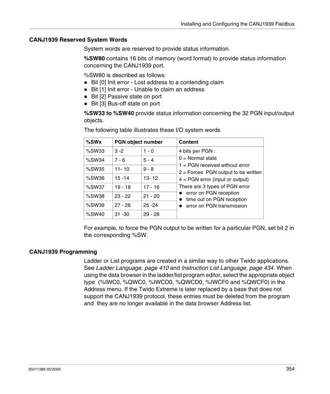
Installing and Configuring the CANJ1939 Fieldbus
CANJ1939 Reserved System Words
System words are reserved to provide status information.
%SW80 contains 16 bits of memory (word format) to provide status information concerning the CANJ1939 port.
%SW80 is described as follows:Bit [0] Init error - Lost address to a contending claimBit [1] Init error - Unable to claim an addressBit [2] Passive state on portBit [3] Bus-off state on port
%SW33 to %SW40 provide status information concerning the 32 PGN input/output objects.
The following table illustrates these I/O system words
For example, to force the PGN output to be written for a particular PGN, set bit 2 in the corresponding %SW.
CANJ1939 Programming
Ladder or List programs are created in a similar way to other Twido applications. See Ladder Language, page 410 and Instruction List Language, page 434. When using the data browser in the ladder/list program editor, select the appropriate object type (%IWC0, %QWC0, %IWCD0, %QWCD0, %IWCF0 and %QWCF0) in the Address menu. If the Twido Extreme is later replaced by a base that does not support the CANJ1939 protocol, these entries must be deleted from the program and they are no longer available in the data browser Address list.
%SWx PGN object number Content
%SW33 3 -2 1 - 0 4 bits per PGN :0 = Normal state1 = PGN received without error2 = Forces PGN output to be written4 = PGN error (input or output)There are 3 types of PGN error
error on PGN receptiontime out on PGN receptionerror on PGN transmission
%SW34 7 - 6 5 - 4
%SW35 11- 10 9 - 8
%SW36 15 -14 13- 12
%SW37 19 - 18 17 - 16
%SW38 23 - 22 21 - 20
%SW39 27 - 26 25 -24
%SW40 31 -30 29 - 28
35011386 05/2009 354

Installing and Configuring the CANJ1939 Fieldbus
CANJ19393 Error messages
The following conditions will produce error messages in a program concerning CANJ1939 I/O objects:
When entering an object (%IWC0, %QWC0, %IWCD0, %QWCD0, %IWCF0 and %QWCF0) the SPN number i (0 to 31) or channel number j (0 to 7) is out of range.The PLC chosen in the Describe window does not support the CANJ1939 protocol.There is no SPN defined at address i, channel j.
355 35011386 05/2009
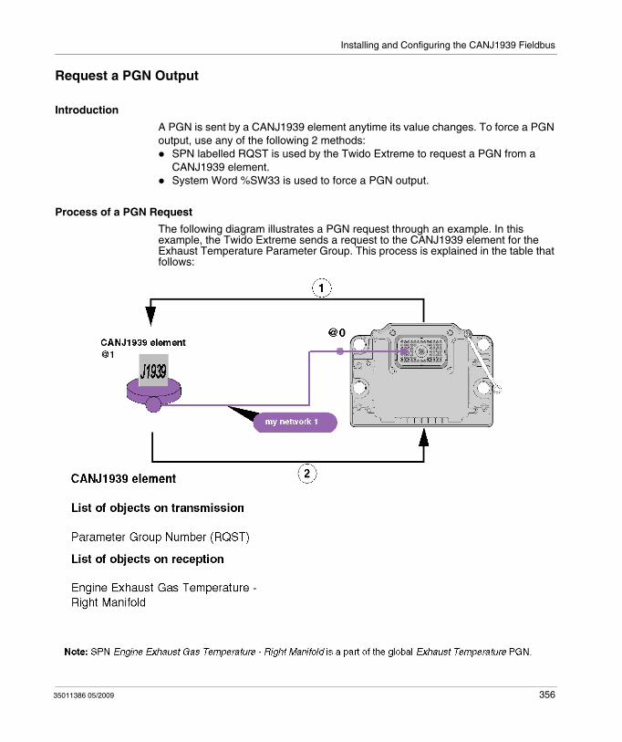
Installing and Configuring the CANJ1939 Fieldbus
Request a PGN Output
Introduction
A PGN is sent by a CANJ1939 element anytime its value changes. To force a PGN output, use any of the following 2 methods:
SPN labelled RQST is used by the Twido Extreme to request a PGN from a CANJ1939 element.System Word %SW33 is used to force a PGN output.
Process of a PGN Request
The following diagram illustrates a PGN request through an example. In this example, the Twido Extreme sends a request to the CANJ1939 element for the Exhaust Temperature Parameter Group. This process is explained in the table that follows:
35011386 05/2009 356

Installing and Configuring the CANJ1939 Fieldbus
The table below details the process of a PGN request:
Using SPN RQST
To use the SPN RQST method, configure the CANJ1939 Network as detailed below in the following example:
Stage Description
1 Twido Extreme sends a SPN RQST to a CANJ1939 element to request the value of the PGN Exhaust Temperature
2 The CANJ1939 element sends the value of the PGN requested (Exhaust Temperature)
Step Action Window location in TwidoSuite
1 Create a CANJ1939 network with a CANJ1939 element.For further details on how to create a CANJ1939 network, see .
Describe
2 On the CANJ1939 element:Add the Parameter Group Number (RQST) transmit SPN. For further details on how to define appropriate (receive or transmit) SPN, see Creating or Deleting CANJ1939 Transmit/Receive Objects, page 335. Add the receive SPN that you want to request (for example Engine Exhaust Gas Temperature - Right Manifold). For further details on how to define appropriate (receive or transmit) SPN, see Creating or Deleting CANJ1939 Transmit/Receive Objects, page 335.
Describe
3 On the CANJ1939 element:1. Right-click and select configuration.2. Select the Expert Mode check box.3. Record the PGN you want to request. (For example, the number of
the Parameter Group Exhaust Temperature is 65031)
Describe
4 Record the address of the output exchange word (%QWCD0.y.z) assigned to the SPN RQST that you have added in the previous step.
Program → Configure → Configure the hardware → CANJ1939 tab → Address field
5 Assign the PGN you want to force to the output exchange word %QWCD0.y.z recorded.Example: to make a request on the PG Exhaust Temperature (PGN=65031(16#FE07)), use the list instruction:%QWC0.0.0 := 16#FE07Note: You can also adjust %QWCD0.y.z online using the animation table.
Program → Program → Edit Program
Note: If the parameter requested is not available, the CANJ1939 element send a Non-ACKnowledgement (NACK) to the Twido Extreme.
357 35011386 05/2009
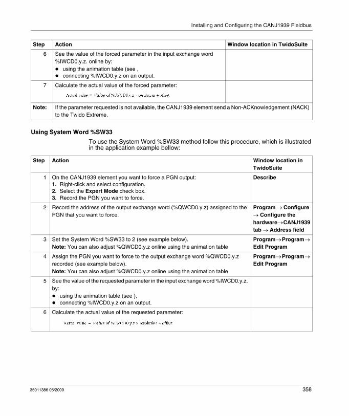
Installing and Configuring the CANJ1939 Fieldbus
Using System Word %SW33
To use the System Word %SW33 method follow this procedure, which is illustrated in the application example bellow:
6 See the value of the forced parameter in the input exchange word %IWCD0.y.z. online by:
using the animation table (see ,connecting %IWCD0.y.z on an output.
7 Calculate the actual value of the forced parameter:
Step Action Window location in TwidoSuite
Note: If the parameter requested is not available, the CANJ1939 element send a Non-ACKnowledgement (NACK) to the Twido Extreme.
Step Action Window location in TwidoSuite
1 On the CANJ1939 element you want to force a PGN output:1. Right-click and select configuration.2. Select the Expert Mode check box.3. Record the PGN you want to force.
Describe
2 Record the address of the output exchange word (%QWCD0.y.z) assigned to the PGN that you want to force.
Program → Configure → Configure the hardware → CANJ1939 tab → Address field
3 Set the System Word %SW33 to 2 (see example below).Note: You can also adjust %QWCD0.y.z online using the animation table
Program → Program → Edit Program
4 Assign the PGN you want to force to the output exchange word %QWCD0.y.z recorded (see example below).Note: You can also adjust %QWCD0.y.z online using the animation table
Program → Program → Edit Program
5 See the value of the requested parameter in the input exchange word %IWCD0.y.z. by:
using the animation table (see ),connecting %IWCD0.y.z on an output.
6 Calculate the actual value of the requested parameter:
35011386 05/2009 358
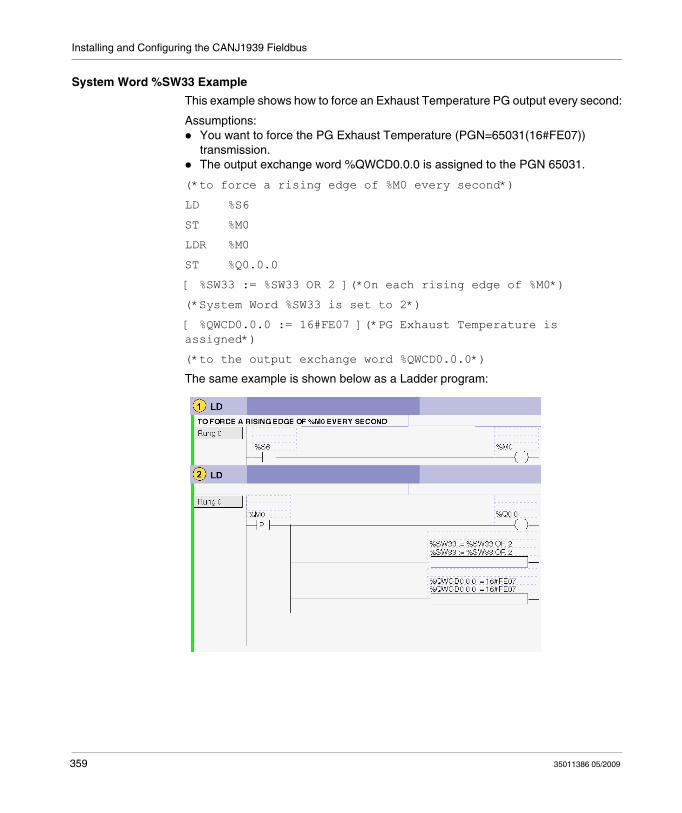
Installing and Configuring the CANJ1939 Fieldbus
System Word %SW33 Example
This example shows how to force an Exhaust Temperature PG output every second:
Assumptions:You want to force the PG Exhaust Temperature (PGN=65031(16#FE07)) transmission.The output exchange word %QWCD0.0.0 is assigned to the PGN 65031.
(*to force a rising edge of %M0 every second*)
LD %S6
ST %M0
LDR %M0
ST %Q0.0.0
[ %SW33 := %SW33 OR 2 ](*On each rising edge of %M0*)
(*System Word %SW33 is set to 2*)
[ %QWCD0.0.0 := 16#FE07 ](*PG Exhaust Temperature is assigned*)
(*to the output exchange word %QWCD0.0.0*)
The same example is shown below as a Ladder program:
359 35011386 05/2009
35011386 05/2009
12
Configuring the TwidoPort Ethernet Gateway
35011386 05/2009
Configuring the TwidoPort Ethernet Gateway
Subject of this Chapter
This chapter provides information on the software configuration of the ConneXium TwidoPort Ethernet Gateway module.
What's in this Chapter?
This chapter contains the following sections:
Section Topic Page
12.1 Normal Configuration and Connection of TwidoPort 361
12.2 TwidoPort’s Telnet Configuration 370
12.3 Communication Features 385
360
Configuring the TwidoPort Ethernet Gateway
12.1 Normal Configuration and Connection of TwidoPort
Subject of this Section
This section provides information on how to perform a normal configuration of the ConneXium TwidoPort module with the TwidoSuite application program, module connectivity and BootP configuration information, as well.
What's in this Section?
This section contains the following topics:
Topic Page
Normal Configuration with TwidoSuite 362
BootP Configuration 369
361 35011386 05/2009
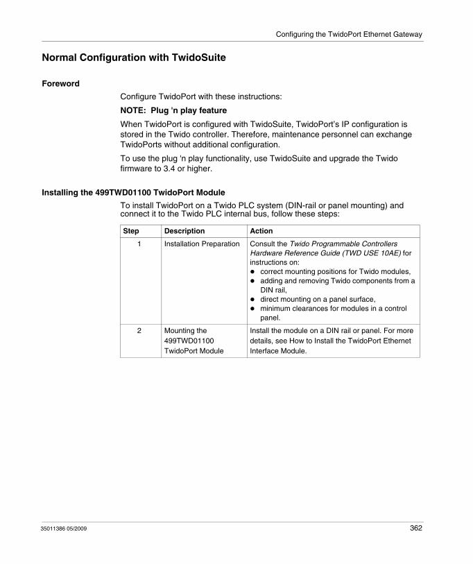
Configuring the TwidoPort Ethernet Gateway
Normal Configuration with TwidoSuite
Foreword
Configure TwidoPort with these instructions:
NOTE: Plug 'n play feature
When TwidoPort is configured with TwidoSuite, TwidoPort’s IP configuration is stored in the Twido controller. Therefore, maintenance personnel can exchange TwidoPorts without additional configuration.
To use the plug 'n play functionality, use TwidoSuite and upgrade the Twido firmware to 3.4 or higher.
Installing the 499TWD01100 TwidoPort Module
To install TwidoPort on a Twido PLC system (DIN-rail or panel mounting) and connect it to the Twido PLC internal bus, follow these steps:
Step Description Action
1 Installation Preparation Consult the Twido Programmable Controllers Hardware Reference Guide (TWD USE 10AE) for instructions on:
correct mounting positions for Twido modules,adding and removing Twido components from a DIN rail,direct mounting on a panel surface,minimum clearances for modules in a control panel.
2 Mounting the 499TWD01100 TwidoPort Module
Install the module on a DIN rail or panel. For more details, see How to Install the TwidoPort Ethernet Interface Module.
35011386 05/2009 362
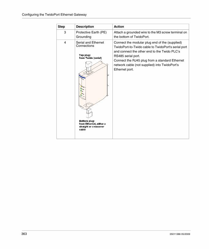
Configuring the TwidoPort Ethernet Gateway
3 Protective Earth (PE) Grounding
Attach a grounded wire to the M3 screw terminal on the bottom of TwidoPort.
4 Serial and Ethernet Connections
Connect the modular plug end of the (supplied) TwidoPort-to-Twido cable to TwidoPort's serial port and connect the other end to the Twido PLC’s RS485 serial port.Connect the RJ45 plug from a standard Ethernet network cable (not supplied) into TwidoPort’s Ethernet port.
Step Description Action
363 35011386 05/2009
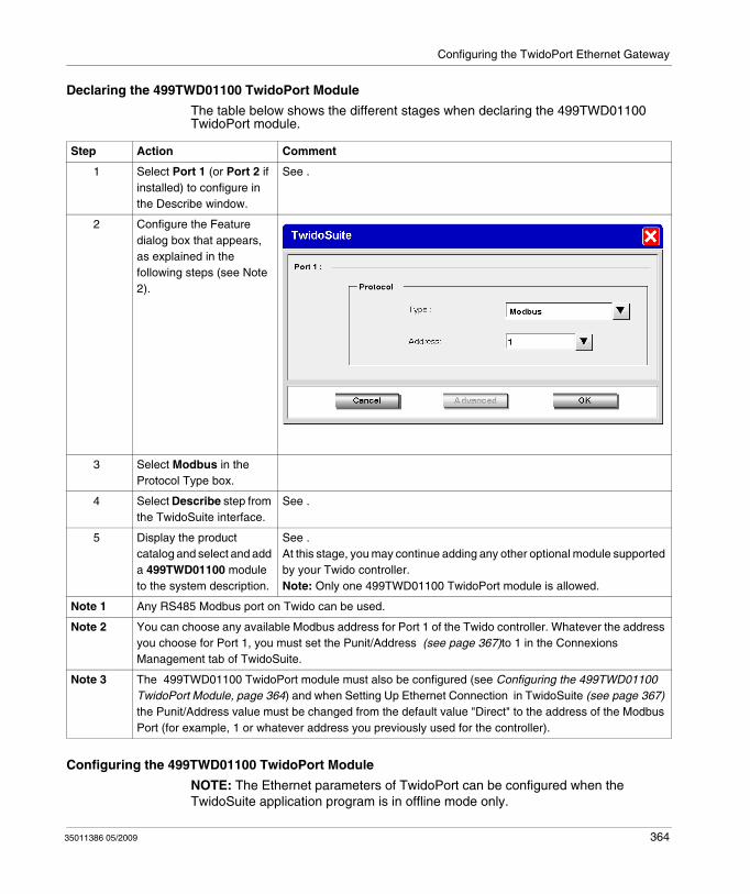
Configuring the TwidoPort Ethernet Gateway
Declaring the 499TWD01100 TwidoPort Module
The table below shows the different stages when declaring the 499TWD01100 TwidoPort module.
Configuring the 499TWD01100 TwidoPort Module
NOTE: The Ethernet parameters of TwidoPort can be configured when the TwidoSuite application program is in offline mode only.
Step Action Comment
1 Select Port 1 (or Port 2 if installed) to configure in the Describe window.
See .
2 Configure the Feature dialog box that appears, as explained in the following steps (see Note 2).
3 Select Modbus in the Protocol Type box.
4 Select Describe step from the TwidoSuite interface.
See .
5 Display the product catalog and select and add a 499TWD01100 module to the system description.
See .At this stage, you may continue adding any other optional module supported by your Twido controller.Note: Only one 499TWD01100 TwidoPort module is allowed.
Note 1 Any RS485 Modbus port on Twido can be used.
Note 2 You can choose any available Modbus address for Port 1 of the Twido controller. Whatever the address you choose for Port 1, you must set the Punit/Address (see page 367)to 1 in the Connexions Management tab of TwidoSuite.
Note 3 The 499TWD01100 TwidoPort module must also be configured (see Configuring the 499TWD01100 TwidoPort Module, page 364) and when Setting Up Ethernet Connection in TwidoSuite (see page 367) the Punit/Address value must be changed from the default value "Direct" to the address of the Modbus Port (for example, 1 or whatever address you previously used for the controller).
35011386 05/2009 364
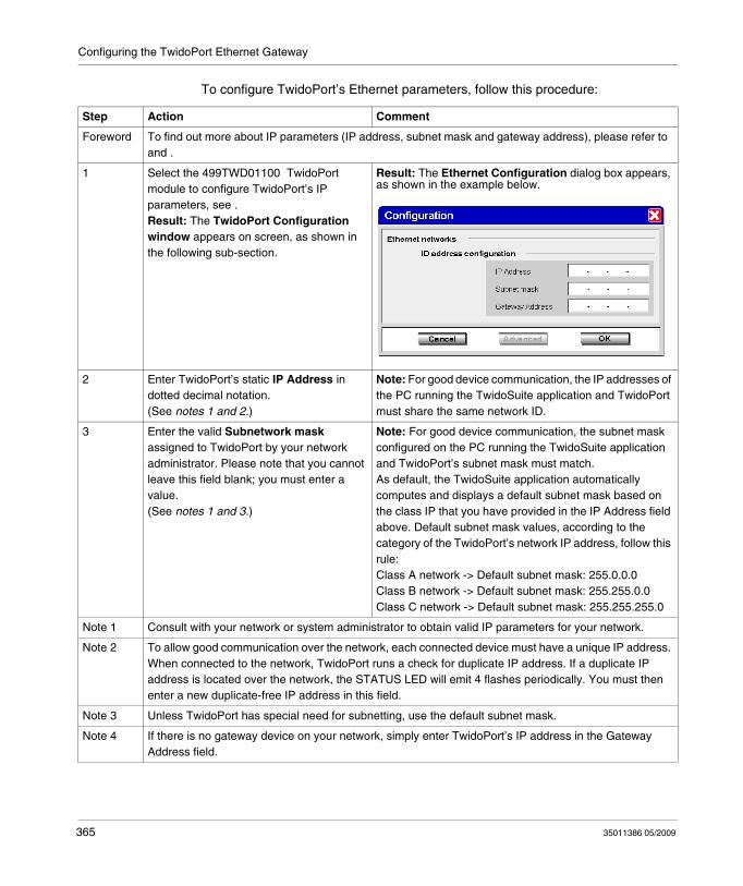
Configuring the TwidoPort Ethernet Gateway
To configure TwidoPort’s Ethernet parameters, follow this procedure:
Step Action Comment
Foreword To find out more about IP parameters (IP address, subnet mask and gateway address), please refer to and .
1 Select the 499TWD01100 TwidoPort module to configure TwidoPort’s IP parameters, see .Result: The TwidoPort Configuration window appears on screen, as shown in the following sub-section.
Result: The Ethernet Configuration dialog box appears, as shown in the example below.
2 Enter TwidoPort’s static IP Address in dotted decimal notation. (See notes 1 and 2.)
Note: For good device communication, the IP addresses of the PC running the TwidoSuite application and TwidoPort must share the same network ID.
3 Enter the valid Subnetwork mask assigned to TwidoPort by your network administrator. Please note that you cannot leave this field blank; you must enter a value.(See notes 1 and 3.)
Note: For good device communication, the subnet mask configured on the PC running the TwidoSuite application and TwidoPort’s subnet mask must match.As default, the TwidoSuite application automatically computes and displays a default subnet mask based on the class IP that you have provided in the IP Address field above. Default subnet mask values, according to the category of the TwidoPort’s network IP address, follow this rule:Class A network -> Default subnet mask: 255.0.0.0Class B network -> Default subnet mask: 255.255.0.0Class C network -> Default subnet mask: 255.255.255.0
Note 1 Consult with your network or system administrator to obtain valid IP parameters for your network.
Note 2 To allow good communication over the network, each connected device must have a unique IP address. When connected to the network, TwidoPort runs a check for duplicate IP address. If a duplicate IP address is located over the network, the STATUS LED will emit 4 flashes periodically. You must then enter a new duplicate-free IP address in this field.
Note 3 Unless TwidoPort has special need for subnetting, use the default subnet mask.
Note 4 If there is no gateway device on your network, simply enter TwidoPort’s IP address in the Gateway Address field.
365 35011386 05/2009
Configuring the TwidoPort Ethernet Gateway
4 Enter the IP address of the Gateway.(See notes 1 and 4.)
On the LAN, the gateway must be on the same segment as TwidoPort. This information typically is provided to you by your network administrator. Please note that no default value is provided by the application, and that you must enter a valid gateway address in this field.
5 Validate the configuration and transfer it to the Twido controller.
6 Power off the Twido controller, then power on again.
Step Action Comment
Note 1 Consult with your network or system administrator to obtain valid IP parameters for your network.
Note 2 To allow good communication over the network, each connected device must have a unique IP address. When connected to the network, TwidoPort runs a check for duplicate IP address. If a duplicate IP address is located over the network, the STATUS LED will emit 4 flashes periodically. You must then enter a new duplicate-free IP address in this field.
Note 3 Unless TwidoPort has special need for subnetting, use the default subnet mask.
Note 4 If there is no gateway device on your network, simply enter TwidoPort’s IP address in the Gateway Address field.
35011386 05/2009 366
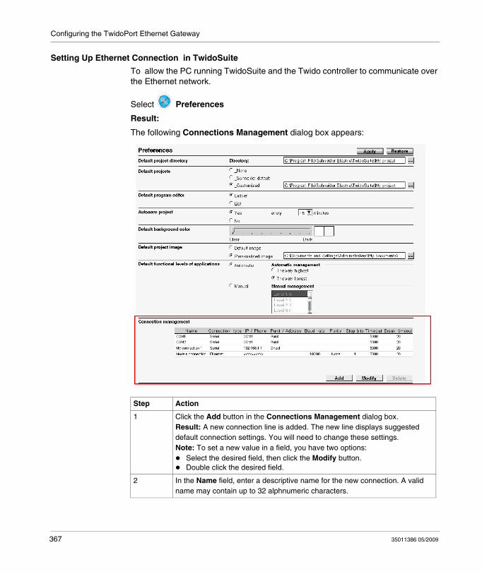
Configuring the TwidoPort Ethernet Gateway
Setting Up Ethernet Connection in TwidoSuite
To allow the PC running TwidoSuite and the Twido controller to communicate over the Ethernet network.
Select Preferences
Result:
The following Connections Management dialog box appears:
Step Action
1 Click the Add button in the Connections Management dialog box. Result: A new connection line is added. The new line displays suggested default connection settings. You will need to change these settings. Note: To set a new value in a field, you have two options:
Select the desired field, then click the Modify button.Double click the desired field.
2 In the Name field, enter a descriptive name for the new connection. A valid name may contain up to 32 alphnumeric characters.
367 35011386 05/2009
Configuring the TwidoPort Ethernet Gateway
3 In the Connection Type field, click to unfold the dropdown list that includes: Serial, Ethernet, and USB (if any).Select Ethernet as you are setting up a new Ethernet connection between your PC and an Ethernet-capable Twido controller.
4 In the IP / Phone field, enter a valid IP address which is the IP information of the Twido controller you wish to connect to.IP Address: Enter the static IP address that you have previously specified for your Twido controller.
5 The Punit / Address field can be filled in when IP / Phone has been selected.For an Ethernet connection, the default Punit/Address value is Direct. This default must be changed to 1 (or to whatever address you have previously used for the controller). Note: If you use an address different than 1, connection is not possible (whatever the address you configured for Port 1 (see page 364) of the Twido controller).For a Serial Type connection, default value is Punit. When any of those is selected, the next three fields (Baudrate, Parity and Stop Bits) are disabled.If you do not know the controller address, @ allows you to select it later, once the program has been transferred. (A window pops up before the first connection to let you choose the controller to which you transfer, with a 1-247 range, and 1 as the default address value.)
6 Use the default settings in Timeout and Break timeout fields, unless you have specific timeout needs. (For more details, please refer to .)
7 Click the OK button to save the new connection settings and close the Connections management dialog box.Result: All newly-added connections are appended in the Preferences → Connections Management table and in the Program → Debug → Connect → Select a connection table.
Step Action
35011386 05/2009 368
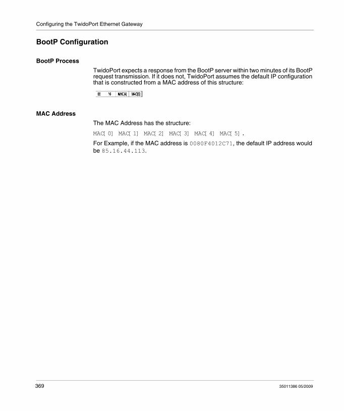
Configuring the TwidoPort Ethernet Gateway
BootP Configuration
BootP Process
TwidoPort expects a response from the BootP server within two minutes of its BootP request transmission. If it does not, TwidoPort assumes the default IP configuration that is constructed from a MAC address of this structure:
MAC Address
The MAC Address has the structure:
MAC[0] MAC[1] MAC[2] MAC[3] MAC[4] MAC[5].
For Example, if the MAC address is 0080F4012C71, the default IP address would be 85.16.44.113.
369 35011386 05/2009
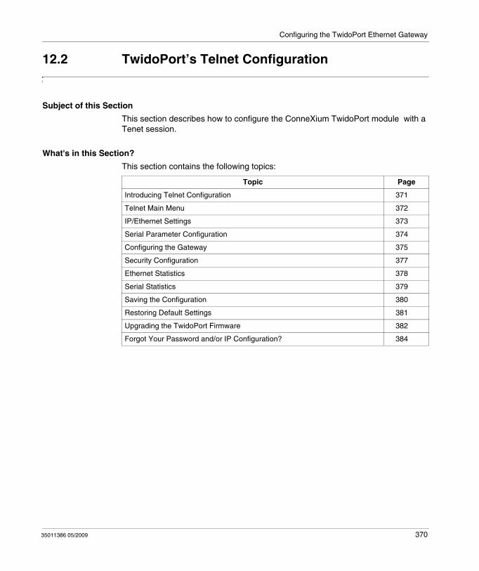
Configuring the TwidoPort Ethernet Gateway
12.2 TwidoPort’s Telnet Configuration
Subject of this Section
This section describes how to configure the ConneXium TwidoPort module with a Tenet session.
What's in this Section?
This section contains the following topics:
Topic Page
Introducing Telnet Configuration 371
Telnet Main Menu 372
IP/Ethernet Settings 373
Serial Parameter Configuration 374
Configuring the Gateway 375
Security Configuration 377
Ethernet Statistics 378
Serial Statistics 379
Saving the Configuration 380
Restoring Default Settings 381
Upgrading the TwidoPort Firmware 382
Forgot Your Password and/or IP Configuration? 384
35011386 05/2009 370
Configuring the TwidoPort Ethernet Gateway
Introducing Telnet Configuration
Overview of Telnet Configuration
Configure TwidoPort with a Telnet session (using a VT100-compatible Telnet client) for those cases in which a specific Twido configuration is not found or in which the BootP request is not answered after two minutes (resulting in the implementation of the default IP address).
Preparation to Telnet Configuration
NOTE: TwidoPort’s Telenet requirements
While configuring TwidoPort with Telnet, make sure:TwidoPort is supplied with power (from a Twido controller) through its serial connection.Telnet’s local echo is set to off.
To use Telnet, add TwidoPort's default IP address (or TwidoPort’s configured IP address) to the PC's routing table using the command:
Example:
If the IP address of the PC is 192.168.10.30 and the default IP address (or the configured IP address) of TwidoPort is 85.16.44.113, the complete command would be:
371 35011386 05/2009
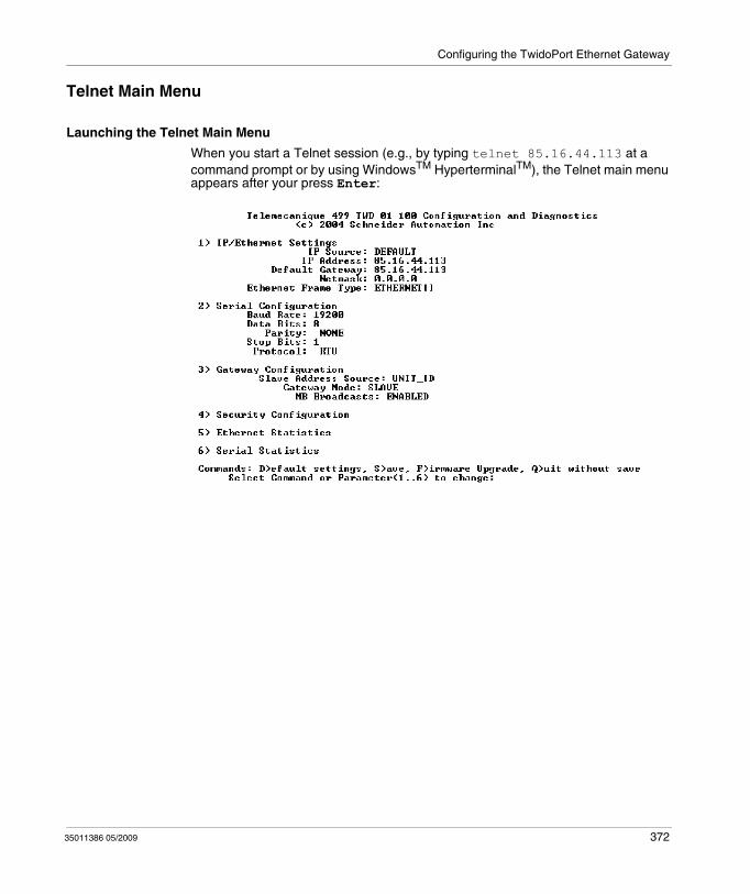
Configuring the TwidoPort Ethernet Gateway
Telnet Main Menu
Launching the Telnet Main Menu
When you start a Telnet session (e.g., by typing telnet 85.16.44.113 at a command prompt or by using WindowsTM HyperterminalTM), the Telnet main menu appears after your press Enter:
35011386 05/2009 372
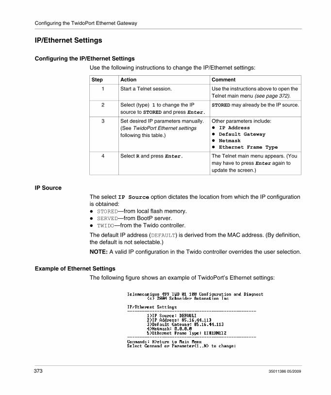
Configuring the TwidoPort Ethernet Gateway
IP/Ethernet Settings
Configuring the IP/Ethernet Settings
Use the following instructions to change the IP/Ethernet settings:
IP Source
The select IP Source option dictates the location from which the IP configuration is obtained:
STORED—from local flash memory.SERVED—from BootP server.TWIDO—from the Twido controller.
The default IP address (DEFAULT) is derived from the MAC address. (By definition, the default is not selectable.)
NOTE: A valid IP configuration in the Twido controller overrides the user selection.
Example of Ethernet Settings
The following figure shows an example of TwidoPort’s Ethernet settings:
Step Action Comment
1 Start a Telnet session. Use the instructions above to open the Telnet main menu (see page 372).
2 Select (type) 1 to change the IP source to STORED and press Enter.
STORED may already be the IP source.
3 Set desired IP parameters manually. (See TwidoPort Ethernet settings following this table.)
Other parameters include:IP AddressDefault GatewayNetmaskEthernet Frame Type
4 Select R and press Enter. The Telnet main menu appears. (You may have to press Enter again to update the screen.)
373 35011386 05/2009
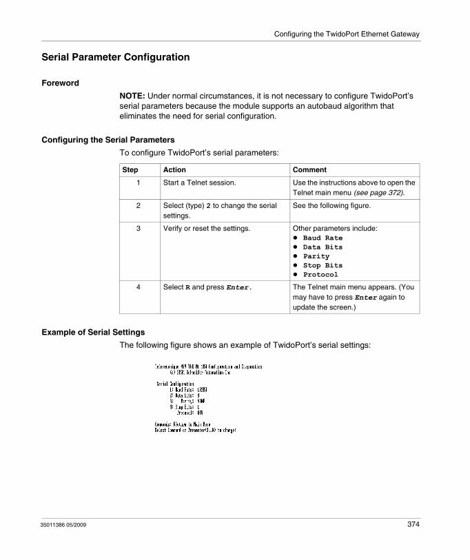
Configuring the TwidoPort Ethernet Gateway
Serial Parameter Configuration
Foreword
NOTE: Under normal circumstances, it is not necessary to configure TwidoPort’s serial parameters because the module supports an autobaud algorithm that eliminates the need for serial configuration.
Configuring the Serial Parameters
To configure TwidoPort’s serial parameters:
Example of Serial Settings
The following figure shows an example of TwidoPort’s serial settings:
Step Action Comment
1 Start a Telnet session. Use the instructions above to open the Telnet main menu (see page 372).
2 Select (type) 2 to change the serial settings.
See the following figure.
3 Verify or reset the settings. Other parameters include:Baud RateData BitsParityStop BitsProtocol
4 Select R and press Enter. The Telnet main menu appears. (You may have to press Enter again to update the screen.)
35011386 05/2009 374
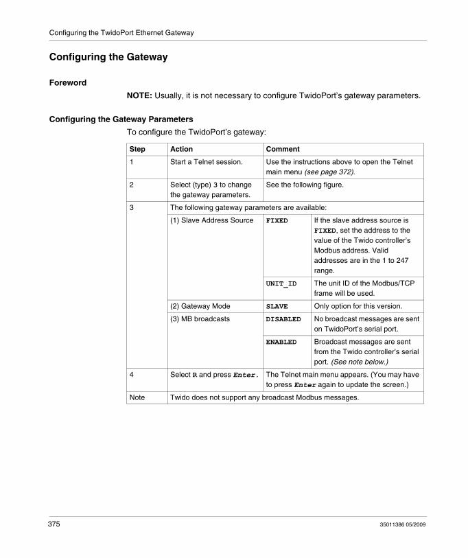
Configuring the TwidoPort Ethernet Gateway
Configuring the Gateway
Foreword
NOTE: Usually, it is not necessary to configure TwidoPort’s gateway parameters.
Configuring the Gateway Parameters
To configure the TwidoPort’s gateway:
Step Action Comment
1 Start a Telnet session. Use the instructions above to open the Telnet main menu (see page 372).
2 Select (type) 3 to change the gateway parameters.
See the following figure.
3 The following gateway parameters are available:
(1) Slave Address Source FIXED If the slave address source is FIXED, set the address to the value of the Twido controller’s Modbus address. Valid addresses are in the 1 to 247 range.
UNIT_ID The unit ID of the Modbus/TCP frame will be used.
(2) Gateway Mode SLAVE Only option for this version.
(3) MB broadcasts DISABLED No broadcast messages are sent on TwidoPort’s serial port.
ENABLED Broadcast messages are sent from the Twido controller’s serial port. (See note below.)
4 Select R and press Enter. The Telnet main menu appears. (You may have to press Enter again to update the screen.)
Note Twido does not support any broadcast Modbus messages.
375 35011386 05/2009
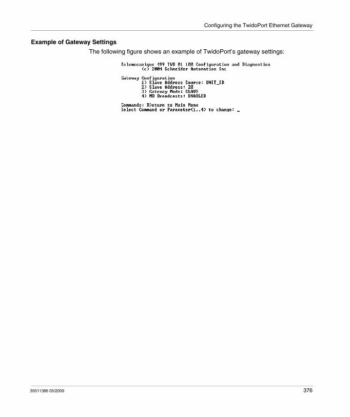
Configuring the TwidoPort Ethernet Gateway
Example of Gateway Settings
The following figure shows an example of TwidoPort’s gateway settings:
35011386 05/2009 376
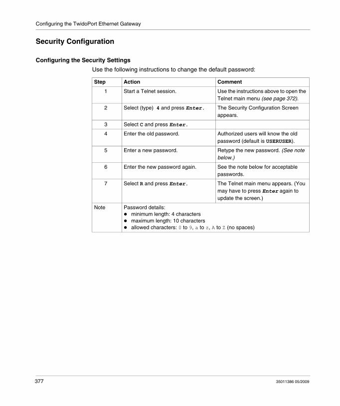
Configuring the TwidoPort Ethernet Gateway
Security Configuration
Configuring the Security Settings
Use the following instructions to change the default password:
Step Action Comment
1 Start a Telnet session. Use the instructions above to open the Telnet main menu (see page 372).
2 Select (type) 4 and press Enter. The Security Configuration Screen appears.
3 Select C and press Enter.
4 Enter the old password. Authorized users will know the old password (default is USERUSER).
5 Enter a new password. Retype the new password. (See note below.)
6 Enter the new password again. See the note below for acceptable passwords.
7 Select R and press Enter. The Telnet main menu appears. (You may have to press Enter again to update the screen.)
Note Password details:minimum length: 4 charactersmaximum length: 10 charactersallowed characters: 0 to 9, a to z, A to Z (no spaces)
377 35011386 05/2009
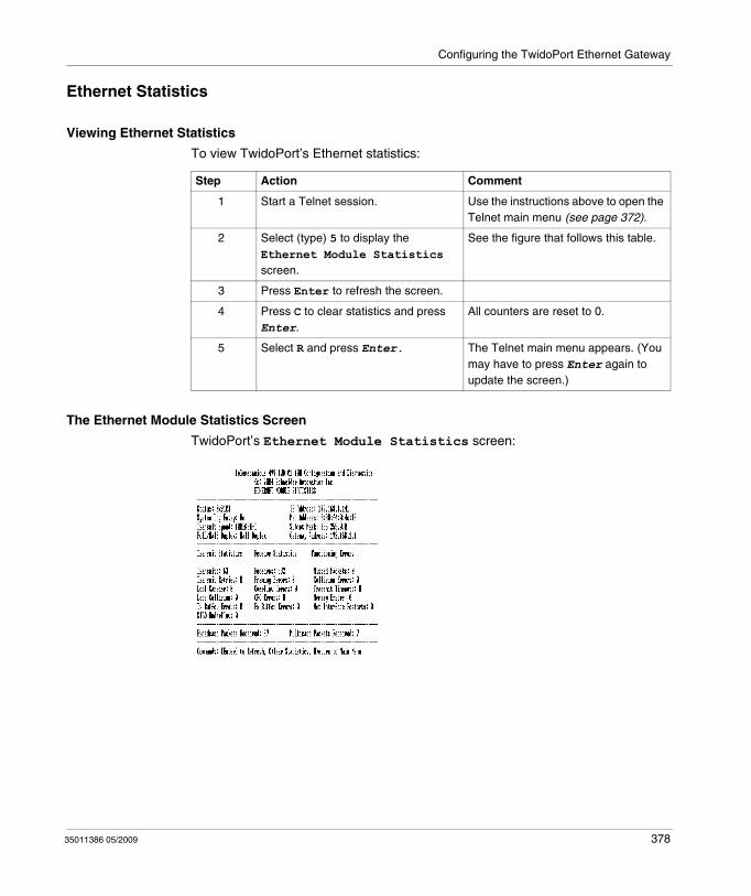
Configuring the TwidoPort Ethernet Gateway
Ethernet Statistics
Viewing Ethernet Statistics
To view TwidoPort’s Ethernet statistics:
The Ethernet Module Statistics Screen
TwidoPort’s Ethernet Module Statistics screen:
Step Action Comment
1 Start a Telnet session. Use the instructions above to open the Telnet main menu (see page 372).
2 Select (type) 5 to display the Ethernet Module Statistics screen.
See the figure that follows this table.
3 Press Enter to refresh the screen.
4 Press C to clear statistics and press Enter.
All counters are reset to 0.
5 Select R and press Enter. The Telnet main menu appears. (You may have to press Enter again to update the screen.)
35011386 05/2009 378
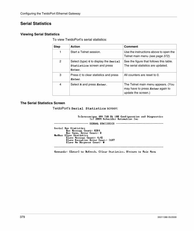
Configuring the TwidoPort Ethernet Gateway
Serial Statistics
Viewing Serial Statistics
To view TwidoPort’s serial statistics:
The Serial Statistics Screen
TwidoPort’s Serial Statistics screen:
Step Action Comment
1 Start a Telnet session. Use the instructions above to open the Telnet main menu (see page 372).
2 Select (type) 6 to display the Serial Statistics screen and press Enter.
See the figure that follows this table.The serial statistics are updated.
3 Press C to clear statistics and press Enter.
All counters are reset to 0.
4 Select R and press Enter. The Telnet main menu appears. (You may have to press Enter again to update the screen.)
379 35011386 05/2009
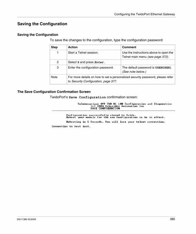
Configuring the TwidoPort Ethernet Gateway
Saving the Configuration
Saving the Configuration
To save the changes to the configuration, type the configuration password:
The Save Configuration Confirmation Screen
TwidoPort’s Save Configuration confirmation screen:
Step Action Comment
1 Start a Telnet session. Use the instructions above to open the Telnet main menu (see page 372).
2 Select S and press Enter.
3 Enter the configuration password. The default password is USERUSER).(See note below.)
Note For more details on how to set a personalized security password, please refer to Security Configuration, page 377.
35011386 05/2009 380
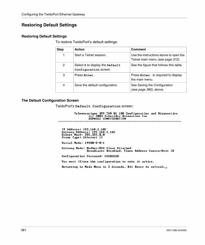
Configuring the TwidoPort Ethernet Gateway
Restoring Default Settings
Restoring Default Settings
To restore TwidoPort’s default settings:
The Default Configuration Screen
TwidoPort’s Default Configuration screen:
Step Action Comment
1 Start a Telnet session. Use the instructions above to open the Telnet main menu (see page 372).
2 Select D to display the Default Configuration screen.
See the figure that follows this table.
3 Press Enter. Press Enter. is required to display the main menu.
4 Save the default configuration. See Saving the Configuration (see page 380), above.
381 35011386 05/2009

Configuring the TwidoPort Ethernet Gateway
Upgrading the TwidoPort Firmware
Foreword
NOTE:
1. Obtain a newer version of the TwidoPort firmware before attempting to upgrade the firmware with these instructions.
2. Stop the process before upgrading the firmware.3. Modbus communication will not be available during the firmware upgrade
procedure.
Upgrading the Firmware
To upgrade the current TwidoPort’s firmware with the latest firmware release you have obtained, follow this procedure:
Step Action Comment
1 Start a Telnet session. Use the instructions above to open the Telnet main menu (see page 372).
2 Select (type) F to initiate the firmware upgrade.
Five seconds after selecting F (firmware upgrade), TwidoPort resets and the Telnet connection is lost.
3 At the command line, type: ftp and TwidoPort’s IP address.
For example: ftp 85.16.44.113
4 Enter: ftptwd At the login name prompt.
5 Enter: cd fw This takes the user to the fw directory.
6 Enter: put App.out .(See notes 1 and 2.)
A message indicates that the ftp was successful. (See note 3.)
Note 1 File names are case-sensitive.
Note 2 Make sure App.out is in the current working directory of the ftp client.
Note 3 A message indicates that TwidoPort will automatically reboot 5 seconds after a successful ftp.
35011386 05/2009 382
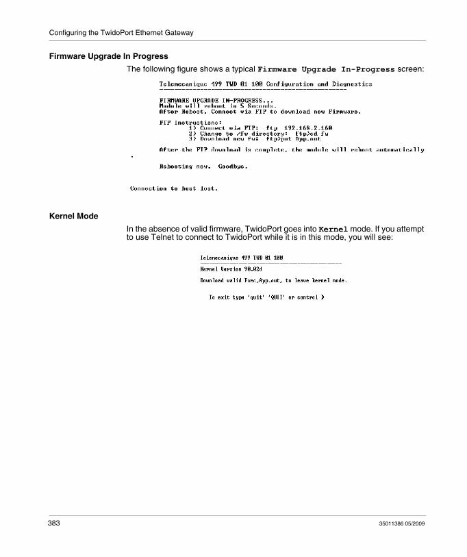
Configuring the TwidoPort Ethernet Gateway
Firmware Upgrade In Progress
The following figure shows a typical Firmware Upgrade In-Progress screen:
Kernel Mode
In the absence of valid firmware, TwidoPort goes into Kernel mode. If you attempt to use Telnet to connect to TwidoPort while it is in this mode, you will see:
383 35011386 05/2009
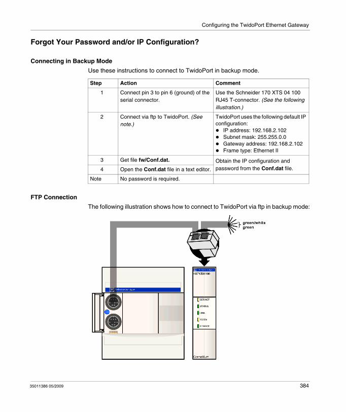
Configuring the TwidoPort Ethernet Gateway
Forgot Your Password and/or IP Configuration?
Connecting in Backup Mode
Use these instructions to connect to TwidoPort in backup mode.
FTP Connection
The following illustration shows how to connect to TwidoPort via ftp in backup mode:
Step Action Comment
1 Connect pin 3 to pin 6 (ground) of the serial connector.
Use the Schneider 170 XTS 04 100 RJ45 T-connector. (See the following illustration.)
2 Connect via ftp to TwidoPort. (See note.)
TwidoPort uses the following default IP configuration:
IP address: 192.168.2.102Subnet mask: 255.255.0.0Gateway address: 192.168.2.102Frame type: Ethernet II
3 Get file fw/Conf.dat. Obtain the IP configuration and password from the Conf.dat file.4 Open the Conf.dat file in a text editor.
Note No password is required.
35011386 05/2009 384
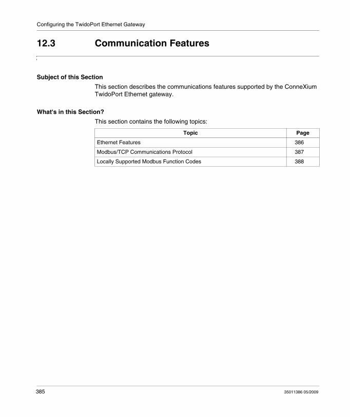
Configuring the TwidoPort Ethernet Gateway
12.3 Communication Features
Subject of this Section
This section describes the communications features supported by the ConneXium TwidoPort Ethernet gateway.
What's in this Section?
This section contains the following topics:
Topic Page
Ethernet Features 386
Modbus/TCP Communications Protocol 387
Locally Supported Modbus Function Codes 388
385 35011386 05/2009
Configuring the TwidoPort Ethernet Gateway
Ethernet Features
Introduction
The ConneXium TwidoPort adds Ethernet connectivity to the Schneider Electric Twido product line. It is the gateway between a single Twido Modbus/RTU (RS485) device and the physical layer of Modbus/TCP networks in slave mode. TwidoPort does not require a separate power supply because it gets power from the Twido controller through its serial port. This gateway module supports slave mode only.
Ethernet Features
TwidoPort supports the following Ethernet features:Auto-negotiationTwidoPort supports 10/100TX auto-negotiation. It communicates only in half-duplex mode.Auto-MDI/MDI-XTwidoPort supports auto-switching of transmit and receive wire pairs to establish communications with the end device (auto-MDI/MDI-X). TwidoPort, therefore, transparently interconnects infrastructure or end devices with either straight-through or crossover cables.
35011386 05/2009 386
Configuring the TwidoPort Ethernet Gateway
Modbus/TCP Communications Protocol
About Modbus
The Modbus protocol is a master/slave protocol that allows one master to request responses from slaves or to take action based on their requests. The master can address individual slaves or can initiate a broadcast message to all slaves. Slaves return a message (response) to queries that are addressed to them individually. Responses are not returned to broadcast queries from the master.
About Modbus/TCP Communications
TwidoPort supports up to 8 simultaneous Modbus/TCP connections. Attempting to use more than 8 connections results in a degradation of performance because TwidoPort closes the connection with the longest idle time to accept a new connection request.
Theory of Operations
Modbus/TCP clients can communicate with Twido through TwidoPort, a bridge between Twido devices (Modbus/RTU over RS485 serial link) and Modbus/TCP over Ethernet networks.
NOTE: When implementing TwidoPort on a network, the system design requirements must account for the inherent limited bandwidth of serial connections. Expect a peak performance of approximately 40 Modbus transactions per second. Requesting multiple registers in a single request is more efficient than placing a separate request for each register.
You cannot initiate read or write requests from the Twido controller through TwidoPort.
387 35011386 05/2009
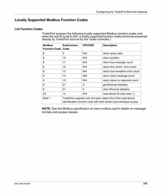
Configuring the TwidoPort Ethernet Gateway
Locally Supported Modbus Function Codes
List Function Codes
TwidoPort answers the following locally supported Modbus function codes only when the unit ID is set to 254. (Locally supported function codes are those answered directly by TwidoPort and not by the Twido controller.)
NOTE: See the Modbus specification at www.modbus.org for details on message formats and access classes.
Modbus Function Code
Subfunction Code
OPCODE Description
8 0 N/A return query data
8 10 N/A clear counters
8 11 N/A return bus message count
8 12 N/A return bus comm. error count
8 13 N/A return bus exception error count
8 14 N/A return slave message count
8 15 N/A return slave no response count
8 21 3 get Ethernet statistics
8 21 4 clear Ethernet statistics
43 14 N/A read device ID (see note 1.)
Note 1 TwidoPort supports only the basic object IDs of the read device identification function code with both stream and individual access.
35011386 05/2009 388

Configuring the TwidoPort Ethernet Gateway
389 35011386 05/2009
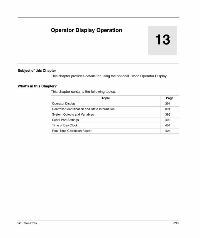
35011386 05/2009
13
Operator Display Operation
35011386 05/2009
Operator Display Operation
Subject of this Chapter
This chapter provides details for using the optional Twido Operator Display.
What's in this Chapter?
This chapter contains the following topics:
Topic Page
Operator Display 391
Controller Identification and State Information 394
System Objects and Variables 396
Serial Port Settings 403
Time of Day Clock 404
Real-Time Correction Factor 405
390
Operator Display Operation
Operator Display
Introduction
The Operator Display is a Twido option for displaying and controlling application data and some controller functions such as operating state and the Real-Time Clock (RTC). This option is available as a cartridge (TWDXCPODC) for the Compact controllers or as an expansion module (TWDXCPODM) for the Modular controllers.
The Operator Display has two operating modes:
Display Mode: only displays data.Edit mode: allows you to change data.
NOTE: The operator display is updated at a specific interval of the controller scan cycle. This can cause confusion in interpreting the display of dedicated outputs for %PLS or %PWM pulses. At the time these outputs are sampled, their value will always be zero, and this value will be displayed.
Displays and Functions
The Operator Display provides the following separate displays with the associated functions you can perform for each display.
Controller Identification and State Information: Operations DisplayDisplay firmware revision and the controller state. Change the controller state with the Run, Initial, and Stop commands.System Objects and Variables: Data DisplaySelect application data by the address: %I, %Q, and all other software objects on the base controller. Monitor and change the value of a selected software data object.Serial Port Settings: Communication DisplayDisplay and modify communication port settings.Time of Day Clock: Time/Date DisplayDisplay and configure the current date and time (if the RTC is installed).Real Time Correction: RTC FactorDisplay and modify the RTC Correction value for the optional RTC.
NOTE:
1. The TWDLC••40DRF series of compact controllers and the Twido Extreme TWDLEDCK1 PLC have an integrated RTC.
2. On all other controllers, time of day clock and real-time correction are only available if the Real-Time Clock (RTC) option cartridge (TWDXCPRTC) is installed.
391 35011386 05/2009
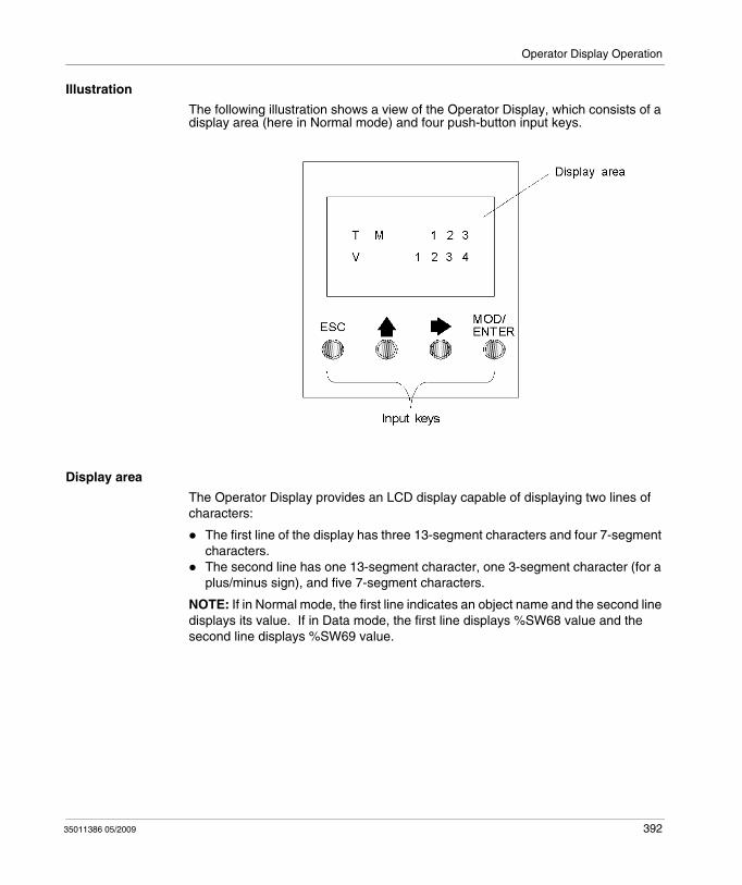
Operator Display Operation
Illustration
The following illustration shows a view of the Operator Display, which consists of a display area (here in Normal mode) and four push-button input keys.
Display area
The Operator Display provides an LCD display capable of displaying two lines of characters:
The first line of the display has three 13-segment characters and four 7-segment characters.The second line has one 13-segment character, one 3-segment character (for a plus/minus sign), and five 7-segment characters.
NOTE: If in Normal mode, the first line indicates an object name and the second line displays its value. If in Data mode, the first line displays %SW68 value and the second line displays %SW69 value.
35011386 05/2009 392
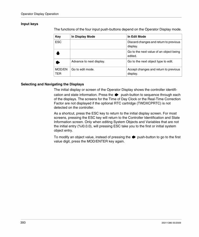
Operator Display Operation
Input keys
The functions of the four input push-buttons depend on the Operator Display mode.
Selecting and Navigating the Displays
The initial display or screen of the Operator Display shows the controller identifi-
cation and state information. Press the push-button to sequence through each of the displays. The screens for the Time of Day Clock or the Real-Time Correction Factor are not displayed if the optional RTC cartridge (TWDXCPRTC) is not detected on the controller.
As a shortcut, press the ESC key to return to the initial display screen. For most screens, pressing the ESC key will return to the Controller Identification and State Information screen. Only when editing System Objects and Variables that are not the initial entry (%I0.0.0), will pressing ESC take you to the first or initial system object entry.
To modify an object value, instead of pressing the push-button to go to the first value digit, press the MOD/ENTER key again.
Key In Display Mode In Edit Mode
ESC Discard changes and return to previous display.
Go to the next value of an object being edited.
Advance to next display. Go to the next object type to edit.
MOD/ENTER
Go to edit mode. Accept changes and return to previous display.
393 35011386 05/2009
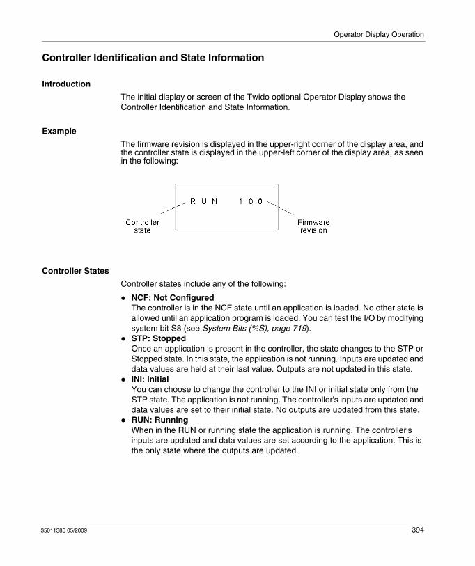
Operator Display Operation
Controller Identification and State Information
Introduction
The initial display or screen of the Twido optional Operator Display shows the Controller Identification and State Information.
Example
The firmware revision is displayed in the upper-right corner of the display area, and the controller state is displayed in the upper-left corner of the display area, as seen in the following:
Controller States
Controller states include any of the following:
NCF: Not ConfiguredThe controller is in the NCF state until an application is loaded. No other state is allowed until an application program is loaded. You can test the I/O by modifying system bit S8 (see System Bits (%S), page 719). STP: StoppedOnce an application is present in the controller, the state changes to the STP or Stopped state. In this state, the application is not running. Inputs are updated and data values are held at their last value. Outputs are not updated in this state.INI: InitialYou can choose to change the controller to the INI or initial state only from the STP state. The application is not running. The controller's inputs are updated and data values are set to their initial state. No outputs are updated from this state.RUN: RunningWhen in the RUN or running state the application is running. The controller's inputs are updated and data values are set according to the application. This is the only state where the outputs are updated.
35011386 05/2009 394
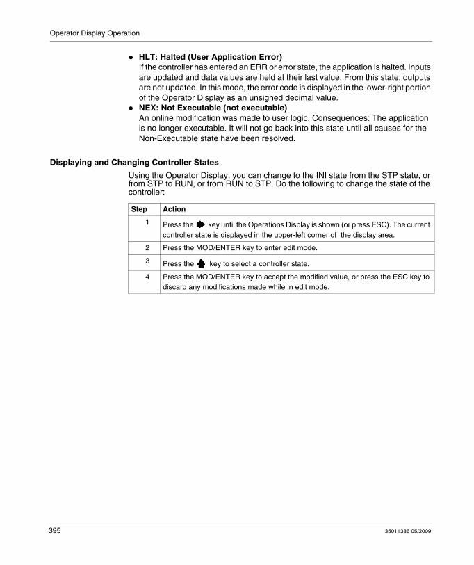
Operator Display Operation
HLT: Halted (User Application Error)If the controller has entered an ERR or error state, the application is halted. Inputs are updated and data values are held at their last value. From this state, outputs are not updated. In this mode, the error code is displayed in the lower-right portion of the Operator Display as an unsigned decimal value.NEX: Not Executable (not executable)An online modification was made to user logic. Consequences: The application is no longer executable. It will not go back into this state until all causes for the Non-Executable state have been resolved.
Displaying and Changing Controller States
Using the Operator Display, you can change to the INI state from the STP state, or from STP to RUN, or from RUN to STP. Do the following to change the state of the controller:
Step Action
1 Press the key until the Operations Display is shown (or press ESC). The current controller state is displayed in the upper-left corner of the display area.
2 Press the MOD/ENTER key to enter edit mode.
3 Press the key to select a controller state.
4 Press the MOD/ENTER key to accept the modified value, or press the ESC key to discard any modifications made while in edit mode.
395 35011386 05/2009
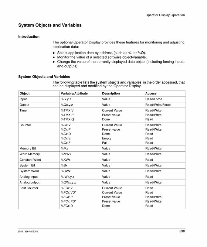
Operator Display Operation
System Objects and Variables
Introduction
The optional Operator Display provides these features for monitoring and adjusting application data:
Select application data by address (such as %I or %Q).Monitor the value of a selected software object/variable.Change the value of the currently displayed data object (including forcing inputs and outputs).
System Objects and Variables
The following table lists the system objects and variables, in the order accessed, that can be displayed and modified by the Operator Display.
Object Variable/Attribute Description Access
Input %Ix.y.z Value Read/Force
Output %Qx.y.z Value Read/Write/Force
Timer %TMX.V%TMX.P%TMX.Q
Current ValuePreset valueDone
Read/WriteRead/WriteRead
Counter %Cx.V%Cx.P%Cx.D%Cx.E%Cx.F
Current ValuePreset valueDoneEmptyFull
Read/WriteRead/WriteReadReadRead
Memory Bit %Mx Value Read/Write
Word Memory %MWx Value Read/Write
Constant Word %KWx Value Read
System Bit %Sx Value Read/Write
System Word %SWx Value Read/Write
Analog Input %IWx.y.z Value Read
Analog output %QWx.y.z Value Read/Write
Fast Counter %FCx.V%FCx.VD*%FCx.P%FCx.PD*%FCx.D
Current ValueCurrent ValuePreset valuePreset valueDone
ReadReadRead/WriteRead/WriteRead
35011386 05/2009 396
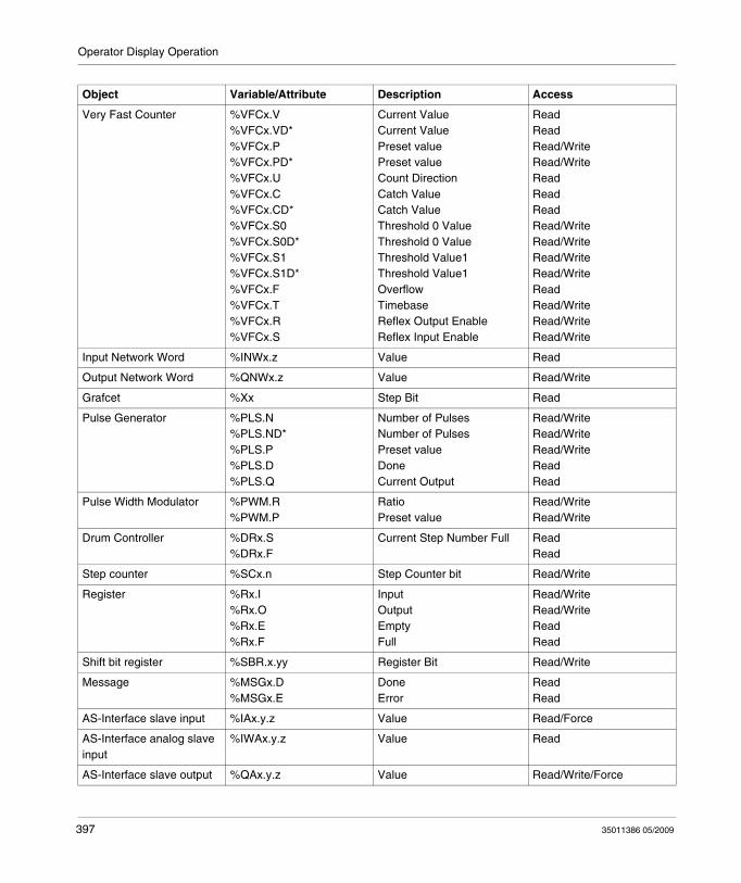
Operator Display Operation
Very Fast Counter %VFCx.V%VFCx.VD*%VFCx.P%VFCx.PD*%VFCx.U%VFCx.C%VFCx.CD*%VFCx.S0%VFCx.S0D*%VFCx.S1%VFCx.S1D*%VFCx.F%VFCx.T%VFCx.R%VFCx.S
Current ValueCurrent ValuePreset valuePreset valueCount DirectionCatch ValueCatch ValueThreshold 0 ValueThreshold 0 ValueThreshold Value1Threshold Value1OverflowTimebaseReflex Output EnableReflex Input Enable
ReadReadRead/WriteRead/WriteReadReadReadRead/WriteRead/WriteRead/WriteRead/WriteReadRead/WriteRead/WriteRead/Write
Input Network Word %INWx.z Value Read
Output Network Word %QNWx.z Value Read/Write
Grafcet %Xx Step Bit Read
Pulse Generator %PLS.N%PLS.ND*%PLS.P%PLS.D%PLS.Q
Number of PulsesNumber of PulsesPreset valueDoneCurrent Output
Read/WriteRead/WriteRead/WriteReadRead
Pulse Width Modulator %PWM.R%PWM.P
RatioPreset value
Read/WriteRead/Write
Drum Controller %DRx.S%DRx.F
Current Step Number Full ReadRead
Step counter %SCx.n Step Counter bit Read/Write
Register %Rx.I%Rx.O%Rx.E%Rx.F
InputOutputEmptyFull
Read/WriteRead/WriteReadRead
Shift bit register %SBR.x.yy Register Bit Read/Write
Message %MSGx.D%MSGx.E
DoneError
ReadRead
AS-Interface slave input %IAx.y.z Value Read/Force
AS-Interface analog slave input
%IWAx.y.z Value Read
AS-Interface slave output %QAx.y.z Value Read/Write/Force
Object Variable/Attribute Description Access
397 35011386 05/2009
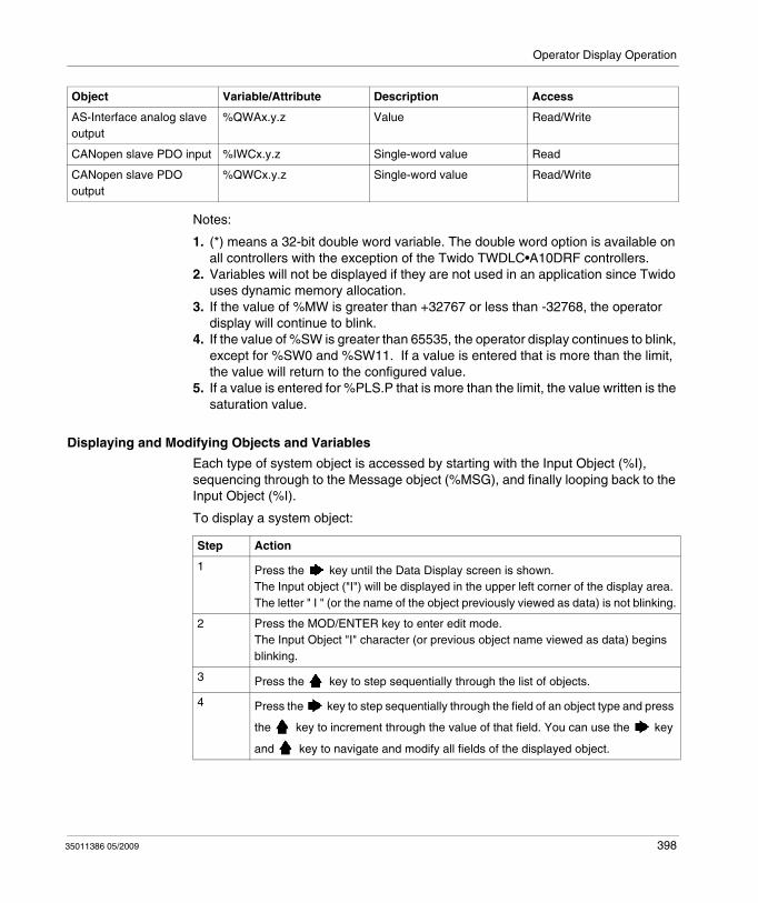
Operator Display Operation
Notes:
1. (*) means a 32-bit double word variable. The double word option is available on all controllers with the exception of the Twido TWDLC•A10DRF controllers.
2. Variables will not be displayed if they are not used in an application since Twido uses dynamic memory allocation.
3. If the value of %MW is greater than +32767 or less than -32768, the operator display will continue to blink.
4. If the value of %SW is greater than 65535, the operator display continues to blink, except for %SW0 and %SW11. If a value is entered that is more than the limit, the value will return to the configured value.
5. If a value is entered for %PLS.P that is more than the limit, the value written is the saturation value.
Displaying and Modifying Objects and Variables
Each type of system object is accessed by starting with the Input Object (%I), sequencing through to the Message object (%MSG), and finally looping back to the Input Object (%I).
To display a system object:
AS-Interface analog slave output
%QWAx.y.z Value Read/Write
CANopen slave PDO input %IWCx.y.z Single-word value Read
CANopen slave PDO output
%QWCx.y.z Single-word value Read/Write
Object Variable/Attribute Description Access
Step Action
1 Press the key until the Data Display screen is shown.The Input object ("I") will be displayed in the upper left corner of the display area. The letter " I " (or the name of the object previously viewed as data) is not blinking.
2 Press the MOD/ENTER key to enter edit mode.The Input Object "I" character (or previous object name viewed as data) begins blinking.
3 Press the key to step sequentially through the list of objects.
4 Press the key to step sequentially through the field of an object type and press
the key to increment through the value of that field. You can use the key
and key to navigate and modify all fields of the displayed object.
35011386 05/2009 398
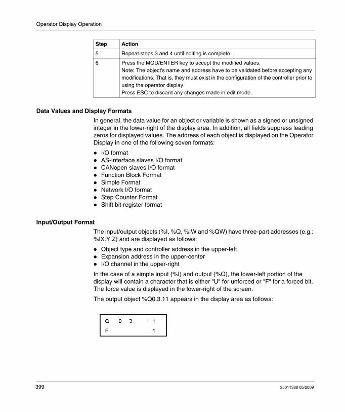
Operator Display Operation
Data Values and Display Formats
In general, the data value for an object or variable is shown as a signed or unsigned integer in the lower-right of the display area. In addition, all fields suppress leading zeros for displayed values. The address of each object is displayed on the Operator Display in one of the following seven formats:
I/O formatAS-Interface slaves I/O formatCANopen slaves I/O formatFunction Block FormatSimple FormatNetwork I/O formatStep Counter FormatShift bit register format
Input/Output Format
The input/output objects (%I, %Q, %IW and %QW) have three-part addresses (e.g.: %IX.Y.Z) and are displayed as follows:
Object type and controller address in the upper-leftExpansion address in the upper-centerI/O channel in the upper-right
In the case of a simple input (%I) and output (%Q), the lower-left portion of the display will contain a character that is either "U" for unforced or "F" for a forced bit. The force value is displayed in the lower-right of the screen.
The output object %Q0.3.11 appears in the display area as follows:
5 Repeat steps 3 and 4 until editing is complete.
6 Press the MOD/ENTER key to accept the modified values.Note: The object's name and address have to be validated before accepting any modifications. That is, they must exist in the configuration of the controller prior to using the operator display.Press ESC to discard any changes made in edit mode.
Step Action
399 35011386 05/2009
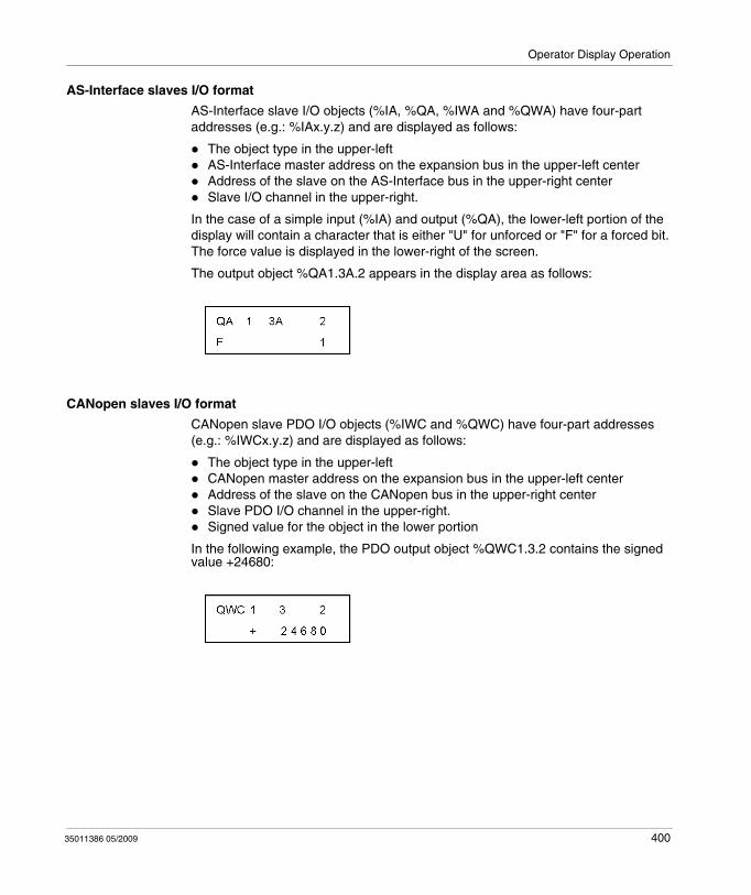
Operator Display Operation
AS-Interface slaves I/O format
AS-Interface slave I/O objects (%IA, %QA, %IWA and %QWA) have four-part addresses (e.g.: %IAx.y.z) and are displayed as follows:
The object type in the upper-leftAS-Interface master address on the expansion bus in the upper-left centerAddress of the slave on the AS-Interface bus in the upper-right centerSlave I/O channel in the upper-right.
In the case of a simple input (%IA) and output (%QA), the lower-left portion of the display will contain a character that is either "U" for unforced or "F" for a forced bit. The force value is displayed in the lower-right of the screen.
The output object %QA1.3A.2 appears in the display area as follows:
CANopen slaves I/O format
CANopen slave PDO I/O objects (%IWC and %QWC) have four-part addresses (e.g.: %IWCx.y.z) and are displayed as follows:
The object type in the upper-leftCANopen master address on the expansion bus in the upper-left centerAddress of the slave on the CANopen bus in the upper-right centerSlave PDO I/O channel in the upper-right.Signed value for the object in the lower portion
In the following example, the PDO output object %QWC1.3.2 contains the signed value +24680:
35011386 05/2009 400
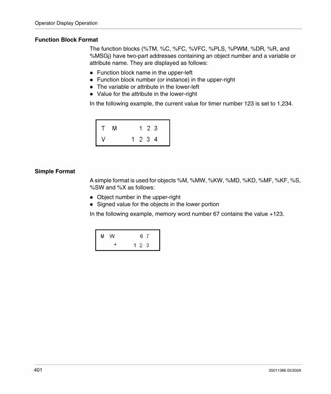
Operator Display Operation
Function Block Format
The function blocks (%TM, %C, %FC, %VFC, %PLS, %PWM, %DR, %R, and %MSGj) have two-part addresses containing an object number and a variable or attribute name. They are displayed as follows:
Function block name in the upper-leftFunction block number (or instance) in the upper-rightThe variable or attribute in the lower-leftValue for the attribute in the lower-right
In the following example, the current value for timer number 123 is set to 1,234.
Simple Format
A simple format is used for objects %M, %MW, %KW, %MD, %KD, %MF, %KF, %S, %SW and %X as follows:
Object number in the upper-rightSigned value for the objects in the lower portion
In the following example, memory word number 67 contains the value +123.
401 35011386 05/2009
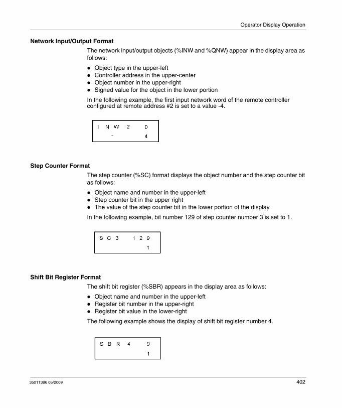
Operator Display Operation
Network Input/Output Format
The network input/output objects (%INW and %QNW) appear in the display area as follows:
Object type in the upper-leftController address in the upper-centerObject number in the upper-rightSigned value for the object in the lower portion
In the following example, the first input network word of the remote controller configured at remote address #2 is set to a value -4.
Step Counter Format
The step counter (%SC) format displays the object number and the step counter bit as follows:
Object name and number in the upper-leftStep counter bit in the upper rightThe value of the step counter bit in the lower portion of the display
In the following example, bit number 129 of step counter number 3 is set to 1.
Shift Bit Register Format
The shift bit register (%SBR) appears in the display area as follows:
Object name and number in the upper-leftRegister bit number in the upper-rightRegister bit value in the lower-right
The following example shows the display of shift bit register number 4.
35011386 05/2009 402
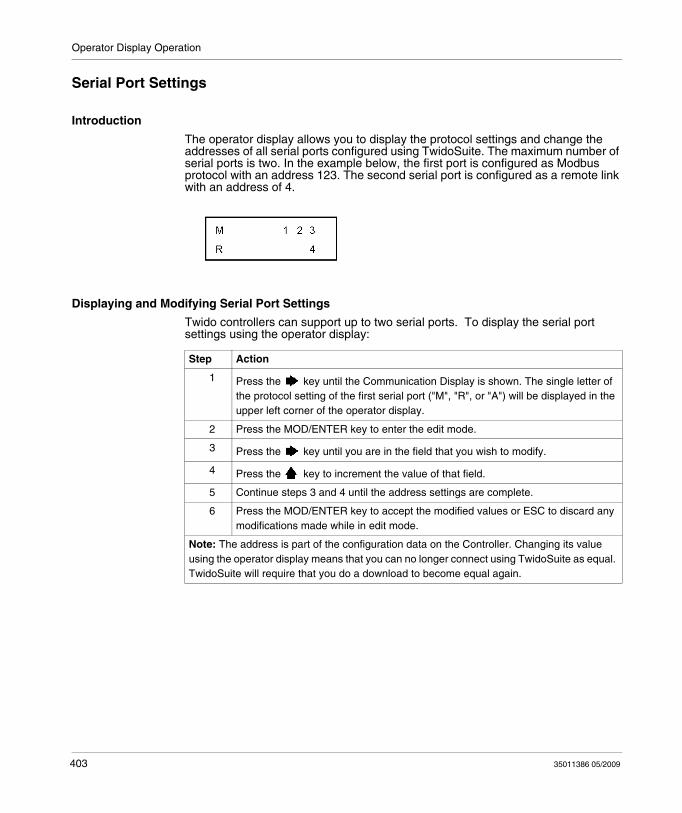
Operator Display Operation
Serial Port Settings
Introduction
The operator display allows you to display the protocol settings and change the addresses of all serial ports configured using TwidoSuite. The maximum number of serial ports is two. In the example below, the first port is configured as Modbus protocol with an address 123. The second serial port is configured as a remote link with an address of 4.
Displaying and Modifying Serial Port Settings
Twido controllers can support up to two serial ports. To display the serial port settings using the operator display:
Step Action
1 Press the key until the Communication Display is shown. The single letter of the protocol setting of the first serial port ("M", "R", or "A") will be displayed in the upper left corner of the operator display.
2 Press the MOD/ENTER key to enter the edit mode.
3 Press the key until you are in the field that you wish to modify.
4 Press the key to increment the value of that field.
5 Continue steps 3 and 4 until the address settings are complete.
6 Press the MOD/ENTER key to accept the modified values or ESC to discard any modifications made while in edit mode.
Note: The address is part of the configuration data on the Controller. Changing its value using the operator display means that you can no longer connect using TwidoSuite as equal. TwidoSuite will require that you do a download to become equal again.
403 35011386 05/2009
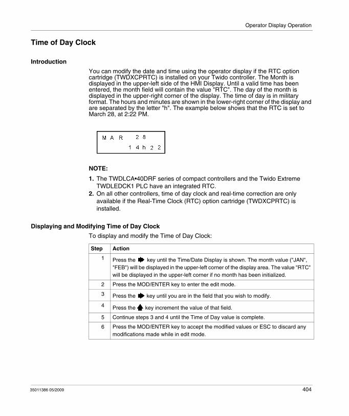
Operator Display Operation
Time of Day Clock
Introduction
You can modify the date and time using the operator display if the RTC option cartridge (TWDXCPRTC) is installed on your Twido controller. The Month is displayed in the upper-left side of the HMI Display. Until a valid time has been entered, the month field will contain the value "RTC". The day of the month is displayed in the upper-right corner of the display. The time of day is in military format. The hours and minutes are shown in the lower-right corner of the display and are separated by the letter "h". The example below shows that the RTC is set to March 28, at 2:22 PM.
NOTE:
1. The TWDLCA•40DRF series of compact controllers and the Twido Extreme TWDLEDCK1 PLC have an integrated RTC.
2. On all other controllers, time of day clock and real-time correction are only available if the Real-Time Clock (RTC) option cartridge (TWDXCPRTC) is installed.
Displaying and Modifying Time of Day Clock
To display and modify the Time of Day Clock:
Step Action
1 Press the key until the Time/Date Display is shown. The month value ("JAN", "FEB") will be displayed in the upper-left corner of the display area. The value "RTC" will be displayed in the upper-left corner if no month has been initialized.
2 Press the MOD/ENTER key to enter the edit mode.
3 Press the key until you are in the field that you wish to modify.
4 Press the key increment the value of that field.
5 Continue steps 3 and 4 until the Time of Day value is complete.
6 Press the MOD/ENTER key to accept the modified values or ESC to discard any modifications made while in edit mode.
35011386 05/2009 404
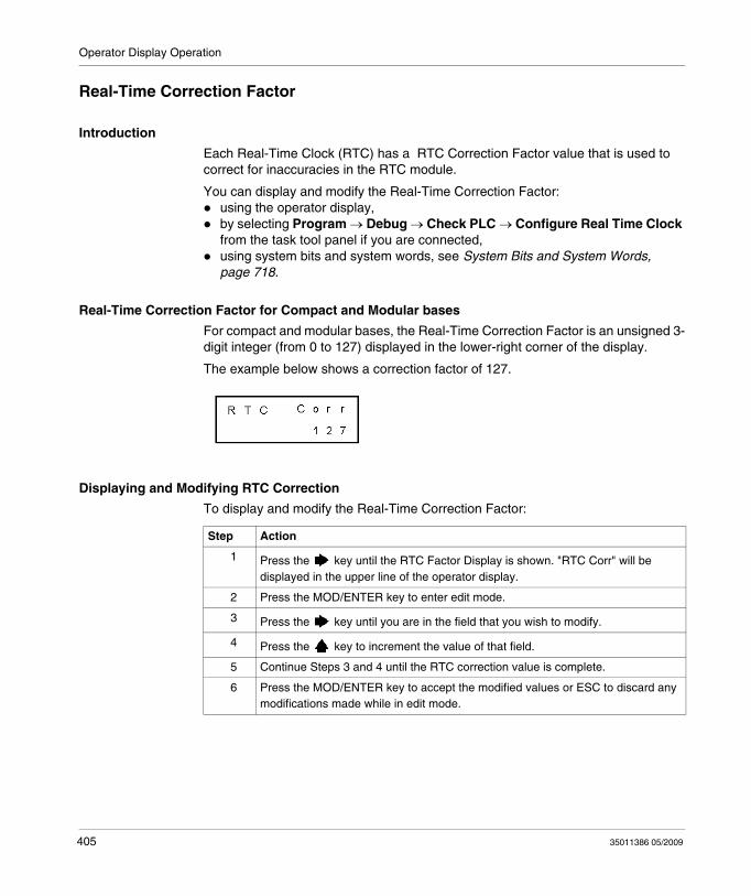
Operator Display Operation
Real-Time Correction Factor
Introduction
Each Real-Time Clock (RTC) has a RTC Correction Factor value that is used to correct for inaccuracies in the RTC module.
You can display and modify the Real-Time Correction Factor:using the operator display,by selecting Program → Debug → Check PLC → Configure Real Time Clock from the task tool panel if you are connected,using system bits and system words, see System Bits and System Words, page 718.
Real-Time Correction Factor for Compact and Modular bases
For compact and modular bases, the Real-Time Correction Factor is an unsigned 3-digit integer (from 0 to 127) displayed in the lower-right corner of the display.
The example below shows a correction factor of 127.
Displaying and Modifying RTC Correction
To display and modify the Real-Time Correction Factor:
Step Action
1 Press the key until the RTC Factor Display is shown. "RTC Corr" will be displayed in the upper line of the operator display.
2 Press the MOD/ENTER key to enter edit mode.
3 Press the key until you are in the field that you wish to modify.
4 Press the key to increment the value of that field.
5 Continue Steps 3 and 4 until the RTC correction value is complete.
6 Press the MOD/ENTER key to accept the modified values or ESC to discard any modifications made while in edit mode.
405 35011386 05/2009
Operator Display Operation
Real-Time Correction Factor for Twido Extreme Bases
For Twido Extreme TWDLEDCK1 bases, the Real-Time Correction Factor needs to be calculated as follows:
The Real-Time Correction Factor for Twido Extreme is a 6 bit value:
Step Action
1 Set the Real-Time Clock Value.
2 After a few weeks, determine the deviation of the Real-Time Clock on your PLC.
3 Calculate the factor necessary for a Real-Time Correction on a weekly basis.
4 Set the Real-Time Correction Factor with this value.Result: the Real-Time Correction Factor will be added to (or subtracted from) the Real-Time Clock value of your PLC every week.
Bits Description Possible values
0
The correction factor in seconds
0 to 63
1
2
3
4
5
6 Sign of the correction factor 0: subtraction1: addition
35011386 05/2009 406

Operator Display Operation
407 35011386 05/2009
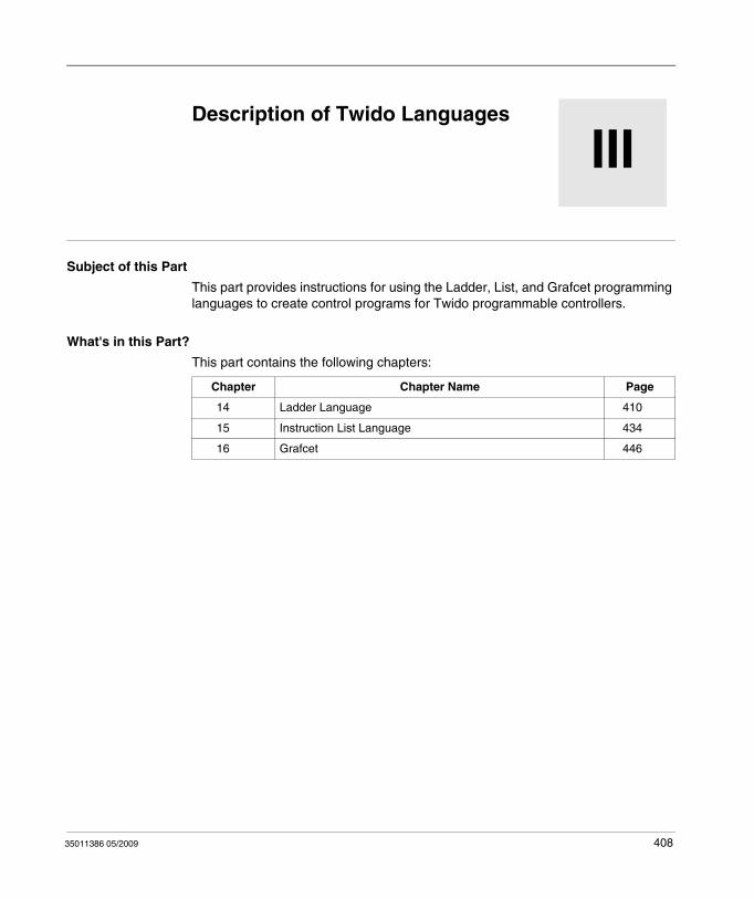
35011386 05/2009
III
Twido Languages
35011386 05/2009
Description of Twido Languages
Subject of this Part
This part provides instructions for using the Ladder, List, and Grafcet programming languages to create control programs for Twido programmable controllers.
What's in this Part?
This part contains the following chapters:
Chapter Chapter Name Page
14 Ladder Language 410
15 Instruction List Language 434
16 Grafcet 446
408

Twido Languages
409 35011386 05/2009
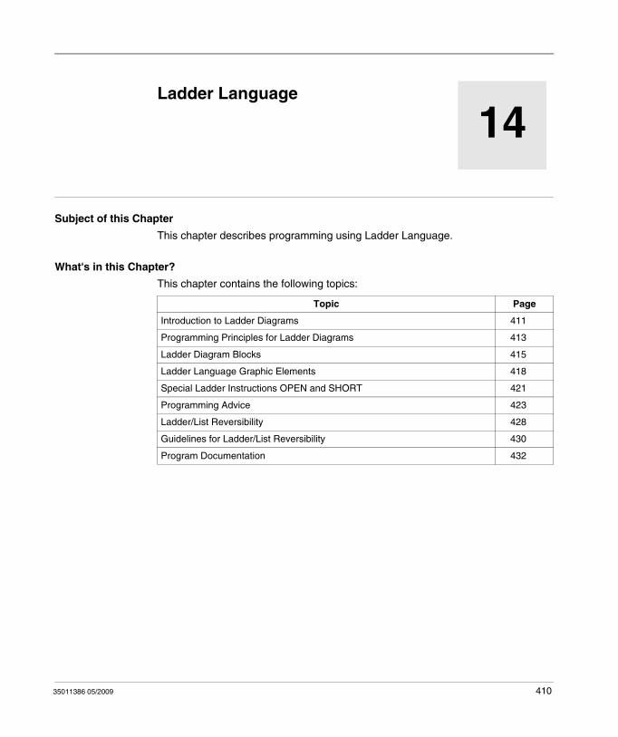
35011386 05/2009
14
Ladder Language
35011386 05/2009
Ladder Language
Subject of this Chapter
This chapter describes programming using Ladder Language.
What's in this Chapter?
This chapter contains the following topics:
Topic Page
Introduction to Ladder Diagrams 411
Programming Principles for Ladder Diagrams 413
Ladder Diagram Blocks 415
Ladder Language Graphic Elements 418
Special Ladder Instructions OPEN and SHORT 421
Programming Advice 423
Ladder/List Reversibility 428
Guidelines for Ladder/List Reversibility 430
Program Documentation 432
410
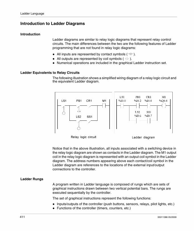
Ladder Language
Introduction to Ladder Diagrams
Introduction
Ladder diagrams are similar to relay logic diagrams that represent relay control circuits. The main differences between the two are the following features of Ladder programming that are not found in relay logic diagrams:
All inputs are represented by contact symbols ( ).All outputs are represented by coil symbols ( ).Numerical operations are included in the graphical Ladder instruction set.
Ladder Equivalents to Relay Circuits
The following illustration shows a simplified wiring diagram of a relay logic circuit and the equivalent Ladder diagram.
Notice that in the above illustration, all inputs associated with a switching device in the relay logic diagram are shown as contacts in the Ladder diagram. The M1 output coil in the relay logic diagram is represented with an output coil symbol in the Ladder diagram. The address numbers appearing above each contact/coil symbol in the Ladder diagram are references to the locations of the external input/output connections to the controller.
Ladder Rungs
A program written in Ladder language is composed of rungs which are sets of graphical instructions drawn between two vertical potential bars. The rungs are executed sequentially by the controller.
The set of graphical instructions represent the following functions:
Inputs/outputs of the controller (push buttons, sensors, relays, pilot lights, etc.)Functions of the controller (timers, counters, etc.)
411 35011386 05/2009
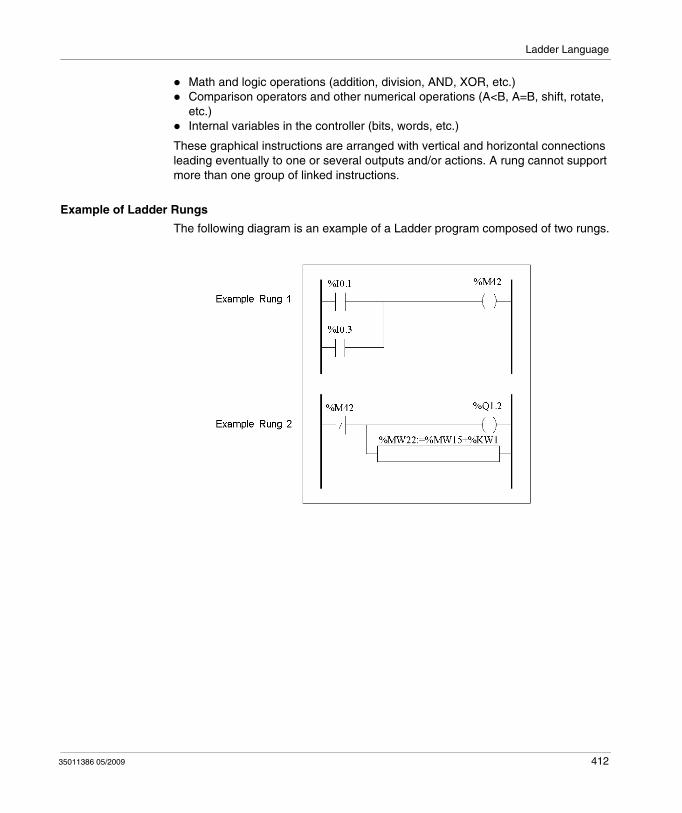
Ladder Language
Math and logic operations (addition, division, AND, XOR, etc.)Comparison operators and other numerical operations (A<B, A=B, shift, rotate, etc.)Internal variables in the controller (bits, words, etc.)
These graphical instructions are arranged with vertical and horizontal connections leading eventually to one or several outputs and/or actions. A rung cannot support more than one group of linked instructions.
Example of Ladder Rungs
The following diagram is an example of a Ladder program composed of two rungs.
35011386 05/2009 412
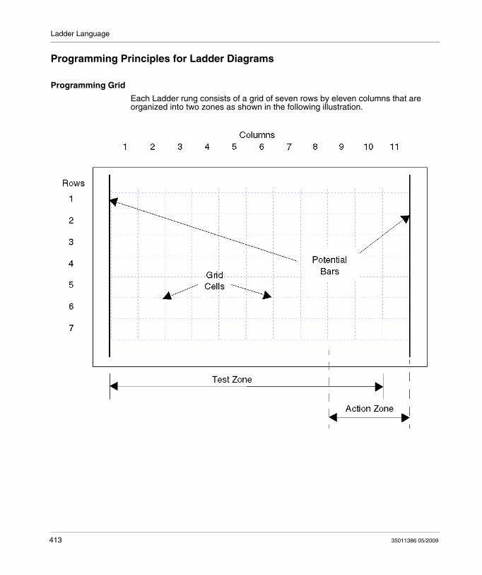
Ladder Language
Programming Principles for Ladder Diagrams
Programming Grid
Each Ladder rung consists of a grid of seven rows by eleven columns that are organized into two zones as shown in the following illustration.
413 35011386 05/2009
Ladder Language
Grid Zones
The Ladder diagram programming grid is divided into two zones:
Test ZoneContains the conditions that are tested in order to perform actions. Consists of columns 1 - 10, and contains contacts, function blocks, and comparison blocks.Action ZoneContains the output or operation that will be performed according to the results of the tests of the conditions in the Test Zone. Consists of columns 8 - 11, and contains coils and operation blocks.
Entering Instructions in the Grid
A Ladder rung provides a seven by eleven programming grid that starts in the first cell in the upper left-hand corner of the grid. Programming consists of entering instructions into the cells of the grid. Test instructions, comparisons, and functions are entered in cells in the test zone and are left-justified. The test logic provides continuity to the action zone where coils, numerical operations, and program flow control instructions are entered and are right-justified.
The rung is solved or executed (tests made and outputs assigned) within the grid from top to bottom and from left to right.
Sections/Subroutines
Each section/subroutine consists of:
A section header with with section number (automatically assigned by the program), section/subroutine label, a user-defined section/subroutine title and four lines of user comments. See .A sequence of rungs below the section/subroutine header.
Rung Headers
In addition to the rung, a rung header appears directly above the rung. Use the rung header to document the logical purpose of the rung. The rung header can contain the following information:
Rung numberLabels (%Li)Rung titleRung comments
For more details about using the rung header to document your programs, see Program Documentation, page 432.
35011386 05/2009 414
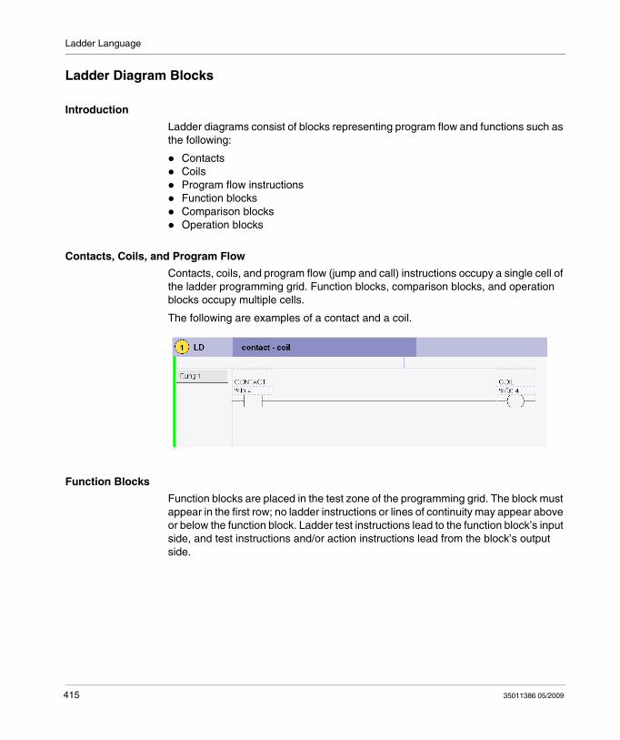
Ladder Language
Ladder Diagram Blocks
Introduction
Ladder diagrams consist of blocks representing program flow and functions such as the following:
ContactsCoilsProgram flow instructionsFunction blocksComparison blocksOperation blocks
Contacts, Coils, and Program Flow
Contacts, coils, and program flow (jump and call) instructions occupy a single cell of the ladder programming grid. Function blocks, comparison blocks, and operation blocks occupy multiple cells.
The following are examples of a contact and a coil.
Function Blocks
Function blocks are placed in the test zone of the programming grid. The block must appear in the first row; no ladder instructions or lines of continuity may appear above or below the function block. Ladder test instructions lead to the function block’s input side, and test instructions and/or action instructions lead from the block’s output side.
415 35011386 05/2009
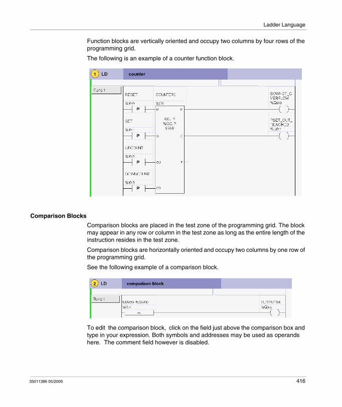
Ladder Language
Function blocks are vertically oriented and occupy two columns by four rows of the programming grid.
The following is an example of a counter function block.
Comparison Blocks
Comparison blocks are placed in the test zone of the programming grid. The block may appear in any row or column in the test zone as long as the entire length of the instruction resides in the test zone.
Comparison blocks are horizontally oriented and occupy two columns by one row of the programming grid.
See the following example of a comparison block.
To edit the comparison block, click on the field just above the comparison box and type in your expression. Both symbols and addresses may be used as operands here. The comment field however is disabled.
35011386 05/2009 416
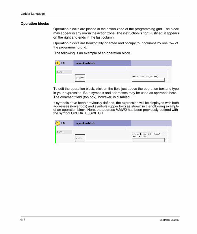
Ladder Language
Operation blocks
Operation blocks are placed in the action zone of the programming grid. The block may appear in any row in the action zone. The instruction is right-justified; it appears on the right and ends in the last column.
Operation blocks are horizontally oriented and occupy four columns by one row of the programming grid.
The following is an example of an operation block.
To edit the operation block, click on the field just above the operation box and type in your expression. Both symbols and addresses may be used as operands here. The comment field (top box), however, is disabled.
If symbols have been previously defined, the expression will be displayed with both addresses (lower box) and symbols (upper box) as shown in the following example of an operation block. Here, the address %MW2 has been previously defined with the symbol OPERATE_SWITCH.
417 35011386 05/2009
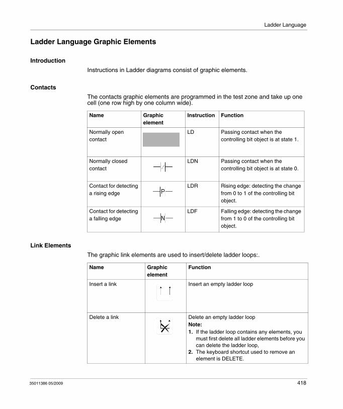
Ladder Language
Ladder Language Graphic Elements
Introduction
Instructions in Ladder diagrams consist of graphic elements.
Contacts
The contacts graphic elements are programmed in the test zone and take up one cell (one row high by one column wide).
Link Elements
The graphic link elements are used to insert/delete ladder loops:.
Name Graphic element
Instruction Function
Normally open contact
LD Passing contact when the controlling bit object is at state 1.
Normally closed contact
LDN Passing contact when the controlling bit object is at state 0.
Contact for detecting a rising edge
LDR Rising edge: detecting the change from 0 to 1 of the controlling bit object.
Contact for detecting a falling edge
LDF Falling edge: detecting the change from 1 to 0 of the controlling bit object.
Name Graphic element
Function
Insert a link Insert an empty ladder loop
Delete a link Delete an empty ladder loopNote:1. If the ladder loop contains any elements, you
must first delete all ladder elements before you can delete the ladder loop,
2. The keyboard shortcut used to remove an element is DELETE.
35011386 05/2009 418
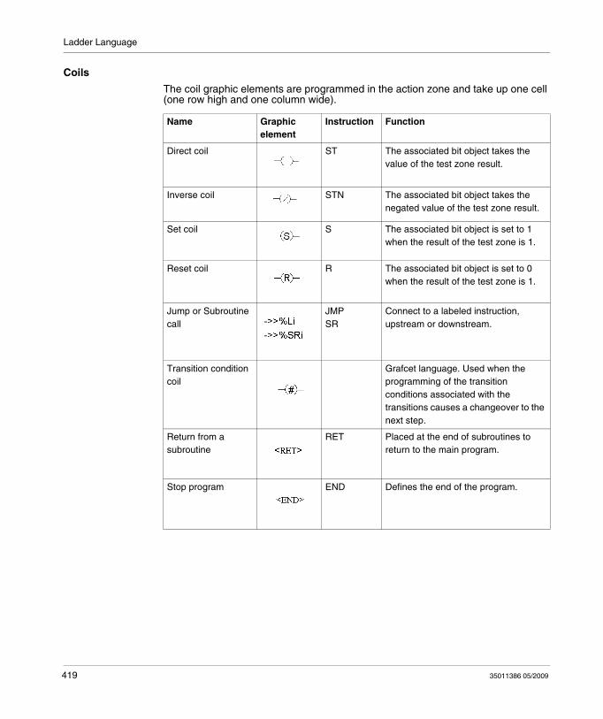
Ladder Language
Coils
The coil graphic elements are programmed in the action zone and take up one cell (one row high and one column wide).
Name Graphic element
Instruction Function
Direct coil ST The associated bit object takes the value of the test zone result.
Inverse coil STN The associated bit object takes the negated value of the test zone result.
Set coil S The associated bit object is set to 1 when the result of the test zone is 1.
Reset coil R The associated bit object is set to 0 when the result of the test zone is 1.
Jump or Subroutine call
JMPSR
Connect to a labeled instruction, upstream or downstream.
Transition condition coil
Grafcet language. Used when the programming of the transition conditions associated with the transitions causes a changeover to the next step.
Return from a subroutine
RET Placed at the end of subroutines to return to the main program.
Stop program END Defines the end of the program.
419 35011386 05/2009
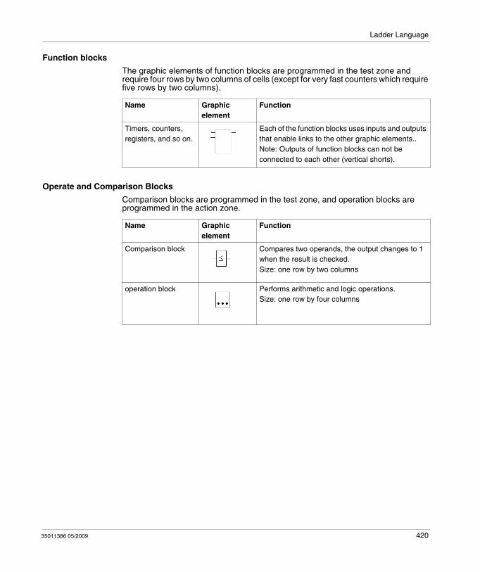
Ladder Language
Function blocks
The graphic elements of function blocks are programmed in the test zone and require four rows by two columns of cells (except for very fast counters which require five rows by two columns).
Operate and Comparison Blocks
Comparison blocks are programmed in the test zone, and operation blocks are programmed in the action zone.
Name Graphic element
Function
Timers, counters, registers, and so on.
Each of the function blocks uses inputs and outputs that enable links to the other graphic elements..Note: Outputs of function blocks can not be connected to each other (vertical shorts).
Name Graphic element
Function
Comparison block Compares two operands, the output changes to 1 when the result is checked.Size: one row by two columns
operation block Performs arithmetic and logic operations.Size: one row by four columns
35011386 05/2009 420
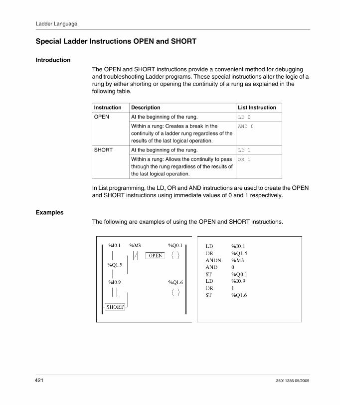
Ladder Language
Special Ladder Instructions OPEN and SHORT
Introduction
The OPEN and SHORT instructions provide a convenient method for debugging and troubleshooting Ladder programs. These special instructions alter the logic of a rung by either shorting or opening the continuity of a rung as explained in the following table.
In List programming, the LD, OR and AND instructions are used to create the OPEN and SHORT instructions using immediate values of 0 and 1 respectively.
Examples
The following are examples of using the OPEN and SHORT instructions.
Instruction Description List Instruction
OPEN At the beginning of the rung. LD 0
Within a rung: Creates a break in the continuity of a ladder rung regardless of the results of the last logical operation.
AND 0
SHORT At the beginning of the rung. LD 1
Within a rung: Allows the continuity to pass through the rung regardless of the results of the last logical operation.
OR 1
421 35011386 05/2009
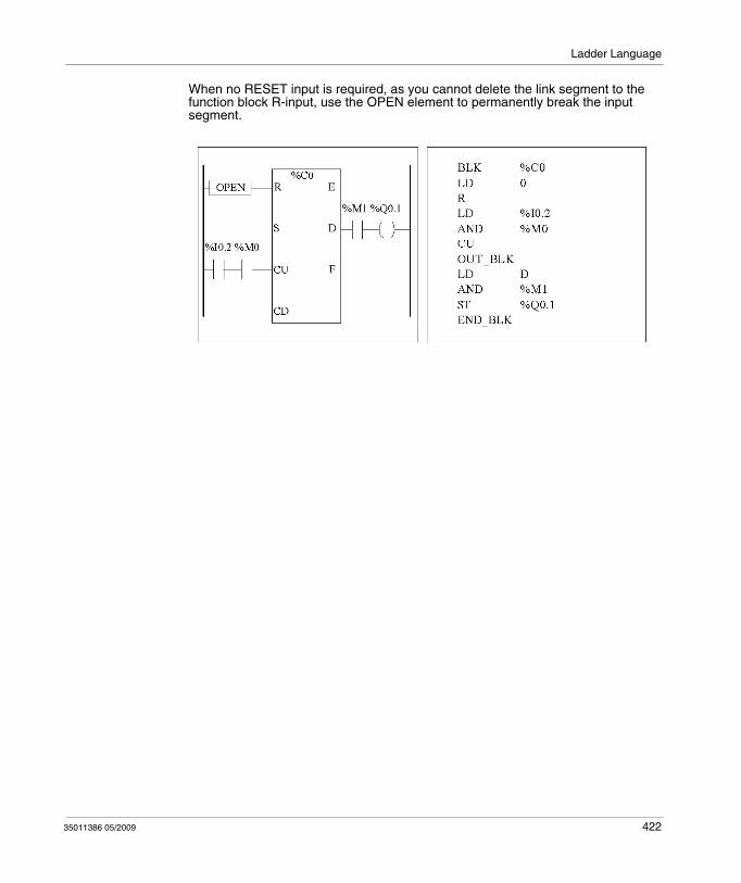
Ladder Language
When no RESET input is required, as you cannot delete the link segment to the function block R-input, use the OPEN element to permanently break the input segment.
35011386 05/2009 422
Ladder Language
Programming Advice
Handling Program Jumps
Use program jumps with care to avoid long loops that can increase scan time. Avoid jumps to instructions that are located upstream. (An upstream instruction line appears before a jump in a program. A downstream instruction line appears after a jump in a program.).
Programming of Outputs
Output bits, like internal bits, should only be modified once in the program. In the case of output bits, only the last value scanned is taken into account when the outputs are updated.
Using Directly-Wired Emergency Stop Sensors
Sensors used directly for emergency stops must not be processed by the controller. They must be connected directly to the corresponding outputs.
Handling Power Returns
Make power returns conditional on a manual operation. An automatic restart of the installation could cause unexpected operation of equipment (use system bits %S0, %S1 and %S9).
Time and Schedule Block Management
The state of system bit %S51, which indicates any RTC faults, should be checked.
Syntax and Error Checking
When a program is entered, TwidoSuite checks the syntax of the instructions, the operands, and their association.
423 35011386 05/2009
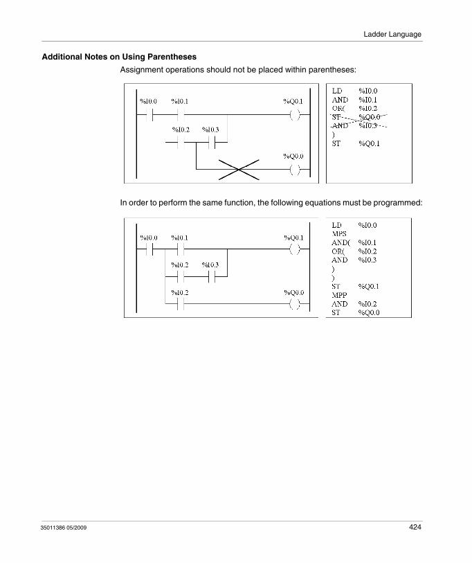
Ladder Language
Additional Notes on Using Parentheses
Assignment operations should not be placed within parentheses:
In order to perform the same function, the following equations must be programmed:
35011386 05/2009 424
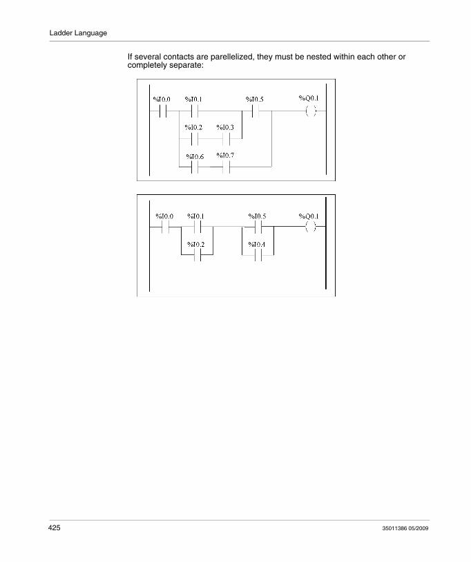
Ladder Language
If several contacts are parellelized, they must be nested within each other or completely separate:
425 35011386 05/2009
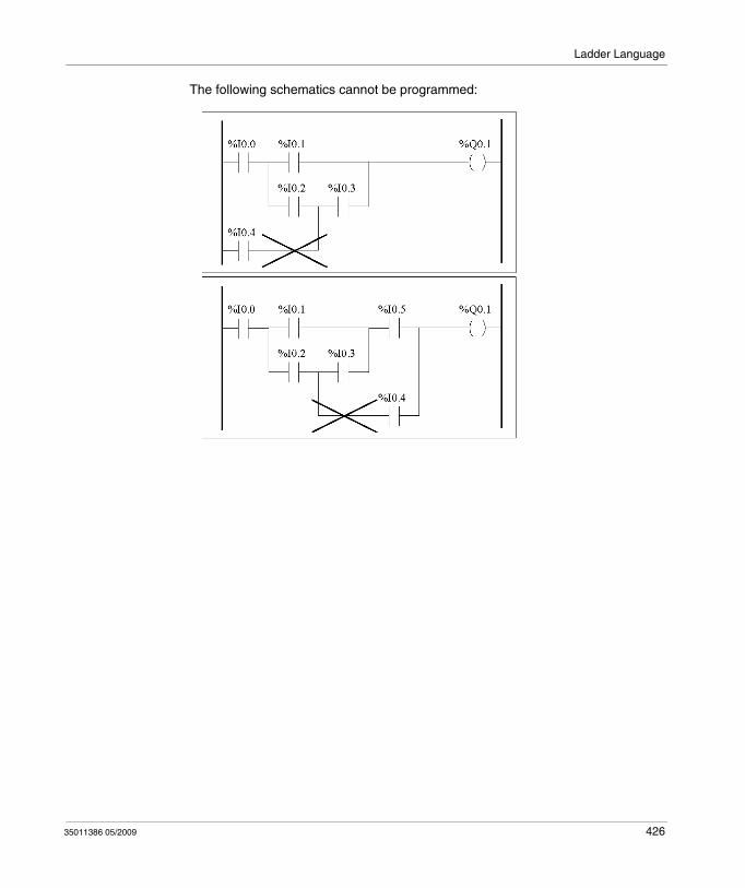
Ladder Language
The following schematics cannot be programmed:
35011386 05/2009 426
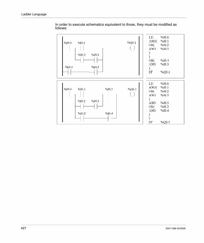
Ladder Language
In order to execute schematics equivalent to those, they must be modified as follows:
427 35011386 05/2009
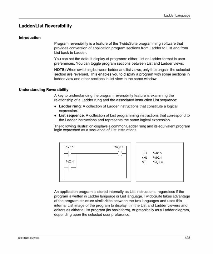
Ladder Language
Ladder/List Reversibility
Introduction
Program reversibility is a feature of the TwidoSuite programming software that provides conversion of application program sections from Ladder to List and from List back to Ladder.
You can set the default display of programs: either List or Ladder format in user preferences. You can toggle program sections between List and Ladder views.
NOTE: When switching between ladder and list views, only the rungs in the selected section are reversed. This enables you to display a program with some sections in ladder view and other sections in list view in the same window.
Understanding Reversibility
A key to understanding the program reversibility feature is examining the relationship of a Ladder rung and the associated instruction List sequence:
Ladder rung: A collection of Ladder instructions that constitute a logical expression.List sequence: A collection of List programming instructions that correspond to the Ladder instructions and represents the same logical expression.
The following illustration displays a common Ladder rung and its equivalent program logic expressed as a sequence of List instructions.
An application program is stored internally as List instructions, regardless if the program is written in Ladder language or List language. TwidoSuite takes advantage of the program structure similarities between the two languages and uses this internal List image of the program to display it in the List and Ladder viewers and editors as either a List program (its basic form), or graphically as a Ladder diagram, depending upon the selected user preference.
35011386 05/2009 428

Ladder Language
Ensuring Reversibility
Programs created in Ladder can always be reversed to List. However, some List logic may not reverse to Ladder. To ensure reversibility from List to Ladder, it is important to follow the set of List programming guidelines in Guidelines for Ladder/List Reversibility, page 430.
429 35011386 05/2009
Ladder Language
Guidelines for Ladder/List Reversibility
Instructions Required for Reversibility
The structure of a reversible function block in List language requires the use of the following instructions:
BLK marks the block start, and defines the beginning of the rung and the start of the input portion to the block.OUT_BLK marks the beginning of the output portion of the block.END_BLK marks the end of the block and the rung.
The use of the reversible function block instructions are not mandatory for a properly functioning List program. For some instructions it is possible to program in List which is not reversible. For a description of non-reversible List programming of standard function blocks, see Standard function blocks programming principles, page 481.
Non-Equivalent Instructions to Avoid
Avoid the use of certain List instructions, or certain combinations of instructions and operands, which have no equivalents in Ladder diagrams. For example, the N instruction (inverses the value in the Boolean accumulator) has no equivalent Ladder instruction.
The following table identifies all List programming instructions that will not reverse to Ladder.
Unconditional Rungs
Programming unconditional rungs also requires following List programming guidelines to ensure List-to-Ladder reversibility. Unconditional rungs do not have tests or conditions. The outputs or action instructions are always executed.
List Instruction Operand Description
JMPCN %Li Jump Conditional Not
N none Negation (Not)
ENDCN none End Conditional Not
35011386 05/2009 430
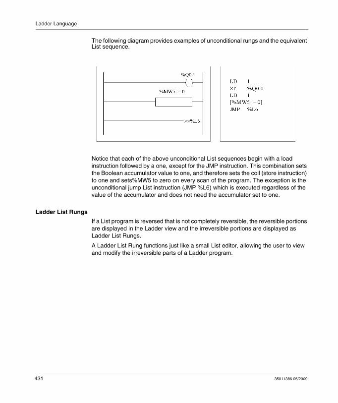
Ladder Language
The following diagram provides examples of unconditional rungs and the equivalent List sequence.
Notice that each of the above unconditional List sequences begin with a load instruction followed by a one, except for the JMP instruction. This combination sets the Boolean accumulator value to one, and therefore sets the coil (store instruction) to one and sets%MW5 to zero on every scan of the program. The exception is the unconditional jump List instruction (JMP %L6) which is executed regardless of the value of the accumulator and does not need the accumulator set to one.
Ladder List Rungs
If a List program is reversed that is not completely reversible, the reversible portions are displayed in the Ladder view and the irreversible portions are displayed as Ladder List Rungs.
A Ladder List Rung functions just like a small List editor, allowing the user to view and modify the irreversible parts of a Ladder program.
431 35011386 05/2009

Ladder Language
Program Documentation
Documenting Your Program
You can document your program by entering comments using the List and Ladder editors:
Use the List Editor to document your program with List Line Comments. These comments may appear on the same line as programming instructions, or they may appear on lines of their own.Use the Ladder Editor to document your program using rung headers. These are found directly above the rung.
The TwidoSuite programming software uses these comments for reversibility. When reversing a program from List to Ladder, TwidoSuite uses some of the List comments to construct a rung header. For this, the comments inserted between List sequences are used for rung headers.
Example of List Line Comments
The following is an example of a List program with List Line Comments.
35011386 05/2009 432
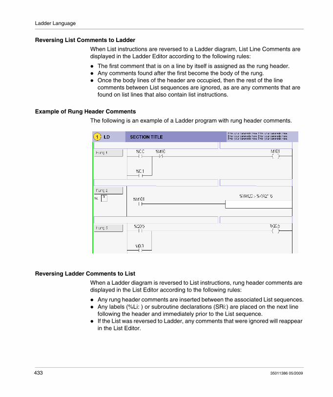
Ladder Language
Reversing List Comments to Ladder
When List instructions are reversed to a Ladder diagram, List Line Comments are displayed in the Ladder Editor according to the following rules:
The first comment that is on a line by itself is assigned as the rung header.Any comments found after the first become the body of the rung.Once the body lines of the header are occupied, then the rest of the line comments between List sequences are ignored, as are any comments that are found on list lines that also contain list instructions.
Example of Rung Header Comments
The following is an example of a Ladder program with rung header comments.
Reversing Ladder Comments to List
When a Ladder diagram is reversed to List instructions, rung header comments are displayed in the List Editor according to the following rules:
Any rung header comments are inserted between the associated List sequences.Any labels (%Li: ) or subroutine declarations (SRi:) are placed on the next line following the header and immediately prior to the List sequence.If the List was reversed to Ladder, any comments that were ignored will reappear in the List Editor.
433 35011386 05/2009
35011386 05/2009
15
Instruction List Language
35011386 05/2009
Instruction List Language
Subject of this Chapter
This chapter describes programming using Instruction List Language.
What's in this Chapter?
This chapter contains the following topics:
Topic Page
Overview of List Programs 435
Operation of List Instructions 437
List Language Instructions 438
Using Parentheses 441
Stack Instructions (MPS, MRD, MPP) 444
434
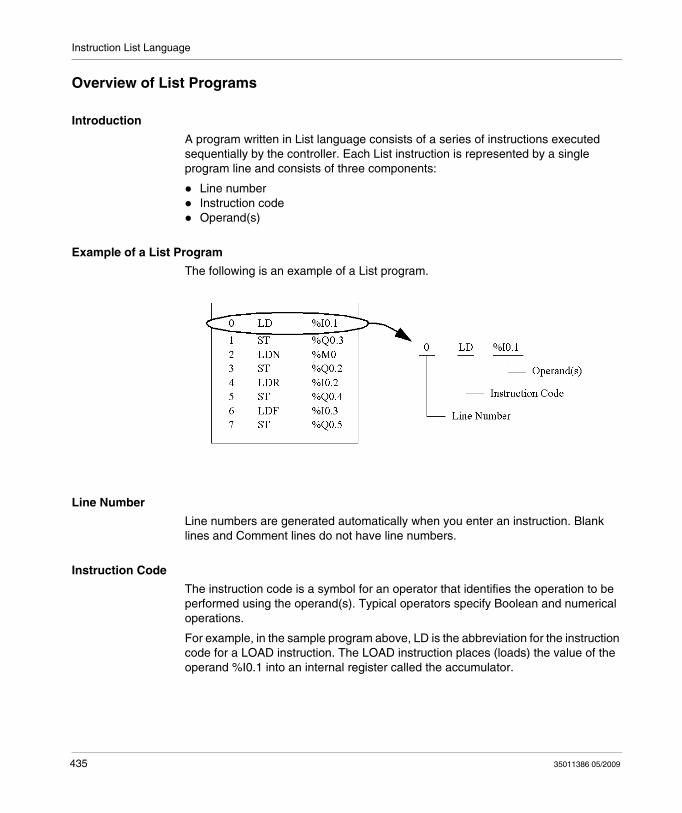
Instruction List Language
Overview of List Programs
Introduction
A program written in List language consists of a series of instructions executed sequentially by the controller. Each List instruction is represented by a single program line and consists of three components:
Line numberInstruction codeOperand(s)
Example of a List Program
The following is an example of a List program.
Line Number
Line numbers are generated automatically when you enter an instruction. Blank lines and Comment lines do not have line numbers.
Instruction Code
The instruction code is a symbol for an operator that identifies the operation to be performed using the operand(s). Typical operators specify Boolean and numerical operations.
For example, in the sample program above, LD is the abbreviation for the instruction code for a LOAD instruction. The LOAD instruction places (loads) the value of the operand %I0.1 into an internal register called the accumulator.
435 35011386 05/2009
Instruction List Language
There are basically two types of instructions:
Test instructionsThese setup or test for the necessary conditions to perform an action. For example, LOAD (LD) and AND.Action instructionsThese perform actions as a result of setup conditions. For example, assignment instructions such as STORE (ST) and RESET (R).
Operand
An operand is a number, address, or symbol representing a value that a program can manipulate in an instruction. For example, in the sample program above, the operand %I0.1 is an address assigned the value of an input to the controller. An instruction can have from zero to three operands depending on the type of instruction code.
Operands can represent the following:
Controller inputs and outputs such as sensors, push buttons, and relays.Predefined system functions such as timers and counters. Arithmetic, logical, comparison, and numerical operations.Controller internal variables such as bits and words.
35011386 05/2009 436
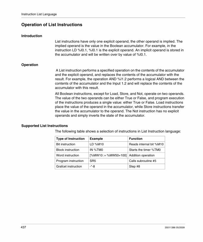
Instruction List Language
Operation of List Instructions
Introduction
List instructions have only one explicit operand, the other operand is implied. The implied operand is the value in the Boolean accumulator. For example, in the instruction LD %I0.1, %I0.1 is the explicit operand. An implicit operand is stored in the accumulator and will be written over by value of %I0.1.
Operation
A List instruction performs a specified operation on the contents of the accumulator and the explicit operand, and replaces the contents of the accumulator with the result. For example, the operation AND %I1.2 performs a logical AND between the contents of the accumulator and the Input 1.2 and will replace the contents of the accumulator with this result.
All Boolean instructions, except for Load, Store, and Not, operate on two operands. The value of the two operands can be either True or False, and program execution of the instructions produces a single value: either True or False. Load instructions place the value of the operand in the accumulator, while Store instructions transfer the value in the accumulator to the operand. The Not instruction has no explicit operands and simply inverts the state of the accumulator.
Supported List Instructions
The following table shows a selection of instructions in List Instruction language:
Type of Instruction Example Function
Bit instruction LD %M10 Reads internal bit %M10
Block instruction IN %TM0 Starts the timer %TM0
Word instruction [%MW10 := %MW50+100] Addition operation
Program instruction SR5 Calls subroutine #5
Grafcet instruction -*-8 Step #8
437 35011386 05/2009
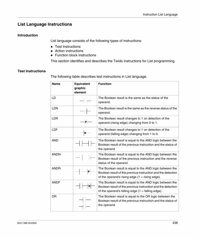
Instruction List Language
List Language Instructions
Introduction
List language consists of the following types of instructions:
Test InstructionsAction instructionsFunction block instructions
This section identifies and describes the Twido instructions for List programming.
Test Instructions
The following table describes test instructions in List language.
Name Equivalent graphic element
Function
LD The Boolean result is the same as the status of the operand.
LDN The Boolean result is the same as the reverse status of the operand.
LDR The Boolean result changes to 1 on detection of the operand (rising edge) changing from 0 to 1.
LDF The Boolean result changes to 1 on detection of the operand (falling edge) changing from 1 to 0.
AND The Boolean result is equal to the AND logic between the Boolean result of the previous instruction and the status of the operand.
ANDN The Boolean result is equal to the AND logic between the Boolean result of the previous instruction and the reverse status of the operand.
ANDR The Boolean result is equal to the AND logic between the Boolean result of the previous instruction and the detection of the operand's rising edge (1 = rising edge).
ANDF The Boolean result is equal to the AND logic between the Boolean result of the previous instruction and the detection of the operand's falling edge (1 = falling edge).
OR The Boolean result is equal to the OR logic between the Boolean result of the previous instruction and the status of the operand.
35011386 05/2009 438
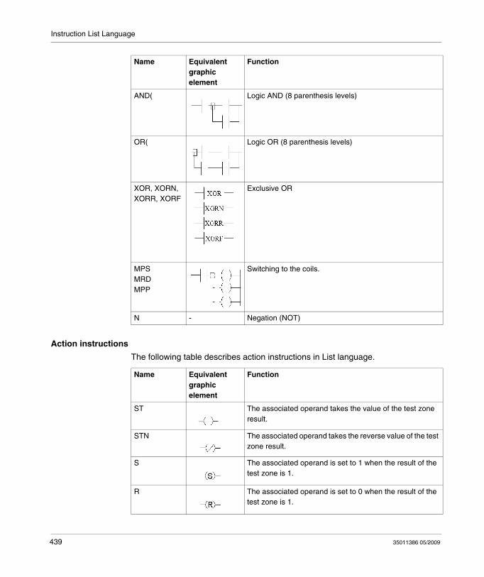
Instruction List Language
Action instructions
The following table describes action instructions in List language.
AND( Logic AND (8 parenthesis levels)
OR( Logic OR (8 parenthesis levels)
XOR, XORN, XORR, XORF
Exclusive OR
MPSMRDMPP
Switching to the coils.
N - Negation (NOT)
Name Equivalent graphic element
Function
Name Equivalent graphic element
Function
ST The associated operand takes the value of the test zone result.
STN The associated operand takes the reverse value of the test zone result.
S The associated operand is set to 1 when the result of the test zone is 1.
R The associated operand is set to 0 when the result of the test zone is 1.
439 35011386 05/2009
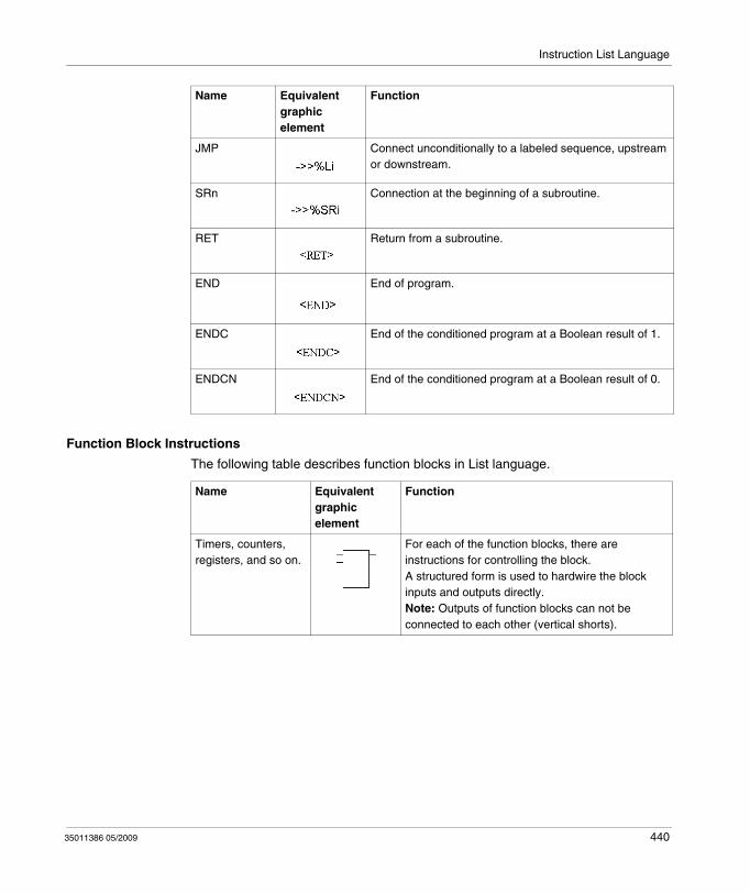
Instruction List Language
Function Block Instructions
The following table describes function blocks in List language.
JMP Connect unconditionally to a labeled sequence, upstream or downstream.
SRn Connection at the beginning of a subroutine.
RET Return from a subroutine.
END End of program.
ENDC End of the conditioned program at a Boolean result of 1.
ENDCN End of the conditioned program at a Boolean result of 0.
Name Equivalent graphic element
Function
Name Equivalent graphic element
Function
Timers, counters, registers, and so on.
For each of the function blocks, there are instructions for controlling the block. A structured form is used to hardwire the block inputs and outputs directly.Note: Outputs of function blocks can not be connected to each other (vertical shorts).
35011386 05/2009 440
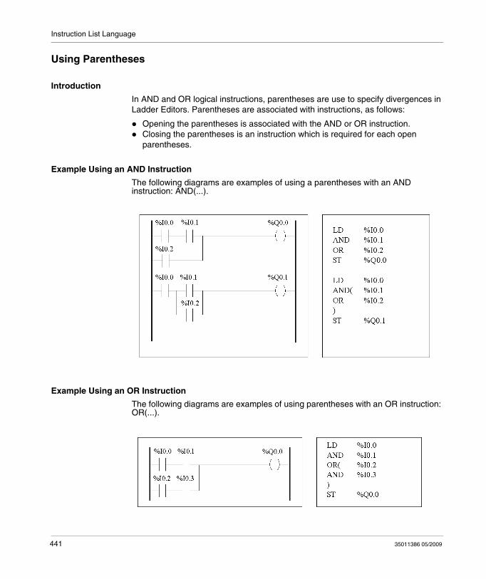
Instruction List Language
Using Parentheses
Introduction
In AND and OR logical instructions, parentheses are use to specify divergences in Ladder Editors. Parentheses are associated with instructions, as follows:
Opening the parentheses is associated with the AND or OR instruction.Closing the parentheses is an instruction which is required for each open parentheses.
Example Using an AND Instruction
The following diagrams are examples of using a parentheses with an AND instruction: AND(...).
Example Using an OR Instruction
The following diagrams are examples of using parentheses with an OR instruction: OR(...).
441 35011386 05/2009
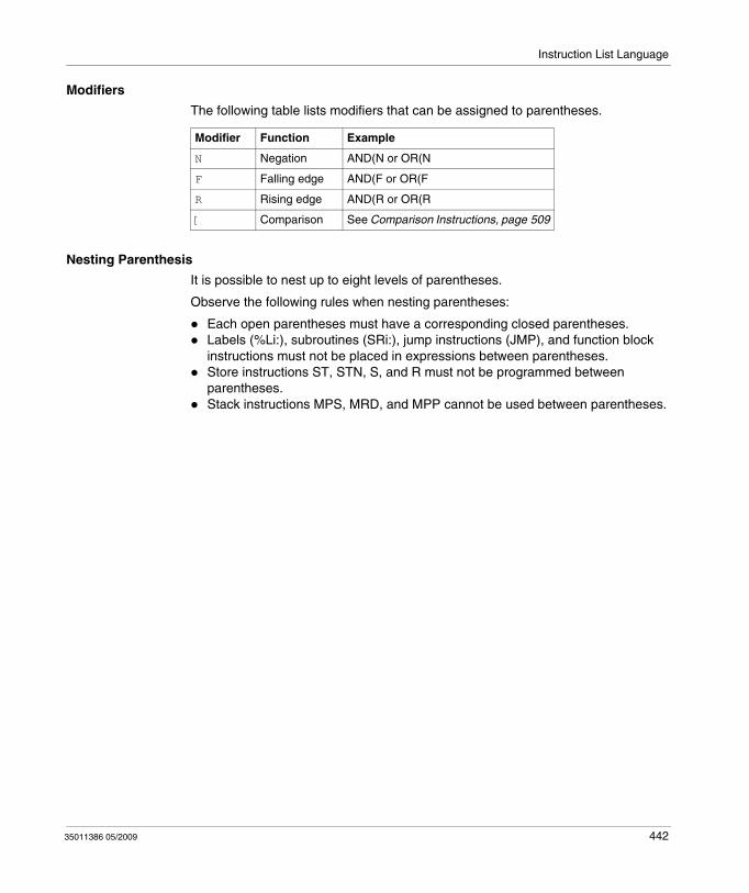
Instruction List Language
Modifiers
The following table lists modifiers that can be assigned to parentheses.
Nesting Parenthesis
It is possible to nest up to eight levels of parentheses.
Observe the following rules when nesting parentheses:
Each open parentheses must have a corresponding closed parentheses.Labels (%Li:), subroutines (SRi:), jump instructions (JMP), and function block instructions must not be placed in expressions between parentheses.Store instructions ST, STN, S, and R must not be programmed between parentheses.Stack instructions MPS, MRD, and MPP cannot be used between parentheses.
Modifier Function Example
N Negation AND(N or OR(N
F Falling edge AND(F or OR(F
R Rising edge AND(R or OR(R
[ Comparison See Comparison Instructions, page 509
35011386 05/2009 442
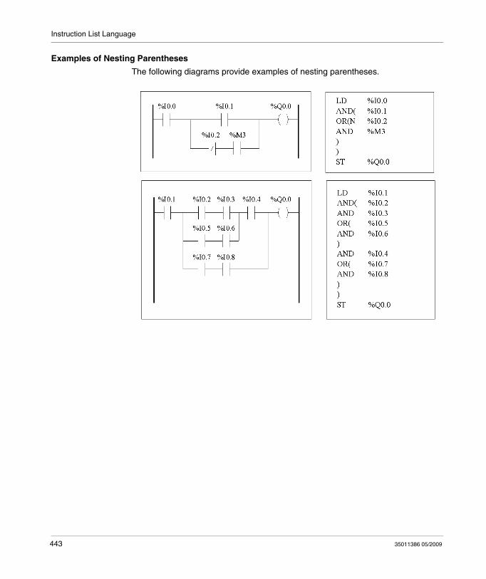
Instruction List Language
Examples of Nesting Parentheses
The following diagrams provide examples of nesting parentheses.
443 35011386 05/2009
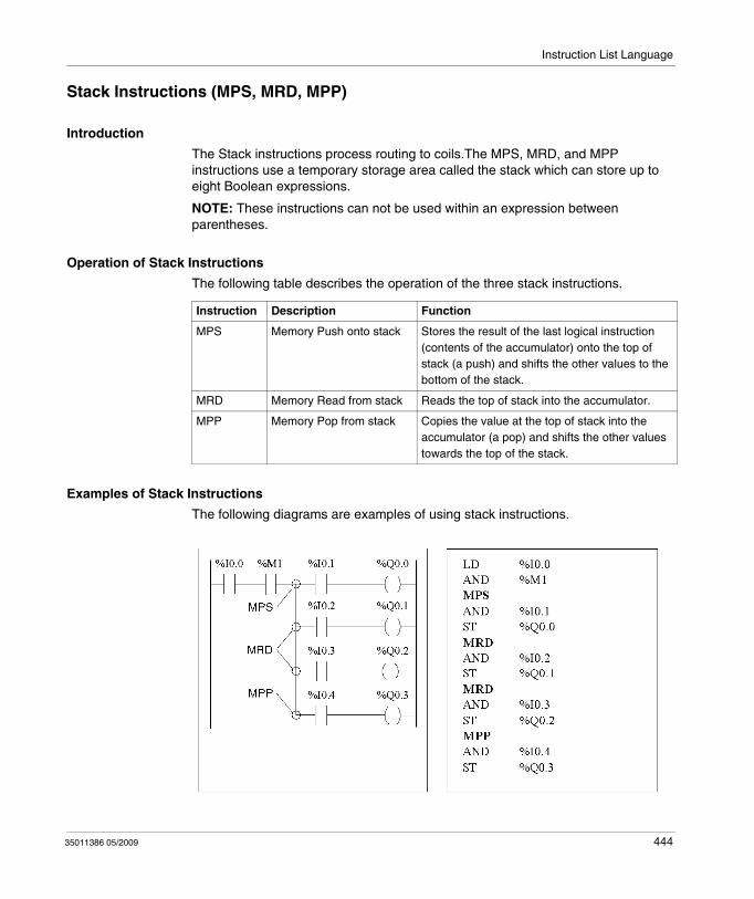
Instruction List Language
Stack Instructions (MPS, MRD, MPP)
Introduction
The Stack instructions process routing to coils.The MPS, MRD, and MPP instructions use a temporary storage area called the stack which can store up to eight Boolean expressions.
NOTE: These instructions can not be used within an expression between parentheses.
Operation of Stack Instructions
The following table describes the operation of the three stack instructions.
Examples of Stack Instructions
The following diagrams are examples of using stack instructions.
Instruction Description Function
MPS Memory Push onto stack Stores the result of the last logical instruction (contents of the accumulator) onto the top of stack (a push) and shifts the other values to the bottom of the stack.
MRD Memory Read from stack Reads the top of stack into the accumulator.
MPP Memory Pop from stack Copies the value at the top of stack into the accumulator (a pop) and shifts the other values towards the top of the stack.
35011386 05/2009 444
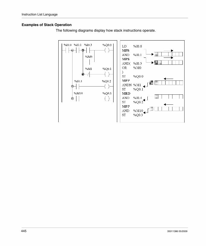
Instruction List Language
Examples of Stack Operation
The following diagrams display how stack instructions operate.
445 35011386 05/2009

35011386 05/2009
16
Grafcet
35011386 05/2009
Grafcet
Subject of this Chapter
This chapter describes programming using Grafcet Language.
What's in this Chapter?
This chapter contains the following topics:
Topic Page
Description of Grafcet Instructions 447
Description of Grafcet Program Structure 452
Actions Associated with Grafcet Steps 455
446

Grafcet
Description of Grafcet Instructions
Introduction
Grafcet instructions in TwidoSuite offer a simple method of translating a control sequence (Grafcet chart).
The maximum number of Grafcet steps depend on the type of Twido controller. The number of steps active at any one time is limited only by the total number of steps.
For the TWDLCAA10DRF and the TWDLCAA16DRF, steps 1 through 62 are available. Steps 0 and 63 are reserved for pre- and post-processing. For all other controllers, steps 1 through 95 are available.
447 35011386 05/2009
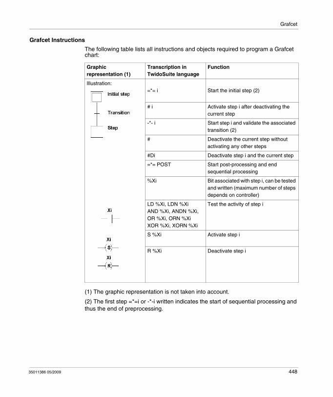
Grafcet
Grafcet Instructions
The following table lists all instructions and objects required to program a Grafcet chart:
(1) The graphic representation is not taken into account.
(2) The first step =*=i or -*-i written indicates the start of sequential processing and thus the end of preprocessing.
Graphic representation (1)
Transcription in TwidoSuite language
Function
Illustration:=*= i Start the initial step (2)
# i Activate step i after deactivating the current step
-*- i Start step i and validate the associated transition (2)
# Deactivate the current step without activating any other steps
#Di Deactivate step i and the current step
=*= POST Start post-processing and end sequential processing
%Xi Bit associated with step i, can be tested and written (maximum number of steps depends on controller)
LD %Xi, LDN %XiAND %Xi, ANDN %Xi,OR %Xi, ORN %XiXOR %Xi, XORN %Xi
Test the activity of step i
S %Xi Activate step i
R %Xi Deactivate step i
35011386 05/2009 448
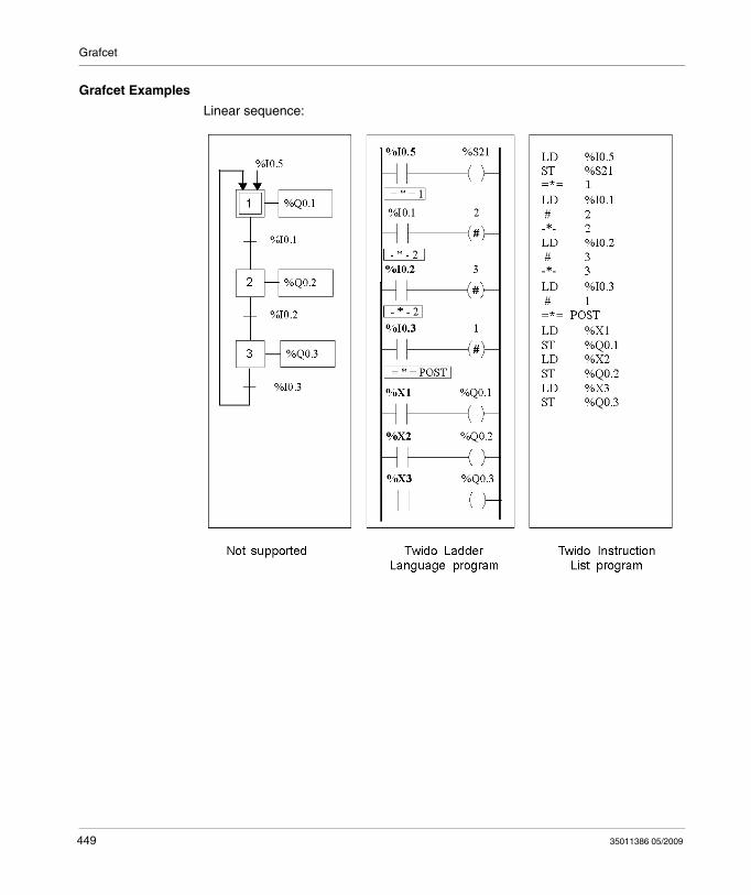
Grafcet
Grafcet Examples
Linear sequence:
449 35011386 05/2009
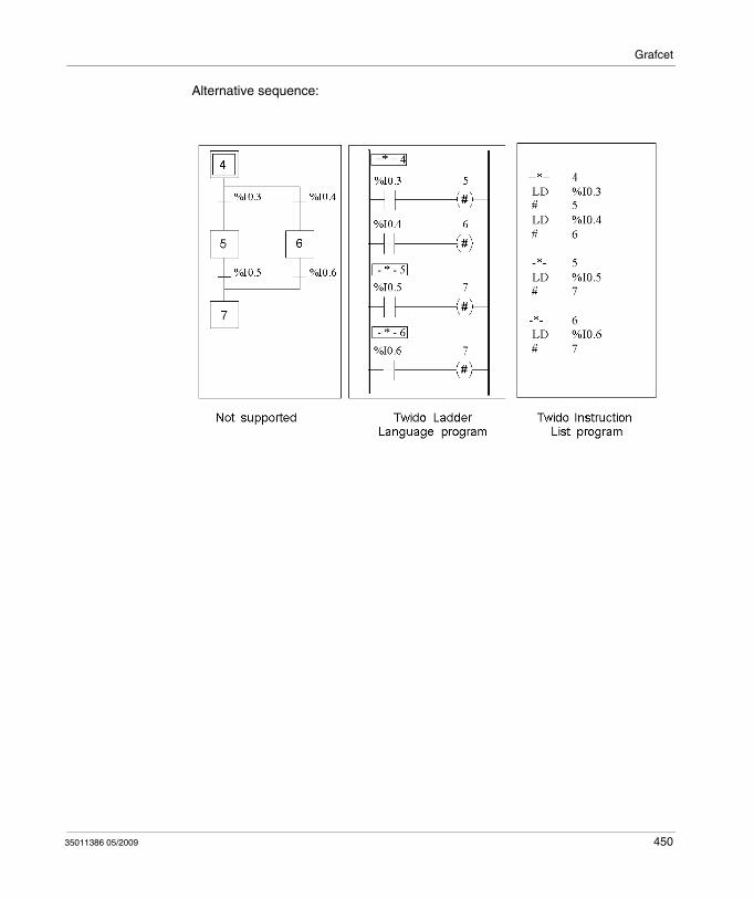
Grafcet
Alternative sequence:
35011386 05/2009 450
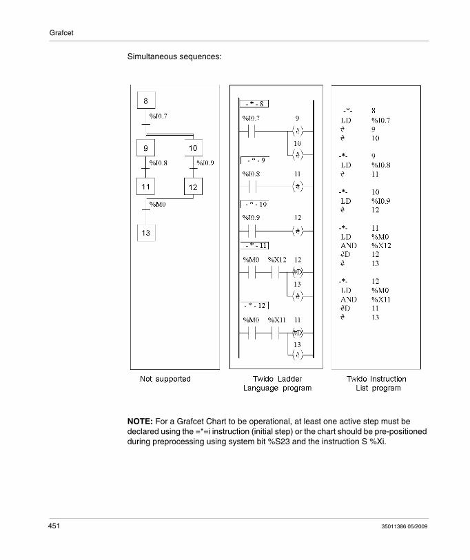
Grafcet
Simultaneous sequences:
NOTE: For a Grafcet Chart to be operational, at least one active step must be declared using the =*=i instruction (initial step) or the chart should be pre-positioned during preprocessing using system bit %S23 and the instruction S %Xi.
451 35011386 05/2009
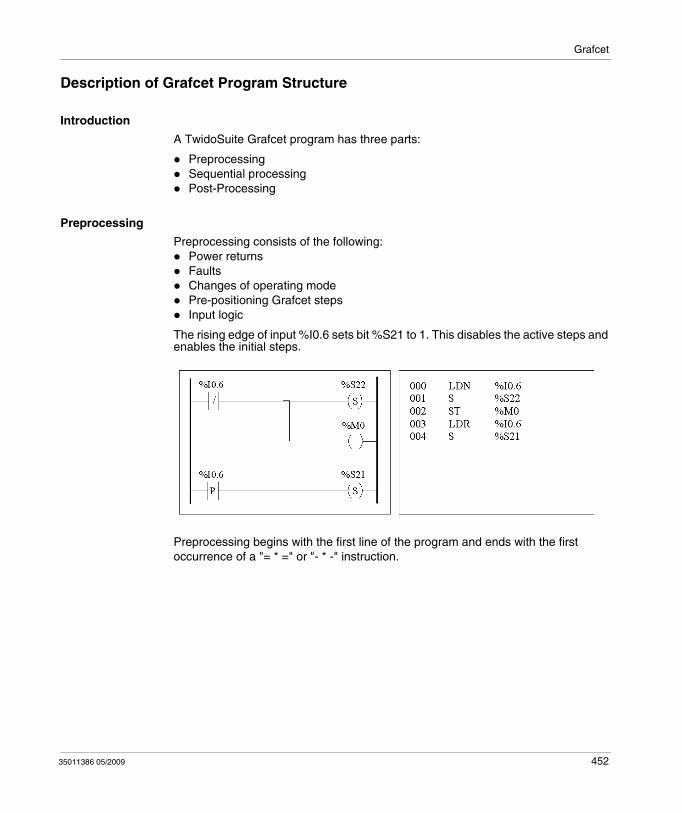
Grafcet
Description of Grafcet Program Structure
Introduction
A TwidoSuite Grafcet program has three parts:
PreprocessingSequential processingPost-Processing
Preprocessing
Preprocessing consists of the following:Power returns FaultsChanges of operating modePre-positioning Grafcet stepsInput logic
The rising edge of input %I0.6 sets bit %S21 to 1. This disables the active steps and enables the initial steps.
Preprocessing begins with the first line of the program and ends with the first occurrence of a "= * =" or "- * -" instruction.
35011386 05/2009 452
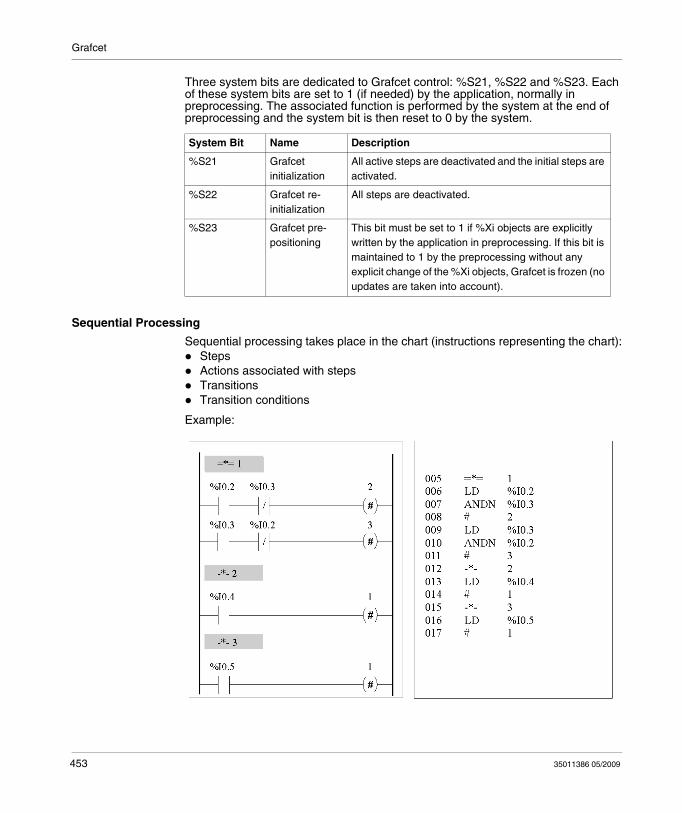
Grafcet
Three system bits are dedicated to Grafcet control: %S21, %S22 and %S23. Each of these system bits are set to 1 (if needed) by the application, normally in preprocessing. The associated function is performed by the system at the end of preprocessing and the system bit is then reset to 0 by the system.
Sequential Processing
Sequential processing takes place in the chart (instructions representing the chart):Steps Actions associated with stepsTransitionsTransition conditions
Example:
System Bit Name Description
%S21 Grafcet initialization
All active steps are deactivated and the initial steps are activated.
%S22 Grafcet re-initialization
All steps are deactivated.
%S23 Grafcet pre-positioning
This bit must be set to 1 if %Xi objects are explicitly written by the application in preprocessing. If this bit is maintained to 1 by the preprocessing without any explicit change of the %Xi objects, Grafcet is frozen (no updates are taken into account).
453 35011386 05/2009
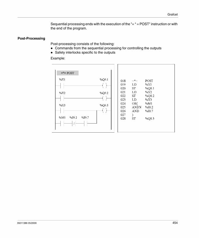
Grafcet
Sequential processing ends with the execution of the "= * = POST" instruction or with the end of the program.
Post-Processing
Post-processing consists of the following:Commands from the sequential processing for controlling the outputsSafety interlocks specific to the outputs
Example:
35011386 05/2009 454
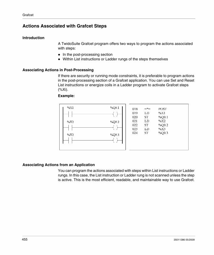
Grafcet
Actions Associated with Grafcet Steps
Introduction
A TwidoSuite Grafcet program offers two ways to program the actions associated with steps:
In the post-processing sectionWithin List instructions or Ladder rungs of the steps themselves
Associating Actions in Post-Processing
If there are security or running mode constraints, it is preferable to program actions in the post-processing section of a Grafcet application. You can use Set and Reset List instructions or energize coils in a Ladder program to activate Grafcet steps (%Xi).
Example:
Associating Actions from an Application
You can program the actions associated with steps within List instructions or Ladder rungs. In this case, the List instruction or Ladder rung is not scanned unless the step is active. This is the most efficient, readable, and maintainable way to use Grafcet.
455 35011386 05/2009
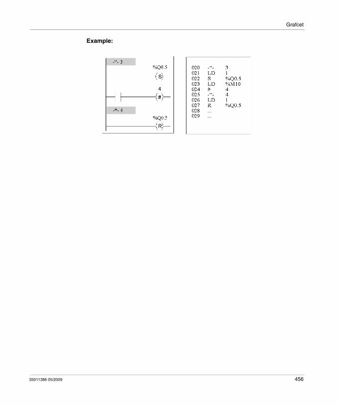
Grafcet
Example:
35011386 05/2009 456

Grafcet
457 35011386 05/2009
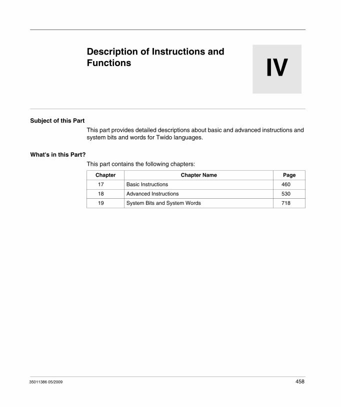
35011386 05/2009
IV
Instructions and Functions
35011386 05/2009
Description of Instructions and Functions
Subject of this Part
This part provides detailed descriptions about basic and advanced instructions and system bits and words for Twido languages.
What's in this Part?
This part contains the following chapters:
Chapter Chapter Name Page
17 Basic Instructions 460
18 Advanced Instructions 530
19 System Bits and System Words 718
458

Instructions and Functions
459 35011386 05/2009
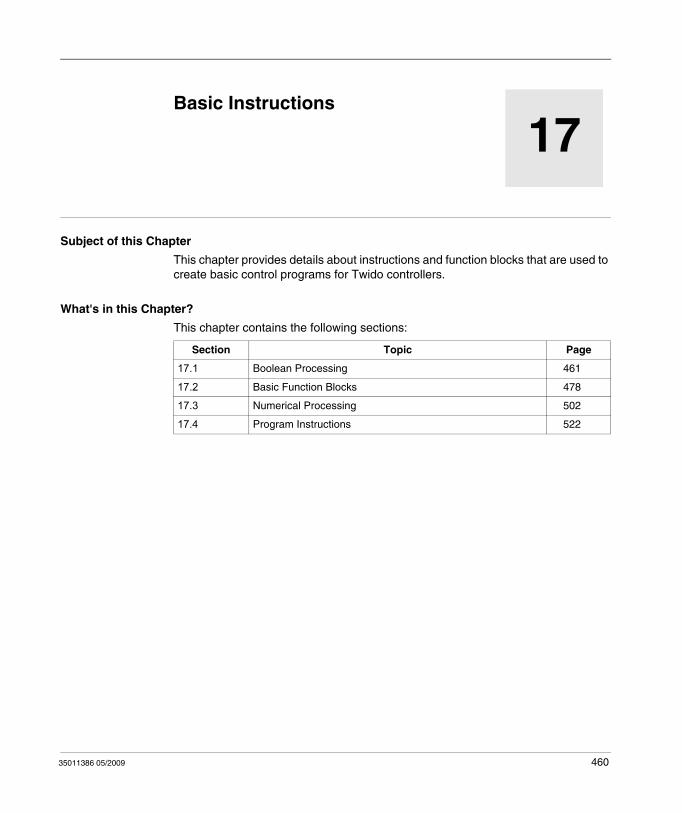
35011386 05/2009
17
Basic Instructions
35011386 05/2009
Basic Instructions
Subject of this Chapter
This chapter provides details about instructions and function blocks that are used to create basic control programs for Twido controllers.
What's in this Chapter?
This chapter contains the following sections:
Section Topic Page
17.1 Boolean Processing 461
17.2 Basic Function Blocks 478
17.3 Numerical Processing 502
17.4 Program Instructions 522
460
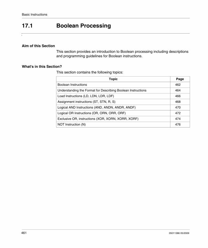
Basic Instructions
17.1 Boolean Processing
Aim of this Section
This section provides an introduction to Boolean processing including descriptions and programming guidelines for Boolean instructions.
What's in this Section?
This section contains the following topics:
Topic Page
Boolean Instructions 462
Understanding the Format for Describing Boolean Instructions 464
Load Instructions (LD, LDN, LDR, LDF) 466
Assignment instructions (ST, STN, R, S) 468
Logical AND Instructions (AND, ANDN, ANDR, ANDF) 470
Logical OR Instructions (OR, ORN, ORR, ORF) 472
Exclusive OR, instructions (XOR, XORN, XORR, XORF) 474
NOT Instruction (N) 476
461 35011386 05/2009
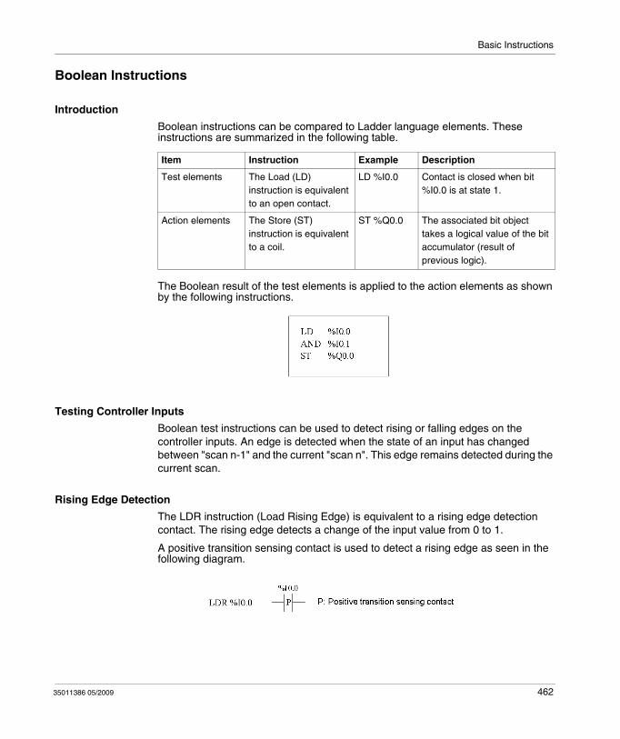
Basic Instructions
Boolean Instructions
Introduction
Boolean instructions can be compared to Ladder language elements. These instructions are summarized in the following table.
The Boolean result of the test elements is applied to the action elements as shown by the following instructions.
Testing Controller Inputs
Boolean test instructions can be used to detect rising or falling edges on the controller inputs. An edge is detected when the state of an input has changed between "scan n-1" and the current "scan n". This edge remains detected during the current scan.
Rising Edge Detection
The LDR instruction (Load Rising Edge) is equivalent to a rising edge detection contact. The rising edge detects a change of the input value from 0 to 1.
A positive transition sensing contact is used to detect a rising edge as seen in the following diagram.
Item Instruction Example Description
Test elements The Load (LD) instruction is equivalent to an open contact.
LD %I0.0 Contact is closed when bit %I0.0 is at state 1.
Action elements The Store (ST) instruction is equivalent to a coil.
ST %Q0.0 The associated bit object takes a logical value of the bit accumulator (result of previous logic).
35011386 05/2009 462
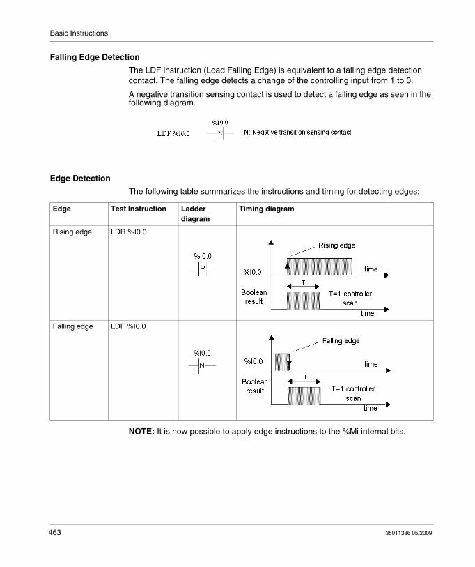
Basic Instructions
Falling Edge Detection
The LDF instruction (Load Falling Edge) is equivalent to a falling edge detection contact. The falling edge detects a change of the controlling input from 1 to 0.
A negative transition sensing contact is used to detect a falling edge as seen in the following diagram.
Edge Detection
The following table summarizes the instructions and timing for detecting edges:
NOTE: It is now possible to apply edge instructions to the %Mi internal bits.
Edge Test Instruction Ladder diagram
Timing diagram
Rising edge LDR %I0.0
Falling edge LDF %I0.0
463 35011386 05/2009
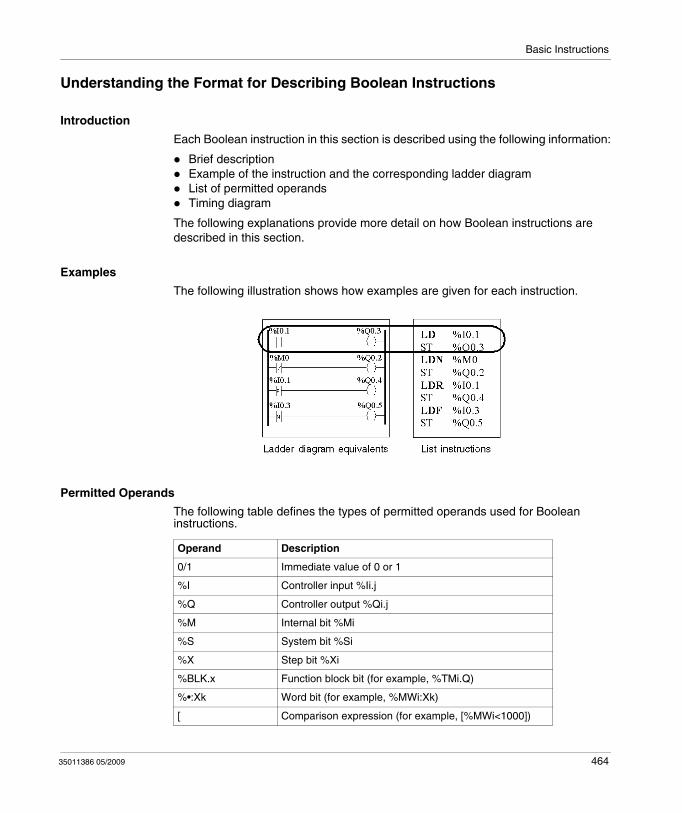
Basic Instructions
Understanding the Format for Describing Boolean Instructions
Introduction
Each Boolean instruction in this section is described using the following information:
Brief descriptionExample of the instruction and the corresponding ladder diagramList of permitted operandsTiming diagram
The following explanations provide more detail on how Boolean instructions are described in this section.
Examples
The following illustration shows how examples are given for each instruction.
Permitted Operands
The following table defines the types of permitted operands used for Boolean instructions.
Operand Description
0/1 Immediate value of 0 or 1
%I Controller input %Ii.j
%Q Controller output %Qi.j
%M Internal bit %Mi
%S System bit %Si
%X Step bit %Xi
%BLK.x Function block bit (for example, %TMi.Q)
%•:Xk Word bit (for example, %MWi:Xk)
[ Comparison expression (for example, [%MWi<1000])
35011386 05/2009 464
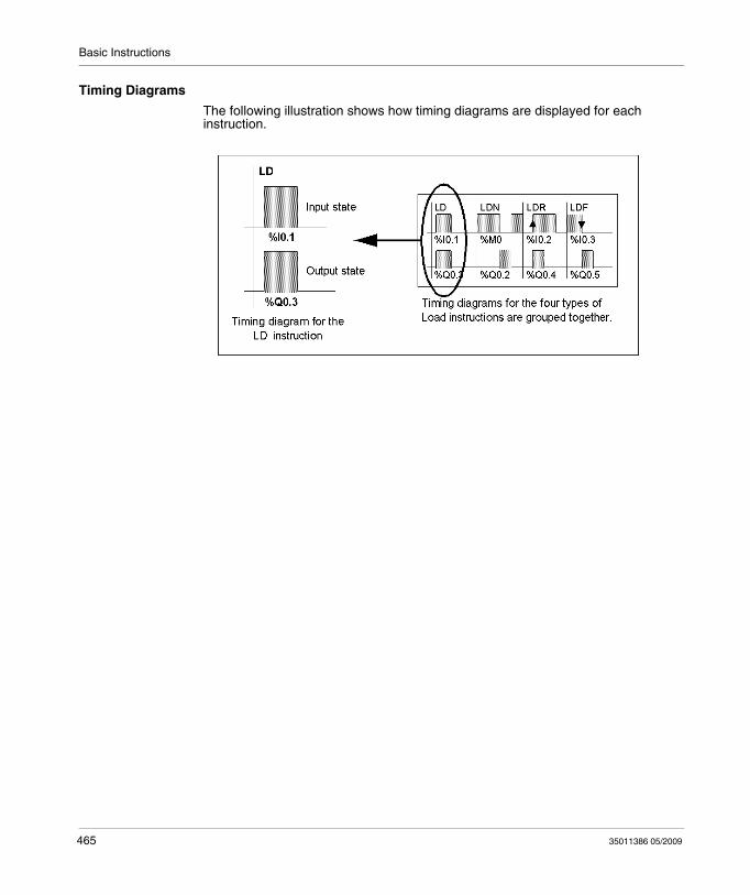
Basic Instructions
Timing Diagrams
The following illustration shows how timing diagrams are displayed for each instruction.
465 35011386 05/2009
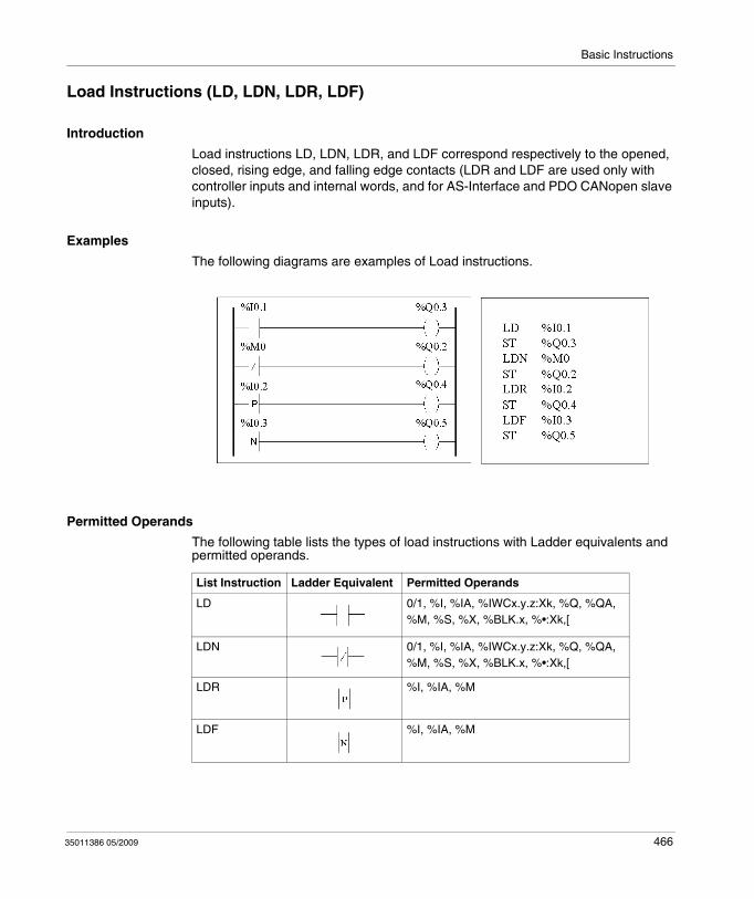
Basic Instructions
Load Instructions (LD, LDN, LDR, LDF)
Introduction
Load instructions LD, LDN, LDR, and LDF correspond respectively to the opened, closed, rising edge, and falling edge contacts (LDR and LDF are used only with controller inputs and internal words, and for AS-Interface and PDO CANopen slave inputs).
Examples
The following diagrams are examples of Load instructions.
Permitted Operands
The following table lists the types of load instructions with Ladder equivalents and permitted operands.
List Instruction Ladder Equivalent Permitted Operands
LD 0/1, %I, %IA, %IWCx.y.z:Xk, %Q, %QA, %M, %S, %X, %BLK.x, %•:Xk,[
LDN 0/1, %I, %IA, %IWCx.y.z:Xk, %Q, %QA, %M, %S, %X, %BLK.x, %•:Xk,[
LDR %I, %IA, %M
LDF %I, %IA, %M
35011386 05/2009 466
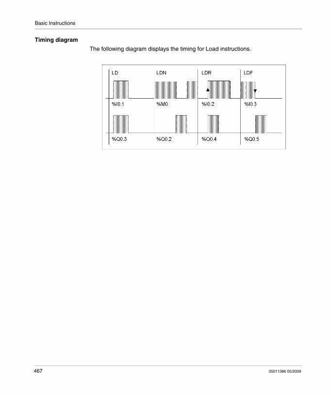
Basic Instructions
Timing diagram
The following diagram displays the timing for Load instructions.
467 35011386 05/2009
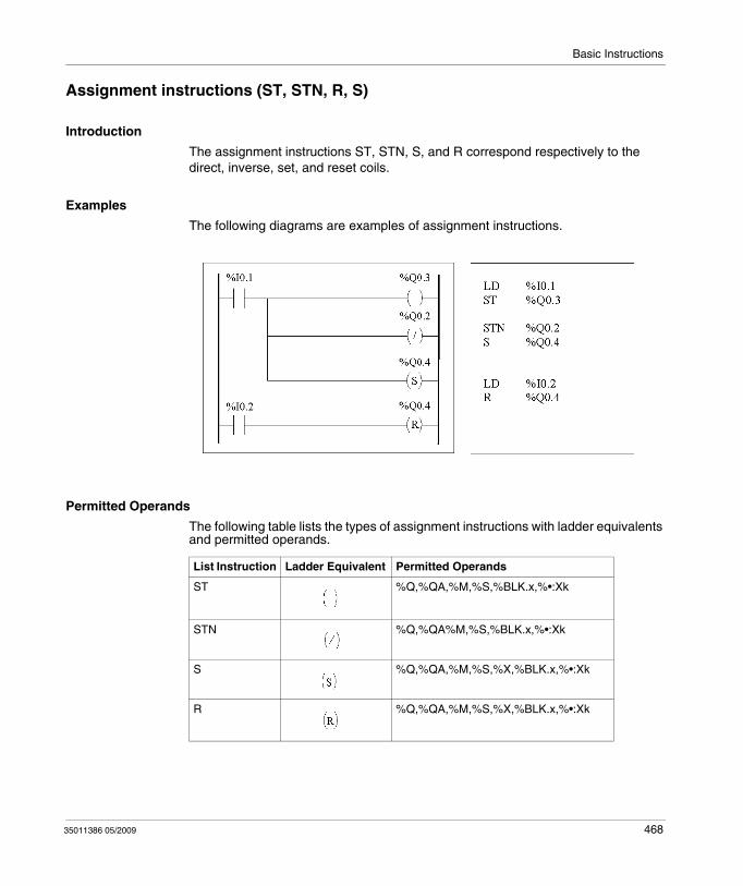
Basic Instructions
Assignment instructions (ST, STN, R, S)
Introduction
The assignment instructions ST, STN, S, and R correspond respectively to the direct, inverse, set, and reset coils.
Examples
The following diagrams are examples of assignment instructions.
Permitted Operands
The following table lists the types of assignment instructions with ladder equivalents and permitted operands.
List Instruction Ladder Equivalent Permitted Operands
ST %Q,%QA,%M,%S,%BLK.x,%•:Xk
STN %Q,%QA%M,%S,%BLK.x,%•:Xk
S %Q,%QA,%M,%S,%X,%BLK.x,%•:Xk
R %Q,%QA,%M,%S,%X,%BLK.x,%•:Xk
35011386 05/2009 468
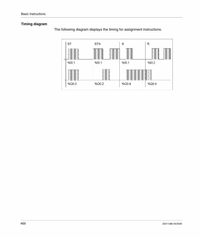
Basic Instructions
Timing diagram
The following diagram displays the timing for assignment instructions.
469 35011386 05/2009
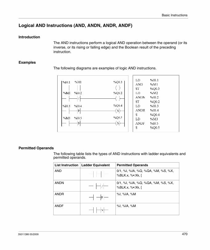
Basic Instructions
Logical AND Instructions (AND, ANDN, ANDR, ANDF)
Introduction
The AND instructions perform a logical AND operation between the operand (or its inverse, or its rising or falling edge) and the Boolean result of the preceding instruction.
Examples
The following diagrams are examples of logic AND instructions.
Permitted Operands
The following table lists the types of AND instructions with ladder equivalents and permitted operands.
List Instruction Ladder Equivalent Permitted Operands
AND 0/1, %I, %IA, %Q, %QA, %M, %S, %X, %BLK.x, %•:Xk, [
ANDN 0/1, %I, %IA, %Q, %QA, %M, %S, %X, %BLK.x, %•:Xk, [
ANDR %I, %IA, %M
ANDF %I, %IA, %M
35011386 05/2009 470
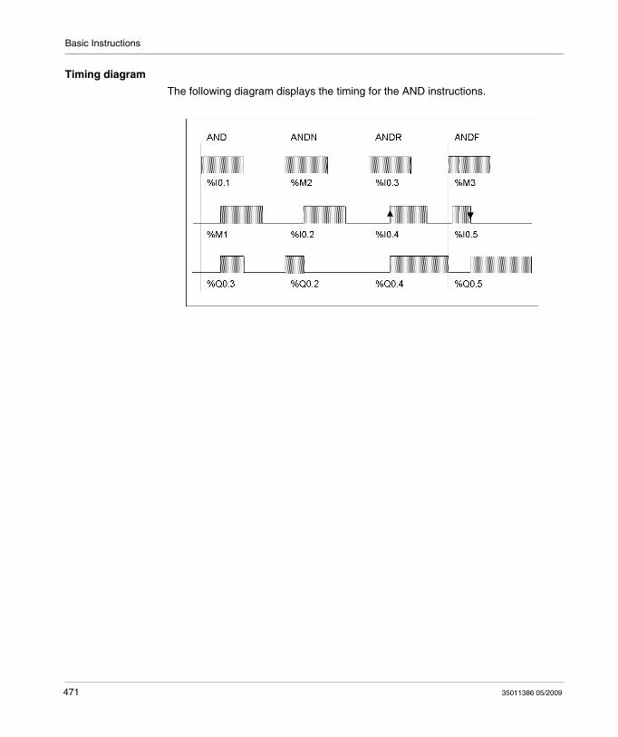
Basic Instructions
Timing diagram
The following diagram displays the timing for the AND instructions.
471 35011386 05/2009
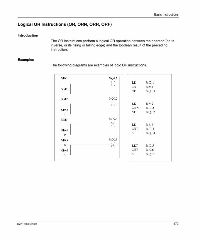
Basic Instructions
Logical OR Instructions (OR, ORN, ORR, ORF)
Introduction
The OR instructions perform a logical OR operation between the operand (or its inverse, or its rising or falling edge) and the Boolean result of the preceding instruction.
Examples
The following diagrams are examples of logic OR instructions.
35011386 05/2009 472
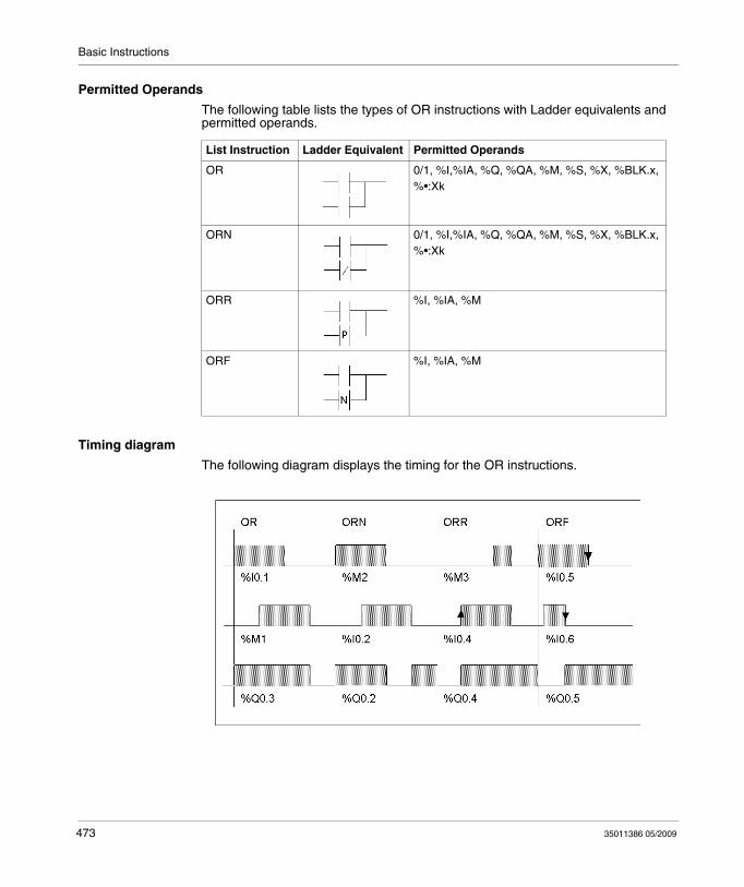
Basic Instructions
Permitted Operands
The following table lists the types of OR instructions with Ladder equivalents and permitted operands.
Timing diagram
The following diagram displays the timing for the OR instructions.
List Instruction Ladder Equivalent Permitted Operands
OR 0/1, %I,%IA, %Q, %QA, %M, %S, %X, %BLK.x, %•:Xk
ORN 0/1, %I,%IA, %Q, %QA, %M, %S, %X, %BLK.x, %•:Xk
ORR %I, %IA, %M
ORF %I, %IA, %M
473 35011386 05/2009
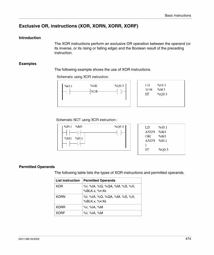
Basic Instructions
Exclusive OR, instructions (XOR, XORN, XORR, XORF)
Introduction
The XOR instructions perform an exclusive OR operation between the operand (or its inverse, or its rising or falling edge) and the Boolean result of the preceding instruction.
Examples
The following example shows the use of XOR instructions.
Permitted Operands
The following table lists the types of XOR instructions and permitted operands.
List instruction Permitted Operands
XOR %I, %IA, %Q, %QA, %M, %S, %X, %BLK.x, %•:Xk
XORN %I, %IA, %Q, %QA, %M, %S, %X, %BLK.x, %•:Xk
XORR %I, %IA, %M
XORF %I, %IA, %M
35011386 05/2009 474
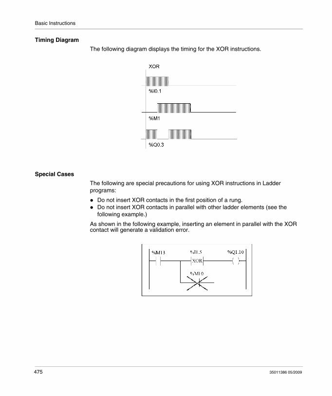
Basic Instructions
Timing Diagram
The following diagram displays the timing for the XOR instructions.
Special Cases
The following are special precautions for using XOR instructions in Ladder programs:
Do not insert XOR contacts in the first position of a rung.Do not insert XOR contacts in parallel with other ladder elements (see the following example.)
As shown in the following example, inserting an element in parallel with the XOR contact will generate a validation error.
475 35011386 05/2009
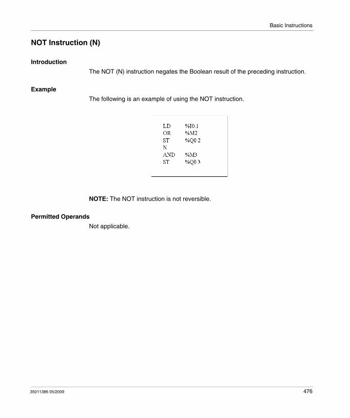
Basic Instructions
NOT Instruction (N)
Introduction
The NOT (N) instruction negates the Boolean result of the preceding instruction.
Example
The following is an example of using the NOT instruction.
NOTE: The NOT instruction is not reversible.
Permitted Operands
Not applicable.
35011386 05/2009 476
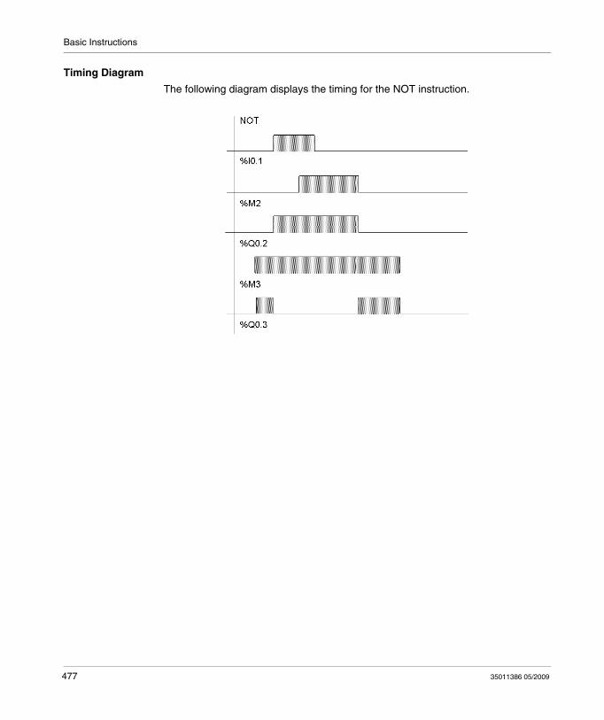
Basic Instructions
Timing Diagram
The following diagram displays the timing for the NOT instruction.
477 35011386 05/2009
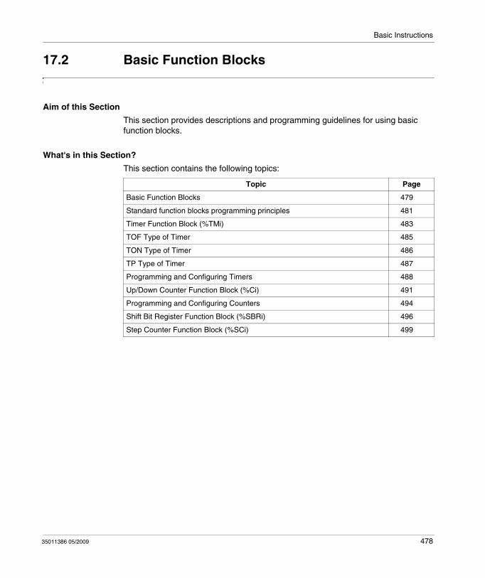
Basic Instructions
17.2 Basic Function Blocks
Aim of this Section
This section provides descriptions and programming guidelines for using basic function blocks.
What's in this Section?
This section contains the following topics:
Topic Page
Basic Function Blocks 479
Standard function blocks programming principles 481
Timer Function Block (%TMi) 483
TOF Type of Timer 485
TON Type of Timer 486
TP Type of Timer 487
Programming and Configuring Timers 488
Up/Down Counter Function Block (%Ci) 491
Programming and Configuring Counters 494
Shift Bit Register Function Block (%SBRi) 496
Step Counter Function Block (%SCi) 499
35011386 05/2009 478
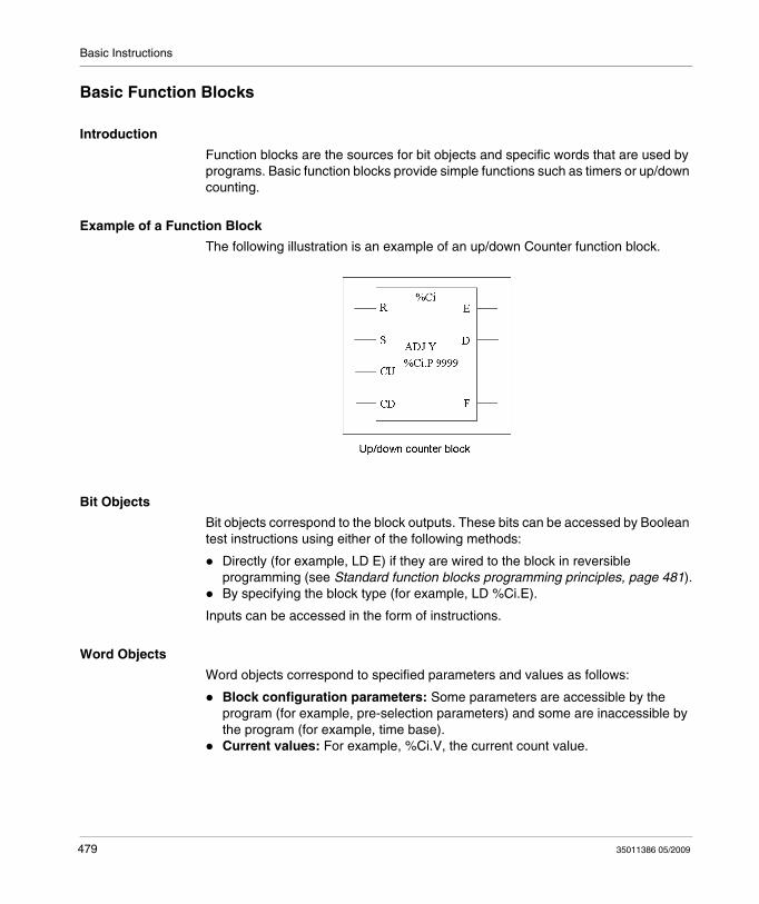
Basic Instructions
Basic Function Blocks
Introduction
Function blocks are the sources for bit objects and specific words that are used by programs. Basic function blocks provide simple functions such as timers or up/down counting.
Example of a Function Block
The following illustration is an example of an up/down Counter function block.
Bit Objects
Bit objects correspond to the block outputs. These bits can be accessed by Boolean test instructions using either of the following methods:
Directly (for example, LD E) if they are wired to the block in reversible programming (see Standard function blocks programming principles, page 481).By specifying the block type (for example, LD %Ci.E).
Inputs can be accessed in the form of instructions.
Word Objects
Word objects correspond to specified parameters and values as follows:
Block configuration parameters: Some parameters are accessible by the program (for example, pre-selection parameters) and some are inaccessible by the program (for example, time base).Current values: For example, %Ci.V, the current count value.
479 35011386 05/2009
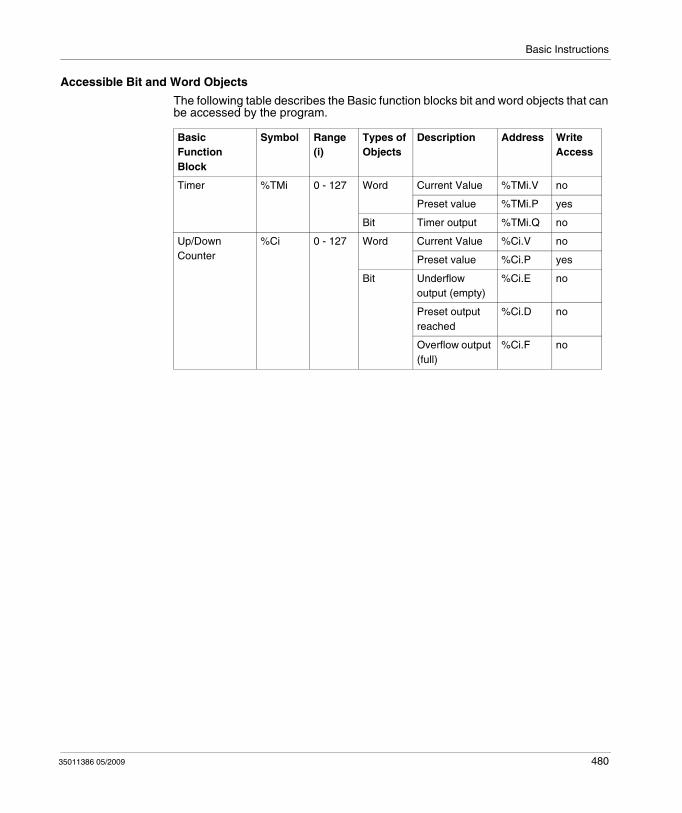
Basic Instructions
Accessible Bit and Word Objects
The following table describes the Basic function blocks bit and word objects that can be accessed by the program.
Basic Function Block
Symbol Range (i)
Types of Objects
Description Address Write Access
Timer %TMi 0 - 127 Word Current Value %TMi.V no
Preset value %TMi.P yes
Bit Timer output %TMi.Q no
Up/Down Counter
%Ci 0 - 127 Word Current Value %Ci.V no
Preset value %Ci.P yes
Bit Underflow output (empty)
%Ci.E no
Preset output reached
%Ci.D no
Overflow output (full)
%Ci.F no
35011386 05/2009 480
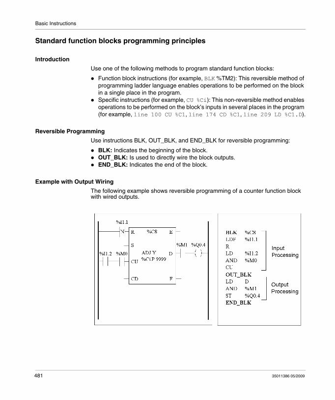
Basic Instructions
Standard function blocks programming principles
Introduction
Use one of the following methods to program standard function blocks:
Function block instructions (for example, BLK %TM2): This reversible method of programming ladder language enables operations to be performed on the block in a single place in the program.Specific instructions (for example, CU %Ci): This non-reversible method enables operations to be performed on the block’s inputs in several places in the program (for example, line 100 CU %C1, line 174 CD %C1, line 209 LD %C1.D).
Reversible Programming
Use instructions BLK, OUT_BLK, and END_BLK for reversible programming:
BLK: Indicates the beginning of the block.OUT_BLK: Is used to directly wire the block outputs.END_BLK: Indicates the end of the block.
Example with Output Wiring
The following example shows reversible programming of a counter function block with wired outputs.
481 35011386 05/2009
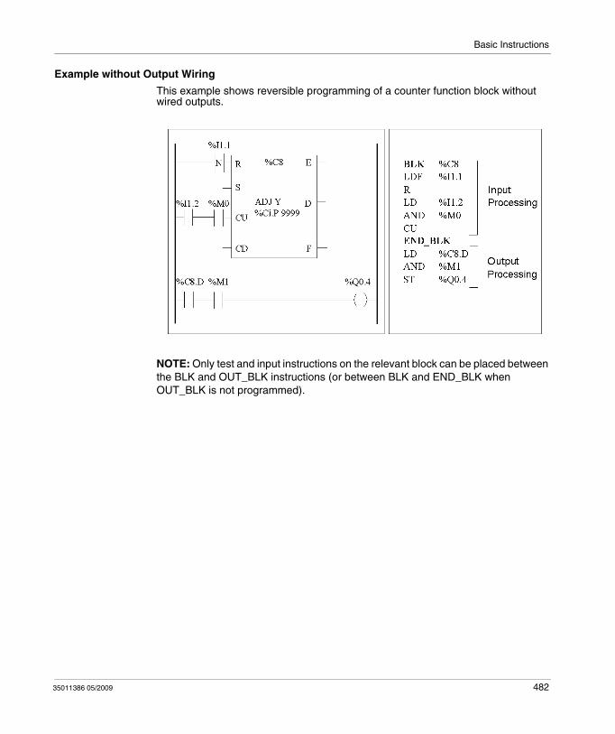
Basic Instructions
Example without Output Wiring
This example shows reversible programming of a counter function block without wired outputs.
NOTE: Only test and input instructions on the relevant block can be placed between the BLK and OUT_BLK instructions (or between BLK and END_BLK when OUT_BLK is not programmed).
35011386 05/2009 482
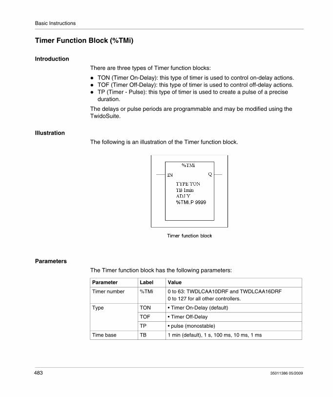
Basic Instructions
Timer Function Block (%TMi)
Introduction
There are three types of Timer function blocks:
TON (Timer On-Delay): this type of timer is used to control on-delay actions.TOF (Timer Off-Delay): this type of timer is used to control off-delay actions.TP (Timer - Pulse): this type of timer is used to create a pulse of a precise duration.
The delays or pulse periods are programmable and may be modified using the TwidoSuite.
Illustration
The following is an illustration of the Timer function block.
Parameters
The Timer function block has the following parameters:
Parameter Label Value
Timer number %TMi 0 to 63: TWDLCAA10DRF and TWDLCAA16DRF0 to 127 for all other controllers.
Type TON • Timer On-Delay (default)
TOF • Timer Off-Delay
TP • pulse (monostable)
Time base TB 1 min (default), 1 s, 100 ms, 10 ms, 1 ms
483 35011386 05/2009
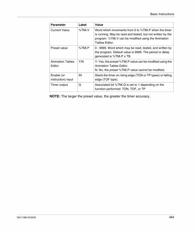
Basic Instructions
NOTE: The larger the preset value, the greater the timer accuracy.
Current Value %TMi.V Word which increments from 0 to %TMi.P when the timer is running. May be read and tested, but not written by the program. %TMi.V can be modified using the Animation Tables Editor.
Preset value %TMi.P 0 - 9999. Word which may be read, tested, and written by the program. Default value is 9999. The period or delay generated is %TMi.P x TB.
Animation Tables Editor
Y/N Y: Yes, the preset %TMi.P value can be modified using the Animation Tables Editor.N: No, the preset %TMi.P value cannot be modified.
Enable (or instruction) input
IN Starts the timer on rising edge (TON or TP types) or falling edge (TOF type).
Timer output Q Associated bit %TMi.Q is set to 1 depending on the function performed: TON, TOF, or TP
Parameter Label Value
35011386 05/2009 484
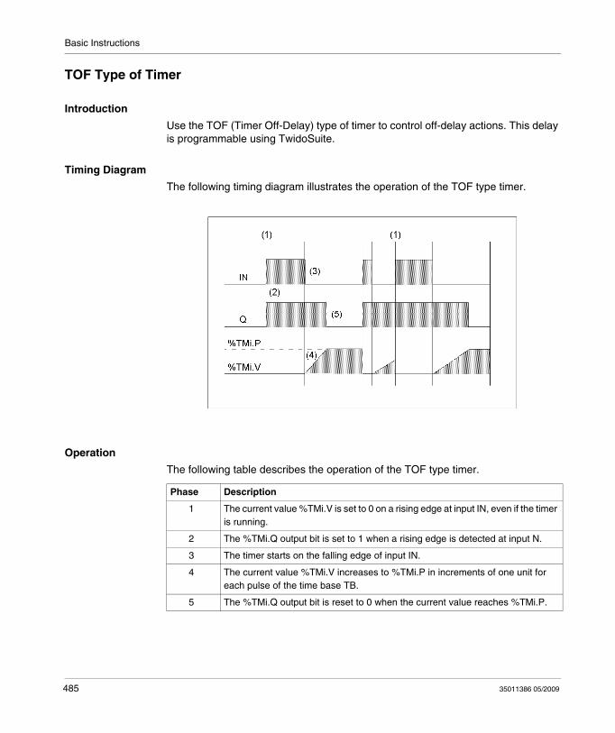
Basic Instructions
TOF Type of Timer
Introduction
Use the TOF (Timer Off-Delay) type of timer to control off-delay actions. This delay is programmable using TwidoSuite.
Timing Diagram
The following timing diagram illustrates the operation of the TOF type timer.
Operation
The following table describes the operation of the TOF type timer.
Phase Description
1 The current value %TMi.V is set to 0 on a rising edge at input IN, even if the timer is running.
2 The %TMi.Q output bit is set to 1 when a rising edge is detected at input N.
3 The timer starts on the falling edge of input IN.
4 The current value %TMi.V increases to %TMi.P in increments of one unit for each pulse of the time base TB.
5 The %TMi.Q output bit is reset to 0 when the current value reaches %TMi.P.
485 35011386 05/2009
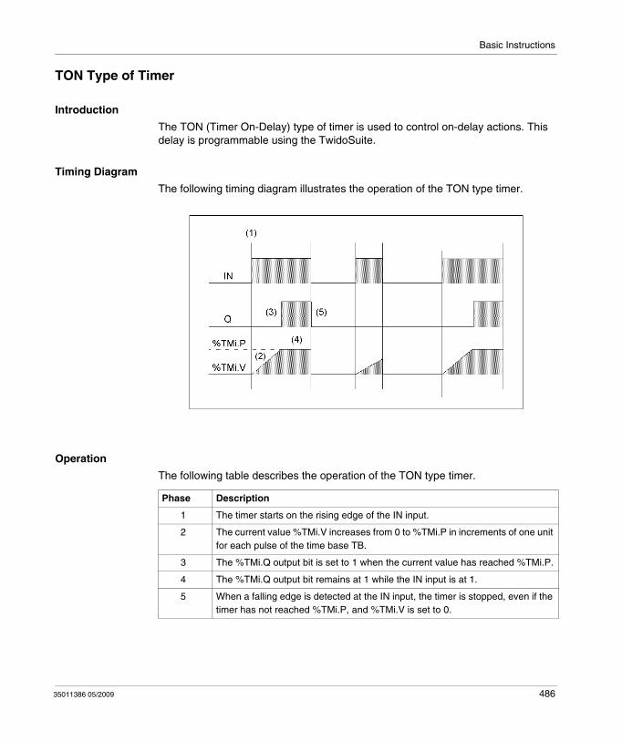
Basic Instructions
TON Type of Timer
Introduction
The TON (Timer On-Delay) type of timer is used to control on-delay actions. This delay is programmable using the TwidoSuite.
Timing Diagram
The following timing diagram illustrates the operation of the TON type timer.
Operation
The following table describes the operation of the TON type timer.
Phase Description
1 The timer starts on the rising edge of the IN input.
2 The current value %TMi.V increases from 0 to %TMi.P in increments of one unit for each pulse of the time base TB.
3 The %TMi.Q output bit is set to 1 when the current value has reached %TMi.P.
4 The %TMi.Q output bit remains at 1 while the IN input is at 1.
5 When a falling edge is detected at the IN input, the timer is stopped, even if the timer has not reached %TMi.P, and %TMi.V is set to 0.
35011386 05/2009 486
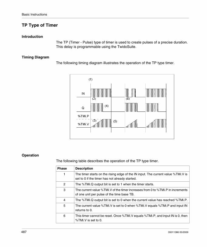
Basic Instructions
TP Type of Timer
Introduction
The TP (Timer - Pulse) type of timer is used to create pulses of a precise duration. This delay is programmable using the TwidoSuite.
Timing Diagram
The following timing diagram illustrates the operation of the TP type timer.
Operation
The following table describes the operation of the TP type timer.
Phase Description
1 The timer starts on the rising edge of the IN input. The current value %TMi.V is set to 0 if the timer has not already started.
2 The %TMi.Q output bit is set to 1 when the timer starts.
3 The current value %TMi.V of the timer increases from 0 to %TMi.P in increments of one unit per pulse of the time base TB.
4 The %TMi.Q output bit is set to 0 when the current value has reached %TMi.P.
5 The current value %TMi.V is set to 0 when %TMi.V equals %TMi.P and input IN returns to 0.
6 This timer cannot be reset. Once %TMi.V equals %TMi.P, and input IN is 0, then %TMi.V is set to 0.
487 35011386 05/2009
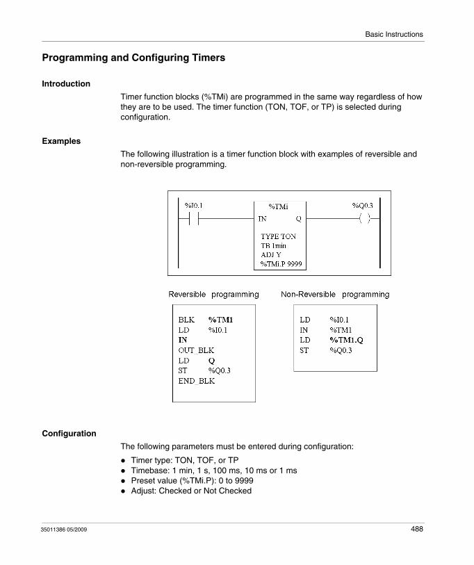
Basic Instructions
Programming and Configuring Timers
Introduction
Timer function blocks (%TMi) are programmed in the same way regardless of how they are to be used. The timer function (TON, TOF, or TP) is selected during configuration.
Examples
The following illustration is a timer function block with examples of reversible and non-reversible programming.
Configuration
The following parameters must be entered during configuration:
Timer type: TON, TOF, or TPTimebase: 1 min, 1 s, 100 ms, 10 ms or 1 msPreset value (%TMi.P): 0 to 9999Adjust: Checked or Not Checked
35011386 05/2009 488
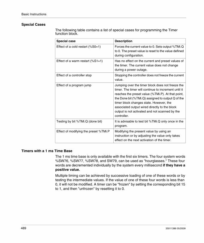
Basic Instructions
Special Cases
The following table contains a list of special cases for programming the Timer function block.
Timers with a 1 ms Time Base
The 1 ms time base is only available with the first six timers. The four system words %SW76, %SW77, %SW78, and SW79, can be used as "hourglasses." These four words are decremented individually by the system every millisecond if they have a positive value.
Multiple timing can be achieved by successive loading of one of these words or by testing the intermediate values. If the value of one of these four words is less than 0, it will not be modified. A timer can be "frozen" by setting the corresponding bit 15 to 1, and then "unfrozen" by resetting it to 0.
Special case Description
Effect of a cold restart (%S0=1) Forces the current value to 0. Sets output %TMi.Q to 0. The preset value is reset to the value defined during configuration.
Effect of a warm restart (%S1=1) Has no effect on the current and preset values of the timer. The current value does not change during a power outage.
Effect of a controller stop Stopping the controller does not freeze the current value.
Effect of a program jump Jumping over the timer block does not freeze the timer. The timer will continue to increment until it reaches the preset value (%TMi.P). At that point, the Done bit (%TMi.Q) assigned to output Q of the timer block changes state. However, the associated output wired directly to the block output is not activated and not scanned by the controller.
Testing by bit %TMi.Q (done bit) It is advisable to test bit %TMi.Q only once in the program.
Effect of modifying the preset %TMi.P Modifying the present value by using an instruction or by adjusting the value only takes effect on the next activation of the timer.
489 35011386 05/2009
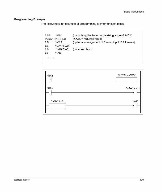
Basic Instructions
Programming Example
The following is an example of programming a timer function block.
35011386 05/2009 490
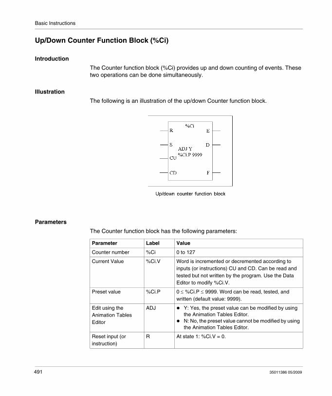
Basic Instructions
Up/Down Counter Function Block (%Ci)
Introduction
The Counter function block (%Ci) provides up and down counting of events. These two operations can be done simultaneously.
Illustration
The following is an illustration of the up/down Counter function block.
Parameters
The Counter function block has the following parameters:
Parameter Label Value
Counter number %Ci 0 to 127
Current Value %Ci.V Word is incremented or decremented according to inputs (or instructions) CU and CD. Can be read and tested but not written by the program. Use the Data Editor to modify %Ci.V.
Preset value %Ci.P 0 ≤ %Ci.P ≤ 9999. Word can be read, tested, and written (default value: 9999).
Edit using the Animation Tables Editor
ADJ Y: Yes, the preset value can be modified by using the Animation Tables Editor.N: No, the preset value cannot be modified by using the Animation Tables Editor.
Reset input (or instruction)
R At state 1: %Ci.V = 0.
491 35011386 05/2009
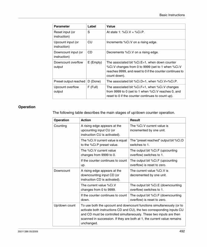
Basic Instructions
Operation
The following table describes the main stages of up/down counter operation.
Reset input (or instruction)
S At state 1: %Ci.V = %Ci.P.
Upcount input (or instruction)
CU Increments %Ci.V on a rising edge.
Downcount input (or instruction)
CD Decrements %Ci.V on a rising edge.
Downcount overflow output
E (Empty) The associated bit %Ci.E=1, when down counter %Ci.V changes from 0 to 9999 (set to 1 when %Ci.V reaches 9999, and reset to 0 if the counter continues to count down).
Preset output reached D (Done) The associated bit %Ci.D=1, when %Ci.V=%Ci.P.
Upcount overflow output
F (Full) The associated bit %Ci.F=1, when %Ci.V changes from 9999 to 0 (set to 1 when %Ci.V reaches 0, and reset to 0 if the counter continues to count up).
Parameter Label Value
Operation Action Result
Counting A rising edge appears at the upcounting input CU (or instruction CU is activated).
The %Ci.V current value is incremented by one unit.
The %Ci.V current value is equal to the %Ci.P preset value.
The "preset reached" output bit %Ci.D switches to 1.
The %Ci.V current value changes from 9999 to 0.
The output bit %Ci.F (upcounting overflow) switches to 1.
If the counter continues to count up.
The output bit %Ci.F (upcounting overflow) is reset to zero.
Downcount A rising edge appears at the downcounting input CD (or instruction CD is activated).
The current value %Ci.V is decremented by one unit.
The current value %Ci.V changes from 0 to 9999.
The output bit %Ci.E (downcounting overflow) switches to 1.
If the counter continues to count down.
The output bit %Ci.F (downcounting overflow) is reset to zero.
Up/down count To use both the upcount and downcount functions simultaneously (or to activate both instructions CD and CU), the two corresponding inputs CU and CD must be controlled simultaneously. These two inputs are then scanned in succession. If they are both at 1, the current value remains unchanged.
35011386 05/2009 492
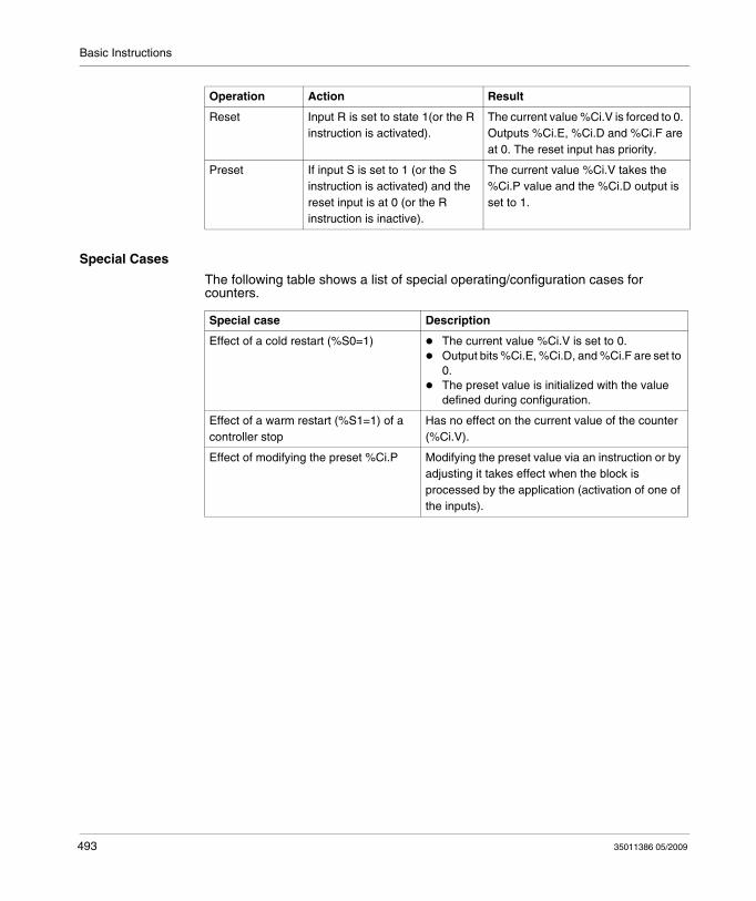
Basic Instructions
Special Cases
The following table shows a list of special operating/configuration cases for counters.
Reset Input R is set to state 1(or the R instruction is activated).
The current value %Ci.V is forced to 0. Outputs %Ci.E, %Ci.D and %Ci.F are at 0. The reset input has priority.
Preset If input S is set to 1 (or the S instruction is activated) and the reset input is at 0 (or the R instruction is inactive).
The current value %Ci.V takes the %Ci.P value and the %Ci.D output is set to 1.
Operation Action Result
Special case Description
Effect of a cold restart (%S0=1) The current value %Ci.V is set to 0.Output bits %Ci.E, %Ci.D, and %Ci.F are set to 0.The preset value is initialized with the value defined during configuration.
Effect of a warm restart (%S1=1) of a controller stop
Has no effect on the current value of the counter (%Ci.V).
Effect of modifying the preset %Ci.P Modifying the preset value via an instruction or by adjusting it takes effect when the block is processed by the application (activation of one of the inputs).
493 35011386 05/2009
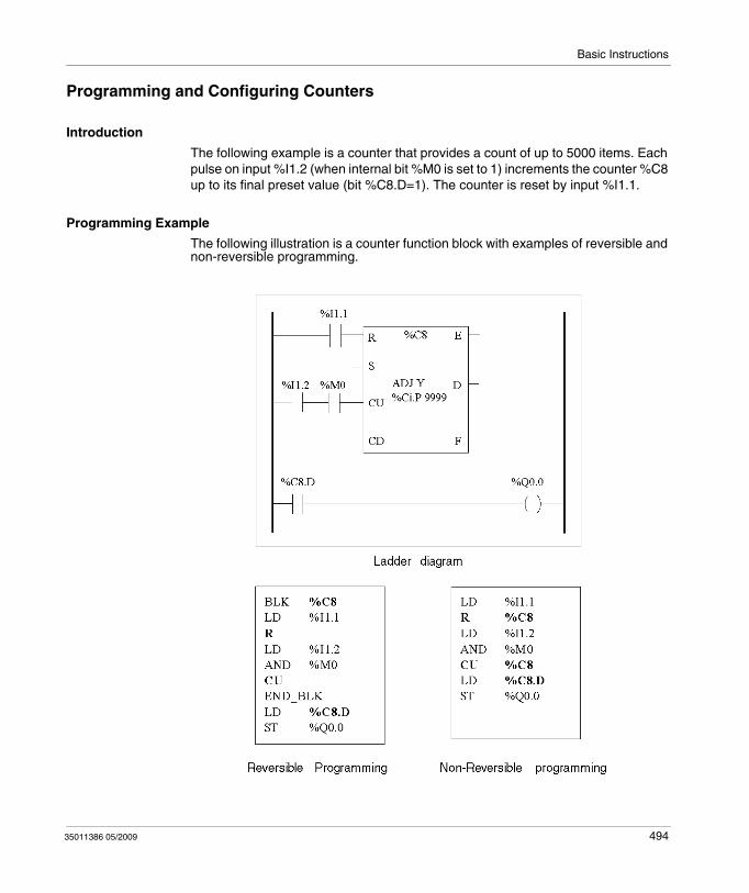
Basic Instructions
Programming and Configuring Counters
Introduction
The following example is a counter that provides a count of up to 5000 items. Each pulse on input %I1.2 (when internal bit %M0 is set to 1) increments the counter %C8 up to its final preset value (bit %C8.D=1). The counter is reset by input %I1.1.
Programming Example
The following illustration is a counter function block with examples of reversible and non-reversible programming.
35011386 05/2009 494
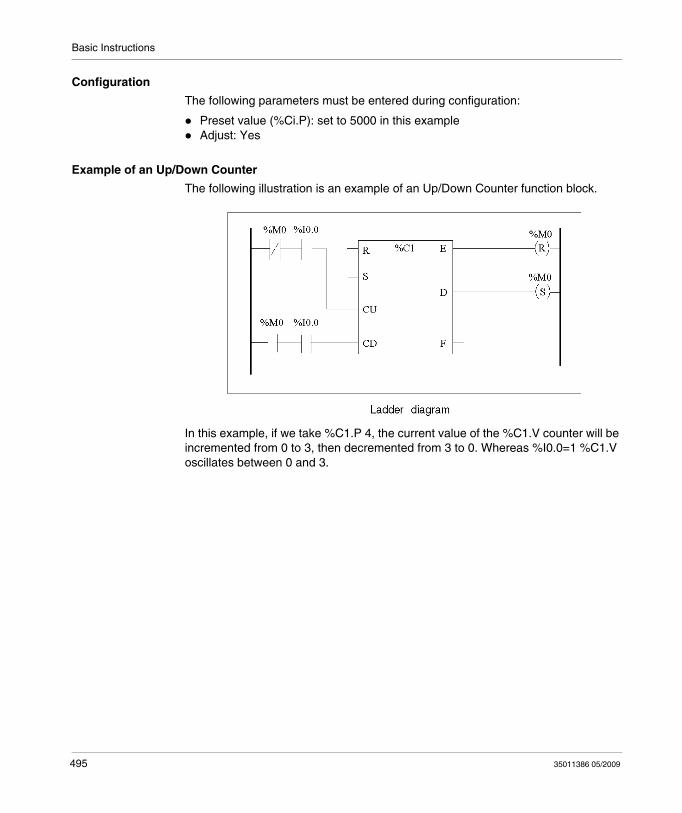
Basic Instructions
Configuration
The following parameters must be entered during configuration:
Preset value (%Ci.P): set to 5000 in this exampleAdjust: Yes
Example of an Up/Down Counter
The following illustration is an example of an Up/Down Counter function block.
In this example, if we take %C1.P 4, the current value of the %C1.V counter will be incremented from 0 to 3, then decremented from 3 to 0. Whereas %I0.0=1 %C1.V oscillates between 0 and 3.
495 35011386 05/2009
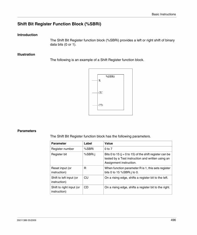
Basic Instructions
Shift Bit Register Function Block (%SBRi)
Introduction
The Shift Bit Register function block (%SBRi) provides a left or right shift of binary data bits (0 or 1).
Illustration
The following is an example of a Shift Register function block.
Parameters
The Shift Bit Register function block has the following parameters.
Parameter Label Value
Register number %SBRi 0 to 7
Register bit %SBRi.j Bits 0 to 15 (j = 0 to 15) of the shift register can be tested by a Test instruction and written using an Assignment instruction.
Reset input (or instruction)
R When function parameter R is 1, this sets register bits 0 to 15 %SBRi.j to 0.
Shift to left input (or instruction)
CU On a rising edge, shifts a register bit to the left.
Shift to right input (or instruction)
CD On a rising edge, shifts a register bit to the right.
35011386 05/2009 496
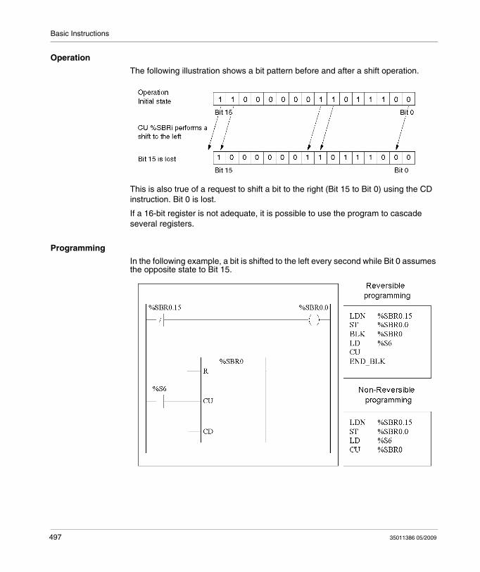
Basic Instructions
Operation
The following illustration shows a bit pattern before and after a shift operation.
This is also true of a request to shift a bit to the right (Bit 15 to Bit 0) using the CD instruction. Bit 0 is lost.
If a 16-bit register is not adequate, it is possible to use the program to cascade several registers.
Programming
In the following example, a bit is shifted to the left every second while Bit 0 assumes the opposite state to Bit 15.
497 35011386 05/2009

Basic Instructions
Special Cases
The following table contains a list of special cases for programming the Shift Bit Register function block.
Special Case Description
Effect of a cold restart (%S0=1) Sets all the bits of the register word to 0.
Effect of a warm restart (%S1=1) Has no effect on the bits of the register word.
35011386 05/2009 498
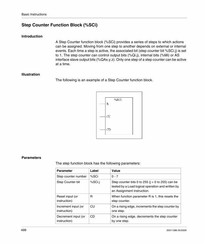
Basic Instructions
Step Counter Function Block (%SCi)
Introduction
A Step Counter function block (%SCi) provides a series of steps to which actions can be assigned. Moving from one step to another depends on external or internal events. Each time a step is active, the associated bit (step counter bit %SCi.j) is set to 1. The step counter can control output bits (%Qi.j), internal bits (%Mi) or AS interface slave output bits (%QAx.y.z). Only one step of a step counter can be active at a time.
Illustration
The following is an example of a Step Counter function block.
Parameters
The step function block has the following parameters:
Parameter Label Value
Step counter number %SCi 0 - 7
Step Counter bit %SCi.j Step counter bits 0 to 255 (j = 0 to 255) can be tested by a Load logical operation and written by an Assignment instruction.
Reset input (or instruction)
R When function parameter R is 1, this resets the step counter.
Increment input (or instruction)
CU On a rising edge, increments the step counter by one step.
Decrement input (or instruction)
CD On a rising edge, decrements the step counter by one step.
499 35011386 05/2009
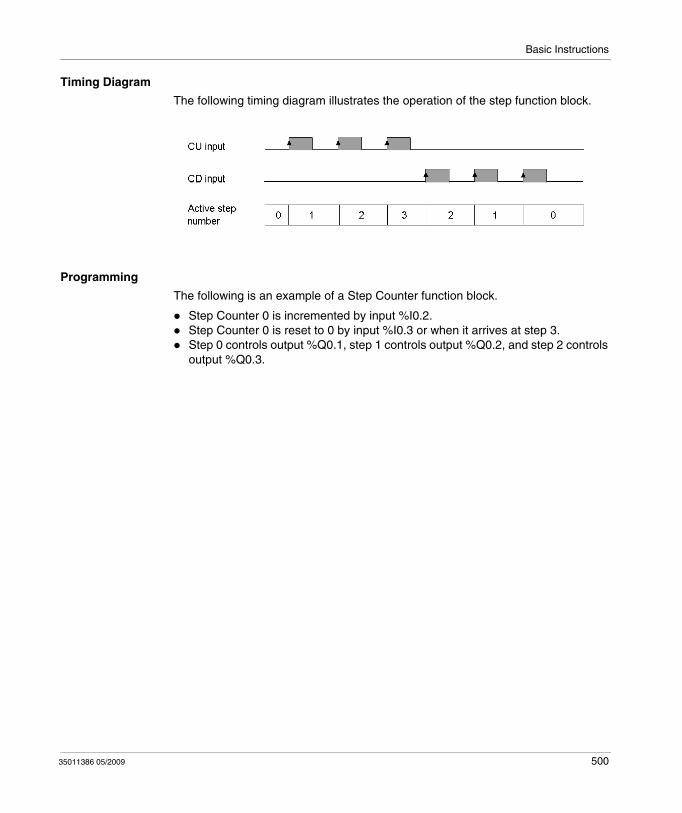
Basic Instructions
Timing Diagram
The following timing diagram illustrates the operation of the step function block.
Programming
The following is an example of a Step Counter function block.
Step Counter 0 is incremented by input %I0.2.Step Counter 0 is reset to 0 by input %I0.3 or when it arrives at step 3.Step 0 controls output %Q0.1, step 1 controls output %Q0.2, and step 2 controls output %Q0.3.
35011386 05/2009 500
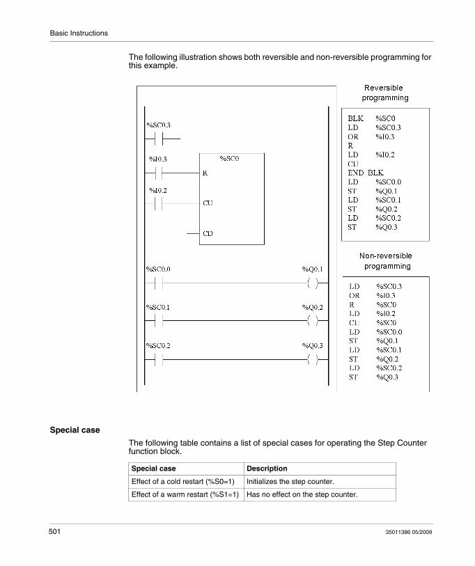
Basic Instructions
The following illustration shows both reversible and non-reversible programming for this example.
Special case
The following table contains a list of special cases for operating the Step Counter function block.
Special case Description
Effect of a cold restart (%S0=1) Initializes the step counter.
Effect of a warm restart (%S1=1) Has no effect on the step counter.
501 35011386 05/2009
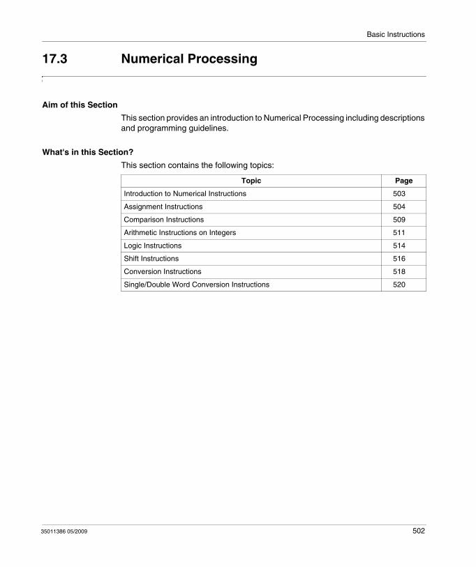
Basic Instructions
17.3 Numerical Processing
Aim of this Section
This section provides an introduction to Numerical Processing including descriptions and programming guidelines.
What's in this Section?
This section contains the following topics:
Topic Page
Introduction to Numerical Instructions 503
Assignment Instructions 504
Comparison Instructions 509
Arithmetic Instructions on Integers 511
Logic Instructions 514
Shift Instructions 516
Conversion Instructions 518
Single/Double Word Conversion Instructions 520
35011386 05/2009 502
Basic Instructions
Introduction to Numerical Instructions
At a Glance
Numerical instructions generally apply to 16-bit words (see Word Objects, page 27) and to 32-bit double words (see page 30). They are written between square brackets. If the result of the preceding logical operation was true (Boolean accumulator = 1), the numerical instruction is executed. If the result of the preceding logical operation was false (Boolean accumulator = 0), the numerical instruction is not executed and the operand remains unchanged.
503 35011386 05/2009
Basic Instructions
Assignment Instructions
Introduction
Assignment instructions are used to load Operand Op2 into Operand Op1.
Assignment
Syntax for Assignment instructions.
Assignment operations can be performed on:Bit stringsWordsDouble wordsFloating wordWord tablesDouble word tablesFloating word tables
Assignment of Bit Strings
Operations can be performed on the following bit strings (see Structured Objects, page 44):
Bit string -> bit string (Example 1)Bit string -> word (Example 2) or double word (indexed)Word or double word (indexed) -> bit string (Example 3)Immediate value -> bit string
35011386 05/2009 504
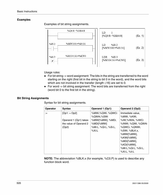
Basic Instructions
Examples
Examples of bit string assignments.
Usage rules:For bit string -> word assignment: The bits in the string are transferred to the word starting on the right (first bit in the string to bit 0 in the word), and the word bits which are not involved in the transfer (length ≤16) are set to 0.For word -> bit string assignment: The word bits are transferred from the right (word bit 0 to the first bit in the string).
Bit String Assignments
Syntax for bit string assignments.
NOTE: The abbreviation %BLK.x (for example, %C0.P) is used to describe any function block word.
Operator Syntax Operand 1 (Op1) Operand 2 (Op2)
:= [Op1: = Op2]
Operand 1 (Op1) takes the value of Operand 2 (Op2)
%MWi,%QWi, %QWCi %QWAi,%SWi %MWi[%MWi], %MDi, %MDi[%MWi]%Mi:L, %Qi:L, %Si:L, %Xi:L
Immediate value, %MWi, %KWi, %IW,%IWAi, %IWCi %INWi, %QWi, %QWAi %QWCi, %QNWi, %SWi, %BLK.x, %MWi[%MWi], %KWi[%MWi], %MDi[%MWi], %KDi[%MWi], %Mi:L,%Qi:L, %Si:L, %Xi:L, %Ii:L
505 35011386 05/2009
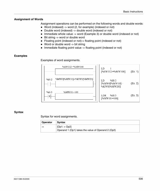
Basic Instructions
Assignment of Words
Assignment operations can be performed on the following words and double words:Word (indexed) -> word (2, for example) (indexed or not)Double word (indexed) -> double word (indexed or not)Immediate whole value -> word (Example 3) or double word (indexed or not)Bit string -> word or double wordFloating point (indexed or not)-> floating point (indexed or not)Word or double word -> bit stringImmediate floating point value -> floating point (indexed or not)
Examples
Examples of word assignments.
Syntax
Syntax for word assignments.
Operator Syntax
:= [Op1: = Op2] Operand 1 (Op1) takes the value of Operand 2 (Op2)
35011386 05/2009 506

Basic Instructions
The following table gives details operands:
NOTE: The abbreviation %BLK.x (for example, R3.I) is used to describe any function block word. For bit strings %Mi:L, %Si:L, and %Xi:L, the base address of the first of the bit string must be a multiple of 8 (0, 8, 16, ..., 96, ...).
Assignment of Word, Double Word and Floating Point Tables
Assignment operations can be performed on the following object tables (see Tables of words, page 45):
Immediate whole value -> word table (Example 1) or double word tableWord -> word table (Example 2)Word table -> word table (Example 3)Table length (L) should be the same for both tables.Double word -> double word tableDouble word table -> double word tableTable length (L) should be the same for both tables.Immediate floating point value -> floating point tableFloating point -> floating point tableFloating point table-> floating point tableTable length (L) should be the same for both tables.
Type Operand 1 (Op1) Operand 2 (Op2)
word, double word, bit string
%BLK.x, %MWi, %QWi, %QWAi, %QWCi, %SWi %MWi[MWi], %MDi, %MDi[%MWj], %Mi:L, %Qi:L, %Si:L, %Xi:L
Immediate value, %MWi, %KWi, %IW, %IWAi, %IWCi, %QWi, %QWAi,%QWCi, %SWi, %MWi[MWi], %KWi[MWi], %MDi, %MDi[%MWj], %KDi, %KDi[MWj] %INW, %Mi:L, %Qi:L, %QNW, %Si:L, %Xi:L, %Ii:L
Floating point
%MFi, %MFi[%MWj] Immediate floating point value, %MFi, %MFi[%MWj], %KFi, %KFi[%MWj]
507 35011386 05/2009
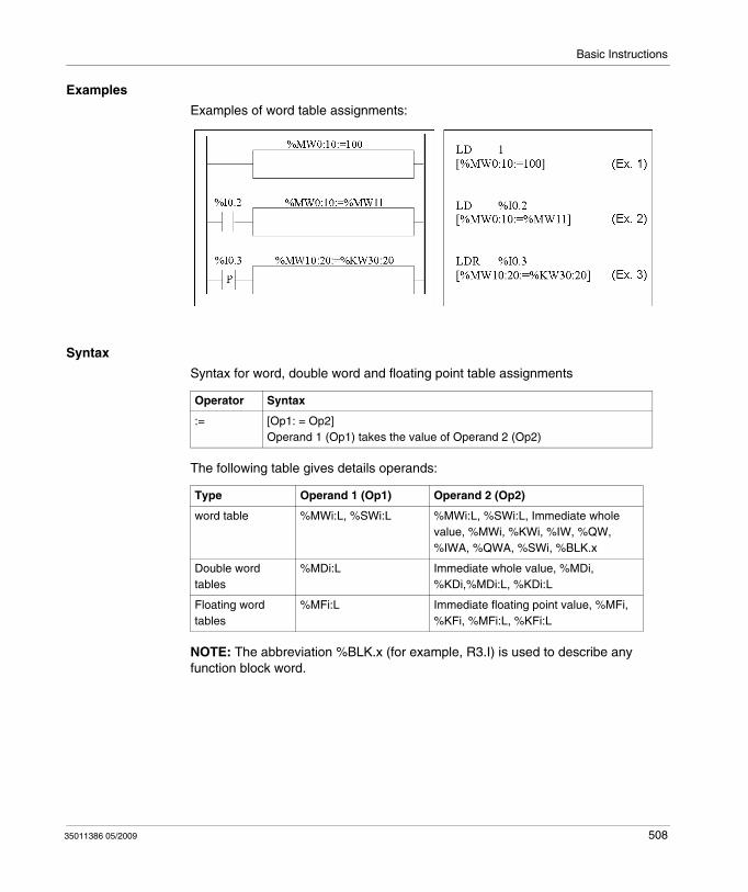
Basic Instructions
Examples
Examples of word table assignments:
Syntax
Syntax for word, double word and floating point table assignments
The following table gives details operands:
NOTE: The abbreviation %BLK.x (for example, R3.I) is used to describe any function block word.
Operator Syntax
:= [Op1: = Op2] Operand 1 (Op1) takes the value of Operand 2 (Op2)
Type Operand 1 (Op1) Operand 2 (Op2)
word table %MWi:L, %SWi:L %MWi:L, %SWi:L, Immediate whole value, %MWi, %KWi, %IW, %QW, %IWA, %QWA, %SWi, %BLK.x
Double word tables
%MDi:L Immediate whole value, %MDi, %KDi,%MDi:L, %KDi:L
Floating word tables
%MFi:L Immediate floating point value, %MFi, %KFi, %MFi:L, %KFi:L
35011386 05/2009 508
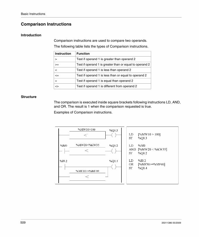
Basic Instructions
Comparison Instructions
Introduction
Comparison instructions are used to compare two operands.
The following table lists the types of Comparison instructions.
Structure
The comparison is executed inside square brackets following instructions LD, AND, and OR. The result is 1 when the comparison requested is true.
Examples of Comparison instructions.
Instruction Function
> Test if operand 1 is greater than operand 2
>= Test if operand 1 is greater than or equal to operand 2
< Test if operand 1 is less than operand 2
<= Test if operand 1 is less than or equal to operand 2
= Test if operand 1 is equal than operand 2
<> Test if operand 1 is different from operand 2
509 35011386 05/2009
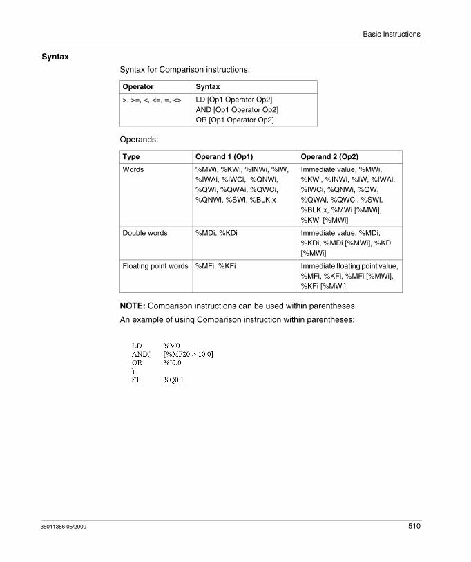
Basic Instructions
Syntax
Syntax for Comparison instructions:
Operands:
NOTE: Comparison instructions can be used within parentheses.
An example of using Comparison instruction within parentheses:
Operator Syntax
>, >=, <, <=, =, <> LD [Op1 Operator Op2]AND [Op1 Operator Op2]OR [Op1 Operator Op2]
Type Operand 1 (Op1) Operand 2 (Op2)
Words %MWi, %KWi, %INWi, %IW, %IWAi, %IWCi, %QNWi, %QWi, %QWAi, %QWCi, %QNWi, %SWi, %BLK.x
Immediate value, %MWi, %KWi, %INWi, %IW, %IWAi, %IWCi, %QNWi, %QW, %QWAi, %QWCi, %SWi, %BLK.x, %MWi [%MWi], %KWi [%MWi]
Double words %MDi, %KDi Immediate value, %MDi, %KDi, %MDi [%MWi], %KD [%MWi]
Floating point words %MFi, %KFi Immediate floating point value, %MFi, %KFi, %MFi [%MWi], %KFi [%MWi]
35011386 05/2009 510
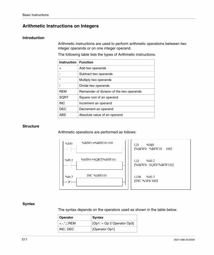
Basic Instructions
Arithmetic Instructions on Integers
Introduction
Arithmetic instructions are used to perform arithmetic operations between two integer operands or on one integer operand.
The following table lists the types of Arithmetic instructions.
Structure
Arithmetic operations are performed as follows:
Syntax
The syntax depends on the operators used as shown in the table below.
Instruction Function
+ Add two operands
- Subtract two operands
* Multiply two operands
/ Divide two operands
REM Remainder of division of the two operands
SQRT Square root of an operand
INC Increment an operand
DEC Decrement an operand
ABS Absolute value of an operand
Operator Syntax
+,-,*,/,REM [Op1: = Op 2 Operator Op3]
INC, DEC [Operator Op1]
511 35011386 05/2009
Basic Instructions
Operands:
NOTE: (1) With this operator, Op2 cannot be an immediate value.
The ABS function can only be used with double words (%MD and %KD) and floating points (%MF and %KF). Consequently, OP1 and OP2 must be double words or floating points.
Overflow and Error Conditions
AdditionOverflow during word operationIf the result exceeds the capacity of the result word, bit %S18 (overflow) is set to 1 and the result is not significant (see Example 1, next page). The user program manages bit %S18.
Note:
For double words, the limits are -2147483648 and 2147483647.
MultiplicationOverflow during operationIf the result exceeds the capacity of the result word, bit %S18 (overflow) is set to 1 and the result is not significant.
Division / remainderDivision by 0If the divider is 0, the division is impossible and system bit %S18 is set to 1. The result is then incorrect.Overflow during operationIf the division quotient exceeds the capacity of the result word, bit %S18 is set to 1.
SQRT (1) [Op1: = SQRT(Op2)]
ABS (1) [Op1: = ABS(Op2)]
Type Operand 1 (Op1) Operands 2 and 3 (Op2 & 3) (1)
Words %MWi, %QWi, %QWAi, %QWCi, %SWi
Immediate value, %MWi, %KWi, %INW, %IW, %IWAi, %IWCi, %QNW, %QW, %QWAi, %QWCi, %SWi, %BLK.x
Double words %MDi Immediate value, %MDi, %KDi
Operator Syntax
35011386 05/2009 512
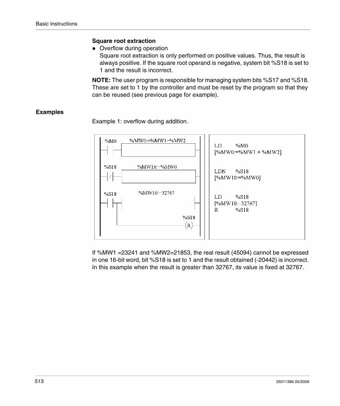
Basic Instructions
Square root extractionOverflow during operationSquare root extraction is only performed on positive values. Thus, the result is always positive. If the square root operand is negative, system bit %S18 is set to 1 and the result is incorrect.
NOTE: The user program is responsible for managing system bits %S17 and %S18. These are set to 1 by the controller and must be reset by the program so that they can be reused (see previous page for example).
Examples
Example 1: overflow during addition.
If %MW1 =23241 and %MW2=21853, the real result (45094) cannot be expressed in one 16-bit word, bit %S18 is set to 1 and the result obtained (-20442) is incorrect. In this example when the result is greater than 32767, its value is fixed at 32767.
513 35011386 05/2009
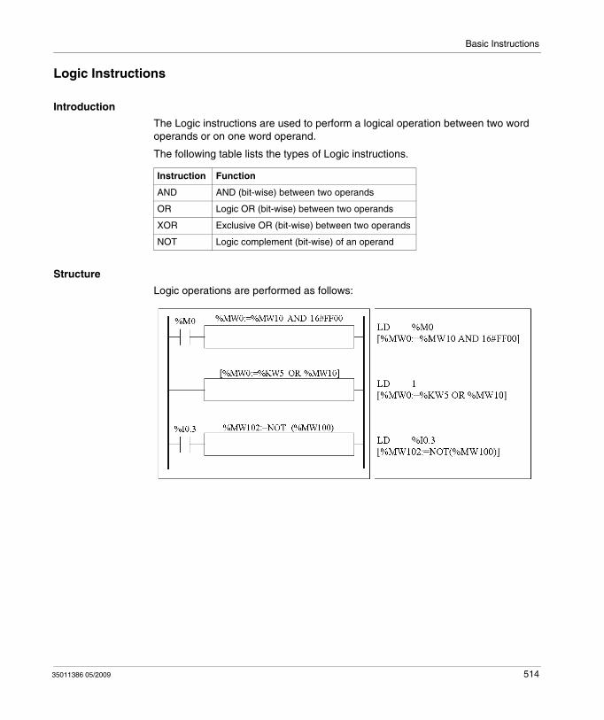
Basic Instructions
Logic Instructions
Introduction
The Logic instructions are used to perform a logical operation between two word operands or on one word operand.
The following table lists the types of Logic instructions.
Structure
Logic operations are performed as follows:
Instruction Function
AND AND (bit-wise) between two operands
OR Logic OR (bit-wise) between two operands
XOR Exclusive OR (bit-wise) between two operands
NOT Logic complement (bit-wise) of an operand
35011386 05/2009 514
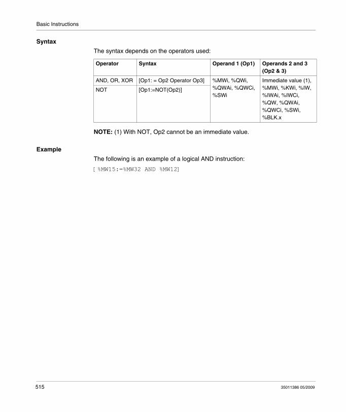
Basic Instructions
Syntax
The syntax depends on the operators used:
NOTE: (1) With NOT, Op2 cannot be an immediate value.
Example
The following is an example of a logical AND instruction:
[%MW15:=%MW32 AND %MW12]
Operator Syntax Operand 1 (Op1) Operands 2 and 3 (Op2 & 3)
AND, OR, XOR [Op1: = Op2 Operator Op3] %MWi, %QWi, %QWAi, %QWCi, %SWi
Immediate value (1), %MWi, %KWi, %IW, %IWAi, %IWCi, %QW, %QWAi, %QWCi, %SWi, %BLK.x
NOT [Op1:=NOT(Op2)]
515 35011386 05/2009
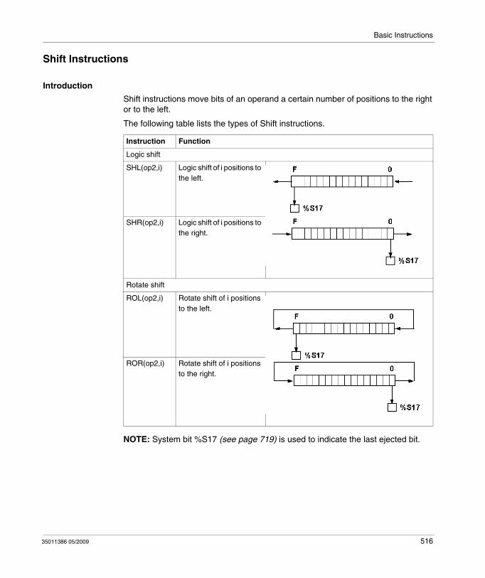
Basic Instructions
Shift Instructions
Introduction
Shift instructions move bits of an operand a certain number of positions to the right or to the left.
The following table lists the types of Shift instructions.
NOTE: System bit %S17 (see page 719) is used to indicate the last ejected bit.
Instruction Function
Logic shift
SHL(op2,i) Logic shift of i positions to the left.
SHR(op2,i) Logic shift of i positions to the right.
Rotate shift
ROL(op2,i) Rotate shift of i positions to the left.
ROR(op2,i) Rotate shift of i positions to the right.
35011386 05/2009 516
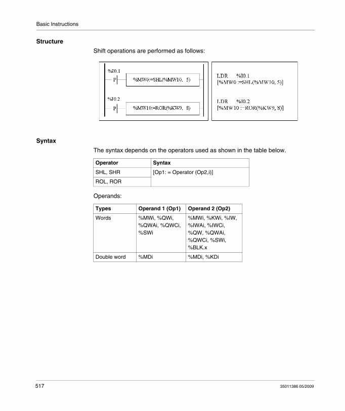
Basic Instructions
Structure
Shift operations are performed as follows:
Syntax
The syntax depends on the operators used as shown in the table below.
Operands:
Operator Syntax
SHL, SHR [Op1: = Operator (Op2,i)]
ROL, ROR
Types Operand 1 (Op1) Operand 2 (Op2)
Words %MWi, %QWi, %QWAi, %QWCi, %SWi
%MWi, %KWi, %IW, %IWAi, %IWCi, %QW, %QWAi, %QWCi, %SWi, %BLK.x
Double word %MDi %MDi, %KDi
517 35011386 05/2009
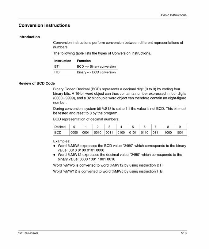
Basic Instructions
Conversion Instructions
Introduction
Conversion instructions perform conversion between different representations of numbers.
The following table lists the types of Conversion instructions.
Review of BCD Code
Binary Coded Decimal (BCD) represents a decimal digit (0 to 9) by coding four binary bits. A 16-bit word object can thus contain a number expressed in four digits (0000 - 9999), and a 32 bit double word object can therefore contain an eight-figure number.
During conversion, system bit %S18 is set to 1 if the value is not BCD. This bit must be tested and reset to 0 by the program.
BCD representation of decimal numbers:
Examples:Word %MW5 expresses the BCD value "2450" which corresponds to the binary value: 0010 0100 0101 0000Word %MW12 expresses the decimal value "2450" which corresponds to the binary value: 0000 1001 1001 0010
Word %MW5 is converted to word %MW12 by using instruction BTI.
Word %MW12 is converted to word %MW5 by using instruction ITB.
Instruction Function
BTI BCD --> Binary conversion
ITB Binary --> BCD conversion
Decimal 0 1 2 3 4 5 6 7 8 9
BCD 0000 0001 0010 0011 0100 0101 0110 0111 1000 1001
35011386 05/2009 518
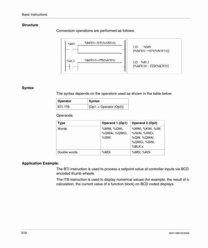
Basic Instructions
Structure
Conversion operations are performed as follows:
Syntax
The syntax depends on the operators used as shown in the table below.
Operands:
Application Example:
The BTI instruction is used to process a setpoint value at controller inputs via BCD encoded thumb wheels.
The ITB instruction is used to display numerical values (for example, the result of a calculation, the current value of a function block) on BCD coded displays.
Operator Syntax
BTI, ITB [Op1: = Operator (Op2)]
Type Operand 1 (Op1) Operand 2 (Op2)
Words %MWi, %QWi, %QWAi, %QWCi, %SWi
%MWi, %KWi, %IW, %IWAi, %IWCi, %QW, %QWAi, %QWCi, %SWi, %BLK.x
Double words %MDi %MDi, %KDi
519 35011386 05/2009
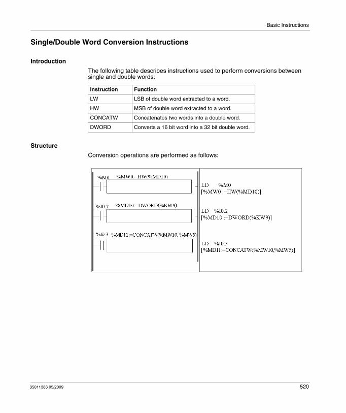
Basic Instructions
Single/Double Word Conversion Instructions
Introduction
The following table describes instructions used to perform conversions between single and double words:
Structure
Conversion operations are performed as follows:
Instruction Function
LW LSB of double word extracted to a word.
HW MSB of double word extracted to a word.
CONCATW Concatenates two words into a double word.
DWORD Converts a 16 bit word into a 32 bit double word.
35011386 05/2009 520
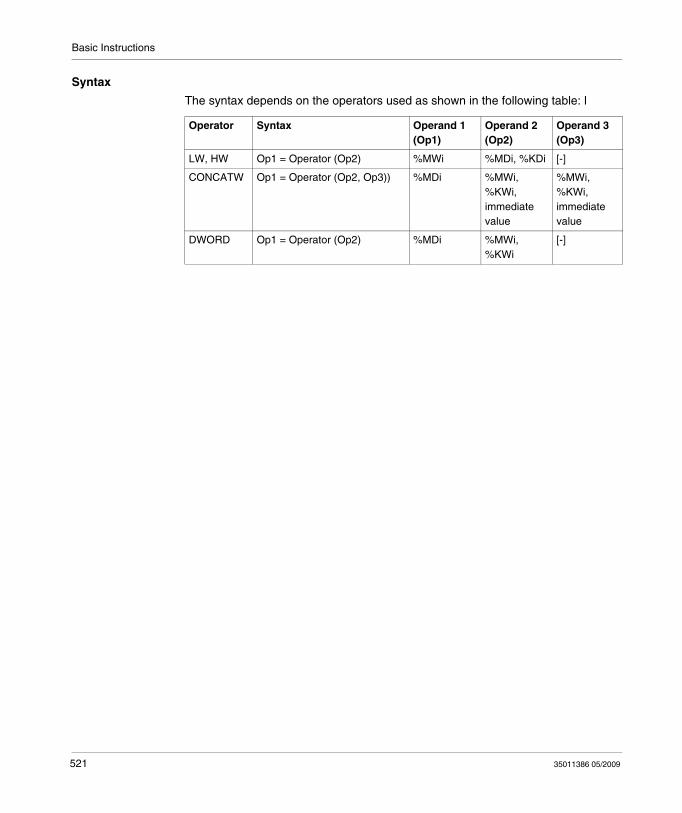
Basic Instructions
Syntax
The syntax depends on the operators used as shown in the following table: l
Operator Syntax Operand 1 (Op1)
Operand 2 (Op2)
Operand 3 (Op3)
LW, HW Op1 = Operator (Op2) %MWi %MDi, %KDi [-]
CONCATW Op1 = Operator (Op2, Op3)) %MDi %MWi, %KWi, immediate value
%MWi, %KWi, immediate value
DWORD Op1 = Operator (Op2) %MDi %MWi, %KWi
[-]
521 35011386 05/2009
Basic Instructions
17.4 Program Instructions
Aim of this Section
This section provides an introduction to Program Instructions.
What's in this Section?
This section contains the following topics:
Topic Page
END Instructions 523
NOP Instruction 525
Jump Instructions 526
Subroutine Instructions 528
35011386 05/2009 522
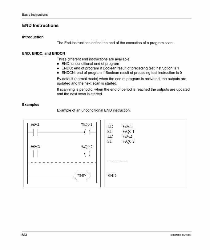
Basic Instructions
END Instructions
Introduction
The End instructions define the end of the execution of a program scan.
END, ENDC, and ENDCN
Three different end instructions are available:END: unconditional end of programENDC: end of program if Boolean result of preceding test instruction is 1ENDCN: end of program if Boolean result of preceding test instruction is 0
By default (normal mode) when the end of program is activated, the outputs are updated and the next scan is started.
If scanning is periodic, when the end of period is reached the outputs are updated and the next scan is started.
Examples
Example of an unconditional END instruction.
523 35011386 05/2009
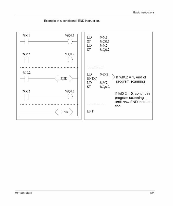
Basic Instructions
Example of a conditional END instruction.
35011386 05/2009 524

Basic Instructions
NOP Instruction
NOP
The NOP instruction does not perform any operation. Use it to "reserve" lines in a program so that you can insert instructions later without modifying the line numbers.
525 35011386 05/2009
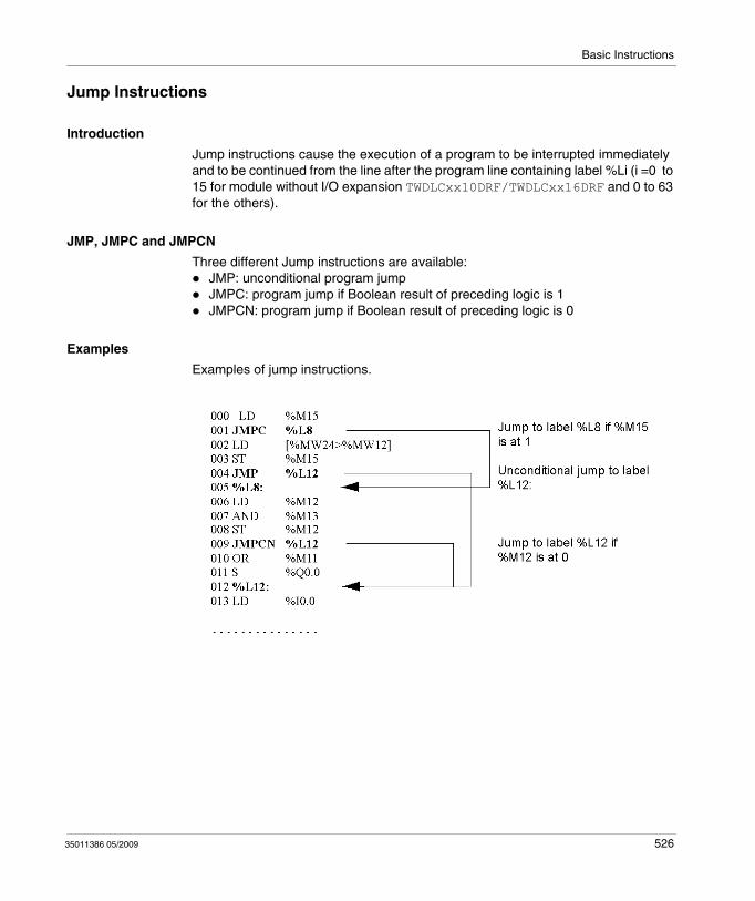
Basic Instructions
Jump Instructions
Introduction
Jump instructions cause the execution of a program to be interrupted immediately and to be continued from the line after the program line containing label %Li (i =0 to 15 for module without I/O expansion TWDLCxx10DRF/TWDLCxx16DRF and 0 to 63 for the others).
JMP, JMPC and JMPCN
Three different Jump instructions are available:JMP: unconditional program jumpJMPC: program jump if Boolean result of preceding logic is 1JMPCN: program jump if Boolean result of preceding logic is 0
Examples
Examples of jump instructions.
35011386 05/2009 526

Basic Instructions
Guidelines
Jump instructions are not permitted between parentheses, and must not be placed between the instructions AND(, OR(and a close parenthesis instruction ")". The label can only be placed before a LD, LDN, LDR, LDF or BLK instruction.The label number of label %Li must be defined only once in a program.The program jump is performed to a line of programming which is downstream or upstream. When the jump is upstream, attention must be paid to the program scan time. Extended scan time can cause triggering of the watchdog.
527 35011386 05/2009
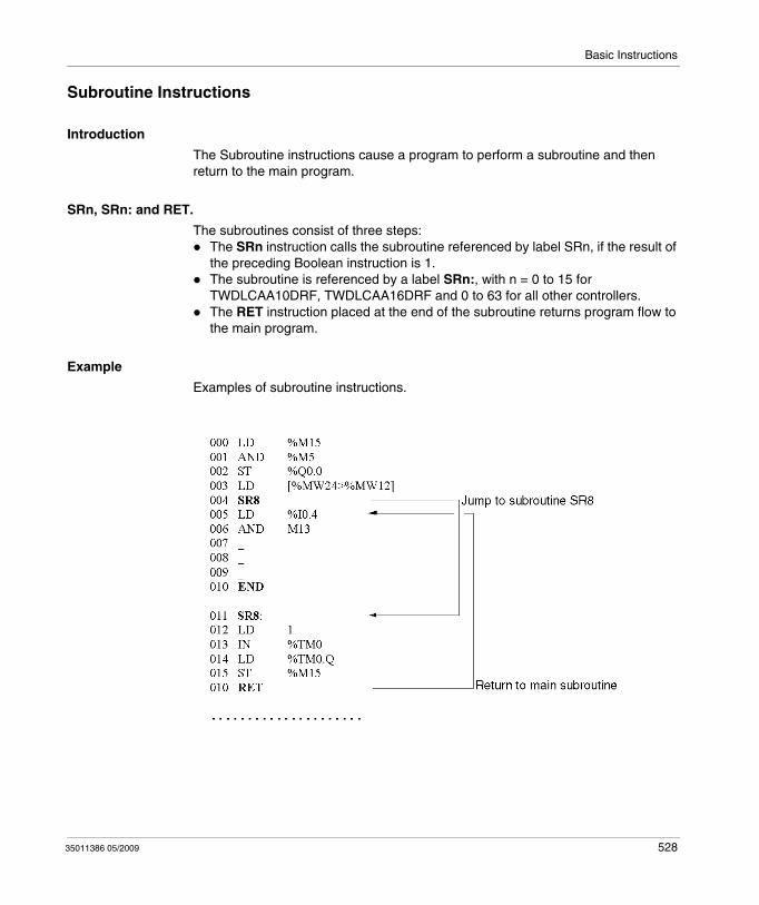
Basic Instructions
Subroutine Instructions
Introduction
The Subroutine instructions cause a program to perform a subroutine and then return to the main program.
SRn, SRn: and RET.
The subroutines consist of three steps:The SRn instruction calls the subroutine referenced by label SRn, if the result of the preceding Boolean instruction is 1.The subroutine is referenced by a label SRn:, with n = 0 to 15 for TWDLCAA10DRF, TWDLCAA16DRF and 0 to 63 for all other controllers.The RET instruction placed at the end of the subroutine returns program flow to the main program.
Example
Examples of subroutine instructions.
35011386 05/2009 528
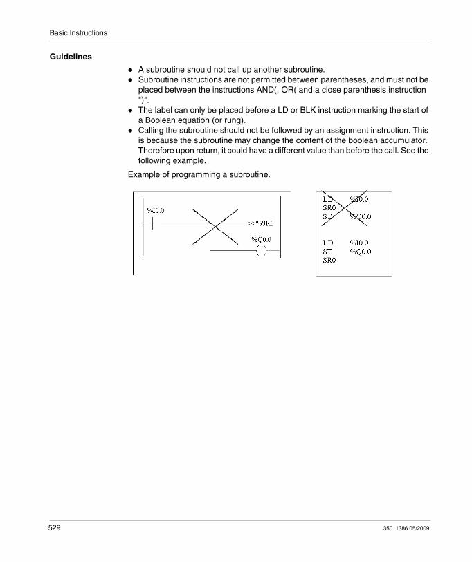
Basic Instructions
Guidelines
A subroutine should not call up another subroutine.Subroutine instructions are not permitted between parentheses, and must not be placed between the instructions AND(, OR( and a close parenthesis instruction ")".The label can only be placed before a LD or BLK instruction marking the start of a Boolean equation (or rung).Calling the subroutine should not be followed by an assignment instruction. This is because the subroutine may change the content of the boolean accumulator. Therefore upon return, it could have a different value than before the call. See the following example.
Example of programming a subroutine.
529 35011386 05/2009
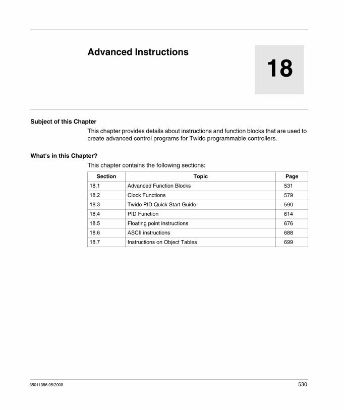
35011386 05/2009
18
Advanced Instructions
35011386 05/2009
Advanced Instructions
Subject of this Chapter
This chapter provides details about instructions and function blocks that are used to create advanced control programs for Twido programmable controllers.
What's in this Chapter?
This chapter contains the following sections:
Section Topic Page
18.1 Advanced Function Blocks 531
18.2 Clock Functions 579
18.3 Twido PID Quick Start Guide 590
18.4 PID Function 614
18.5 Floating point instructions 676
18.6 ASCII instructions 688
18.7 Instructions on Object Tables 699
530
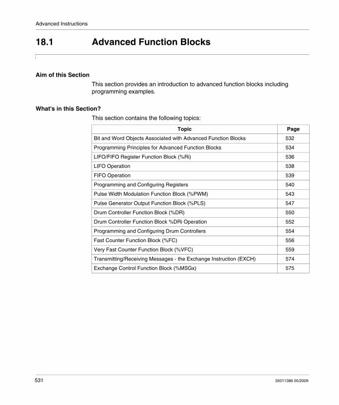
Advanced Instructions
18.1 Advanced Function Blocks
Aim of this Section
This section provides an introduction to advanced function blocks including programming examples.
What's in this Section?
This section contains the following topics:
Topic Page
Bit and Word Objects Associated with Advanced Function Blocks 532
Programming Principles for Advanced Function Blocks 534
LIFO/FIFO Register Function Block (%Ri) 536
LIFO Operation 538
FIFO Operation 539
Programming and Configuring Registers 540
Pulse Width Modulation Function Block (%PWM) 543
Pulse Generator Output Function Block (%PLS) 547
Drum Controller Function Block (%DR) 550
Drum Controller Function Block %DRi Operation 552
Programming and Configuring Drum Controllers 554
Fast Counter Function Block (%FC) 556
Very Fast Counter Function Block (%VFC) 559
Transmitting/Receiving Messages - the Exchange Instruction (EXCH) 574
Exchange Control Function Block (%MSGx) 575
531 35011386 05/2009
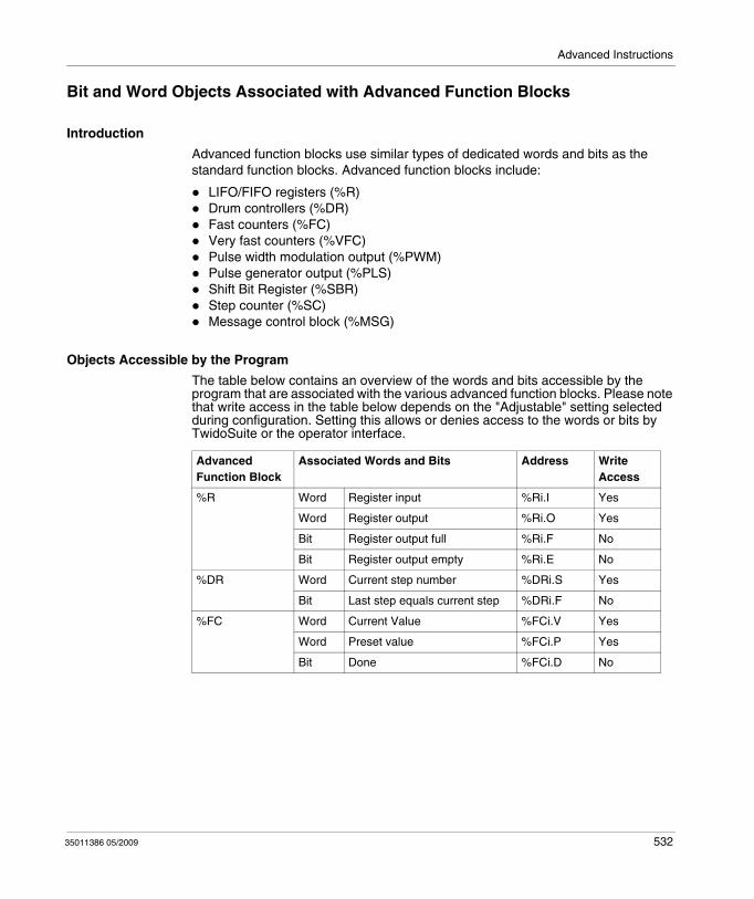
Advanced Instructions
Bit and Word Objects Associated with Advanced Function Blocks
Introduction
Advanced function blocks use similar types of dedicated words and bits as the standard function blocks. Advanced function blocks include:
LIFO/FIFO registers (%R)Drum controllers (%DR)Fast counters (%FC)Very fast counters (%VFC)Pulse width modulation output (%PWM)Pulse generator output (%PLS)Shift Bit Register (%SBR)Step counter (%SC)Message control block (%MSG)
Objects Accessible by the Program
The table below contains an overview of the words and bits accessible by the program that are associated with the various advanced function blocks. Please note that write access in the table below depends on the "Adjustable" setting selected during configuration. Setting this allows or denies access to the words or bits by TwidoSuite or the operator interface.
Advanced Function Block
Associated Words and Bits Address Write Access
%R Word Register input %Ri.I Yes
Word Register output %Ri.O Yes
Bit Register output full %Ri.F No
Bit Register output empty %Ri.E No
%DR Word Current step number %DRi.S Yes
Bit Last step equals current step %DRi.F No
%FC Word Current Value %FCi.V Yes
Word Preset value %FCi.P Yes
Bit Done %FCi.D No
35011386 05/2009 532
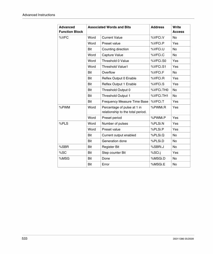
Advanced Instructions
%VFC Word Current Value %VFCi.V No
Word Preset value %VFCi.P Yes
Bit Counting direction %VFCi.U No
Word Capture Value %VFCi.C No
Word Threshold 0 Value %VFCi.S0 Yes
Word Threshold Value1 %VFCi.S1 Yes
Bit Overflow %VFCi.F No
Bit Reflex Output 0 Enable %VFCi.R Yes
Bit Reflex Output 1 Enable %VFCi.S Yes
Bit Threshold Output 0 %VFCi.TH0 No
Bit Threshold Output 1 %VFCi.TH1 No
Bit Frequency Measure Time Base %VFCi.T Yes
%PWM Word Percentage of pulse at 1 in relationship to the total period.
%PWMi.R Yes
Word Preset period %PWMi.P Yes
%PLS Word Number of pulses %PLSi.N Yes
Word Preset value %PLSi.P Yes
Bit Current output enabled %PLSi.Q No
Bit Generation done %PLSi.D No
%SBR Bit Register Bit %SBRi.J No
%SC Bit Step counter Bit %SCi.j Yes
%MSG Bit Done %MSGi.D No
Bit Error %MSGi.E No
Advanced Function Block
Associated Words and Bits Address Write Access
533 35011386 05/2009
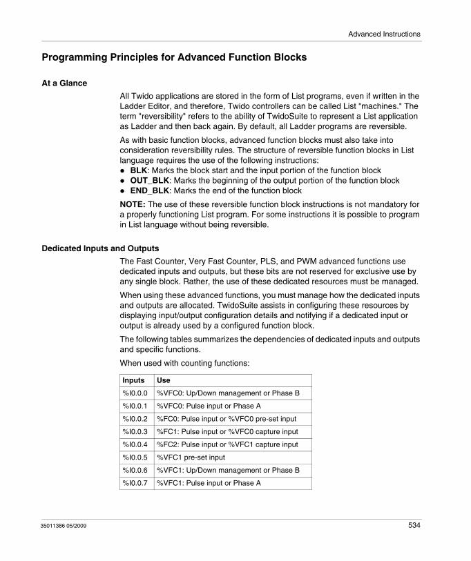
Advanced Instructions
Programming Principles for Advanced Function Blocks
At a Glance
All Twido applications are stored in the form of List programs, even if written in the Ladder Editor, and therefore, Twido controllers can be called List "machines." The term "reversibility" refers to the ability of TwidoSuite to represent a List application as Ladder and then back again. By default, all Ladder programs are reversible.
As with basic function blocks, advanced function blocks must also take into consideration reversibility rules. The structure of reversible function blocks in List language requires the use of the following instructions:
BLK: Marks the block start and the input portion of the function blockOUT_BLK: Marks the beginning of the output portion of the function blockEND_BLK: Marks the end of the function block
NOTE: The use of these reversible function block instructions is not mandatory for a properly functioning List program. For some instructions it is possible to program in List language without being reversible.
Dedicated Inputs and Outputs
The Fast Counter, Very Fast Counter, PLS, and PWM advanced functions use dedicated inputs and outputs, but these bits are not reserved for exclusive use by any single block. Rather, the use of these dedicated resources must be managed.
When using these advanced functions, you must manage how the dedicated inputs and outputs are allocated. TwidoSuite assists in configuring these resources by displaying input/output configuration details and notifying if a dedicated input or output is already used by a configured function block.
The following tables summarizes the dependencies of dedicated inputs and outputs and specific functions.
When used with counting functions:
Inputs Use
%I0.0.0 %VFC0: Up/Down management or Phase B
%I0.0.1 %VFC0: Pulse input or Phase A
%I0.0.2 %FC0: Pulse input or %VFC0 pre-set input
%I0.0.3 %FC1: Pulse input or %VFC0 capture input
%I0.0.4 %FC2: Pulse input or %VFC1 capture input
%I0.0.5 %VFC1 pre-set input
%I0.0.6 %VFC1: Up/Down management or Phase B
%I0.0.7 %VFC1: Pulse input or Phase A
35011386 05/2009 534
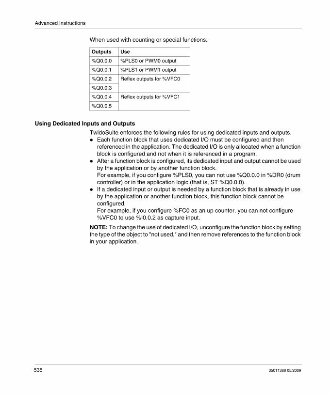
Advanced Instructions
When used with counting or special functions:
Using Dedicated Inputs and Outputs
TwidoSuite enforces the following rules for using dedicated inputs and outputs.Each function block that uses dedicated I/O must be configured and then referenced in the application. The dedicated I/O is only allocated when a function block is configured and not when it is referenced in a program.After a function block is configured, its dedicated input and output cannot be used by the application or by another function block.For example, if you configure %PLS0, you can not use %Q0.0.0 in %DR0 (drum controller) or in the application logic (that is, ST %Q0.0.0).If a dedicated input or output is needed by a function block that is already in use by the application or another function block, this function block cannot be configured.For example, if you configure %FC0 as an up counter, you can not configure %VFC0 to use %I0.0.2 as capture input.
NOTE: To change the use of dedicated I/O, unconfigure the function block by setting the type of the object to "not used," and then remove references to the function block in your application.
Outputs Use
%Q0.0.0 %PLS0 or PWM0 output
%Q0.0.1 %PLS1 or PWM1 output
%Q0.0.2 Reflex outputs for %VFC0
%Q0.0.3
%Q0.0.4 Reflex outputs for %VFC1
%Q0.0.5
535 35011386 05/2009
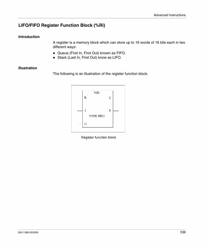
Advanced Instructions
LIFO/FIFO Register Function Block (%Ri)
Introduction
A register is a memory block which can store up to 16 words of 16 bits each in two different ways:
Queue (First In, First Out) known as FIFO.Stack (Last In, First Out) know as LIFO.
Illustration
The following is an illustration of the register function block.
35011386 05/2009 536
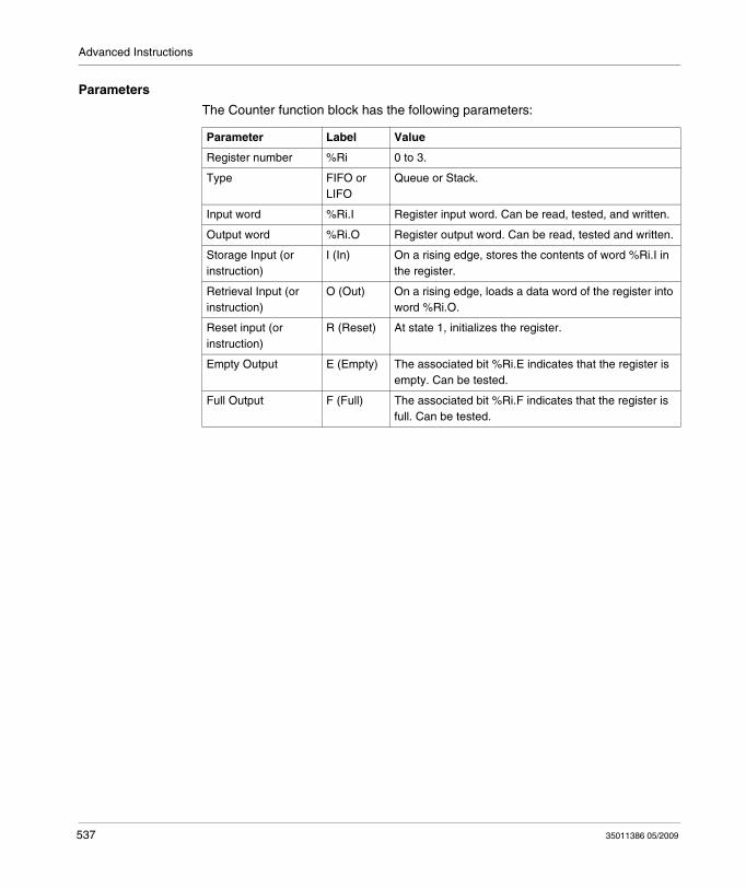
Advanced Instructions
Parameters
The Counter function block has the following parameters:
Parameter Label Value
Register number %Ri 0 to 3.
Type FIFO or LIFO
Queue or Stack.
Input word %Ri.I Register input word. Can be read, tested, and written.
Output word %Ri.O Register output word. Can be read, tested and written.
Storage Input (or instruction)
I (In) On a rising edge, stores the contents of word %Ri.I in the register.
Retrieval Input (or instruction)
O (Out) On a rising edge, loads a data word of the register into word %Ri.O.
Reset input (or instruction)
R (Reset) At state 1, initializes the register.
Empty Output E (Empty) The associated bit %Ri.E indicates that the register is empty. Can be tested.
Full Output F (Full) The associated bit %Ri.F indicates that the register is full. Can be tested.
537 35011386 05/2009
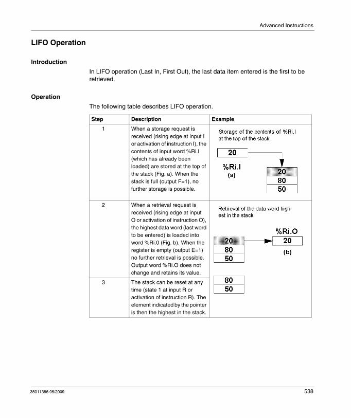
Advanced Instructions
LIFO Operation
Introduction
In LIFO operation (Last In, First Out), the last data item entered is the first to be retrieved.
Operation
The following table describes LIFO operation.
Step Description Example
1 When a storage request is received (rising edge at input I or activation of instruction I), the contents of input word %Ri.I (which has already been loaded) are stored at the top of the stack (Fig. a). When the stack is full (output F=1), no further storage is possible.
2 When a retrieval request is received (rising edge at input O or activation of instruction O), the highest data word (last word to be entered) is loaded into word %Ri.0 (Fig. b). When the register is empty (output E=1) no further retrieval is possible. Output word %Ri.O does not change and retains its value.
3 The stack can be reset at any time (state 1 at input R or activation of instruction R). The element indicated by the pointer is then the highest in the stack.
35011386 05/2009 538
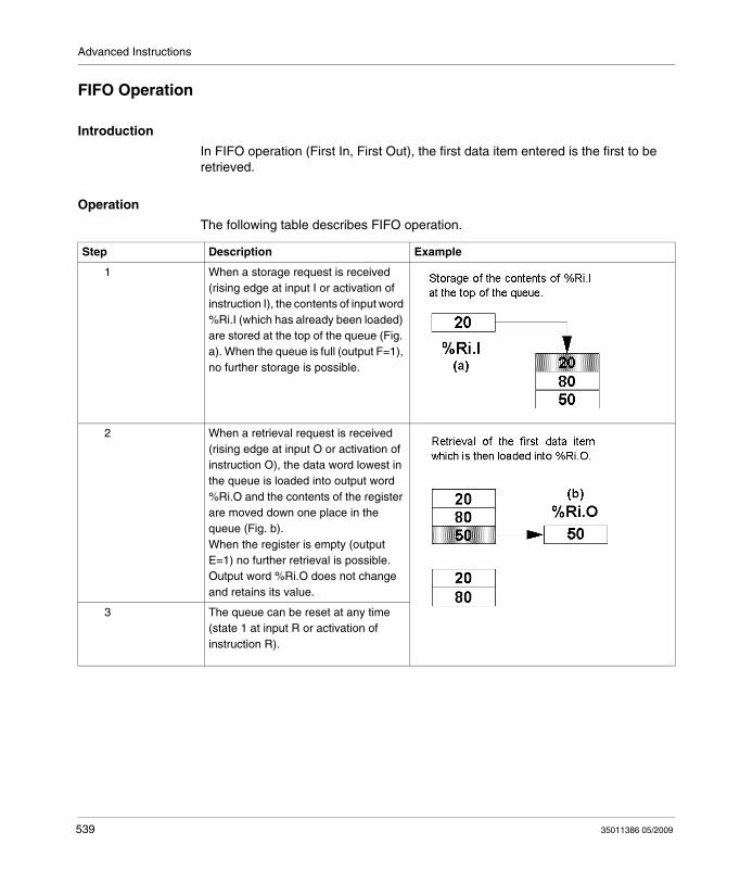
Advanced Instructions
FIFO Operation
Introduction
In FIFO operation (First In, First Out), the first data item entered is the first to be retrieved.
Operation
The following table describes FIFO operation.
Step Description Example
1 When a storage request is received (rising edge at input I or activation of instruction I), the contents of input word %Ri.I (which has already been loaded) are stored at the top of the queue (Fig. a). When the queue is full (output F=1), no further storage is possible.
2 When a retrieval request is received (rising edge at input O or activation of instruction O), the data word lowest in the queue is loaded into output word %Ri.O and the contents of the register are moved down one place in the queue (Fig. b). When the register is empty (output E=1) no further retrieval is possible. Output word %Ri.O does not change and retains its value.
3 The queue can be reset at any time (state 1 at input R or activation of instruction R).
539 35011386 05/2009

Advanced Instructions
Programming and Configuring Registers
Introduction
The following programming example shows the content of a memory word (%MW34) being loaded into a register (%R2.I) on reception of a storage request (%I0.2), if register %R2 is not full (%R2.F = 0). The storage request in the register is made by %M1. The retrieval request is made by input %I0.3, and %R2.O is loaded into %MW20, if the register is not empty (%R2.E = 0).
35011386 05/2009 540
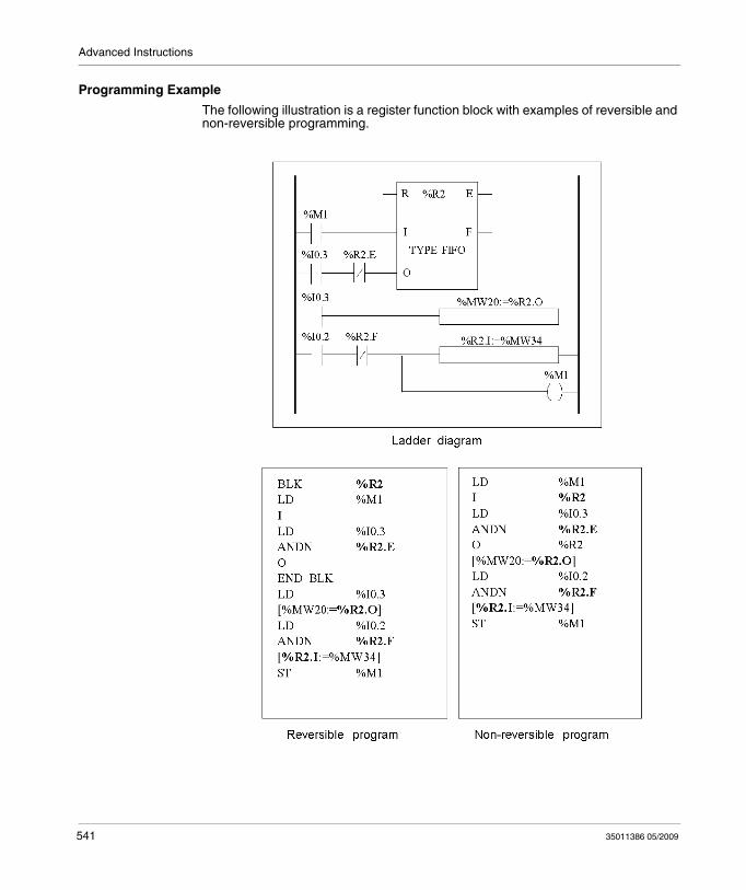
Advanced Instructions
Programming Example
The following illustration is a register function block with examples of reversible and non-reversible programming.
541 35011386 05/2009
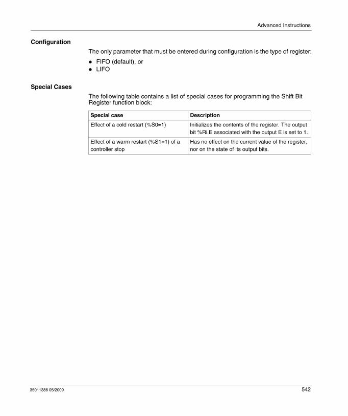
Advanced Instructions
Configuration
The only parameter that must be entered during configuration is the type of register:
FIFO (default), orLIFO
Special Cases
The following table contains a list of special cases for programming the Shift Bit Register function block:
Special case Description
Effect of a cold restart (%S0=1) Initializes the contents of the register. The output bit %Ri.E associated with the output E is set to 1.
Effect of a warm restart (%S1=1) of a controller stop
Has no effect on the current value of the register, nor on the state of its output bits.
35011386 05/2009 542
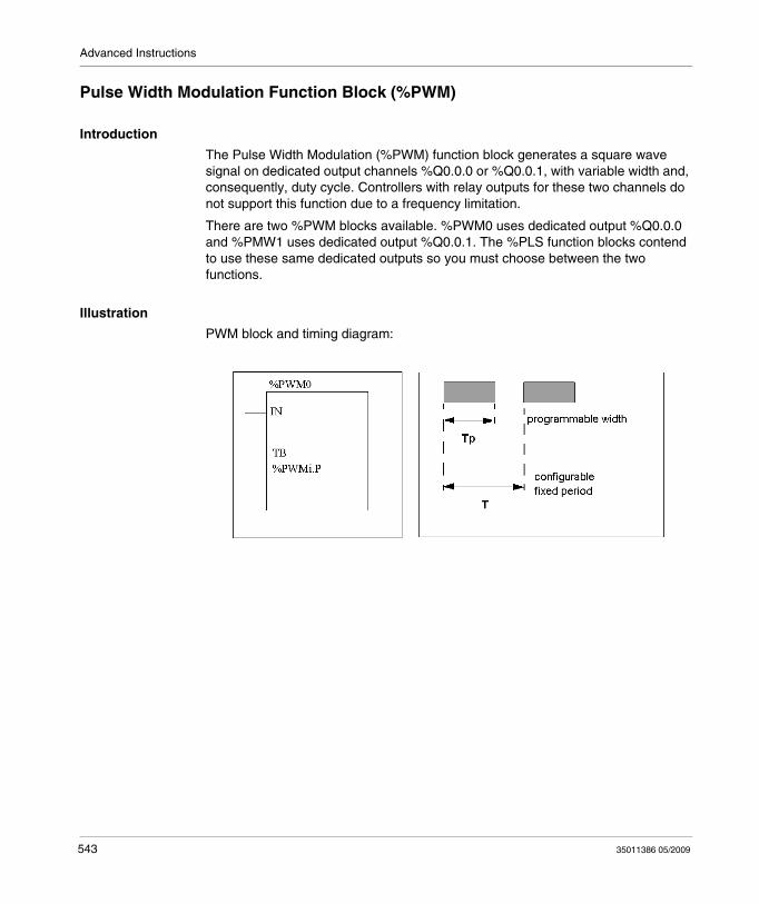
Advanced Instructions
Pulse Width Modulation Function Block (%PWM)
Introduction
The Pulse Width Modulation (%PWM) function block generates a square wave signal on dedicated output channels %Q0.0.0 or %Q0.0.1, with variable width and, consequently, duty cycle. Controllers with relay outputs for these two channels do not support this function due to a frequency limitation.
There are two %PWM blocks available. %PWM0 uses dedicated output %Q0.0.0 and %PMW1 uses dedicated output %Q0.0.1. The %PLS function blocks contend to use these same dedicated outputs so you must choose between the two functions.
Illustration
PWM block and timing diagram:
543 35011386 05/2009
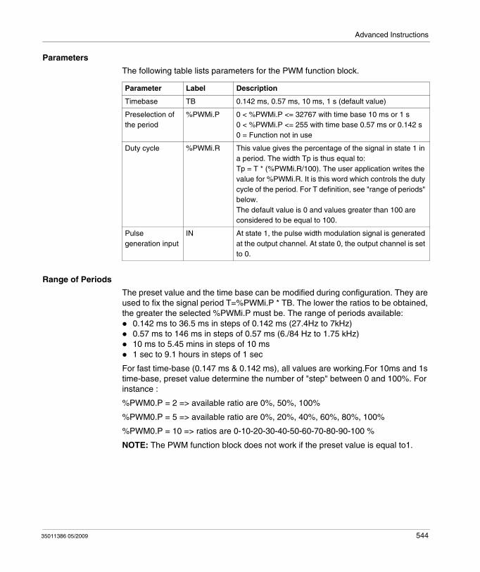
Advanced Instructions
Parameters
The following table lists parameters for the PWM function block.
Range of Periods
The preset value and the time base can be modified during configuration. They are used to fix the signal period T=%PWMi.P * TB. The lower the ratios to be obtained, the greater the selected %PWMi.P must be. The range of periods available:
0.142 ms to 36.5 ms in steps of 0.142 ms (27.4Hz to 7kHz)0.57 ms to 146 ms in steps of 0.57 ms (6./84 Hz to 1.75 kHz)10 ms to 5.45 mins in steps of 10 ms1 sec to 9.1 hours in steps of 1 sec
For fast time-base (0.147 ms & 0.142 ms), all values are working.For 10ms and 1s time-base, preset value determine the number of "step" between 0 and 100%. For instance :
%PWM0.P = 2 => available ratio are 0%, 50%, 100%
%PWM0.P = 5 => available ratio are 0%, 20%, 40%, 60%, 80%, 100%
%PWM0.P = 10 => ratios are 0-10-20-30-40-50-60-70-80-90-100 %
NOTE: The PWM function block does not work if the preset value is equal to1.
Parameter Label Description
Timebase TB 0.142 ms, 0.57 ms, 10 ms, 1 s (default value)
Preselection of the period
%PWMi.P 0 < %PWMi.P <= 32767 with time base 10 ms or 1 s0 < %PWMi.P <= 255 with time base 0.57 ms or 0.142 s0 = Function not in use
Duty cycle %PWMi.R This value gives the percentage of the signal in state 1 in a period. The width Tp is thus equal to:Tp = T * (%PWMi.R/100). The user application writes the value for %PWMi.R. It is this word which controls the duty cycle of the period. For T definition, see "range of periods" below.The default value is 0 and values greater than 100 are considered to be equal to 100.
Pulse generation input
IN At state 1, the pulse width modulation signal is generated at the output channel. At state 0, the output channel is set to 0.
35011386 05/2009 544
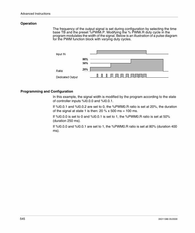
Advanced Instructions
Operation
The frequency of the output signal is set during configuration by selecting the time base TB and the preset %PWMi.P. Modifying the % PWMi.R duty cycle in the program modulates the width of the signal. Below is an illustration of a pulse diagram for the PWM function block with varying duty cycles.
Programming and Configuration
In this example, the signal width is modified by the program according to the state of controller inputs %I0.0.0 and %I0.0.1.
If %I0.0.1 and %I0.0.2 are set to 0, the %PWM0.R ratio is set at 20%, the duration of the signal at state 1 is then: 20 % x 500 ms = 100 ms.
If %I0.0.0 is set to 0 and %I0.0.1 is set to 1, the %PWM0.R ratio is set at 50% (duration 250 ms).
If %I0.0.0 and %I0.0.1 are set to 1, the %PWM0.R ratio is set at 80% (duration 400 ms).
545 35011386 05/2009
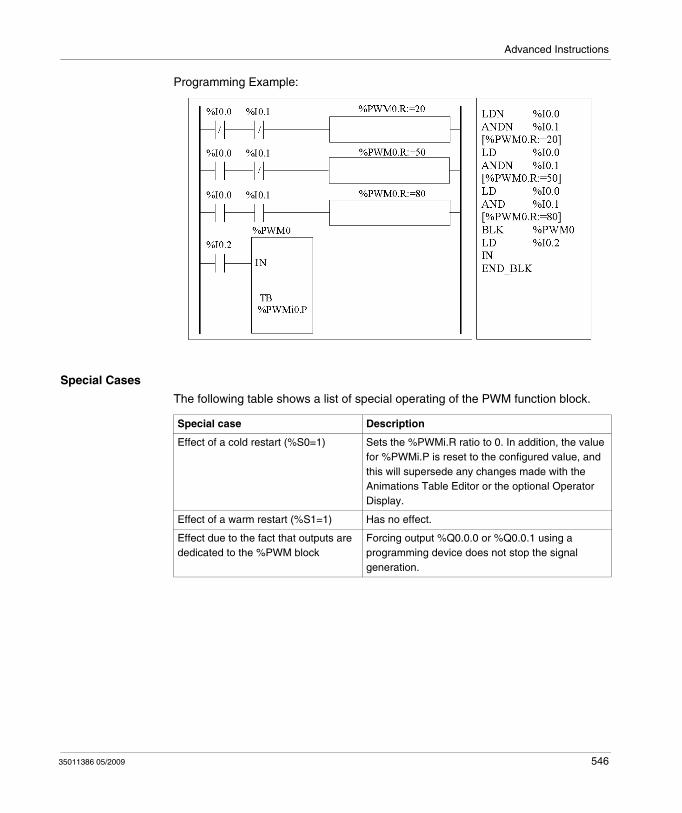
Advanced Instructions
Programming Example:
Special Cases
The following table shows a list of special operating of the PWM function block.
Special case Description
Effect of a cold restart (%S0=1) Sets the %PWMi.R ratio to 0. In addition, the value for %PWMi.P is reset to the configured value, and this will supersede any changes made with the Animations Table Editor or the optional Operator Display.
Effect of a warm restart (%S1=1) Has no effect.
Effect due to the fact that outputs are dedicated to the %PWM block
Forcing output %Q0.0.0 or %Q0.0.1 using a programming device does not stop the signal generation.
35011386 05/2009 546
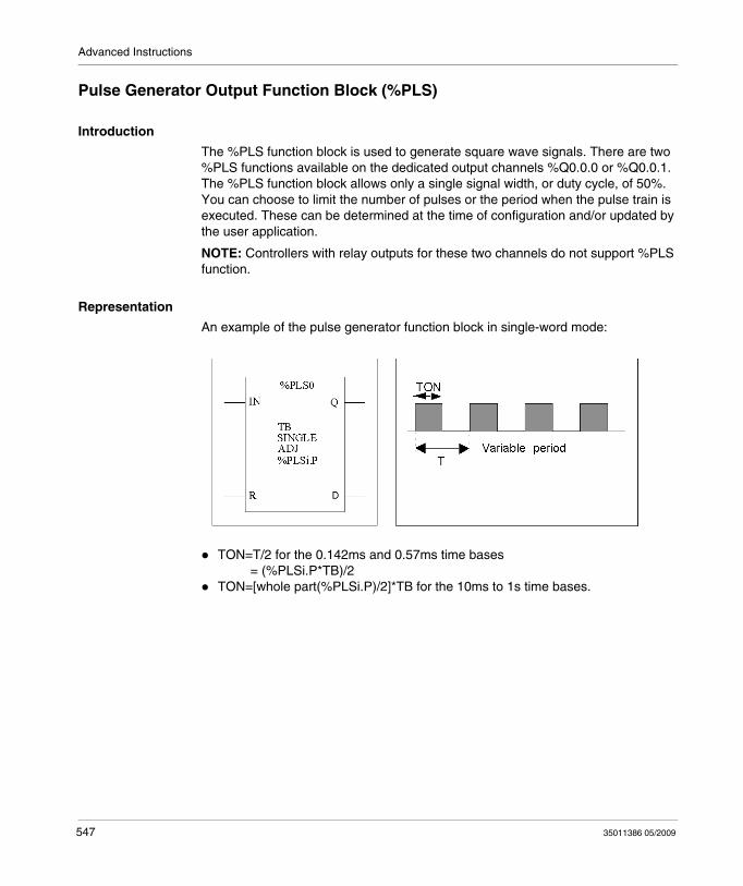
Advanced Instructions
Pulse Generator Output Function Block (%PLS)
Introduction
The %PLS function block is used to generate square wave signals. There are two %PLS functions available on the dedicated output channels %Q0.0.0 or %Q0.0.1. The %PLS function block allows only a single signal width, or duty cycle, of 50%. You can choose to limit the number of pulses or the period when the pulse train is executed. These can be determined at the time of configuration and/or updated by the user application.
NOTE: Controllers with relay outputs for these two channels do not support %PLS function.
Representation
An example of the pulse generator function block in single-word mode:
TON=T/2 for the 0.142ms and 0.57ms time bases = (%PLSi.P*TB)/2TON=[whole part(%PLSi.P)/2]*TB for the 10ms to 1s time bases.
547 35011386 05/2009
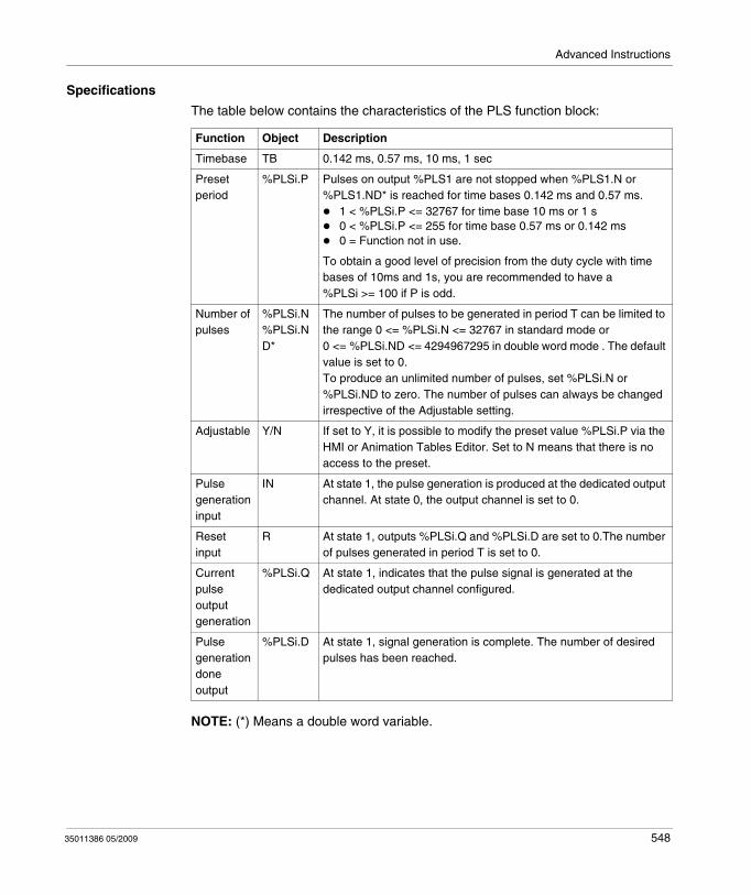
Advanced Instructions
Specifications
The table below contains the characteristics of the PLS function block:
NOTE: (*) Means a double word variable.
Function Object Description
Timebase TB 0.142 ms, 0.57 ms, 10 ms, 1 sec
Preset period
%PLSi.P Pulses on output %PLS1 are not stopped when %PLS1.N or %PLS1.ND* is reached for time bases 0.142 ms and 0.57 ms.
1 < %PLSi.P <= 32767 for time base 10 ms or 1 s0 < %PLSi.P <= 255 for time base 0.57 ms or 0.142 ms0 = Function not in use.
To obtain a good level of precision from the duty cycle with time bases of 10ms and 1s, you are recommended to have a %PLSi >= 100 if P is odd.
Number of pulses
%PLSi.N%PLSi.ND*
The number of pulses to be generated in period T can be limited to the range 0 <= %PLSi.N <= 32767 in standard mode or 0 <= %PLSi.ND <= 4294967295 in double word mode . The default value is set to 0.To produce an unlimited number of pulses, set %PLSi.N or %PLSi.ND to zero. The number of pulses can always be changed irrespective of the Adjustable setting.
Adjustable Y/N If set to Y, it is possible to modify the preset value %PLSi.P via the HMI or Animation Tables Editor. Set to N means that there is no access to the preset.
Pulse generation input
IN At state 1, the pulse generation is produced at the dedicated output channel. At state 0, the output channel is set to 0.
Reset input
R At state 1, outputs %PLSi.Q and %PLSi.D are set to 0.The number of pulses generated in period T is set to 0.
Current pulse output generation
%PLSi.Q At state 1, indicates that the pulse signal is generated at the dedicated output channel configured.
Pulse generation done output
%PLSi.D At state 1, signal generation is complete. The number of desired pulses has been reached.
35011386 05/2009 548
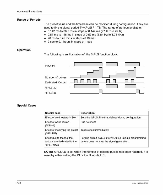
Advanced Instructions
Range of Periods
The preset value and the time base can be modified during configuration. They are used to fix the signal period T=%PLSi.P * TB. The range of periods available:
0.142 ms to 36.5 ms in steps of 0.142 ms (27.4Hz to 7kHz)0.57 ms to 146 ms in steps of 0.57 ms (6.84 Hz to 1.75 kHz)20 ms to 5.45 mins in steps of 10 ms2 sec to 9.1 hours in steps of 1 sec
Operation
The following is an illustration of the %PLS function block.
Special Cases
NOTE: %PLSx.D is set when the number of desired pulses has been reached. It is reset by either setting the IN or the R inputs to 1.
Special case Description
Effect of cold restart (%S0=1) Sets the %PLSi.P to that defined during configuration
Effect of warm restart (%S1=1)
Has no effect
Effect of modifying the preset (%PLSi.P)
Takes effect immediately
Effect due to the fact that outputs are dedicated to the %PLS block
Forcing output %Q0.0.0 or %Q0.0.1 using a programming device does not stop the signal generation.
549 35011386 05/2009
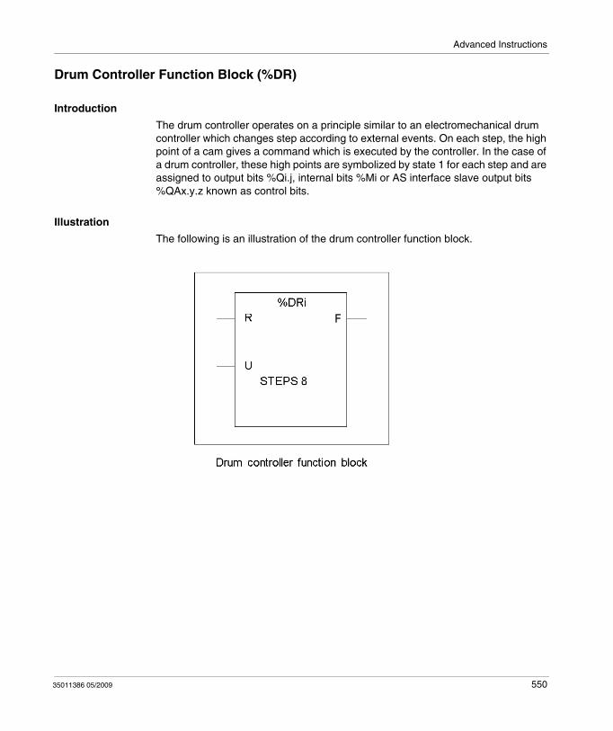
Advanced Instructions
Drum Controller Function Block (%DR)
Introduction
The drum controller operates on a principle similar to an electromechanical drum controller which changes step according to external events. On each step, the high point of a cam gives a command which is executed by the controller. In the case of a drum controller, these high points are symbolized by state 1 for each step and are assigned to output bits %Qi.j, internal bits %Mi or AS interface slave output bits %QAx.y.z known as control bits.
Illustration
The following is an illustration of the drum controller function block.
35011386 05/2009 550
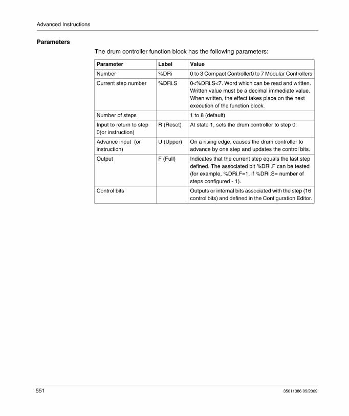
Advanced Instructions
Parameters
The drum controller function block has the following parameters:
Parameter Label Value
Number %DRi 0 to 3 Compact Controller0 to 7 Modular Controllers
Current step number %DRi.S 0<%DRi.S<7. Word which can be read and written. Written value must be a decimal immediate value. When written, the effect takes place on the next execution of the function block.
Number of steps 1 to 8 (default)
Input to return to step 0(or instruction)
R (Reset) At state 1, sets the drum controller to step 0.
Advance input (or instruction)
U (Upper) On a rising edge, causes the drum controller to advance by one step and updates the control bits.
Output F (Full) Indicates that the current step equals the last step defined. The associated bit %DRi.F can be tested (for example, %DRi.F=1, if %DRi.S= number of steps configured - 1).
Control bits Outputs or internal bits associated with the step (16 control bits) and defined in the Configuration Editor.
551 35011386 05/2009
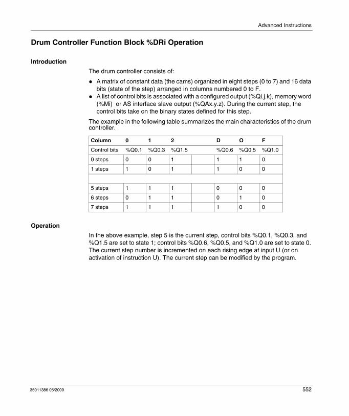
Advanced Instructions
Drum Controller Function Block %DRi Operation
Introduction
The drum controller consists of:
A matrix of constant data (the cams) organized in eight steps (0 to 7) and 16 data bits (state of the step) arranged in columns numbered 0 to F.A list of control bits is associated with a configured output (%Qi.j.k), memory word (%Mi) or AS interface slave output (%QAx.y.z). During the current step, the control bits take on the binary states defined for this step.
The example in the following table summarizes the main characteristics of the drum controller.
Operation
In the above example, step 5 is the current step, control bits %Q0.1, %Q0.3, and %Q1.5 are set to state 1; control bits %Q0.6, %Q0.5, and %Q1.0 are set to state 0. The current step number is incremented on each rising edge at input U (or on activation of instruction U). The current step can be modified by the program.
Column 0 1 2 D O F
Control bits %Q0.1 %Q0.3 %Q1.5 %Q0.6 %Q0.5 %Q1.0
0 steps 0 0 1 1 1 0
1 steps 1 0 1 1 0 0
5 steps 1 1 1 0 0 0
6 steps 0 1 1 0 1 0
7 steps 1 1 1 1 0 0
35011386 05/2009 552
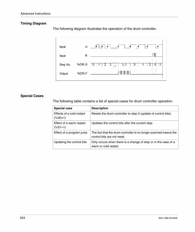
Advanced Instructions
Timing Diagram
The following diagram illustrates the operation of the drum controller.
Special Cases
The following table contains a list of special cases for drum controller operation.
Special case Description
Effects of a cold restart (%S0=1)
Resets the drum controller to step 0 (update of control bits).
Effect of a warm restart (%S1=1)
Updates the control bits after the current step.
Effect of a program jump The fact that the drum controller is no longer scanned means the control bits are not reset.
Updating the control bits Only occurs when there is a change of step or in the case of a warm or cold restart.
553 35011386 05/2009
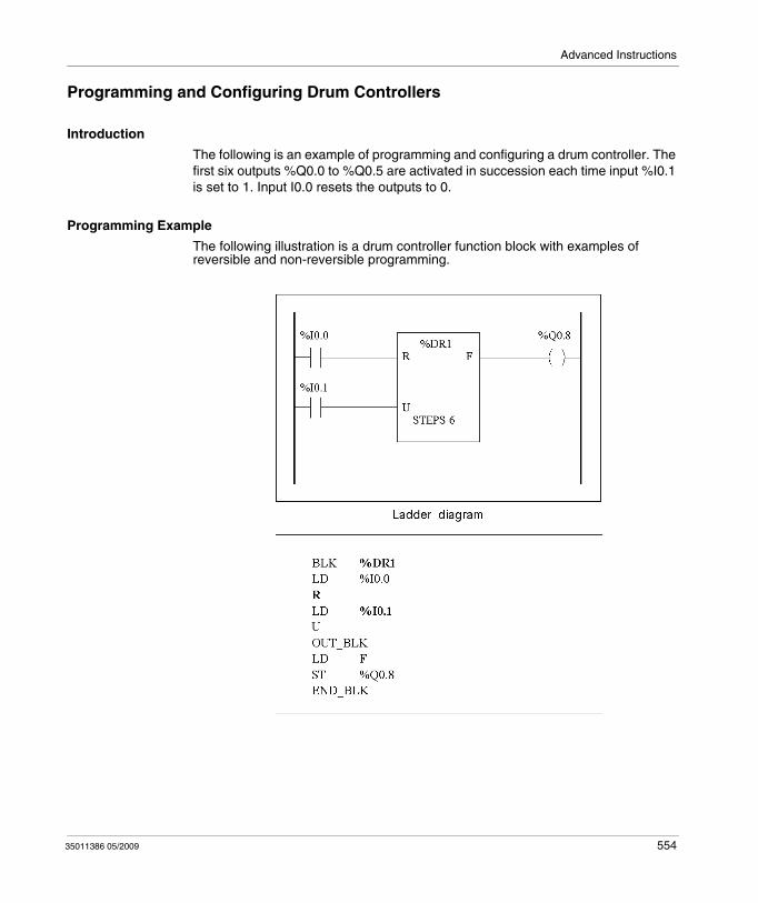
Advanced Instructions
Programming and Configuring Drum Controllers
Introduction
The following is an example of programming and configuring a drum controller. The first six outputs %Q0.0 to %Q0.5 are activated in succession each time input %I0.1 is set to 1. Input I0.0 resets the outputs to 0.
Programming Example
The following illustration is a drum controller function block with examples of reversible and non-reversible programming.
35011386 05/2009 554
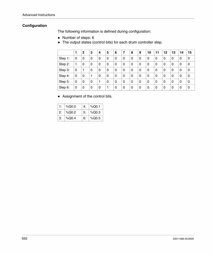
Advanced Instructions
Configuration
The following information is defined during configuration:
Number of steps: 6The output states (control bits) for each drum controller step.
Assignment of the control bits.
1 2 3 4 5 6 7 8 9 10 11 12 13 14 15
Step 1: 0 0 0 0 0 0 0 0 0 0 0 0 0 0 0
Step 2: 1 0 0 0 0 0 0 0 0 0 0 0 0 0 0
Step 3: 0 1 0 0 0 0 0 0 0 0 0 0 0 0 0
Step 4: 0 0 1 0 0 0 0 0 0 0 0 0 0 0 0
Step 5: 0 0 0 1 0 0 0 0 0 0 0 0 0 0 0
Step 6: 0 0 0 0 1 0 0 0 0 0 0 0 0 0 0
1: %Q0.0 4: %Q0.1
2: %Q0.2 5: %Q0.3
3: %Q0.4 6: %Q0.5
555 35011386 05/2009
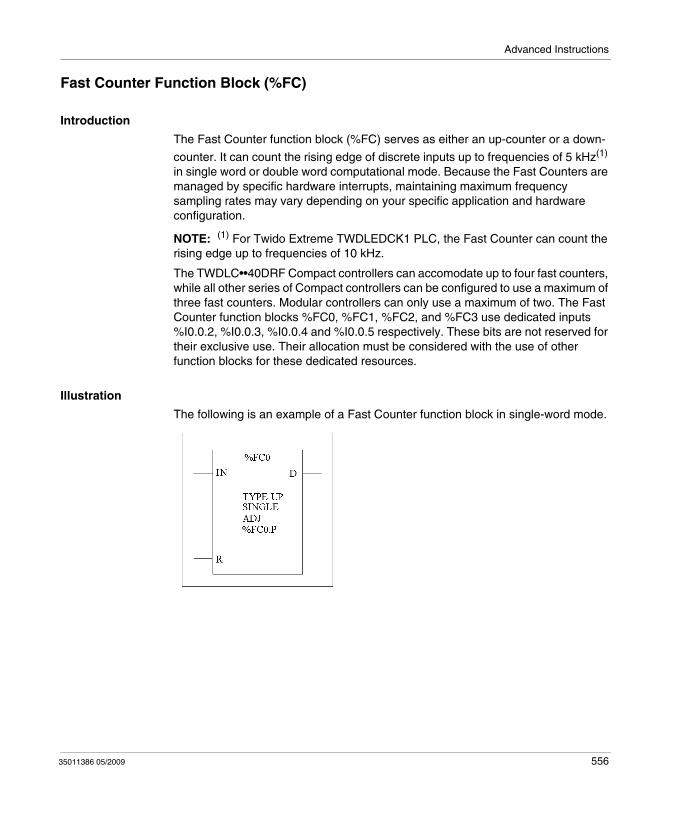
Advanced Instructions
Fast Counter Function Block (%FC)
Introduction
The Fast Counter function block (%FC) serves as either an up-counter or a down-
counter. It can count the rising edge of discrete inputs up to frequencies of 5 kHz(1) in single word or double word computational mode. Because the Fast Counters are managed by specific hardware interrupts, maintaining maximum frequency sampling rates may vary depending on your specific application and hardware configuration.
NOTE: (1) For Twido Extreme TWDLEDCK1 PLC, the Fast Counter can count the rising edge up to frequencies of 10 kHz.
The TWDLC••40DRF Compact controllers can accomodate up to four fast counters, while all other series of Compact controllers can be configured to use a maximum of three fast counters. Modular controllers can only use a maximum of two. The Fast Counter function blocks %FC0, %FC1, %FC2, and %FC3 use dedicated inputs %I0.0.2, %I0.0.3, %I0.0.4 and %I0.0.5 respectively. These bits are not reserved for their exclusive use. Their allocation must be considered with the use of other function blocks for these dedicated resources.
Illustration
The following is an example of a Fast Counter function block in single-word mode.
35011386 05/2009 556
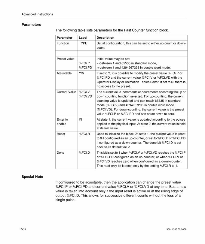
Advanced Instructions
Parameters
The following table lists parameters for the Fast Counter function block.
Special Note
If configured to be adjustable, then the application can change the preset value %FCi.P or %FCi.PD and current value %FCi.V or %FCi.VD at any time. But, a new value is taken into account only if the input reset is active or at the rising edge of output %FCi.D. This allows for successive different counts without the loss of a single pulse.
Parameter Label Description
Function TYPE Set at configuration, this can be set to either up-count or down-count.
Preset value %FCi.P%FCi.PD
Initial value may be set:->between 1 and 65535 in standard mode,->between 1 and 4294967295 in double word mode,
Adjustable Y/N If set to Y, it is possible to modify the preset value %FCi.P or %FCi.PD and the current value %FCi.V or %FCi.VD with the Operator Display or Animation Tables Editor. If set to N, there is no access to the preset.
Current Value %FCi.V%FCi.VD
The current value increments or decrements according the up or down counting function selected. For up-counting, the current counting value is updated and can reach 65535 in standard mode (%FCi.V) and 4294967295 in double word mode (%FCi.VD). For down-counting, the current value is the preset value %FCi.P or %FCi.PD and can count down to zero.
Enter to enable
IN At state 1, the current value is updated according to the pulses applied to the physical input. At state 0, the current value is held at its last value.
Reset %FCi.R Used to initialize the block. At state 1, the current value is reset to 0 if configured as an up-counter, or set to %FCi.P or %FCi.PD if configured as a down-counter. The done bit %FCi.D is set back to its default value.
Done %FCi.D This bit is set to 1 when %FCi.V or %FCi.VD reaches the %FCi.P or %FCi.PD configured as an up-counter, or when %FCi.V or %FCi.VD reaches zero when configured as a down-counter.This read-only bit is reset only by the setting %FCi.R to 1.
557 35011386 05/2009
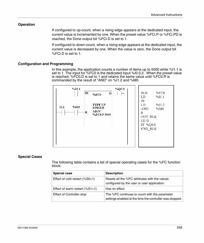
Advanced Instructions
Operation
If configured to up-count, when a rising edge appears at the dedicated input, the current value is incremented by one. When the preset value %FCi.P or %FCi.PD is reached, the Done output bit %FCi.D is set to 1.
If configured to down-count, when a rising edge appears at the dedicated input, the current value is decreased by one. When the value is zero, the Done output bit %FCi.D is set to 1.
Configuration and Programming
In this example, the application counts a number of items up to 5000 while %I1.1 is set to 1. The input for %FC0 is the dedicated input %I0.0.2. When the preset value is reached, %FC0.D is set to 1 and retains the same value until %FC0.R is commanded by the result of "AND" on %I1.2 and %M0.
Special Cases
The following table contains a list of special operating cases for the %FC function block:
Special case Description
Effect of cold restart (%S0=1) Resets all the %FC attributes with the values configured by the user or user application.
Effect of warm restart (%S1=1) Has no effect.
Effect of Controller stop The %FC continues to count with the parameter settings enabled at the time the controller was stopped.
35011386 05/2009 558
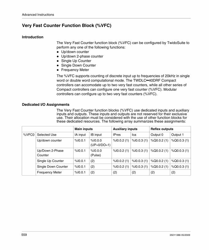
Advanced Instructions
Very Fast Counter Function Block (%VFC)
Introduction
The Very Fast Counter function block (%VFC) can be configured by TwidoSuite to perform any one of the following functions:
Up/down counterUp/down 2-phase counterSingle Up CounterSingle Down CounterFrequency Meter
The %VFC supports counting of discrete input up to frequencies of 20kHz in single word or double word computational mode. The TWDLC••40DRF Compact controllers can accomodate up to two very fast counters, while all other series of Compact controllers can configure one very fast counter (%VFC). Modular controllers can configure up to two very fast counters (%VFC).
Dedicated I/O Assignments
The Very Fast Counter function blocks (%VFC) use dedicated inputs and auxiliary inputs and outputs. These inputs and outputs are not reserved for their exclusive use. Their allocation must be considered with the use of other function blocks for these dedicated resources. The following array summarizes these assignments:
Main inputs Auxiliary inputs Reflex outputs
%VFC0 Selected Use IA input IB input IPres Ica Output 0 Output 1
Up/down counter %I0.0.1 %I0.0.0(UP=0/DO=1)
%I0.0.2 (1) %I0.0.3 (1) %Q0.0.2 (1) %Q0.0.3 (1)
Up/Down 2-Phase Counter
%I0.0.1 %I0.0.0 (Pulse)
%I0.0.2 (1) %I0.0.3 (1) %Q0.0.2 (1) %Q0.0.3 (1)
Single Up Counter %I0.0.1 (2) %I0.0.2 (1) %I0.0.3 (1) %Q0.0.2 (1) %Q0.0.3 (1)
Single Down Counter %I0.0.1 (2) %I0.0.2 (1) %I0.0.3 (1) %Q0.0.2 (1) %Q0.0.3 (1)
Frequency Meter %I0.0.1 (2) (2) (2) (2) (2)
559 35011386 05/2009
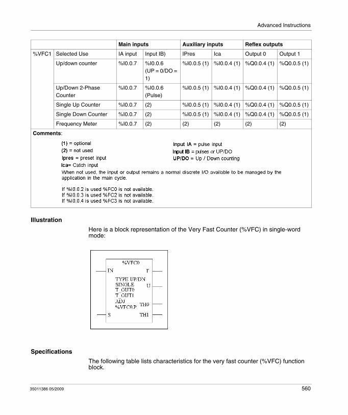
Advanced Instructions
Illustration
Here is a block representation of the Very Fast Counter (%VFC) in single-word mode:
Specifications
The following table lists characteristics for the very fast counter (%VFC) function block.
%VFC1 Selected Use IA input Input IB) IPres Ica Output 0 Output 1
Up/down counter %I0.0.7 %I0.0.6 (UP = 0/DO = 1)
%I0.0.5 (1) %I0.0.4 (1) %Q0.0.4 (1) %Q0.0.5 (1)
Up/Down 2-Phase Counter
%I0.0.7 %I0.0.6 (Pulse)
%I0.0.5 (1) %I0.0.4 (1) %Q0.0.4 (1) %Q0.0.5 (1)
Single Up Counter %I0.0.7 (2) %I0.0.5 (1) %I0.0.4 (1) %Q0.0.4 (1) %Q0.0.5 (1)
Single Down Counter %I0.0.7 (2) %I0.0.5 (1) %I0.0.4 (1) %Q0.0.4 (1) %Q0.0.5 (1)
Frequency Meter %I0.0.7 (2) (2) (2) (2) (2)
Comments:
Main inputs Auxiliary inputs Reflex outputs
35011386 05/2009 560
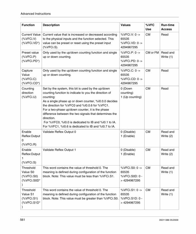
Advanced Instructions
Function Description Values %VFC Use
Run-time Access
Current Value(%VFCi.V)(%VFCi.VD*)
Current value that is increased or decreased according to the physical inputs and the function selected. This value can be preset or reset using the preset input (%VFCi.S).
%VFCi.V: 0 -> 65535%VFCi.VD: 0 -> 4294967295
CM Read
Preset value(%VFCi.P)(%VFCi.PD*)
Only used by the up/down counting function and single up or down counting.
%VFCi.P: 0 -> 65535%VFCi.PD: 0 -> 4294967295
CM or FM Read and Write (1)
Capture Value(%VFCi.C)(%VFCi.CD*)
Only used by the up/down counting function and single up or down counting.
%VFCi.C: 0 -> 65535%VFCi.CD: 0 -> 4294967295
CM Read
Counting direction(%VFCi.U)
Set by the system, this bit is used by the up/down counting function to indicate to you the direction of counting:As a single phase up or down counter, %I0.0.0 decides the direction for %VFC0 and %I0.0.6 for %VFC1.For a two-phase up/down counter, it is the phase difference between the two signals that determines the direction. For %VFC0, %I0.0 is dedicated to IB and %I0.1 to IA. For %VFC1, %I0.6 is dedicated to IB and %I0.7 to IA.
0 (Down counting)1 (Up counting)
CM Read
Enable Reflex Output 0(%VFCi.R)
Validate Reflex Output 0 0 (Disable)1 (Enable)
CM Read and Write (2)
Enable Reflex Output 1(%VFCi.S)
Validate Reflex Output 1 0 (Disable)1 (Enable)
CM Read and Write (2)
Threshold Value S0(%VFCi.S0)(%VFCi.S0D*)
This word contains the value of threshold 0. The meaning is defined during configuration of the function block. Note: This value must be less than %VFCi.S1.
%VFCi.S0: 0 -> 65535%VFCi.S0D: 0 -> 4294967295
CM Read and Write (1)
Threshold Value S1(%VFCi.S1)(%VFCi.S1D*)
This word contains the value of threshold 0. The meaning is defined during configuration of the function block. Note: This value must be greater than %VFCi.S0.
%VFCi.S1: 0 -> 65535%VFCi.S1D: 0 -> 4294967295
CM Read and Write (1)
561 35011386 05/2009
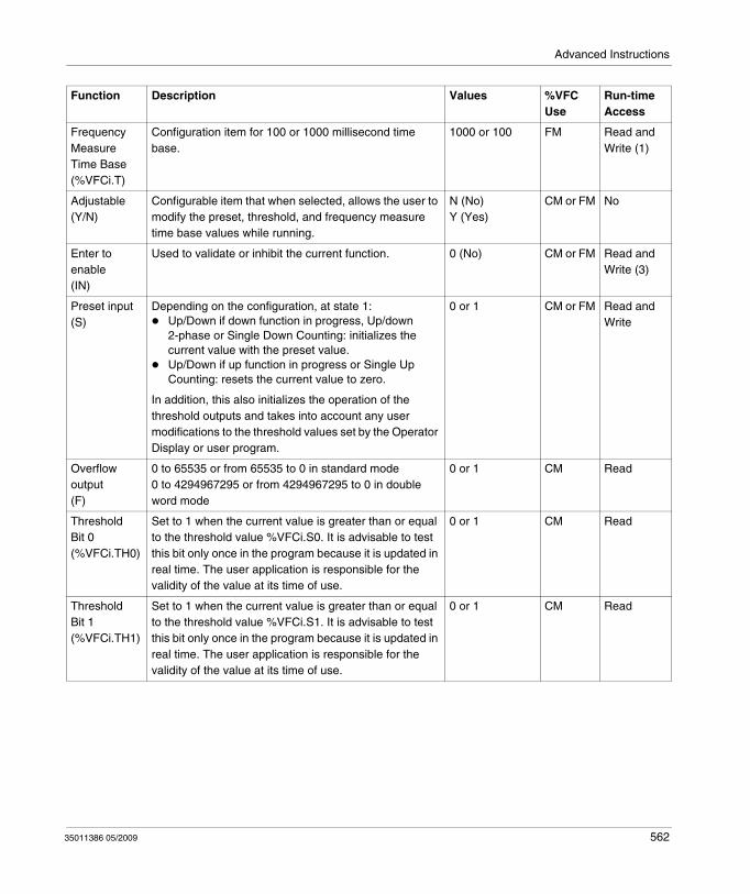
Advanced Instructions
Frequency Measure Time Base(%VFCi.T)
Configuration item for 100 or 1000 millisecond time base.
1000 or 100 FM Read and Write (1)
Adjustable(Y/N)
Configurable item that when selected, allows the user to modify the preset, threshold, and frequency measure time base values while running.
N (No)Y (Yes)
CM or FM No
Enter to enable(IN)
Used to validate or inhibit the current function. 0 (No) CM or FM Read and Write (3)
Preset input(S)
Depending on the configuration, at state 1:Up/Down if down function in progress, Up/down 2-phase or Single Down Counting: initializes the current value with the preset value.Up/Down if up function in progress or Single Up Counting: resets the current value to zero.
In addition, this also initializes the operation of the threshold outputs and takes into account any user modifications to the threshold values set by the Operator Display or user program.
0 or 1 CM or FM Read and Write
Overflow output(F)
0 to 65535 or from 65535 to 0 in standard mode0 to 4294967295 or from 4294967295 to 0 in double word mode
0 or 1 CM Read
ThresholdBit 0(%VFCi.TH0)
Set to 1 when the current value is greater than or equal to the threshold value %VFCi.S0. It is advisable to test this bit only once in the program because it is updated in real time. The user application is responsible for the validity of the value at its time of use.
0 or 1 CM Read
ThresholdBit 1(%VFCi.TH1)
Set to 1 when the current value is greater than or equal to the threshold value %VFCi.S1. It is advisable to test this bit only once in the program because it is updated in real time. The user application is responsible for the validity of the value at its time of use.
0 or 1 CM Read
Function Description Values %VFC Use
Run-time Access
35011386 05/2009 562
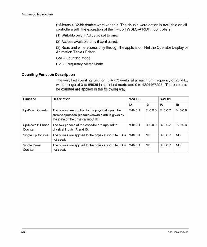
Advanced Instructions
(*)Means a 32-bit double word variable. The double word option is available on all controllers with the exception of the Twido TWDLC•A10DRF controllers.
(1) Writable only if Adjust is set to one.
(2) Access available only if configured.
(3) Read and write access only through the application. Not the Operator Display or Animation Tables Editor.
CM = Counting Mode
FM = Frequency Meter Mode
Counting Function Description
The very fast counting function (%VFC) works at a maximum frequency of 20 kHz, with a range of 0 to 65535 in standard mode and 0 to 4294967295. The pulses to be counted are applied in the following way:
Function Description %VFC0 %VFC1
IA IB IA IB
Up/Down Counter The pulses are applied to the physical input, the current operation (upcount/downcount) is given by the state of the physical input IB.
%I0.0.1 %I0.0.0 %I0.0.7 %I0.0.6
Up/Down 2-Phase Counter
The two phases of the encoder are applied to physical inputs IA and IB.
%I0.0.1 %I0.0.0 %I0.0.7 %I0.0.6
Single Up Counter The pulses are applied to the physical input IA. IB is not used.
%I0.0.1 ND %I0.0.7 ND
Single Down Counter
The pulses are applied to the physical input IA. IB is not used.
%I0.0.1 ND %I0.0.7 ND
563 35011386 05/2009
Advanced Instructions
Notes on Function Blocks
Upcount or downcount operations are made on the rising edge of pulses, and only if the counting block is enabled.
There are two optional inputs used in counting mode: ICa and IPres. ICa is used to capture the current value (%VFCi.V or %VFCi.VD) and stored it in %VFCi.C or %VFCi.CD. The Ica inputs are specified as %I0.0.3 for %VFC0 and %I0.0.4 for %VFC1 if available.
When IPres input is active, the current value is affected in the following ways:
For up counting, %VFCi.V or %VFCi.VD is reset to 0For downcounting, %VFCi.V or %VFCi.VD is written with the content of %VFCi.P or %VFCi.PD, respectively.For frequency counting, %VFCi.V or %VFCi.PD is set to 0
Important: %VFCi.F is also set to 0. The IPres inputs are specified as %I0.0.2 for %VFC0 and %I0.0.5 for %VFC1 if available.
Notes on Function Block Outputs
For all functions, the current value is compared to two thresholds (%VFCi.S0 or %VFCi.S0D and % VFCi.S1 or %VFCi.S1D). According to the result of this comparison two bit objects (%VFCi.TH0 and %VFCi.TH1) are set to 1 if the current value is greater or equal to the corresponding threshold, or reset to 0 in the opposite case. Reflex outputs (if configured) are set to 1 in accordance with these comparisons. Note: None, 1 or 2 outputs can be configured.
%VFC.U is an output of the FB, it gives the direction of the associated counter variation (1 for UP, 0 for DOWN).
35011386 05/2009 564
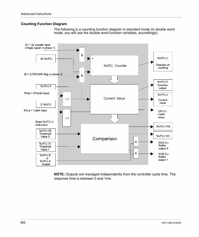
Advanced Instructions
Counting Function Diagram
The following is a counting function diagram in standard mode (in double word mode, you will use the double word function variables, accordingly):
NOTE: Outputs are managed independently from the controller cycle time. The response time is between 0 and 1ms.
565 35011386 05/2009

Advanced Instructions
Single Up Counter Operation
The following is an example of using %VFC in a single up counter mode. The following configuration elements have been set for this example:
%VFC0.P preset value is 17, while the %VFC0.S0 lower threshold value is 14, and the %VFC0.S1 upper threshold is 20.
Reflex Output
value < %VFC.S0 %VFC0.S0 <= value < %VFC0.S1 value >= %VFC0.S1
%Q0.0.2 X
%Q0.0.3 X X
35011386 05/2009 566
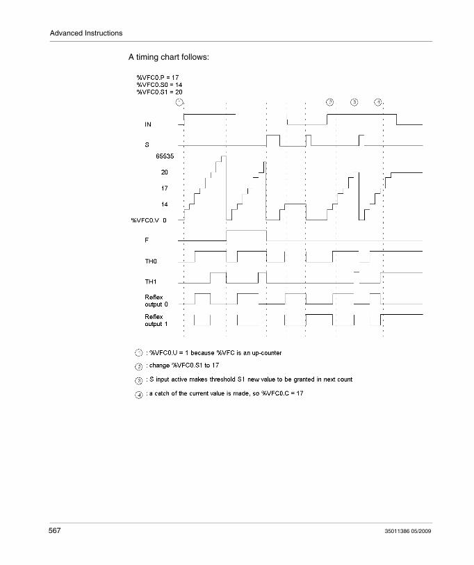
Advanced Instructions
A timing chart follows:
567 35011386 05/2009
Advanced Instructions
Single Down Counter Operation
The following is an example of using %VFC in a single down counter mode. The following configuration elements have been set for this example:
%VFC0.P preset value is 17, while the %VFC0.S0 lower threshold value is 14, and the %VFC0.S1 upper threshold is 20.
Reflex Output
value < %VFC.S0 %VFC0.S0 <= value < %VFC0.S1 value >= %VFC0.S1
%Q0.0.2 X X
%Q0.0.3 X
35011386 05/2009 568
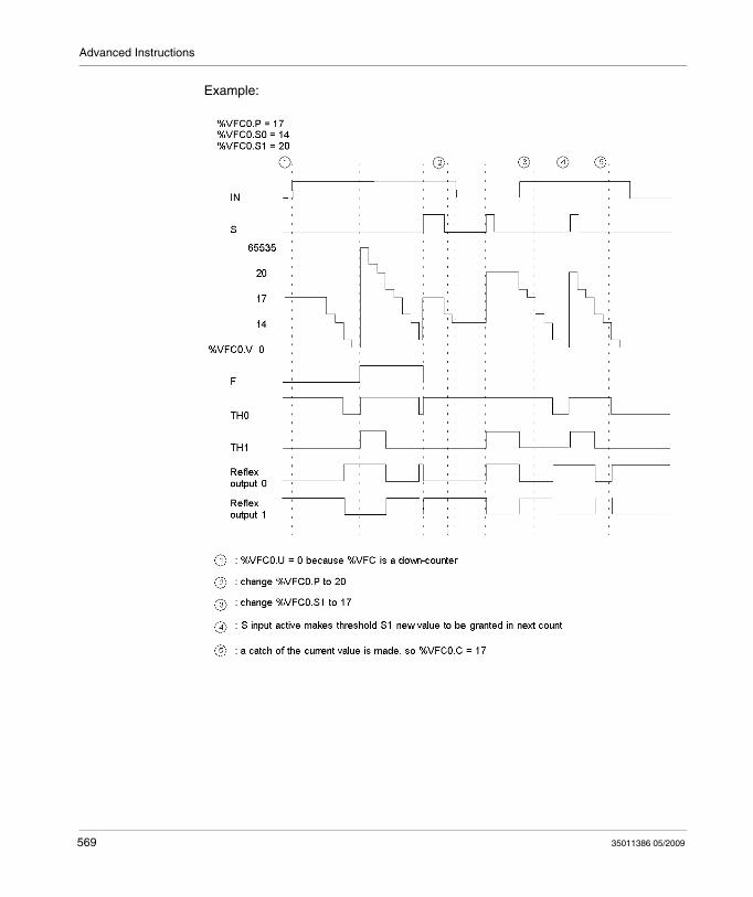
Advanced Instructions
Example:
569 35011386 05/2009

Advanced Instructions
Up-Down Counter Operation
The following is an example of using %VFC in an up-down counter mode. The following configuration elements have been set for this example:
%VFC0.P preset value is 17, while the %VFC0.S0 lower threshold value is 14, and the %VFC0.S1 upper threshold is 20.
Reflex Output
value < %VFC.S0 %VFC0.S0 <= value < %VFC0.S1 value >= %VFC0.S1
%Q0.0.2 X
%Q0.0.3 X X
35011386 05/2009 570
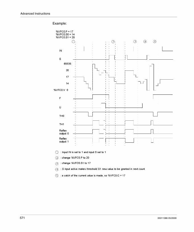
Advanced Instructions
Example:
571 35011386 05/2009
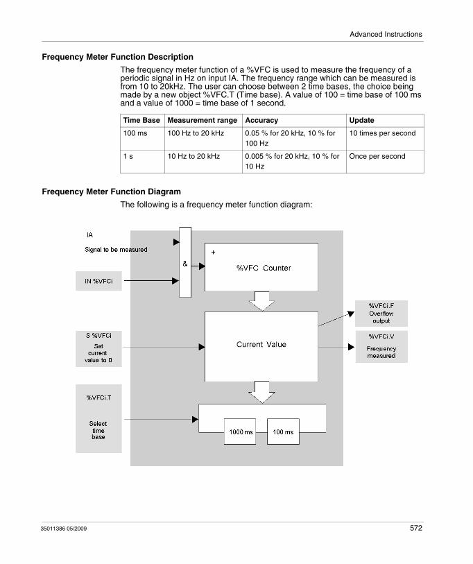
Advanced Instructions
Frequency Meter Function Description
The frequency meter function of a %VFC is used to measure the frequency of a periodic signal in Hz on input IA. The frequency range which can be measured is from 10 to 20kHz. The user can choose between 2 time bases, the choice being made by a new object %VFC.T (Time base). A value of 100 = time base of 100 ms and a value of 1000 = time base of 1 second.
Frequency Meter Function Diagram
The following is a frequency meter function diagram:
Time Base Measurement range Accuracy Update
100 ms 100 Hz to 20 kHz 0.05 % for 20 kHz, 10 % for 100 Hz
10 times per second
1 s 10 Hz to 20 kHz 0.005 % for 20 kHz, 10 % for 10 Hz
Once per second
35011386 05/2009 572
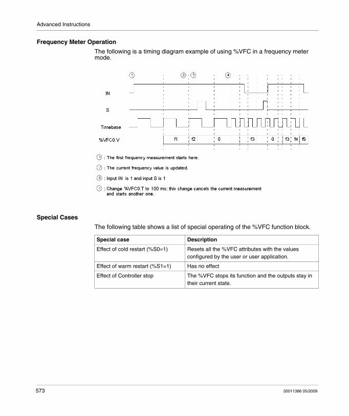
Advanced Instructions
Frequency Meter Operation
The following is a timing diagram example of using %VFC in a frequency meter mode.
Special Cases
The following table shows a list of special operating of the %VFC function block.
Special case Description
Effect of cold restart (%S0=1) Resets all the %VFC attributes with the values configured by the user or user application.
Effect of warm restart (%S1=1) Has no effect
Effect of Controller stop The %VFC stops its function and the outputs stay in their current state.
573 35011386 05/2009
Advanced Instructions
Transmitting/Receiving Messages - the Exchange Instruction (EXCH)
Introduction
A Twido controller can be configured to communicate with Modbus slave devices or can send and/or receive messages in character mode (ASCII).
TwidoSuite provides the following functions for these communications:EXCH instruction to transmit/receive messagesExchange control function block (%MSG) to control the data exchanges
The Twido controller uses the protocol configured for the specified port when processing an EXCH instruction. Each communication port can be assigned a different protocol. The communication ports are accessed by appending the port number to the EXCH or %MSG function (EXCH1, EXCH2, %MSG1, %MSG2).
In addition, TWDLC•E40DRF series controllers implement Modbus TCP messaging over the Ethernet network by using the EXCH3 intruction and %MSG3 function.
EXCH Instruction
The EXCH instruction allows a Twido controller to send and/or receive information to/from ASCII devices. The user defines a table of words (%MWi:L) containing the data to be sent and/or received (up to 250 data bytes in transmission and/or reception). The format for the word table is described in the paragraphs about each protocol. A message exchange is performed using the EXCH instruction.
Syntax
The following is the format for the EXCH instruction:
[EXCHx %MWi:L]
Where: x = serial port number (1 or 2); x = Ethernet port (3); L = total number of words of the word table (maximum 121). Values of the internal word table %MWi:L are such as i+L <= 255.
The Twido controller must finish the exchange from the first EXCHx instruction before a second exchange instruction can be started. The %MSG function block must be used when sending several messages.
NOTE: To find out more information about the Modbus TCP messaging instruction EXCH3, please refer to .
35011386 05/2009 574
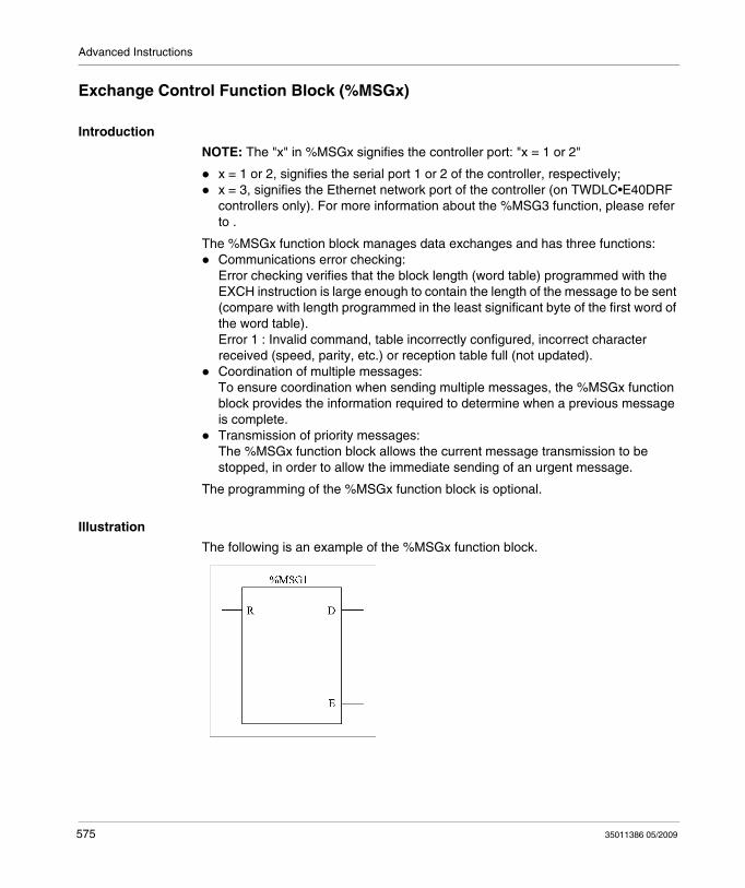
Advanced Instructions
Exchange Control Function Block (%MSGx)
Introduction
NOTE: The "x" in %MSGx signifies the controller port: "x = 1 or 2"
x = 1 or 2, signifies the serial port 1 or 2 of the controller, respectively;x = 3, signifies the Ethernet network port of the controller (on TWDLC•E40DRF controllers only). For more information about the %MSG3 function, please refer to .
The %MSGx function block manages data exchanges and has three functions:Communications error checking:Error checking verifies that the block length (word table) programmed with the EXCH instruction is large enough to contain the length of the message to be sent (compare with length programmed in the least significant byte of the first word of the word table).Error 1 : Invalid command, table incorrectly configured, incorrect character received (speed, parity, etc.) or reception table full (not updated).Coordination of multiple messages:To ensure coordination when sending multiple messages, the %MSGx function block provides the information required to determine when a previous message is complete.Transmission of priority messages:The %MSGx function block allows the current message transmission to be stopped, in order to allow the immediate sending of an urgent message.
The programming of the %MSGx function block is optional.
Illustration
The following is an example of the %MSGx function block.
575 35011386 05/2009
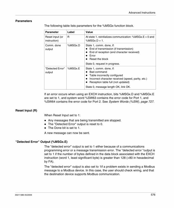
Advanced Instructions
Parameters
The following table lists parameters for the %MSGx function block.
If an error occurs when using an EXCH instruction, bits %MSGx.D and %MSGx.E are set to 1, and system word %SW63 contains the error code for Port 1, and %SW64 contains the error code for Port 2. See System Words (%SW), page 727.
Reset Input (R)
When Reset Input set to 1:
Any messages that are being transmitted are stopped.The "Detected Error" output is reset to 0.The Done bit is set to 1.
A new message can now be sent.
"Detected Error" Output (%MSGx.E)
The "detected error" output is set to 1 either because of a communications programming error or a message transmission error. The "detected error "output is set to 1 if the number of bytes defined in the data block associated with the EXCH instruction (word 1, least significant byte) is greater than 128 (+80 in hexadecimal by FA).
The "detected error" output is also set to 1if a problem exists in sending a Modbus message to a Modbus device. In this case, the user should check wiring, and that the destination device supports Modbus communication.
Parameter Label Value
Reset input (or instruction)
R At state 1, reinitializes communication: %MSGx.E = 0 and %MSGx.D = 1.
Comm. done output
%MSGx.D State 1, comm. done, if:End of transmission (if transmission)End of reception (end character received)ErrorReset the block
State 0, request in progress.
"Detected Error" output
%MSGx.E State 1, comm. done, if:Bad commandTable incorrectly configuredIncorrect character received (speed, parity, etc.)Reception table full (not updated)
State 0, message length OK, link OK.
35011386 05/2009 576
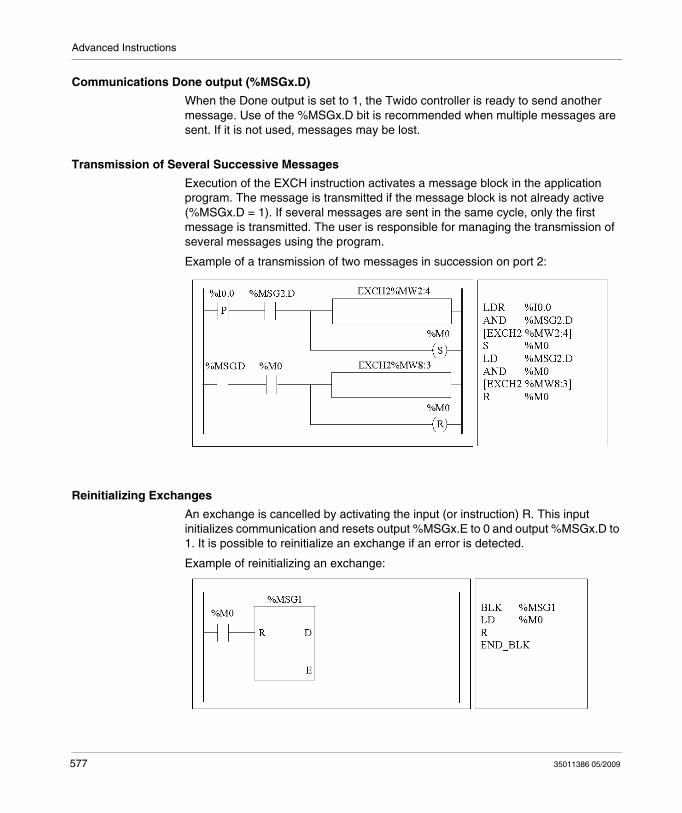
Advanced Instructions
Communications Done output (%MSGx.D)
When the Done output is set to 1, the Twido controller is ready to send another message. Use of the %MSGx.D bit is recommended when multiple messages are sent. If it is not used, messages may be lost.
Transmission of Several Successive Messages
Execution of the EXCH instruction activates a message block in the application program. The message is transmitted if the message block is not already active (%MSGx.D = 1). If several messages are sent in the same cycle, only the first message is transmitted. The user is responsible for managing the transmission of several messages using the program.
Example of a transmission of two messages in succession on port 2:
Reinitializing Exchanges
An exchange is cancelled by activating the input (or instruction) R. This input initializes communication and resets output %MSGx.E to 0 and output %MSGx.D to 1. It is possible to reinitialize an exchange if an error is detected.
Example of reinitializing an exchange:
577 35011386 05/2009

Advanced Instructions
Special Cases
The following table the special operating cases for the %MSGx function block.
Special Case Description
Effect of a cold restart (%S0=1) Forces a reinitialization of the communication.
Effect of a warm restart (%S1=1) Has no effect.
Effect of a controller stop If a message transmission is in progress, the controller stops its transfer and reinitializes the outputs %MSGx.D and %MSGx.E.
35011386 05/2009 578
Advanced Instructions
18.2 Clock Functions
Aim of this Section
This section describes the time management functions for Twido controllers.
What's in this Section?
This section contains the following topics:
Topic Page
Clock Functions 580
Schedule Blocks 581
Time/Date Stamping 584
Setting the Date and Time 586
579 35011386 05/2009
Advanced Instructions
Clock Functions
Introduction
Twido controllers have a time-of-day clock function, which requires the Real-Time Clock option (RTC) and provides the following:
Schedule blocks are used to control actions at predefined or calculated times.Time/date stamping is used to assign time and dates to events and measure event duration.
The Twido time-of-day clock can be accessed by selecting Schedule Blocks from from the TwidoSuite Program → Configure → Configure Data task. Additionally, the time-of-day clock can be set by a program. Clock settings continue to operate for up to 30 days when the controller is switched off, if the battery has been charged for at least six consecutive hours before the controller is switched off.
The time-of-day clock has a 24-hour format and takes leap years into account.
RTC Correction Value
The RTC Correction value is necessary for the correct operation of the RTC. Each RTC unit has its own correction value written on the unit. This value is configurable in TwidoSuite by using the Configure RTC option from the TwidoSuite Monitoring Utility accessible via the TwidoSuite Application Launcher.
35011386 05/2009 580
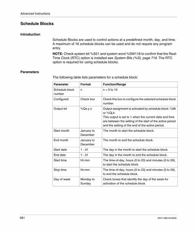
Advanced Instructions
Schedule Blocks
Introduction
Schedule Blocks are used to control actions at a predefined month, day, and time. A maximum of 16 schedule blocks can be used and do not require any program entry.
NOTE: Check system bit %S51 and system word %SW118 to confirm that the Real-Time Clock (RTC) option is installed see System Bits (%S), page 719. The RTC option is required for using schedule blocks.
Parameters
The following table lists parameters for a schedule block:
Parameter Format Function/Range
Schedule block number
n n = 0 to 15
Configured Check box Check this box to configure the selected schedule block number.
Output bit %Qx.y.z Output assignment is activated by schedule block: %Mi or %Qj.k.This output is set to 1 when the current date and time are between the setting of the start of the active period and the setting of the end of the active period.
Start month January to December
The month to start the schedule block.
End month January to December
The month to end the schedule block.
Start date 1 - 31 The day in the month to start the schedule block.
End date 1 - 31 The day in the month to end the schedule block.
Start time hh:mm The time-of-day, hours (0 to 23) and minutes (0 to 59), to start the schedule block.
Stop time hh:mm The time-of-day, hours (0 to 23) and minutes (0 to 59), to end the schedule block.
Day of week Monday to Sunday
Check boxes that identify the day of the week for activation of the schedule block.
581 35011386 05/2009
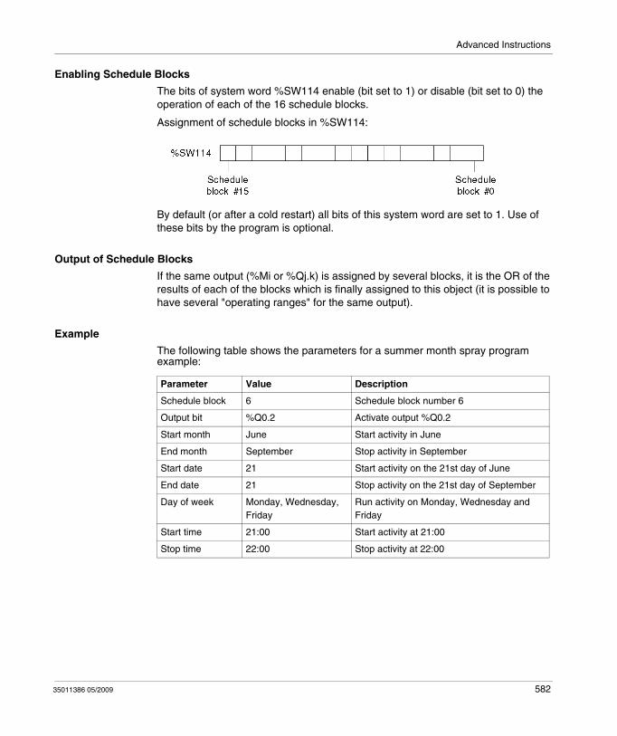
Advanced Instructions
Enabling Schedule Blocks
The bits of system word %SW114 enable (bit set to 1) or disable (bit set to 0) the operation of each of the 16 schedule blocks.
Assignment of schedule blocks in %SW114:
By default (or after a cold restart) all bits of this system word are set to 1. Use of these bits by the program is optional.
Output of Schedule Blocks
If the same output (%Mi or %Qj.k) is assigned by several blocks, it is the OR of the results of each of the blocks which is finally assigned to this object (it is possible to have several "operating ranges" for the same output).
Example
The following table shows the parameters for a summer month spray program example:
Parameter Value Description
Schedule block 6 Schedule block number 6
Output bit %Q0.2 Activate output %Q0.2
Start month June Start activity in June
End month September Stop activity in September
Start date 21 Start activity on the 21st day of June
End date 21 Stop activity on the 21st day of September
Day of week Monday, Wednesday, Friday
Run activity on Monday, Wednesday and Friday
Start time 21:00 Start activity at 21:00
Stop time 22:00 Stop activity at 22:00
35011386 05/2009 582
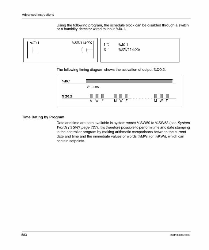
Advanced Instructions
Using the following program, the schedule block can be disabled through a switch or a humidity detector wired to input %I0.1.
The following timing diagram shows the activation of output %Q0.2.
Time Dating by Program
Date and time are both available in system words %SW50 to %SW53 (see System Words (%SW), page 727). It is therefore possible to perform time and date stamping in the controller program by making arithmetic comparisons between the current date and time and the immediate values or words %MWi (or %KWi), which can contain setpoints.
583 35011386 05/2009
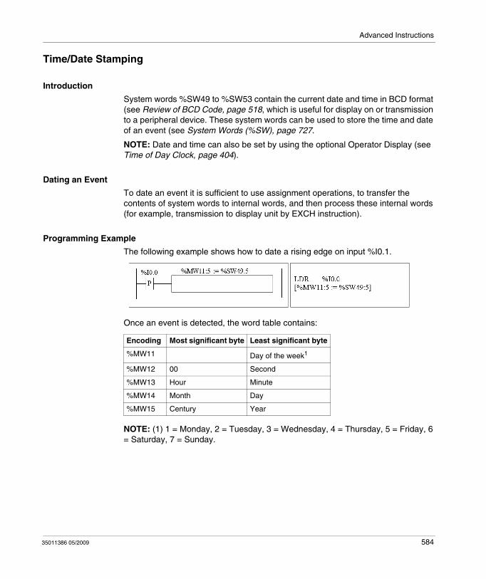
Advanced Instructions
Time/Date Stamping
Introduction
System words %SW49 to %SW53 contain the current date and time in BCD format (see Review of BCD Code, page 518, which is useful for display on or transmission to a peripheral device. These system words can be used to store the time and date of an event (see System Words (%SW), page 727.
NOTE: Date and time can also be set by using the optional Operator Display (see Time of Day Clock, page 404).
Dating an Event
To date an event it is sufficient to use assignment operations, to transfer the contents of system words to internal words, and then process these internal words (for example, transmission to display unit by EXCH instruction).
Programming Example
The following example shows how to date a rising edge on input %I0.1.
Once an event is detected, the word table contains:
NOTE: (1) 1 = Monday, 2 = Tuesday, 3 = Wednesday, 4 = Thursday, 5 = Friday, 6 = Saturday, 7 = Sunday.
Encoding Most significant byte Least significant byte
%MW11 Day of the week1
%MW12 00 Second
%MW13 Hour Minute
%MW14 Month Day
%MW15 Century Year
35011386 05/2009 584
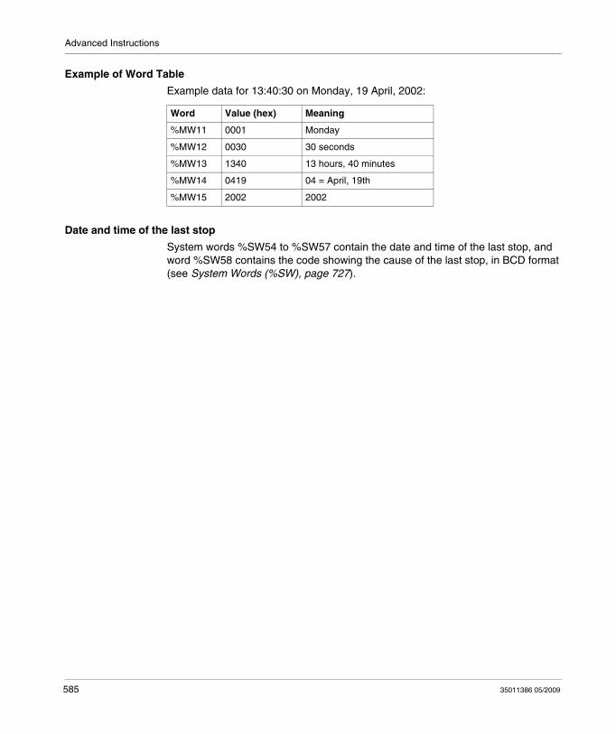
Advanced Instructions
Example of Word Table
Example data for 13:40:30 on Monday, 19 April, 2002:
Date and time of the last stop
System words %SW54 to %SW57 contain the date and time of the last stop, and word %SW58 contains the code showing the cause of the last stop, in BCD format (see System Words (%SW), page 727).
Word Value (hex) Meaning
%MW11 0001 Monday
%MW12 0030 30 seconds
%MW13 1340 13 hours, 40 minutes
%MW14 0419 04 = April, 19th
%MW15 2002 2002
585 35011386 05/2009
Advanced Instructions
Setting the Date and Time
Introduction
You can update the date and time settings by using one of the following methods:
TwidoSuiteUse the Adjust Time dialog box. This dialog box is available from either
the TwidoSuite Monitoring Utility accessible via the TwidoSuite Application Launcher orby selecting Program → Debug, connecting yourself and selecting Check PLC.
System WordsUse system words %SW49 to %SW53 or system word %SW59.
The date and time settings can only be updated when the RTC option cartridge (TWDXCPRTC) is installed on the controller. Note that the TWDLC••40DRF series of compact controllers and the Twido Extreme TWDLEDCK1 PLC have an integrated RTC onboard.
Using %SW49 to %SW53
To use system words %SW49 to %SW53 to set the date and time, bit %S50 must be set to 1. This results in the following:
Cancels the update of words %SW49 to %SW53 via the internal clock.Transmits the values written in words %SW49 to %SW53 to the internal clock.
35011386 05/2009 586
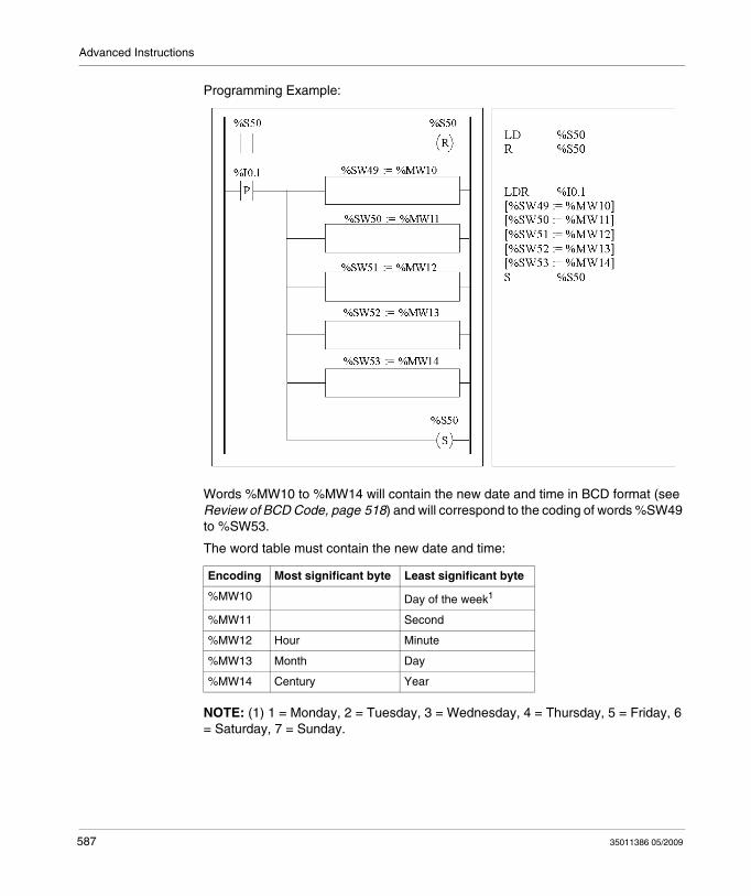
Advanced Instructions
Programming Example:
Words %MW10 to %MW14 will contain the new date and time in BCD format (see Review of BCD Code, page 518) and will correspond to the coding of words %SW49 to %SW53.
The word table must contain the new date and time:
NOTE: (1) 1 = Monday, 2 = Tuesday, 3 = Wednesday, 4 = Thursday, 5 = Friday, 6 = Saturday, 7 = Sunday.
Encoding Most significant byte Least significant byte
%MW10 Day of the week1
%MW11 Second
%MW12 Hour Minute
%MW13 Month Day
%MW14 Century Year
587 35011386 05/2009
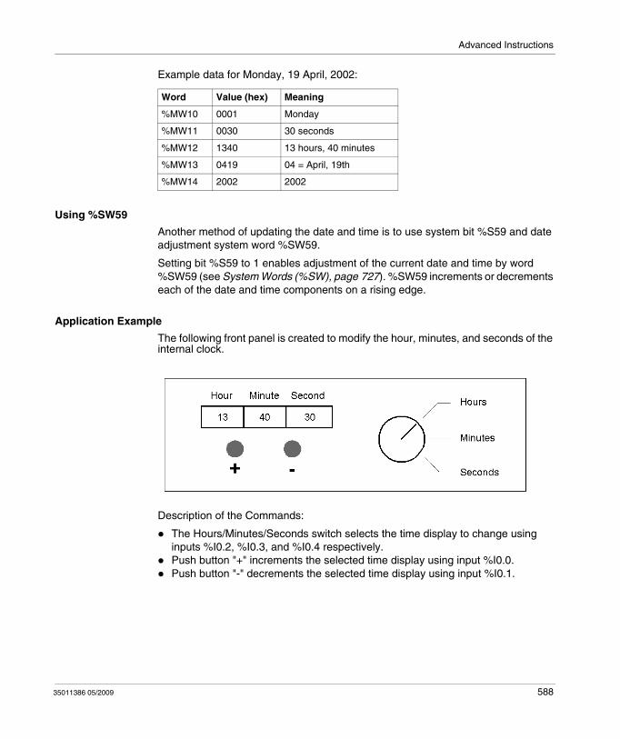
Advanced Instructions
Example data for Monday, 19 April, 2002:
Using %SW59
Another method of updating the date and time is to use system bit %S59 and date adjustment system word %SW59.
Setting bit %S59 to 1 enables adjustment of the current date and time by word %SW59 (see System Words (%SW), page 727). %SW59 increments or decrements each of the date and time components on a rising edge.
Application Example
The following front panel is created to modify the hour, minutes, and seconds of the internal clock.
Description of the Commands:
The Hours/Minutes/Seconds switch selects the time display to change using inputs %I0.2, %I0.3, and %I0.4 respectively.Push button "+" increments the selected time display using input %I0.0.Push button "-" decrements the selected time display using input %I0.1.
Word Value (hex) Meaning
%MW10 0001 Monday
%MW11 0030 30 seconds
%MW12 1340 13 hours, 40 minutes
%MW13 0419 04 = April, 19th
%MW14 2002 2002
35011386 05/2009 588
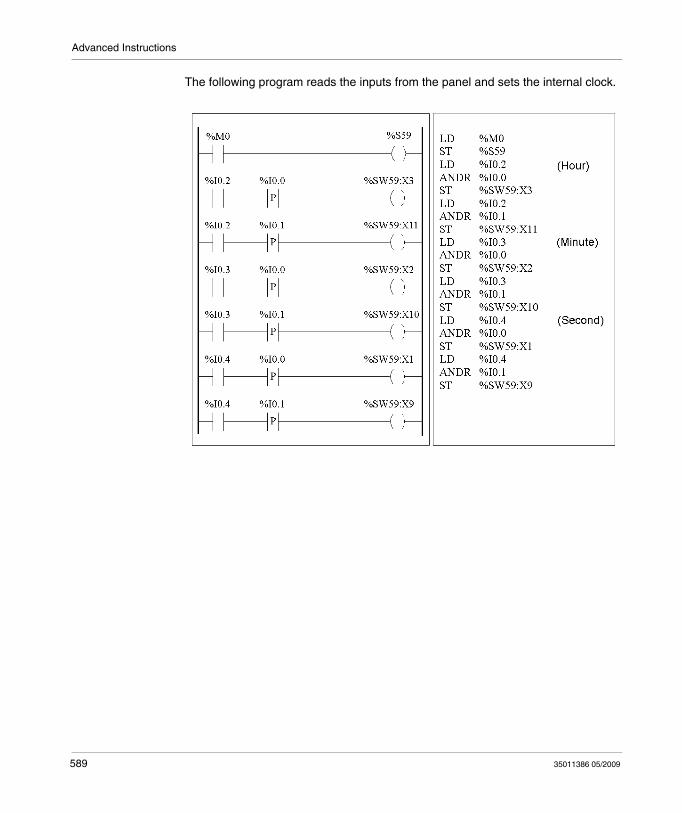
Advanced Instructions
The following program reads the inputs from the panel and sets the internal clock.
589 35011386 05/2009
Advanced Instructions
18.3 Twido PID Quick Start Guide
Overview
This section contains information for getting started with the PID control and Auto-Tuning functions available on Twido controllers.
What's in this Section?
This section contains the following topics:
Topic Page
Purpose of Document 591
Step 1 - Configuration of Analog Channels Used for Control 593
Step 2 - Prerequisites for PID Configuration 595
Step 3 – Configuring the PID 597
Step 4 - Initialization of Control Set-Up 603
Step 5 - Control Set-Up AT + PID 608
Step 6 - Debugging Adjustments 612
35011386 05/2009 590

Advanced Instructions
Purpose of Document
Introduction
This quick start guide aims to guide you, by providing examples, through all the steps required to correctly configure and set up your Twido controller's PID control functions.
NOTE: Implementing the PID function on a Twido does not require an advanced level of system understanding, but does demand a certain degree of rigor for good results.
This document contains:
This document explains the following steps:
Concerning the example used in this guide
For this example, we have chosen a Type K ThermoCouple (0-200°).
We will use transistor control with the output therefore being a base controller output controlled directly by the PID controller using PWM (see Step 3 – Configuring the PID, page 597
Step Description
1 Configuration of analog channels used for control
2 Prerequisites for PID configuration
3 PID configuration
4 Initialization of control setup.
5 AT + PID control setup
6 Debugging and adjustments
591 35011386 05/2009
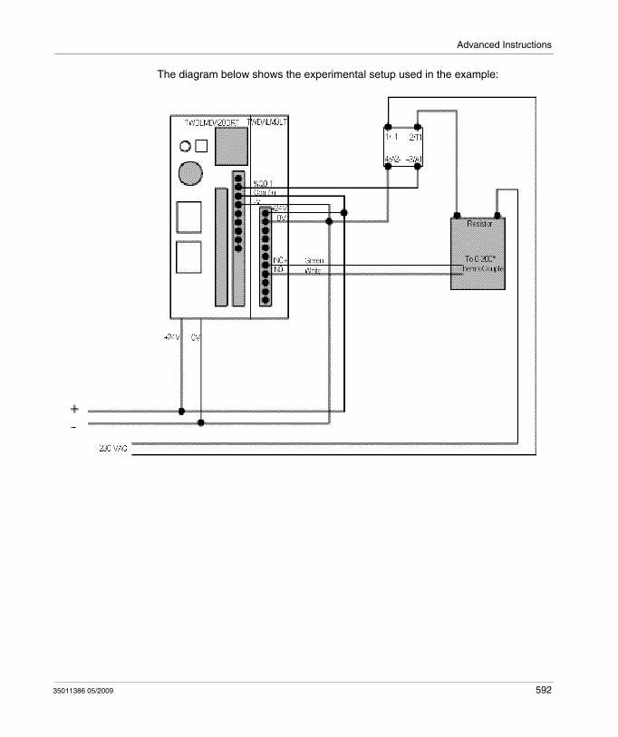
Advanced Instructions
The diagram below shows the experimental setup used in the example:
35011386 05/2009 592
Advanced Instructions
Step 1 - Configuration of Analog Channels Used for Control
Introduction
In general, a PID controller uses an analog feedback signal (known as the "process value") to measure the value to be adjusted.
This value can be a level, a temperature, a distance, or another value for other applications.
Example of an Analog Measurement Signal
Let us take the example of a temperature measurement.
The sensor sends an analog measurement which depends on the measured value back to the controller. For temperature and with sensors such as PT100s or Thermocouples, the measured signal increases with an increase in current temperature.
How to Add an Analog Card (Expansion Module)
In offline mode, once you have selected the base controller, add the analog card as a base extension. The numbering of the channels will depend on its configuration slot.
How to Configure Analog Input Channels
The following table describes the procedure for configuring the analog channels of the expansion module:
Step Action
1 Select Describe step from the TwidoSuite interface.See .
2 Display the product catalog and select a module to add to the system description.For example, TWDALM3LT for measuring temperature using a PT100 or Thermocouple.
3 Add the module to the system description (see .)
4 Use the Configuration Editor to set parameters of analog I/O modules that you added as expansion modules when you described the system.
5 In the Type column, select the input type corresponding to the type of sensor used (ThermoCouple K, if the sensor is of this type).
6 In the Range column, select the measurement unit for the sensor. For temperature sensors it is easier to select Celsius, as this makes the number of counts sent back by the analog card a direct factor of the real measurement.
593 35011386 05/2009
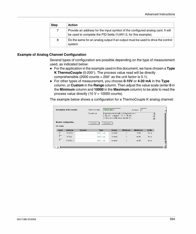
Advanced Instructions
Example of Analog Channel Configuration
Several types of configuration are possible depending on the type of measurement used, as indicated below:
For the application in the example used in this document, we have chosen a Type K ThermoCouple (0-200°). The process value read will be directly comprehensible (2000 counts = 200° as the unit factor is 0.1).For other types of measurement, you choose 0-10V or 4-20 mA in the Type column, or Custom in the Range column. Then adjust the value scale (enter 0 in the Minimum column and 10000 in the Maximum column) to be able to read the process value directly (10 V = 10000 counts).
The example below shows a configuration for a ThermoCouple K analog channel:
7 Provide an address for the input symbol of the configured analog card. It will be used to complete the PID fields (%IW1.0, for this example).
8 Do the same for an analog output if an output must be used to drive the control system.
Step Action
35011386 05/2009 594
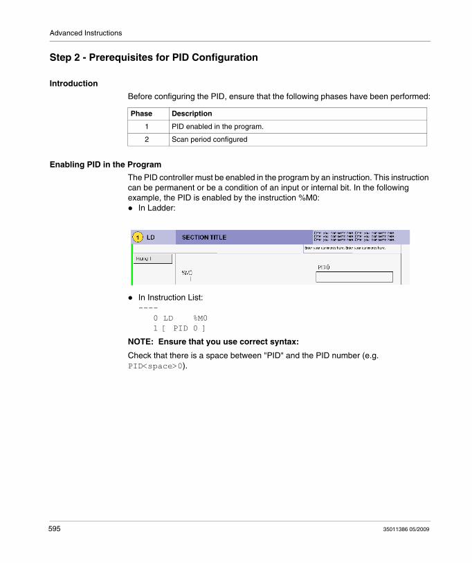
Advanced Instructions
Step 2 - Prerequisites for PID Configuration
Introduction
Before configuring the PID, ensure that the following phases have been performed:
Enabling PID in the Program
The PID controller must be enabled in the program by an instruction. This instruction can be permanent or be a condition of an input or internal bit. In the following example, the PID is enabled by the instruction %M0:
In Ladder:
In Instruction List:---- 0 LD %M0 1 [ PID 0 ]
NOTE: Ensure that you use correct syntax:
Check that there is a space between "PID" and the PID number (e.g. PID<space>0).
Phase Description
1 PID enabled in the program.
2 Scan period configured
595 35011386 05/2009
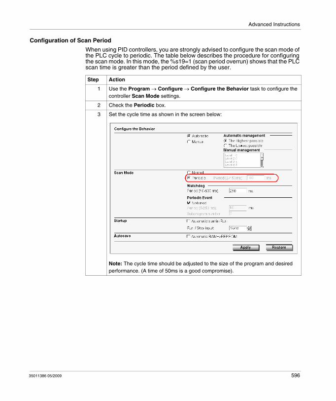
Advanced Instructions
Configuration of Scan Period
When using PID controllers, you are strongly advised to configure the scan mode of the PLC cycle to periodic. The table below describes the procedure for configuring the scan mode. In this mode, the %s19=1 (scan period overrun) shows that the PLC scan time is greater than the period defined by the user.
Step Action
1 Use the Program → Configure → Configure the Behavior task to configure the controller Scan Mode settings.
2 Check the Periodic box.
3 Set the cycle time as shown in the screen below:
Note: The cycle time should be adjusted to the size of the program and desired performance. (A time of 50ms is a good compromise).
35011386 05/2009 596
Advanced Instructions
Step 3 – Configuring the PID
Introduction
For this example, we have chosen to implement the majority of PID controller functions for Twido. Some selections are not essential and can be simplified.
Auto-Tuning (AT)
The PID controller has an Auto-Tuning function that simplifies the regulation loop setting (this function is referred to as AT in the rest of the document).
Operating Modes
The Twido PID controller offers four distinct operating modes, configurable in the General tab in the PID dialog box:
PID = Simple PID controller.AT + PID = The Auto-Tuning function is active when the PID starts up and automatically enters the gain values Kp, Ti, Td (PID tab) and the type of PID action (Output tab). At the end of the Auto-Tuning, sequence, the controller switches to PID mode for the adjusted setpoint, and using the parameters set by AT.AT = The Auto-Tuning function is active when the PID starts up and automatically enters the gain values Kp, Ti, Td (PID tab) and the type of PID action (Output tab). At the end of the sequence the PID stops and waits. The gain values Kp, Ti, Td (PID tab) and the type of PID action (Output tab) are entered.Word address = The selection of PID operating mode can be controlled by the program by assigning the desired value to the word address associated to this selection:
%MWxx=1: The controller operates in simple PID mode.%MWxx=2: The controller operates in AT + PID.%MWxx=3: The controller operates in AT mode only.%MWxx=4: The controller operates in PI mode only.
This type of configuration via the word address enables the user to manage the PID controller operating mode via the application program, thus making it possible to adapt to the final requirements.
NOTE: PI regulation can be selected from the PID tab.
597 35011386 05/2009
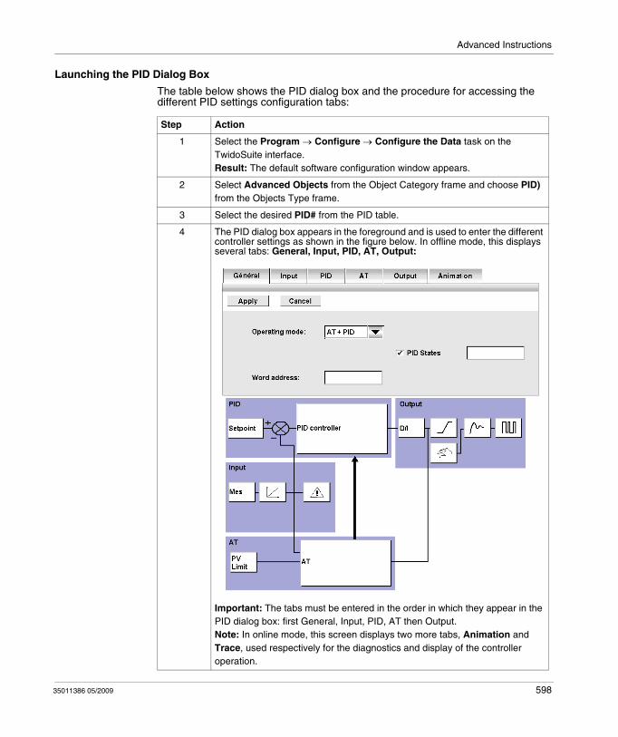
Advanced Instructions
Launching the PID Dialog Box
The table below shows the PID dialog box and the procedure for accessing the different PID settings configuration tabs:
Step Action
1 Select the Program → Configure → Configure the Data task on the TwidoSuite interface.Result: The default software configuration window appears.
2 Select Advanced Objects from the Object Category frame and choose PID) from the Objects Type frame.
3 Select the desired PID# from the PID table.
4 The PID dialog box appears in the foreground and is used to enter the different controller settings as shown in the figure below. In offline mode, this displays several tabs: General, Input, PID, AT, Output:
Important: The tabs must be entered in the order in which they appear in the PID dialog box: first General, Input, PID, AT then Output.Note: In online mode, this screen displays two more tabs, Animation and Trace, used respectively for the diagnostics and display of the controller operation.
35011386 05/2009 598
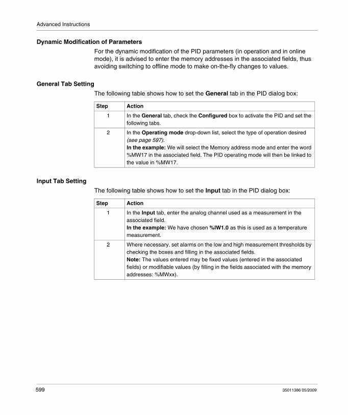
Advanced Instructions
Dynamic Modification of Parameters
For the dynamic modification of the PID parameters (in operation and in online mode), it is advised to enter the memory addresses in the associated fields, thus avoiding switching to offline mode to make on-the-fly changes to values.
General Tab Setting
The following table shows how to set the General tab in the PID dialog box:
Input Tab Setting
The following table shows how to set the Input tab in the PID dialog box:
Step Action
1 In the General tab, check the Configured box to activate the PID and set the following tabs.
2 In the Operating mode drop-down list, select the type of operation desired (see page 597).In the example: We will select the Memory address mode and enter the word %MW17 in the associated field. The PID operating mode will then be linked to the value in %MW17.
Step Action
1 In the Input tab, enter the analog channel used as a measurement in the associated field.In the example: We have chosen %IW1.0 as this is used as a temperature measurement.
2 Where necessary, set alarms on the low and high measurement thresholds by checking the boxes and filling in the associated fields.Note: The values entered may be fixed values (entered in the associated fields) or modifiable values (by filling in the fields associated with the memory addresses: %MWxx).
599 35011386 05/2009
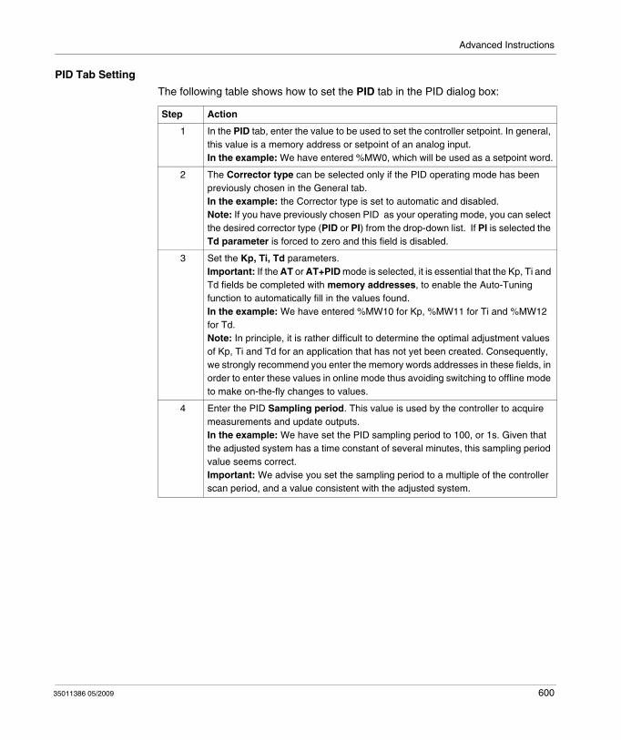
Advanced Instructions
PID Tab Setting
The following table shows how to set the PID tab in the PID dialog box:
Step Action
1 In the PID tab, enter the value to be used to set the controller setpoint. In general, this value is a memory address or setpoint of an analog input. In the example: We have entered %MW0, which will be used as a setpoint word.
2 The Corrector type can be selected only if the PID operating mode has been previously chosen in the General tab.In the example: the Corrector type is set to automatic and disabled.Note: If you have previously chosen PID as your operating mode, you can select the desired corrector type (PID or PI) from the drop-down list. If PI is selected the Td parameter is forced to zero and this field is disabled.
3 Set the Kp, Ti, Td parameters.Important: If the AT or AT+PID mode is selected, it is essential that the Kp, Ti and Td fields be completed with memory addresses, to enable the Auto-Tuning function to automatically fill in the values found.In the example: We have entered %MW10 for Kp, %MW11 for Ti and %MW12 for Td.Note: In principle, it is rather difficult to determine the optimal adjustment values of Kp, Ti and Td for an application that has not yet been created. Consequently, we strongly recommend you enter the memory words addresses in these fields, in order to enter these values in online mode thus avoiding switching to offline mode to make on-the-fly changes to values.
4 Enter the PID Sampling period. This value is used by the controller to acquire measurements and update outputs.In the example: We have set the PID sampling period to 100, or 1s. Given that the adjusted system has a time constant of several minutes, this sampling period value seems correct.Important: We advise you set the sampling period to a multiple of the controller scan period, and a value consistent with the adjusted system.
35011386 05/2009 600
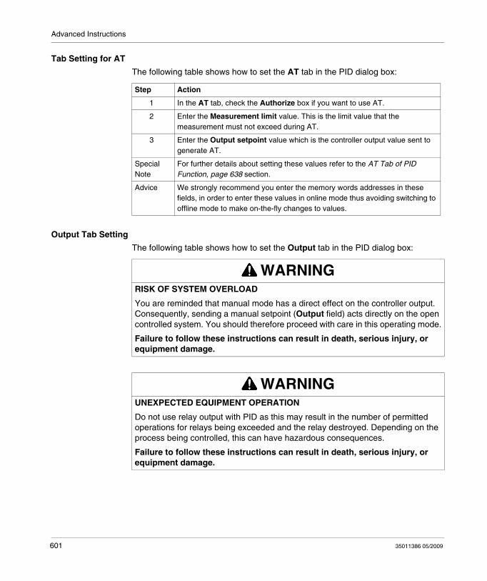
Advanced Instructions
Tab Setting for AT
The following table shows how to set the AT tab in the PID dialog box:
Output Tab Setting
The following table shows how to set the Output tab in the PID dialog box:
Step Action
1 In the AT tab, check the Authorize box if you want to use AT.
2 Enter the Measurement limit value. This is the limit value that the measurement must not exceed during AT.
3 Enter the Output setpoint value which is the controller output value sent to generate AT.
Special Note
For further details about setting these values refer to the AT Tab of PID Function, page 638 section.
Advice We strongly recommend you enter the memory words addresses in these fields, in order to enter these values in online mode thus avoiding switching to offline mode to make on-the-fly changes to values.
WARNINGRISK OF SYSTEM OVERLOAD
You are reminded that manual mode has a direct effect on the controller output. Consequently, sending a manual setpoint (Output field) acts directly on the open controlled system. You should therefore proceed with care in this operating mode.
Failure to follow these instructions can result in death, serious injury, or equipment damage.
WARNINGUNEXPECTED EQUIPMENT OPERATION
Do not use relay output with PID as this may result in the number of permitted operations for relays being exceeded and the relay destroyed. Depending on the process being controlled, this can have hazardous consequences.
Failure to follow these instructions can result in death, serious injury, or equipment damage.
601 35011386 05/2009
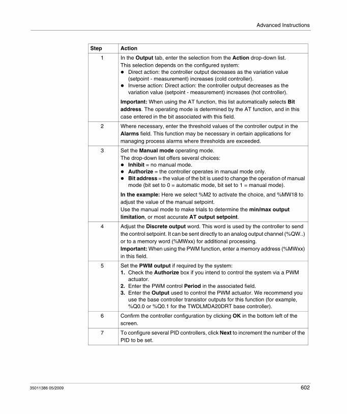
Advanced Instructions
Step Action
1 In the Output tab, enter the selection from the Action drop-down list.This selection depends on the configured system:
Direct action: the controller output decreases as the variation value (setpoint - measurement) increases (cold controller).Inverse action: Direct action: the controller output decreases as the variation value (setpoint - measurement) increases (hot controller).
Important: When using the AT function, this list automatically selects Bit address. The operating mode is determined by the AT function, and in this case entered in the bit associated with this field.
2 Where necessary, enter the threshold values of the controller output in the Alarms field. This function may be necessary in certain applications for managing process alarms where thresholds are exceeded.
3 Set the Manual mode operating mode.The drop-down list offers several choices:
Inhibit = no manual mode.Authorize = the controller operates in manual mode only.Bit address = the value of the bit is used to change the operation of manual mode (bit set to 0 = automatic mode, bit set to 1 = manual mode).
In the example: Here we select %M2 to activate the choice, and %MW18 to adjust the value of the manual setpoint.Use the manual mode to make trials to determine the min/max output limitation, or most accurate AT output setpoint.
4 Adjust the Discrete output word. This word is used by the controller to send the control setpoint. It can be sent directly to an analog output channel (%QW..) or to a memory word (%MWxx) for additional processing.Important: When using the PWM function, enter a memory address (%MWxx) in this field.
5 Set the PWM output if required by the system:1. Check the Authorize box if you intend to control the system via a PWM
actuator.2. Enter the PWM control Period in the associated field.3. Enter the Output used to control the PWM actuator. We recommend you
use the base controller transistor outputs for this function (for example, %Q0.0 or %Q0.1 for the TWDLMDA20DRT base controller).
6 Confirm the controller configuration by clicking OK in the bottom left of the screen.
7 To configure several PID controllers, click Next to increment the number of the PID to be set.
35011386 05/2009 602
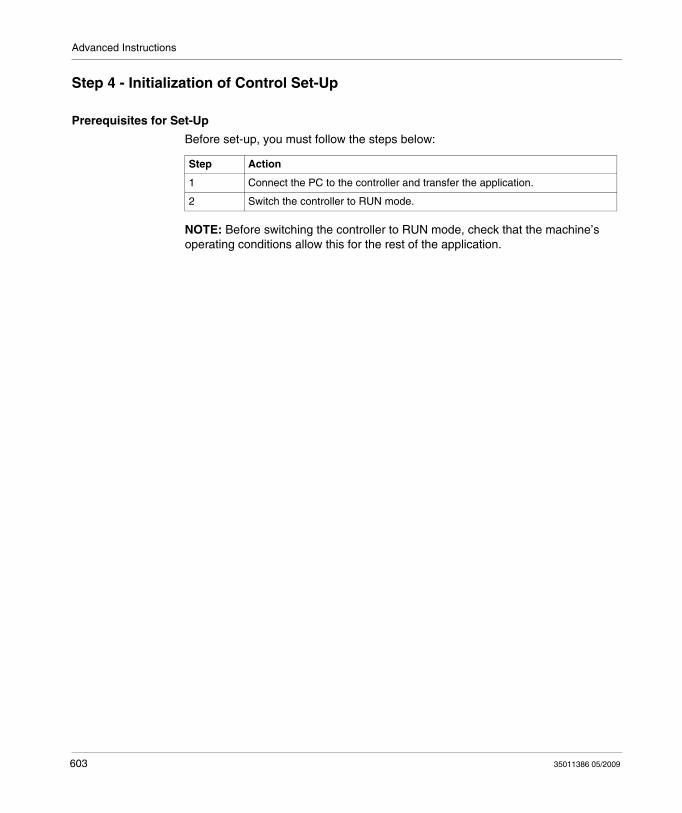
Advanced Instructions
Step 4 - Initialization of Control Set-Up
Prerequisites for Set-Up
Before set-up, you must follow the steps below:
NOTE: Before switching the controller to RUN mode, check that the machine’s operating conditions allow this for the rest of the application.
Step Action
1 Connect the PC to the controller and transfer the application.
2 Switch the controller to RUN mode.
603 35011386 05/2009
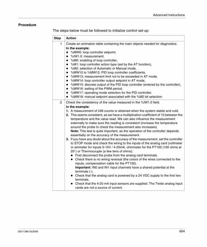
Advanced Instructions
Procedure
The steps below must be followed to initialize control set-up:
Step Action
1 Create an animation table containing the main objects needed for diagnostics.In the example:
%MW0: loop controller setpoint,%IW1.0: measurement,%M0: enabling of loop controller,%M1: loop controller action type (set by the AT function),%M2: selection of Automatic or Manual mode,%MW10 to %MW12: PID loop controller coefficients,%MW13: measurement limit not to be exceeded in AT mode,%MW14: loop controller output setpoint in AT mode,%MW15: discrete output of the PID loop controller (entered by the controller),%MW16: setting of the PWM period,%MW17: operating mode selection for the PID controller,%MW18: manual setpoint associated with the %M2 bit selection.
2 Check the consistency of the value measured in the %IW1.0 field.In the example:1. A measurement of 248 counts is obtained when the system stable and cold.2. This seems consistent, as we have a multiplication coefficient of 10 between the
temperature and the value read. We can also influence the measurement externally to make sure the reading is consistent (increase the temperature around the probe to check the measurement also increases). Note: This test is quite important, as the operation of the controller depends essentially on the accuracy of the measurement.
3. If you have any doubt about the accuracy of the measurement, set the controller to STOP mode and check the wiring to the inputs of the analog card (voltmeter or ammeter for inputs 0-10V / 4-20mA, ohmmeter for the PT100 (100 ohms at 20°) or Thermocouple (a few tens of ohms):
First disconnect the probe from the analog card terminals.Check there is no wiring reversal (the colors of the wires connected to the inputs, compensation cable for the PT100).Important: IN0 and IN1 input channels have a shared potential at the terminals (-).Check that the analog card is powered by a 24 VDC supply to the first two terminals.Check that the 4-20 mA input sensors are supplied. The Twido analog input cards are not a source of current.
35011386 05/2009 604
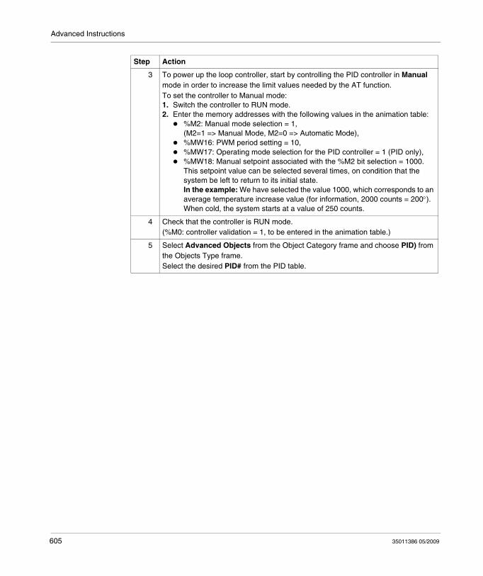
Advanced Instructions
3 To power up the loop controller, start by controlling the PID controller in Manual mode in order to increase the limit values needed by the AT function.To set the controller to Manual mode:1. Switch the controller to RUN mode.2. Enter the memory addresses with the following values in the animation table:
%M2: Manual mode selection = 1, (M2=1 => Manual Mode, M2=0 => Automatic Mode),%MW16: PWM period setting = 10,%MW17: Operating mode selection for the PID controller = 1 (PID only),%MW18: Manual setpoint associated with the %M2 bit selection = 1000.This setpoint value can be selected several times, on condition that the system be left to return to its initial state.In the example: We have selected the value 1000, which corresponds to an average temperature increase value (for information, 2000 counts = 200°). When cold, the system starts at a value of 250 counts.
4 Check that the controller is RUN mode.(%M0: controller validation = 1, to be entered in the animation table.)
5 Select Advanced Objects from the Object Category frame and choose PID) from the Objects Type frame.Select the desired PID# from the PID table.
Step Action
605 35011386 05/2009
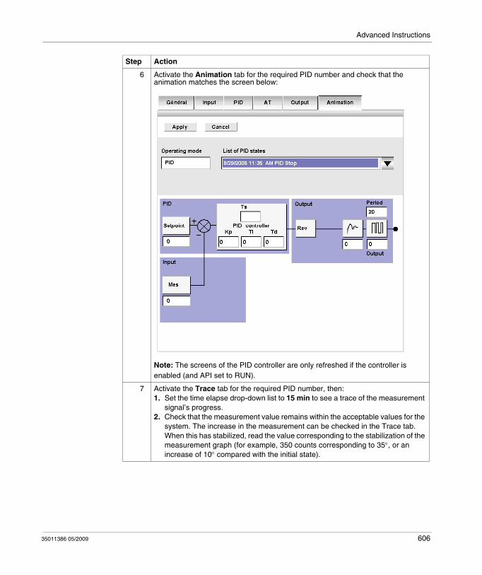
Advanced Instructions
6 Activate the Animation tab for the required PID number and check that the animation matches the screen below:
Note: The screens of the PID controller are only refreshed if the controller is enabled (and API set to RUN).
7 Activate the Trace tab for the required PID number, then:1. Set the time elapse drop-down list to 15 min to see a trace of the measurement
signal’s progress.2. Check that the measurement value remains within the acceptable values for the
system. The increase in the measurement can be checked in the Trace tab. When this has stabilized, read the value corresponding to the stabilization of the measurement graph (for example, 350 counts corresponding to 35°, or an increase of 10° compared with the initial state).
Step Action
35011386 05/2009 606
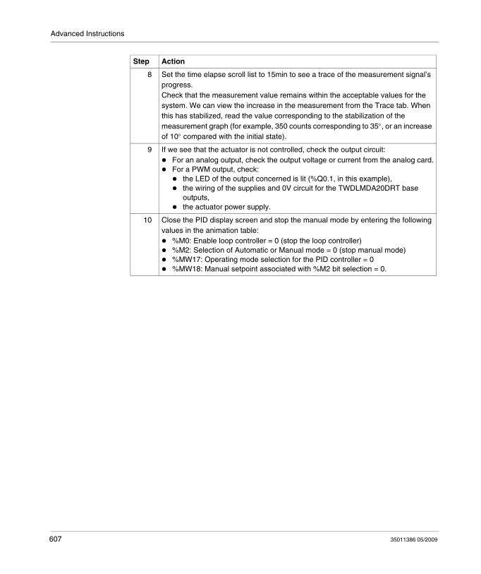
Advanced Instructions
8 Set the time elapse scroll list to 15min to see a trace of the measurement signal’s progress.Check that the measurement value remains within the acceptable values for the system. We can view the increase in the measurement from the Trace tab. When this has stabilized, read the value corresponding to the stabilization of the measurement graph (for example, 350 counts corresponding to 35°, or an increase of 10° compared with the initial state).
9 If we see that the actuator is not controlled, check the output circuit:For an analog output, check the output voltage or current from the analog card.For a PWM output, check:
the LED of the output concerned is lit (%Q0.1, in this example),the wiring of the supplies and 0V circuit for the TWDLMDA20DRT base outputs,the actuator power supply.
10 Close the PID display screen and stop the manual mode by entering the following values in the animation table:
%M0: Enable loop controller = 0 (stop the loop controller)%M2: Selection of Automatic or Manual mode = 0 (stop manual mode)%MW17: Operating mode selection for the PID controller = 0%MW18: Manual setpoint associated with %M2 bit selection = 0.
Step Action
607 35011386 05/2009
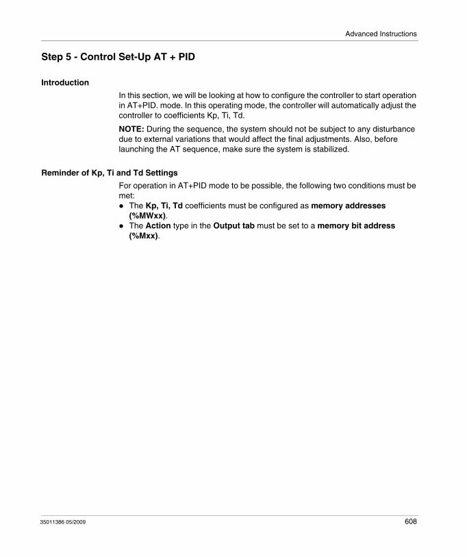
Advanced Instructions
Step 5 - Control Set-Up AT + PID
Introduction
In this section, we will be looking at how to configure the controller to start operation in AT+PID. mode. In this operating mode, the controller will automatically adjust the controller to coefficients Kp, Ti, Td.
NOTE: During the sequence, the system should not be subject to any disturbance due to external variations that would affect the final adjustments. Also, before launching the AT sequence, make sure the system is stabilized.
Reminder of Kp, Ti and Td Settings
For operation in AT+PID mode to be possible, the following two conditions must be met:
The Kp, Ti, Td coefficients must be configured as memory addresses (%MWxx).The Action type in the Output tab must be set to a memory bit address (%Mxx).
35011386 05/2009 608
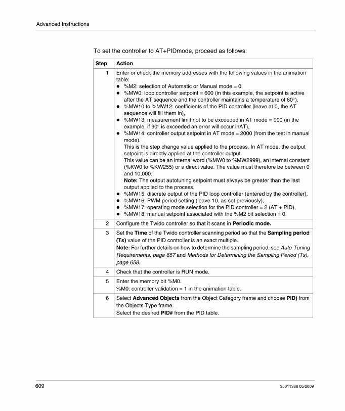
Advanced Instructions
To set the controller to AT+PIDmode, proceed as follows:
Step Action
1 Enter or check the memory addresses with the following values in the animation table:
%M2: selection of Automatic or Manual mode = 0,%MW0: loop controller setpoint = 600 (in this example, the setpoint is active after the AT sequence and the controller maintains a temperature of 60°),%MW10 to %MW12: coefficients of the PID controller (leave at 0, the AT sequence will fill them in),%MW13: measurement limit not to be exceeded in AT mode = 900 (in the example, if 90° is exceeded an error will occur inAT),%MW14: controller output setpoint in AT mode = 2000 (from the test in manual mode). This is the step change value applied to the process. In AT mode, the output setpoint is directly applied at the controller output.This value can be an internal word (%MW0 to %MW2999), an internal constant (%KW0 to %KW255) or a direct value. The value must therefore be between 0 and 10,000.Note: The output autotuning setpoint must always be greater than the last output applied to the process.%MW15: discrete output of the PID loop controller (entered by the controller),%MW16: PWM period setting (leave 10, as set previously),%MW17: operating mode selection for the PID controller = 2 (AT + PID),%MW18: manual setpoint associated with the %M2 bit selection = 0.
2 Configure the Twido controller so that it scans in Periodic mode.
3 Set the Time of the Twido controller scanning period so that the Sampling period (Ts) value of the PID controller is an exact multiple.Note: For further details on how to determine the sampling period, see Auto-Tuning Requirements, page 657 and Methods for Determining the Sampling Period (Ts), page 658.
4 Check that the controller is RUN mode.
5 Enter the memory bit %M0.%M0: controller validation = 1 in the animation table.
6 Select Advanced Objects from the Object Category frame and choose PID) from the Objects Type frame.Select the desired PID# from the PID table.
609 35011386 05/2009
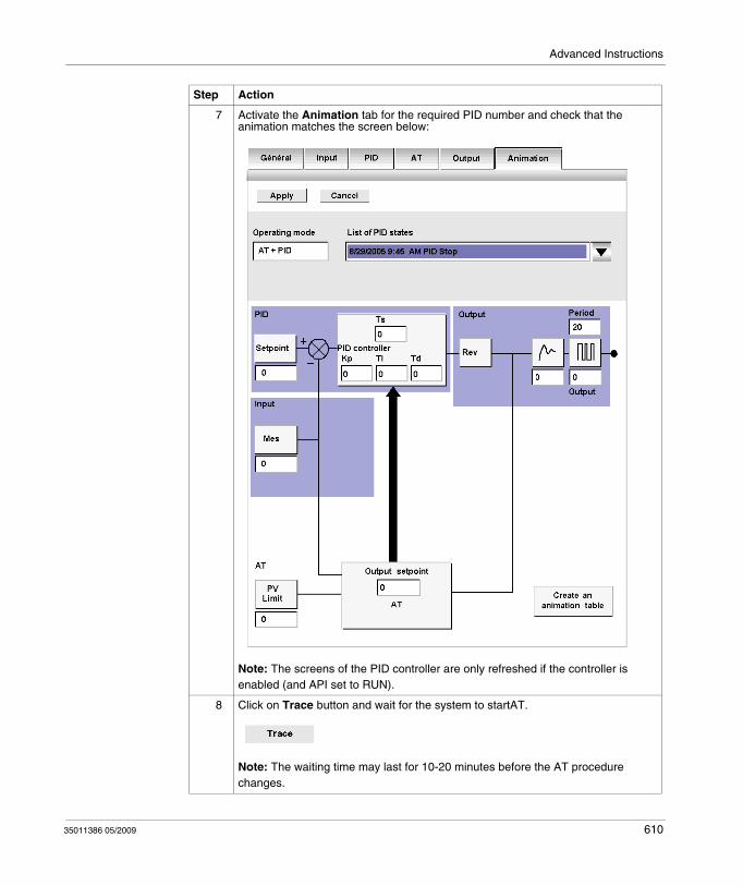
Advanced Instructions
7 Activate the Animation tab for the required PID number and check that the animation matches the screen below:
Note: The screens of the PID controller are only refreshed if the controller is enabled (and API set to RUN).
8 Click on Trace button and wait for the system to startAT.
Note: The waiting time may last for 10-20 minutes before the AT procedure changes.
Step Action
35011386 05/2009 610
Advanced Instructions
Storage of Calculated Kp, Ti and Td Coefficients
Once the Auto-Tuning sequence is complete, the memory words assigned to the Kp, Ti and Td coefficients are completed with the calculated values. These values are written to the RAM memory and saved in the controller as long as the application is valid (power-down of less than 30 days) and no cold-start is performed (%S0).
NOTE: If the system is not influenced by outside fluctuations, the values may be hard written in the settings of the PID controller and the controller switched to PID mode only.
Repetition of AT
The Auto-Tuning sequence is repeated on every switch to RUN or cold start (%S0).
You should therefore test the diagnostics words using the program what to do in the event of a restart.
611 35011386 05/2009
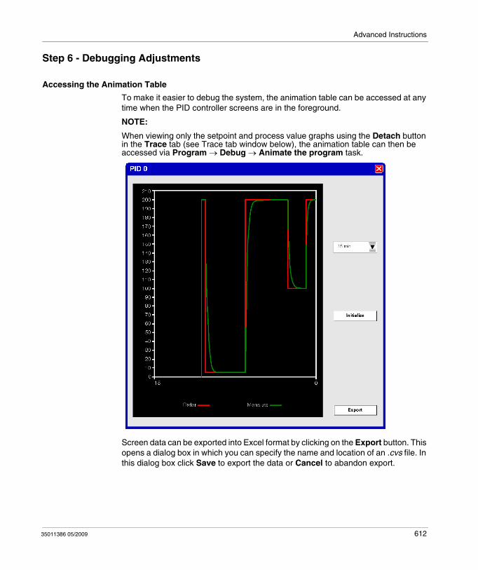
Advanced Instructions
Step 6 - Debugging Adjustments
Accessing the Animation Table
To make it easier to debug the system, the animation table can be accessed at any time when the PID controller screens are in the foreground.
NOTE:
When viewing only the setpoint and process value graphs using the Detach button in the Trace tab (see Trace tab window below), the animation table can then be accessed via Program → Debug → Animate the program task.
Screen data can be exported into Excel format by clicking on the Export button. This opens a dialog box in which you can specify the name and location of an .cvs file. In this dialog box click Save to export the data or Cancel to abandon export.
35011386 05/2009 612
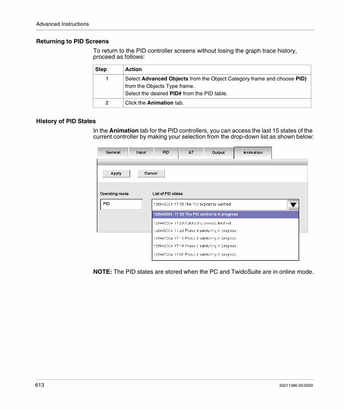
Advanced Instructions
Returning to PID Screens
To return to the PID controller screens without losing the graph trace history, proceed as follows:
History of PID States
In the Animation tab for the PID controllers, you can access the last 15 states of the current controller by making your selection from the drop-down list as shown below:
NOTE: The PID states are stored when the PC and TwidoSuite are in online mode.
Step Action
1 Select Advanced Objects from the Object Category frame and choose PID) from the Objects Type frame.Select the desired PID# from the PID table.
2 Click the Animation tab.
613 35011386 05/2009
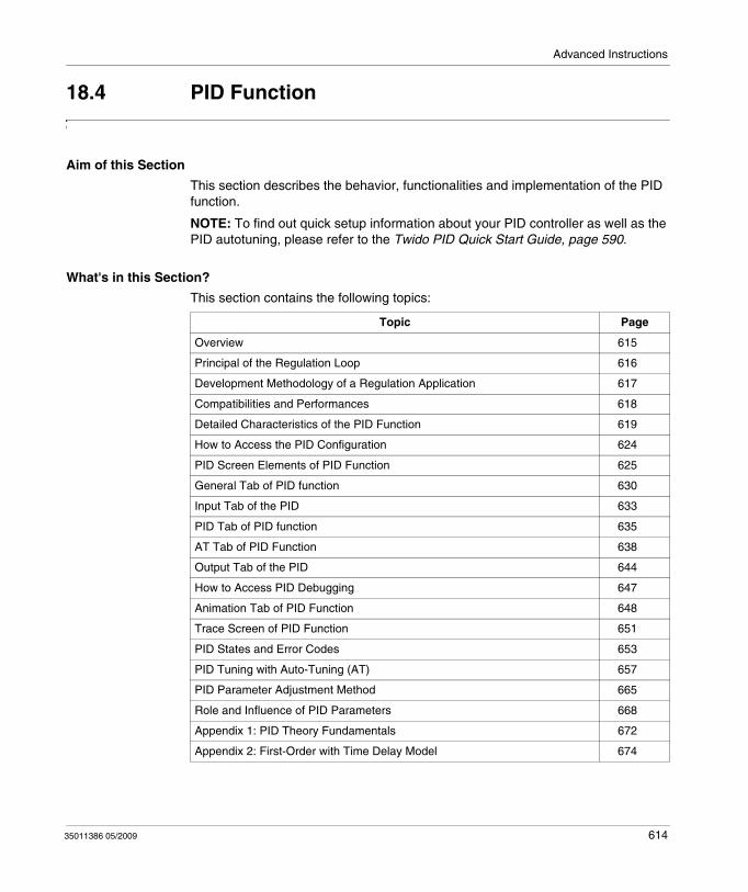
Advanced Instructions
18.4 PID Function
Aim of this Section
This section describes the behavior, functionalities and implementation of the PID function.
NOTE: To find out quick setup information about your PID controller as well as the PID autotuning, please refer to the Twido PID Quick Start Guide, page 590.
What's in this Section?
This section contains the following topics:
Topic Page
Overview 615
Principal of the Regulation Loop 616
Development Methodology of a Regulation Application 617
Compatibilities and Performances 618
Detailed Characteristics of the PID Function 619
How to Access the PID Configuration 624
PID Screen Elements of PID Function 625
General Tab of PID function 630
Input Tab of the PID 633
PID Tab of PID function 635
AT Tab of PID Function 638
Output Tab of the PID 644
How to Access PID Debugging 647
Animation Tab of PID Function 648
Trace Screen of PID Function 651
PID States and Error Codes 653
PID Tuning with Auto-Tuning (AT) 657
PID Parameter Adjustment Method 665
Role and Influence of PID Parameters 668
Appendix 1: PID Theory Fundamentals 672
Appendix 2: First-Order with Time Delay Model 674
35011386 05/2009 614
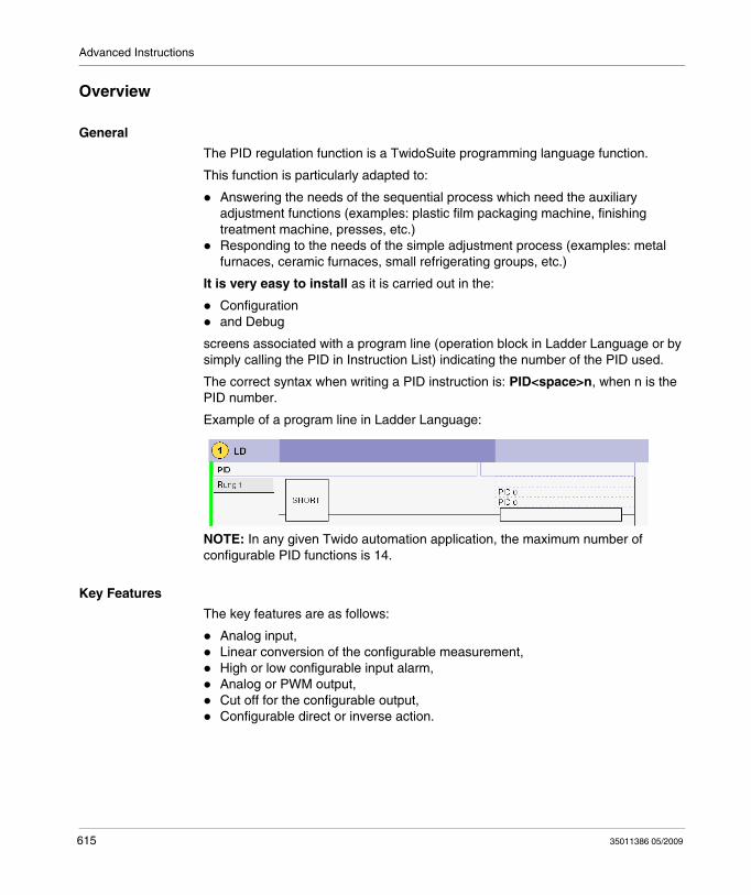
Advanced Instructions
Overview
General
The PID regulation function is a TwidoSuite programming language function.
This function is particularly adapted to:
Answering the needs of the sequential process which need the auxiliary adjustment functions (examples: plastic film packaging machine, finishing treatment machine, presses, etc.)Responding to the needs of the simple adjustment process (examples: metal furnaces, ceramic furnaces, small refrigerating groups, etc.)
It is very easy to install as it is carried out in the:
Configurationand Debug
screens associated with a program line (operation block in Ladder Language or by simply calling the PID in Instruction List) indicating the number of the PID used.
The correct syntax when writing a PID instruction is: PID<space>n, when n is the PID number.
Example of a program line in Ladder Language:
NOTE: In any given Twido automation application, the maximum number of configurable PID functions is 14.
Key Features
The key features are as follows:
Analog input,Linear conversion of the configurable measurement,High or low configurable input alarm,Analog or PWM output,Cut off for the configurable output,Configurable direct or inverse action.
615 35011386 05/2009
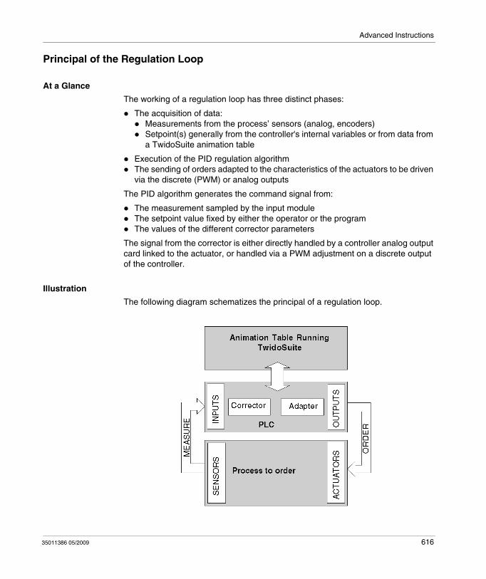
Advanced Instructions
Principal of the Regulation Loop
At a Glance
The working of a regulation loop has three distinct phases:
The acquisition of data:Measurements from the process’ sensors (analog, encoders)Setpoint(s) generally from the controller's internal variables or from data from a TwidoSuite animation table
Execution of the PID regulation algorithmThe sending of orders adapted to the characteristics of the actuators to be driven via the discrete (PWM) or analog outputs
The PID algorithm generates the command signal from:
The measurement sampled by the input module The setpoint value fixed by either the operator or the programThe values of the different corrector parameters
The signal from the corrector is either directly handled by a controller analog output card linked to the actuator, or handled via a PWM adjustment on a discrete output of the controller.
Illustration
The following diagram schematizes the principal of a regulation loop.
35011386 05/2009 616
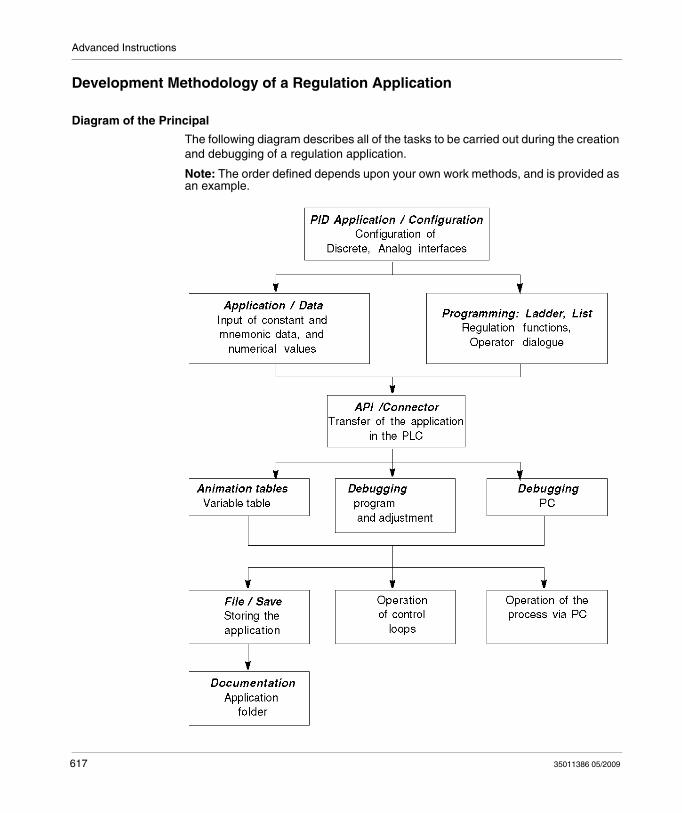
Advanced Instructions
Development Methodology of a Regulation Application
Diagram of the Principal
The following diagram describes all of the tasks to be carried out during the creation and debugging of a regulation application.
Note: The order defined depends upon your own work methods, and is provided as an example.
617 35011386 05/2009
Advanced Instructions
Compatibilities and Performances
At a Glance
The Twido PID function is a function that is available for controllers compatible with Twido version 2.0 or higher, which is why its installation is subject to a number of hardware and software compatibilities described in the following paragraphs.
In addition, this function requires the resources presented in the Performances paragraph.
Compatibility
The Twido PID function is available on Twido controllers version 2.0 or higher software.
If you have Twidos with an earlier version of the software, you can update your firmware in order to use this PID function.
NOTE: The version 1.0 analog input/output modules can be used as PID input/output modules without needing to be updated.
In order to configure and program a PID on these different hardware versions, you must have the TwidoSuite software.
Performance
The PID regulation loops have the following performances:
Description Time
Loop execution time 0.4 ms
35011386 05/2009 618
Advanced Instructions
Detailed Characteristics of the PID Function
General
The PID function completes a PID correction via an analog measurement and setpoint in the default [0-10000] format and provides an analog command in the same format or a Pulse Width Modulation (PWM) on a discrete output.
All the PID parameters are explained in the windows used to configure them. Here, we will simply summarize the functions available, indicate measurement values and describe how they integrate into PID in a functional flow diagram.
NOTE: For use at full scale (best resolution), you can configure your analog input connected to the PID's measurement branch in 0-10000 format. However, if you use the default configuration (0-4095), the controller will function correctly.
NOTE: In order for regulation to operate correctly, it is essential that the Twido PLC is in periodic mode. The PID function is then executed periodically on each cycle, and the PID input data sampling complies with the period set in configuration (see table below).
Details of Available Functions
The following table indicates the different functions available and their scale:
Function Scale and comment
Linear conversion of input Allows you to convert a value in 0 to 10000 format (analog input module resolution) to a value between 32768 and 32767
Proportional gain Using a factor of 100, its value is between 1 and 10000. This corresponds to a gain value varying between 0.01 and 100.Note: If you enter an invalid value of gain (negative or null gain), TwidoSuite ignores this user-setting and automatically assigns the default value of 100 to this factor.
Integral time Using a timebase of 0.1 seconds, its value is between 0 and 20000. This corresponds to an integral time of between 0 and 2000.0 seconds.
Derivative time Using a timebase of 0.1 seconds, its value is between 0 and 10000. This corresponds to a derivative time of between 0 and 1000.0 seconds.
Sampling period Using a timebase of 0.01 seconds, its value is between 1 and 10000. This corresponds to a sampling period of between 0.01 and 100 seconds.
619 35011386 05/2009
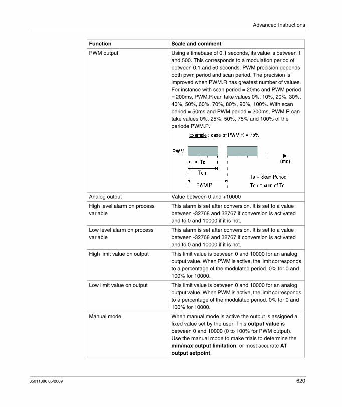
Advanced Instructions
PWM output Using a timebase of 0.1 seconds, its value is between 1 and 500. This corresponds to a modulation period of between 0.1 and 50 seconds. PWM precision depends both pwm period and scan period. The precision is improved when PWM.R has greatest number of values. For instance with scan period = 20ms and PWM period = 200ms, PWM.R can take values 0%, 10%, 20%, 30%, 40%, 50%, 60%, 70%, 80%, 90%, 100%. With scan period = 50ms and PWM period = 200ms, PWM.R can take values 0%, 25%, 50%, 75% and 100% of the periode PWM.P.
Analog output Value between 0 and +10000
High level alarm on process variable
This alarm is set after conversion. It is set to a value between -32768 and 32767 if conversion is activated and to 0 and 10000 if it is not.
Low level alarm on process variable
This alarm is set after conversion. It is set to a value between -32768 and 32767 if conversion is activated and to 0 and 10000 if it is not.
High limit value on output This limit value is between 0 and 10000 for an analog output value. When PWM is active, the limit corresponds to a percentage of the modulated period. 0% for 0 and 100% for 10000.
Low limit value on output This limit value is between 0 and 10000 for an analog output value. When PWM is active, the limit corresponds to a percentage of the modulated period. 0% for 0 and 100% for 10000.
Manual mode When manual mode is active the output is assigned a fixed value set by the user. This output value is between 0 and 10000 (0 to 100% for PWM output).Use the manual mode to make trials to determine the min/max output limitation, or most accurate AT output setpoint.
Function Scale and comment
35011386 05/2009 620

Advanced Instructions
NOTE: For a more in-depth explanation of how each of the functions described in the above table works, refer to the diagram below.
Direct or inverse action Direct or inverse is available and acts directly on the output.
Auto-Tuning (AT) This function provides automatic tuning of the Kp, Ti, Td and Direct/Reverse Action parameters to achieve refined convergence of the PID function.
Function Scale and comment
621 35011386 05/2009
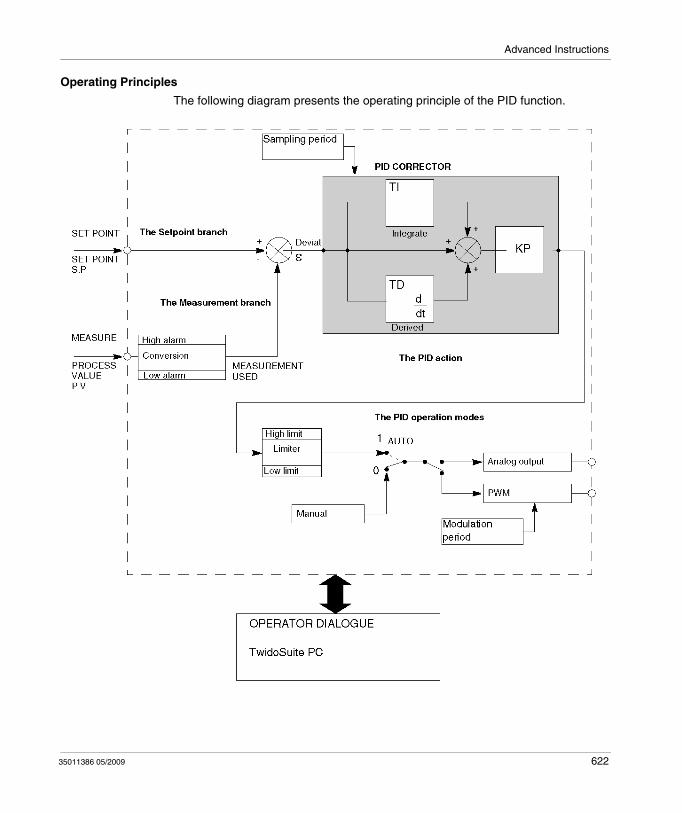
Advanced Instructions
Operating Principles
The following diagram presents the operating principle of the PID function.
35011386 05/2009 622

Advanced Instructions
NOTE: In ONLINE mode, when the PLC is in periodic task, the value displayed in the Ts Field (in the PID software configuration screen) can be different with the parameter entered (%MW). The Ts value is a multiple of the periodic task, whereas the %MW value is the value read by the PLC.
NOTE: The parameters used are described in the table on the page above and in the configuration screens.
623 35011386 05/2009
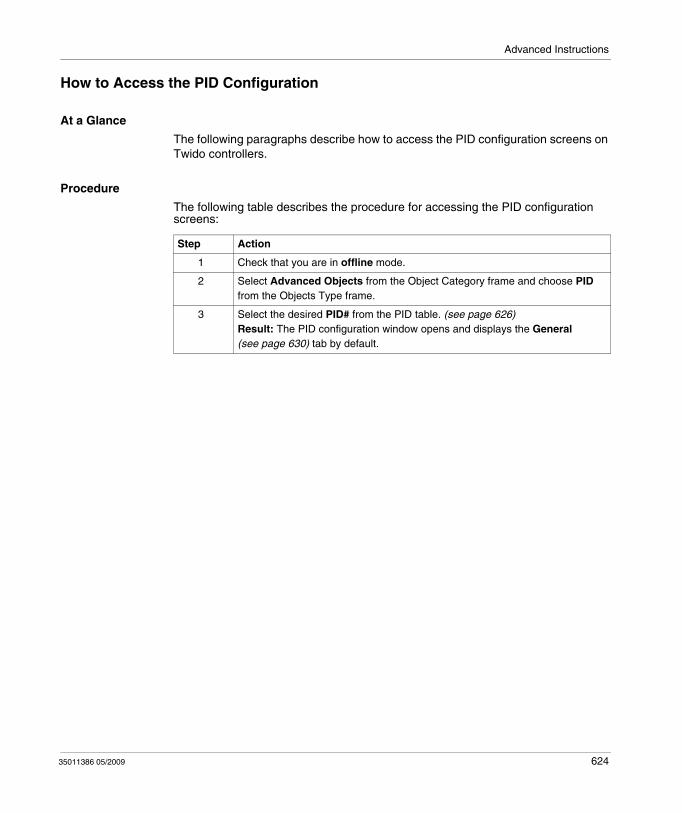
Advanced Instructions
How to Access the PID Configuration
At a Glance
The following paragraphs describe how to access the PID configuration screens on Twido controllers.
Procedure
The following table describes the procedure for accessing the PID configuration screens:
Step Action
1 Check that you are in offline mode.
2 Select Advanced Objects from the Object Category frame and choose PID from the Objects Type frame.
3 Select the desired PID# from the PID table. (see page 626)Result: The PID configuration window opens and displays the General (see page 630) tab by default.
35011386 05/2009 624
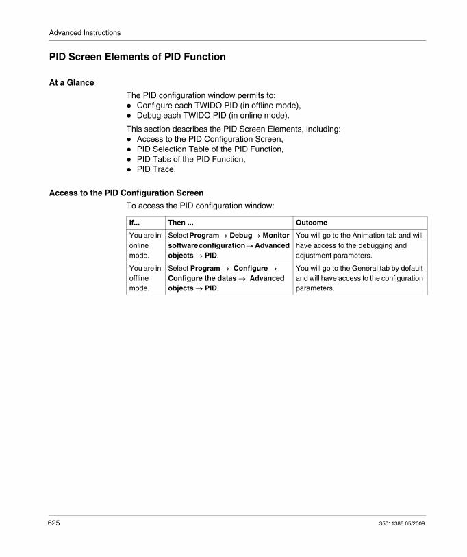
Advanced Instructions
PID Screen Elements of PID Function
At a Glance
The PID configuration window permits to: Configure each TWIDO PID (in offline mode),Debug each TWIDO PID (in online mode).
This section describes the PID Screen Elements, including:Access to the PID Configuration Screen,PID Selection Table of the PID Function,PID Tabs of the PID Function,PID Trace.
Access to the PID Configuration Screen
To access the PID configuration window:
If... Then ... Outcome
You are in online mode.
Select Program → Debug → Monitor software configuration → Advanced objects → PID.
You will go to the Animation tab and will have access to the debugging and adjustment parameters.
You are in offline mode.
Select Program → Configure → Configure the datas → Advanced objects → PID.
You will go to the General tab by default and will have access to the configuration parameters.
625 35011386 05/2009
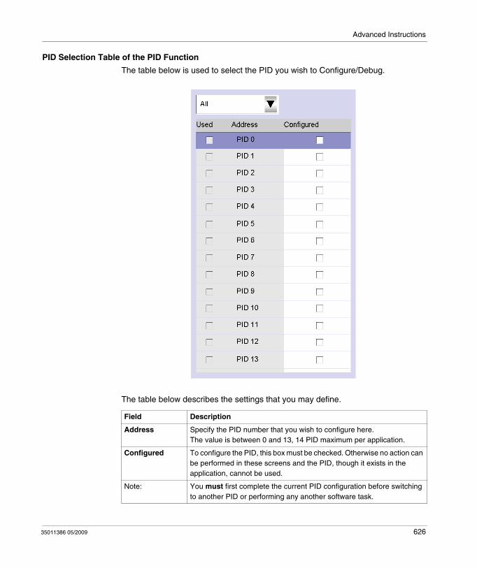
Advanced Instructions
PID Selection Table of the PID Function
The table below is used to select the PID you wish to Configure/Debug.
The table below describes the settings that you may define.
Field Description
Address Specify the PID number that you wish to configure here.The value is between 0 and 13, 14 PID maximum per application.
Configured To configure the PID, this box must be checked. Otherwise no action can be performed in these screens and the PID, though it exists in the application, cannot be used.
Note: You must first complete the current PID configuration before switching to another PID or performing any another software task.
35011386 05/2009 626
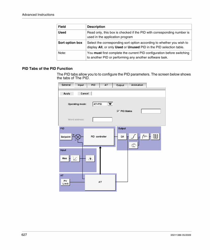
Advanced Instructions
PID Tabs of the PID Function
The PID tabs allow you to to configure the PID parameters. The screen below shows the tabs of The PID.
Used Read only, this box is checked if the PID with corresponding number is used in the application program
Sort option box Select the corresponding sort option according to whether you wish to display All, or only Used or Unused PID in the PID selection table.
Field Description
Note: You must first complete the current PID configuration before switching to another PID or performing any another software task.
627 35011386 05/2009
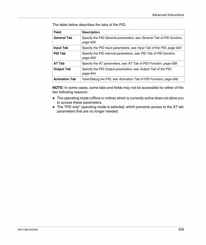
Advanced Instructions
The table below describes the tabs of the PID.
NOTE: In some cases, some tabs and fields may not be accessible for either of the two following reasons:
The operating mode (offline or online) which is currently active does not allow you to access these parameters.The "PID only" operating mode is selected, which prevents access to the AT tab parameters that are no longer needed.
Field Description
General Tab Specify the PID General parameters, see General Tab of PID function, page 630
Input Tab Specify the PID Input parameters, see Input Tab of the PID, page 633
PID Tab Specify the PID internal parameters, see PID Tab of PID function, page 635
AT Tab Specify the AT parameters, see AT Tab of PID Function, page 638
Output Tab Specify the PID Output parameters, see Output Tab of the PID, page 644
Animation Tab View/Debug the PID, see Animation Tab of PID Function, page 648
35011386 05/2009 628
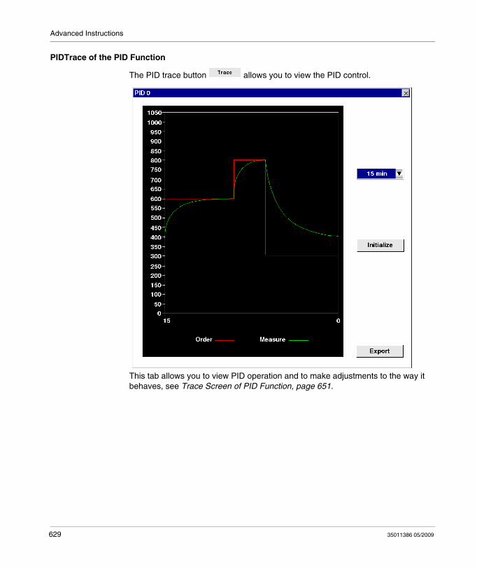
Advanced Instructions
PIDTrace of the PID Function
The PID trace button allows you to view the PID control.
This tab allows you to view PID operation and to make adjustments to the way it behaves, see Trace Screen of PID Function, page 651.
629 35011386 05/2009
Advanced Instructions
General Tab of PID function
At a Glance
Select Advanced Objects from the Object Category frame and choose PID from the Objects Type frame.
Select the desired PID# from the PID table.
The PID configuration window allows you to:
configure each TWIDO PID (in online mode),debug each TWIDO PID (in offline mode),
When you open this screen, if you are:
in offline mode: the General tab is displayed by default and you have access to the configuration parameters,in online mode: the Animation tab is displayed and you have access to the debugging and adjustment parameters.
NOTE: In some cases, some tabs and fields may not be accessible for either of the following reasons:
The operating mode (offline or online) which is currently active does not allow you to access these parameters.The "PID only" operating mode is selected, which prevents access to the AT tab parameters that are no longer needed.
The following paragraphs describe the General tab.
35011386 05/2009 630
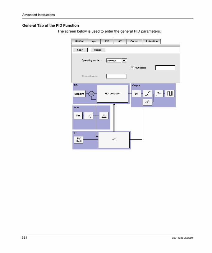
Advanced Instructions
General Tab of the PID Function
The screen below is used to enter the general PID parameters.
631 35011386 05/2009
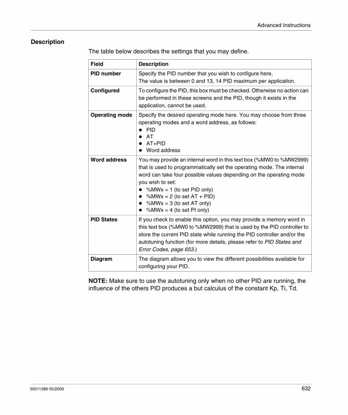
Advanced Instructions
Description
The table below describes the settings that you may define.
NOTE: Make sure to use the autotuning only when no other PID are running, the influence of the others PID produces a but calculus of the constant Kp, Ti, Td.
Field Description
PID number Specify the PID number that you wish to configure here.The value is between 0 and 13, 14 PID maximum per application.
Configured To configure the PID, this box must be checked. Otherwise no action can be performed in these screens and the PID, though it exists in the application, cannot be used.
Operating mode Specify the desired operating mode here. You may choose from three operating modes and a word address, as follows:
PIDATAT+PIDWord address
Word address You may provide an internal word in this text box (%MW0 to %MW2999) that is used to programmatically set the operating mode. The internal word can take four possible values depending on the operating mode you wish to set:
%MWx = 1 (to set PID only)%MWx = 2 (to set AT + PID)%MWx = 3 (to set AT only)%MWx = 4 (to set PI only)
PID States If you check to enable this option, you may provide a memory word in this text box (%MW0 to %MW2999) that is used by the PID controller to store the current PID state while running the PID controller and/or the autotuning function (for more details, please refer to PID States and Error Codes, page 653.)
Diagram The diagram allows you to view the different possibilities available for configuring your PID.
35011386 05/2009 632
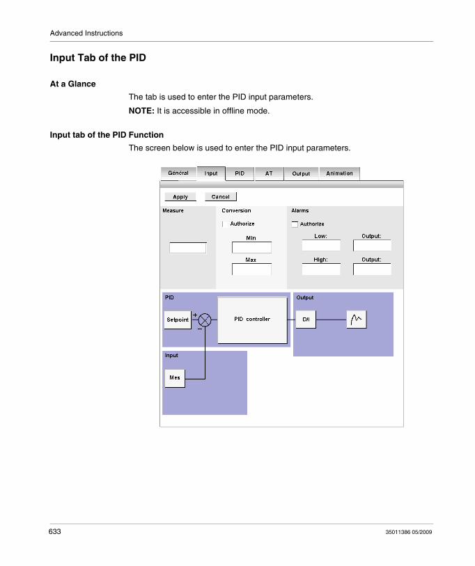
Advanced Instructions
Input Tab of the PID
At a Glance
The tab is used to enter the PID input parameters.
NOTE: It is accessible in offline mode.
Input tab of the PID Function
The screen below is used to enter the PID input parameters.
633 35011386 05/2009
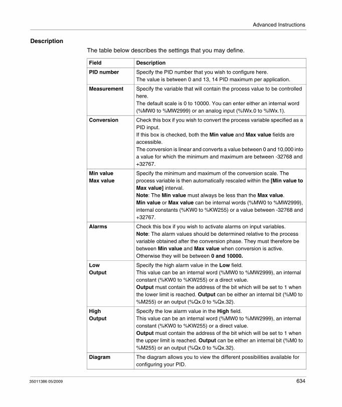
Advanced Instructions
Description
The table below describes the settings that you may define.
Field Description
PID number Specify the PID number that you wish to configure here.The value is between 0 and 13, 14 PID maximum per application.
Measurement Specify the variable that will contain the process value to be controlled here.The default scale is 0 to 10000. You can enter either an internal word (%MW0 to %MW2999) or an analog input (%IWx.0 to %IWx.1).
Conversion Check this box if you wish to convert the process variable specified as a PID input.If this box is checked, both the Min value and Max value fields are accessible.The conversion is linear and converts a value between 0 and 10,000 into a value for which the minimum and maximum are between -32768 and +32767.
Min valueMax value
Specify the minimum and maximum of the conversion scale. The process variable is then automatically rescaled within the [Min value to Max value] interval.Note: The Min value must always be less than the Max value.Min value or Max value can be internal words (%MW0 to %MW2999), internal constants (%KW0 to %KW255) or a value between -32768 and +32767.
Alarms Check this box if you wish to activate alarms on input variables.Note: The alarm values should be determined relative to the process variable obtained after the conversion phase. They must therefore be between Min value and Max value when conversion is active. Otherwise they will be between 0 and 10000.
LowOutput
Specify the high alarm value in the Low field.This value can be an internal word (%MW0 to %MW2999), an internal constant (%KW0 to %KW255) or a direct value.Output must contain the address of the bit which will be set to 1 when the lower limit is reached. Output can be either an internal bit (%M0 to %M255) or an output (%Qx.0 to %Qx.32).
HighOutput
Specify the low alarm value in the High field.This value can be an internal word (%MW0 to %MW2999), an internal constant (%KW0 to %KW255) or a direct value.Output must contain the address of the bit which will be set to 1 when the upper limit is reached. Output can be either an internal bit (%M0 to %M255) or an output (%Qx.0 to %Qx.32).
Diagram The diagram allows you to view the different possibilities available for configuring your PID.
35011386 05/2009 634

Advanced Instructions
PID Tab of PID function
At a Glance
The PID tab is used to enter the internal PID parameters.
NOTE: It is accessible in offline mode.
PID Tab of the PID Function
The screen below is used to enter the internal PID parameters.
635 35011386 05/2009
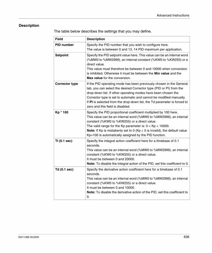
Advanced Instructions
Description
The table below describes the settings that you may define.
Field Description
PID number Specify the PID number that you wish to configure here.The value is between 0 and 13, 14 PID maximum per application.
Setpoint Specify the PID setpoint value here. This value can be an internal word (%MW0 to %MW2999), an internal constant (%KW0 to %KW255) or a direct value.This value must therefore be between 0 and 10000 when conversion is inhibited. Otherwise it must be between the Min value and the Max value for the conversion.
Corrector type If the PID operating mode has been previously chosen in the General tab, you can select the desired Corrector type (PID or PI) from the drop-down list. If other operating modes have been chosen the Corrector type is set to automatic and cannot be modified manually.If PI is selected from the drop-down list, the Td parameter is forced to zero and this field is disabled.
Kp * 100 Specify the PID proportional coefficient multiplied by 100 here.This value can be an internal word (%MW0 to %MW2999), an internal constant (%KW0 to %KW255) or a direct value.The valid range for the Kp parameter is: 0 < Kp < 10000.Note: If Kp is mistakenly set to 0 (Kp ≤ 0 is invalid), the default value Kp=100 is automatically assigned by the PID function.
TI (0.1 sec) Specify the integral action coefficient here for a timebase of 0.1 seconds.This value can be an internal word (%MW0 to %MW2999), an internal constant (%KW0 to %KW255) or a direct value.It must be between 0 and 20000. Note: To disable the integral action of the PID, set this coefficient to 0.
Td (0.1 sec) Specify the derivative action coefficient here for a timebase of 0.1 seconds.This value can be an internal word (%MW0 to %MW2999), an internal constant (%KW0 to %KW255) or a direct value.It must be between 0 and 10000.Note: To disable the derivative action of the PID, set this coefficient to 0.
35011386 05/2009 636
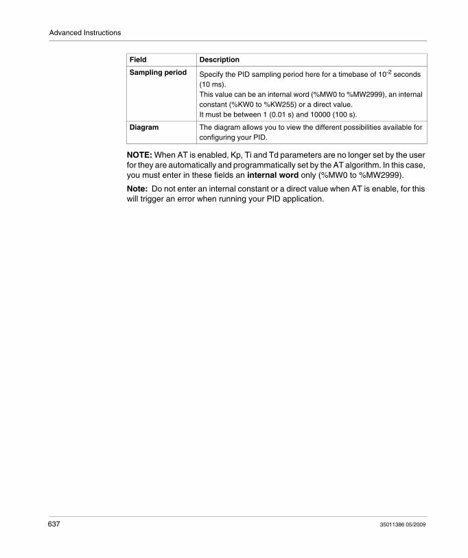
Advanced Instructions
NOTE: When AT is enabled, Kp, Ti and Td parameters are no longer set by the user for they are automatically and programmatically set by the AT algorithm. In this case, you must enter in these fields an internal word only (%MW0 to %MW2999).
Note: Do not enter an internal constant or a direct value when AT is enable, for this will trigger an error when running your PID application.
Sampling period Specify the PID sampling period here for a timebase of 10-2 seconds (10 ms).This value can be an internal word (%MW0 to %MW2999), an internal constant (%KW0 to %KW255) or a direct value.It must be between 1 (0.01 s) and 10000 (100 s).
Diagram The diagram allows you to view the different possibilities available for configuring your PID.
Field Description
637 35011386 05/2009
Advanced Instructions
AT Tab of PID Function
At a Glance
The setting of correct PID parameters may be complex and time-consuming. This can make process control difficult to setup for the less experienced, though not necessarily for a process control professional. Thus, optimum tuning may sometimes be difficult to achieve.
The PID Auto-Tuning algorithm is designed to automatically determine adequate values for the following four PID terms:
Gain factor,Integral value,Derivative value, andDirect or Reverse action.
Thus, the AT function can provide rapid and fine tuning for the process loop.
AT Requirements
PID Auto-tuning is particularly suited for temperature control processes.
In general, the processes that can be controlled by the AT function must meet the following requirements:
the process is mostly linear over the entire operating range,the process response to a level change of the analog output follows a transient asymptotic pattern, andthere is little disturbance in process variables. (In the case of a temperature control process, this implies there is no abnormally high rate of heat exchange between the process and its environment.)
35011386 05/2009 638
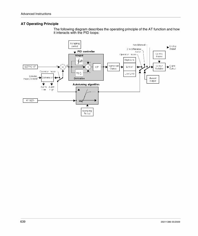
Advanced Instructions
AT Operating Principle
The following diagram describes the operating principle of the AT function and how it interacts with the PID loops:
639 35011386 05/2009
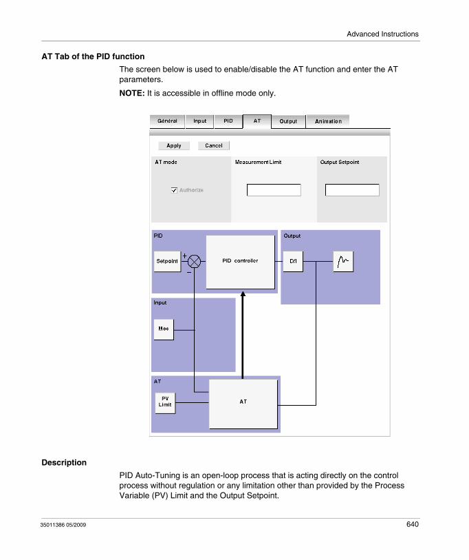
Advanced Instructions
AT Tab of the PID function
The screen below is used to enable/disable the AT function and enter the AT parameters.
NOTE: It is accessible in offline mode only.
Description
PID Auto-Tuning is an open-loop process that is acting directly on the control process without regulation or any limitation other than provided by the Process Variable (PV) Limit and the Output Setpoint.
35011386 05/2009 640
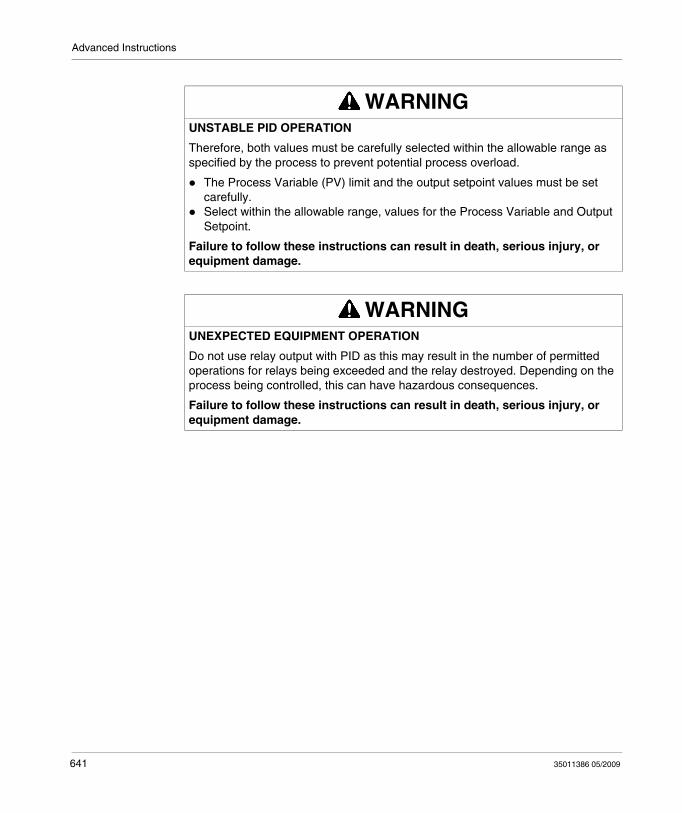
Advanced Instructions
WARNINGUNSTABLE PID OPERATION
Therefore, both values must be carefully selected within the allowable range as specified by the process to prevent potential process overload.
The Process Variable (PV) limit and the output setpoint values must be set carefully.Select within the allowable range, values for the Process Variable and Output Setpoint.
Failure to follow these instructions can result in death, serious injury, or equipment damage.
WARNINGUNEXPECTED EQUIPMENT OPERATION
Do not use relay output with PID as this may result in the number of permitted operations for relays being exceeded and the relay destroyed. Depending on the process being controlled, this can have hazardous consequences.
Failure to follow these instructions can result in death, serious injury, or equipment damage.
641 35011386 05/2009
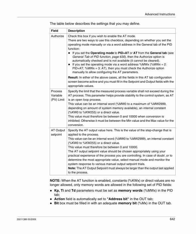
Advanced Instructions
The table below describes the settings that you may define.
NOTE: When the AT function is enabled, constants (%KWx) or direct values are no longer allowed, only memory words are allowed in the following set of PID fields:
Kp, Ti and Td parameters must be set as memory words (%MWx) in the PID tab;Action field is automatically set to "Address bit" in the OUT tab;Bit box must be filled in with an adequate memory bit (%Mx) in the OUT tab.
Field Description
Authorize Check this box if you wish to enable the AT mode.There are two ways to use this checkbox, depending on whether you set the operating mode manually or via a word address in the General tab of the PID function:
If you set the Operating mode to PID+AT or AT from the General tab (see General Tab of PID function, page 630), then the Authorize option is automatically checked and is not available (it cannot be cleared).If you set the operating mode via a word address %MWx (%MWx = 2: PID+AT; %MWx = 3: AT), then you must check the Authorize option manually to allow configuring the AT parameters.
Result: In either of the above cases, all the fields in this AT tab configuration screen become active and you must fill in the Setpoint and Output fields with the appropriate values.
Process Variable (PV) Limit
Specify the limit that the measured process variable shall not exceed during the AT process. This parameter helps provide stability to the control system, as AT is an open loop process.This value can be an internal word (%MW0 to a maximum of %MW2999, depending on amount of system memory available), an internal constant (%KW0 to %KW255) or a direct value.This value must therefore be between 0 and 10000 when conversion is inhibited. Otherwise it must be between the Min value and the Max value for the conversion.
AT Output setpoint
Specify the AT output value here. This is the value of the step-change that is applied to the process.This value can be an internal word (%MW0 to %MW2999), an internal constant (%KW0 to %KW255) or a direct value.This value must therefore be between 0 and 10000.The AT output setpoint value should be chosen appropriately using your practical experience of the process you are controlling. In case of doubt ,or to determine the most appropriate value, select manual mode and monitor the system response to various manual output setpoint trials.Note: The AT Output Setpoint must always be larger than the output last applied to the process.
35011386 05/2009 642

Advanced Instructions
Calculated Kp, Ti, Td Coefficients
Once the AT process is complete, the calculated Kp, Ti and Td PID coefficients:are stored in their respective memory words (%MWx), andcan be viewed in the Animation tab, in TwidoSuite online mode only.
643 35011386 05/2009
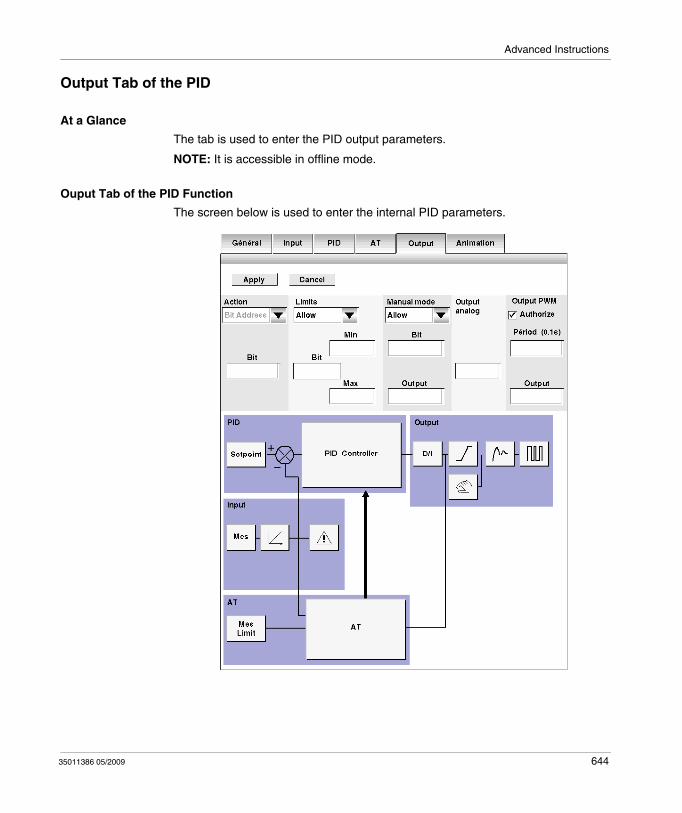
Advanced Instructions
Output Tab of the PID
At a Glance
The tab is used to enter the PID output parameters.
NOTE: It is accessible in offline mode.
Ouput Tab of the PID Function
The screen below is used to enter the internal PID parameters.
35011386 05/2009 644
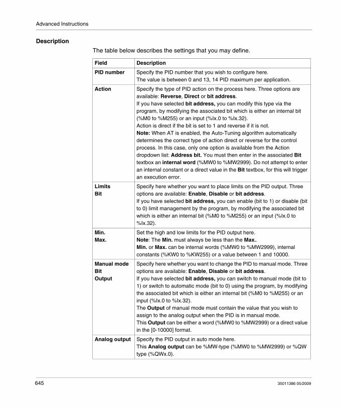
Advanced Instructions
Description
The table below describes the settings that you may define.
Field Description
PID number Specify the PID number that you wish to configure here.The value is between 0 and 13, 14 PID maximum per application.
Action Specify the type of PID action on the process here. Three options are available: Reverse, Direct or bit address.If you have selected bit address, you can modify this type via the program, by modifying the associated bit which is either an internal bit (%M0 to %M255) or an input (%Ix.0 to %Ix.32).Action is direct if the bit is set to 1 and reverse if it is not.Note: When AT is enabled, the Auto-Tuning algorithm automatically determines the correct type of action direct or reverse for the control process. In this case, only one option is available from the Action dropdown list: Address bit. You must then enter in the associated Bit textbox an internal word (%MW0 to %MW2999). Do not attempt to enter an internal constant or a direct value in the Bit textbox, for this will trigger an execution error.
LimitsBit
Specify here whether you want to place limits on the PID output. Three options are available: Enable, Disable or bit address.If you have selected bit address, you can enable (bit to 1) or disable (bit to 0) limit management by the program, by modifying the associated bit which is either an internal bit (%M0 to %M255) or an input (%Ix.0 to %Ix.32).
Min.Max.
Set the high and low limits for the PID output here.Note: The Min. must always be less than the Max..Min. or Max. can be internal words (%MW0 to %MW2999), internal constants (%KW0 to %KW255) or a value between 1 and 10000.
Manual modeBitOutput
Specify here whether you want to change the PID to manual mode. Three options are available: Enable, Disable or bit address.If you have selected bit address, you can switch to manual mode (bit to 1) or switch to automatic mode (bit to 0) using the program, by modifying the associated bit which is either an internal bit (%M0 to %M255) or an input (%Ix.0 to %Ix.32).The Output of manual mode must contain the value that you wish to assign to the analog output when the PID is in manual mode.This Output can be either a word (%MW0 to %MW2999) or a direct value in the [0-10000] format.
Analog output Specify the PID output in auto mode here.This Analog output can be %MW-type (%MW0 to %MW2999) or %QW type (%QWx.0).
645 35011386 05/2009
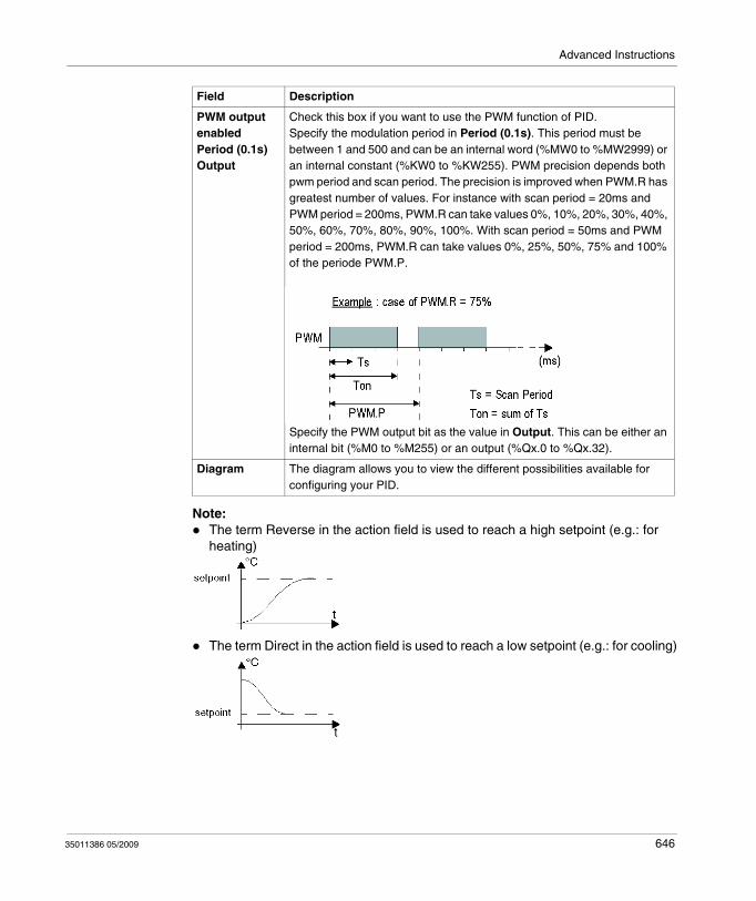
Advanced Instructions
Note:The term Reverse in the action field is used to reach a high setpoint (e.g.: for heating)
The term Direct in the action field is used to reach a low setpoint (e.g.: for cooling)
PWM output enabledPeriod (0.1s)Output
Check this box if you want to use the PWM function of PID.Specify the modulation period in Period (0.1s). This period must be between 1 and 500 and can be an internal word (%MW0 to %MW2999) or an internal constant (%KW0 to %KW255). PWM precision depends both pwm period and scan period. The precision is improved when PWM.R has greatest number of values. For instance with scan period = 20ms and PWM period = 200ms, PWM.R can take values 0%, 10%, 20%, 30%, 40%, 50%, 60%, 70%, 80%, 90%, 100%. With scan period = 50ms and PWM period = 200ms, PWM.R can take values 0%, 25%, 50%, 75% and 100% of the periode PWM.P.
Specify the PWM output bit as the value in Output. This can be either an internal bit (%M0 to %M255) or an output (%Qx.0 to %Qx.32).
Diagram The diagram allows you to view the different possibilities available for configuring your PID.
Field Description
35011386 05/2009 646

Advanced Instructions
How to Access PID Debugging
At a Glance
The following paragraphs describe how to access the PID debugging screens on TWIDO controllers.
Procedure
The following table describes the procedure for accessing the PID debugging screens:
Step Action
1 Check that you are in online mode.
2 In the monitor software configuration screen, select Advanced Objects from the Object Category frame and choose PID from the Objects Type frame.
3 Select the desired PID# from the PID table.Note: You can also double-click the PID graphic element in the ladder rung to access the PID configuratrion window.
4 Click the Animation tab.Result: The PID configuration window opens and displays the Animation (see page 648) tab by default.
647 35011386 05/2009

Advanced Instructions
Animation Tab of PID Function
At a Glance
The tab is used to debug the PID.
The diagram depends on the type of PID control that you have created. Only configured elements are shown.
The display is dynamic. Active links are shown in red and inactive links are shown in black.
NOTE: It is accessible in online mode. In this mode, when the PLC is in periodic task, the value displayed in the Ts Field (in the PID software configuration screen) can be different with the parameter entered (%MW). The Ts value is a multiple of the periodic task, whereas the %MW value is the value read by the PLC.
35011386 05/2009 648
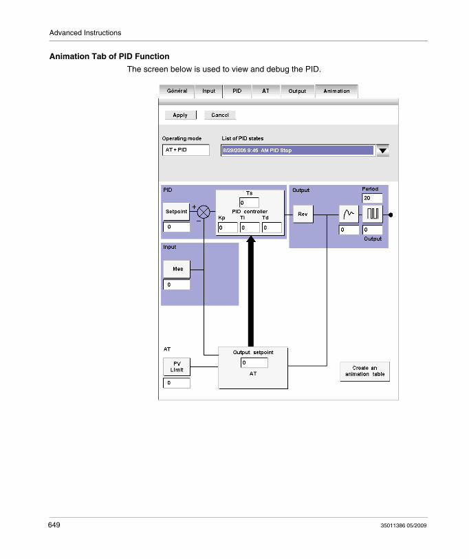
Advanced Instructions
Animation Tab of PID Function
The screen below is used to view and debug the PID.
649 35011386 05/2009
Advanced Instructions
Description
The following table describes the different zones of the window.
Field Description
PID number Specify the PID number that you wish to debug here.The value is between 0 and 13, 14 PID maximum per application.
Operating mode This field shows the current PID operating mode.
List of PID states This dropdown list allows you to view the last 15 PID states in real time. This list is updated with each change of state indicating the date and time of the change as well as the current state.
Create an Animation Table
Click on Create an Animation Table, to create a file containing all the variables shown in the diagram to enable you modify them online and debug your PID.
35011386 05/2009 650
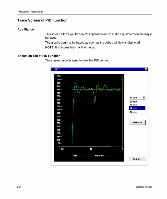
Advanced Instructions
Trace Screen of PID Function
At a Glance
This screen allows you to view PID operation and to make adjustments to the way it behaves.
The graphs begin to be traced as soon as the debug window is displayed.
NOTE: It is accessible in online mode.
Animation Tab of PID Function
The screen below is used to view the PID control.
651 35011386 05/2009
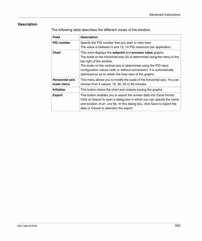
Advanced Instructions
Description
The following table describes the different zones of the window.
Field Description
PID number Specify the PID number that you wish to view here.The value is between 0 and 13, 14 PID maximum per application.
Chart This zone displays the setpoint and process value graphs.The scale on the horizontal axis (X) is determined using the menu to the top right of the window.The scale on the vertical axis is determined using the PID input configuration values (with or without conversion). It is automatically optimized so as to obtain the best view of the graphs.
Horizontal axis scale menu
This menu allows you to modify the scale of the horizontal axis. You can choose from 4 values: 15, 30, 45 or 60 minutes.
Initialize This button clears the chart and restarts tracing the graphs.
Export This button enables you to export the screen data into Excel format. Click on Export to open a dialog box in which you can specify the name and location of an .cvs file. In this dialog box, click Save to export the data or Cancel to abandon the export.
35011386 05/2009 652
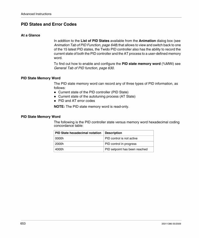
Advanced Instructions
PID States and Error Codes
At a Glance
In addition to the List of PID States available from the Animation dialog box (see Animation Tab of PID Function, page 648) that allows to view and switch back to one of the 15 latest PID states, the Twido PID controller also has the ability to record the current state of both the PID controller and the AT process to a user-defined memory word.
To find out how to enable and configure the PID state memory word (%MWi) see General Tab of PID function, page 630.
PID State Memory Word
The PID state memory word can record any of three types of PID information, as follows:
Current state of the PID controller (PID State)Current state of the autotuning process (AT State)PID and AT error codes
NOTE: The PID state memory word is read-only.
PID State Memory Word
The following is the PID controller state versus memory word hexadecimal coding concordance table:
PID State hexadecimal notation Description
0000h PID control is not active
2000h PID control in progress
4000h PID setpoint has been reached
653 35011386 05/2009
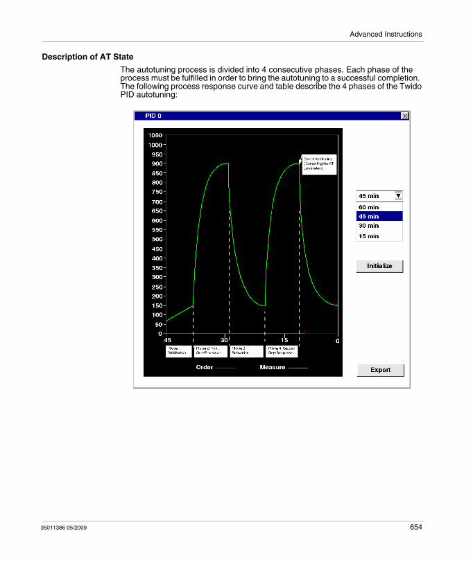
Advanced Instructions
Description of AT State
The autotuning process is divided into 4 consecutive phases. Each phase of the process must be fulfilled in order to bring the autotuning to a successful completion. The following process response curve and table describe the 4 phases of the Twido PID autotuning:
35011386 05/2009 654
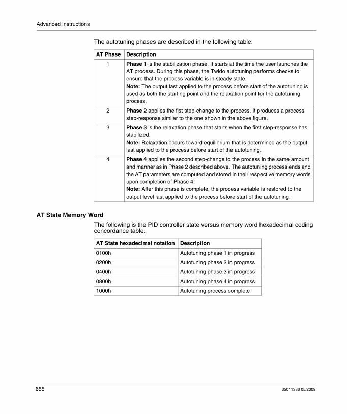
Advanced Instructions
The autotuning phases are described in the following table:
AT State Memory Word
The following is the PID controller state versus memory word hexadecimal coding concordance table:
AT Phase Description
1 Phase 1 is the stabilization phase. It starts at the time the user launches the AT process. During this phase, the Twido autotuning performs checks to ensure that the process variable is in steady state.Note: The output last applied to the process before start of the autotuning is used as both the starting point and the relaxation point for the autotuning process.
2 Phase 2 applies the fist step-change to the process. It produces a process step-response similar to the one shown in the above figure.
3 Phase 3 is the relaxation phase that starts when the first step-response has stabilized.Note: Relaxation occurs toward equilibrium that is determined as the output last applied to the process before start of the autotuning.
4 Phase 4 applies the second step-change to the process in the same amount and manner as in Phase 2 described above. The autotuning process ends and the AT parameters are computed and stored in their respective memory words upon completion of Phase 4.Note: After this phase is complete, the process variable is restored to the output level last applied to the process before start of the autotuning.
AT State hexadecimal notation Description
0100h Autotuning phase 1 in progress
0200h Autotuning phase 2 in progress
0400h Autotuning phase 3 in progress
0800h Autotuning phase 4 in progress
1000h Autotuning process complete
655 35011386 05/2009
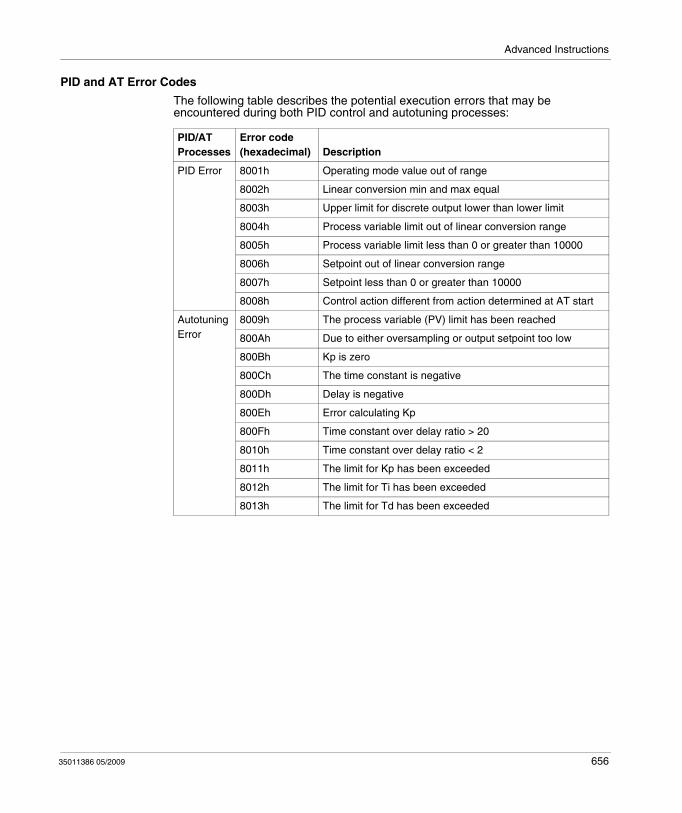
Advanced Instructions
PID and AT Error Codes
The following table describes the potential execution errors that may be encountered during both PID control and autotuning processes:
PID/AT Processes
Error code (hexadecimal) Description
PID Error 8001h Operating mode value out of range
8002h Linear conversion min and max equal
8003h Upper limit for discrete output lower than lower limit
8004h Process variable limit out of linear conversion range
8005h Process variable limit less than 0 or greater than 10000
8006h Setpoint out of linear conversion range
8007h Setpoint less than 0 or greater than 10000
8008h Control action different from action determined at AT start
Autotuning Error
8009h The process variable (PV) limit has been reached
800Ah Due to either oversampling or output setpoint too low
800Bh Kp is zero
800Ch The time constant is negative
800Dh Delay is negative
800Eh Error calculating Kp
800Fh Time constant over delay ratio > 20
8010h Time constant over delay ratio < 2
8011h The limit for Kp has been exceeded
8012h The limit for Ti has been exceeded
8013h The limit for Td has been exceeded
35011386 05/2009 656
Advanced Instructions
PID Tuning with Auto-Tuning (AT)
Overview of PID Tuning
The PID control function relies on the following three user-defined parameters: Kp, Ti and Td. PID tuning aims at determining these process parameters accurately to provide refined control of the process.
Scope of the Auto-Tuning
The AT function of the Twido PLC is especially suited for automatic tuning of thermal processes. As values of the PID parameters may vary greatly from one control process to another, the auto-tuning function provided by the Twido PLC can help you determine more accurate values than simply provided by best guesses, with less effort.
NOTE: Not recommended to use the auto-tuning when other PID are running.
Auto-Tuning Requirements
When using the auto-tuning function, make sure the control process and the Twido PLC meet all of the following four requirements:
The control process must be an open-loop, stable system.At the start of the auto-tuning run, the control process must be in steady state with a null process input (e.g.: an oven or a furnace shall be at ambient temperature.)During operation of the auto-tuning, make sure that no disturbances enter through the process for either computed parameters will be incorrect or the auto-tuning process will not operate correctly (e.g.: the door of the oven shall not be opened, not even momentarily.)Configure the Twido PLC to scan in Periodic mode. Once you have determined the correct sampling period (Ts) for the auto-tuning, the scan period must be configured so that the sampling period (Ts) is an exact multiple of the Twido PLC scan period.
NOTE: To ensure a correct run of the PID control and of the auto-tuning process, it is essential that the Twido PLC be configured to execute scans in Periodic mode (not Cyclic). In Periodic mode, each scan of the PLC starts at regular time intervals. This way, the sampling rate is constant throughout the measurement duration (unlike cyclic mode where a scan starts as soon as the previous one ends, which makes the sampling period unbalanced from scan to scan.)
657 35011386 05/2009
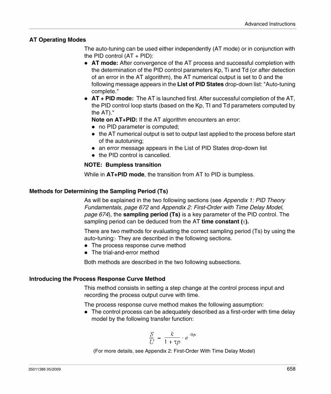
Advanced Instructions
AT Operating Modes
The auto-tuning can be used either independently (AT mode) or in conjunction with the PID control (AT + PID):
AT mode: After convergence of the AT process and successful completion with the determination of the PID control parameters Kp, Ti and Td (or after detection of an error in the AT algorithm), the AT numerical output is set to 0 and the following message appears in the List of PID States drop-down list: "Auto-tuning complete."AT + PID mode: The AT is launched first. After successful completion of the AT, the PID control loop starts (based on the Kp, TI and Td parameters computed by the AT)."Note on AT+PID: If the AT algorithm encounters an error:
no PID parameter is computed;the AT numerical output is set to output last applied to the process before start of the autotuning;an error message appears in the List of PID States drop-down listthe PID control is cancelled.
NOTE: Bumpless transition
While in AT+PID mode, the transition from AT to PID is bumpless.
Methods for Determining the Sampling Period (Ts)
As will be explained in the two following sections (see Appendix 1: PID Theory Fundamentals, page 672 and Appendix 2: First-Order with Time Delay Model, page 674), the sampling period (Ts) is a key parameter of the PID control. The sampling period can be deduced from the AT time constant (τ).
There are two methods for evaluating the correct sampling period (Ts) by using the auto-tuning:· They are described in the following sections.
The process response curve methodThe trial-and-error method
Both methods are described in the two following subsections.
Introducing the Process Response Curve Method
This method consists in setting a step change at the control process input and recording the process output curve with time.
The process response curve method makes the following assumption:The control process can be adequately described as a first-order with time delay model by the following transfer function:
(For more details, see Appendix 2: First-Order With Time Delay Model)
35011386 05/2009 658
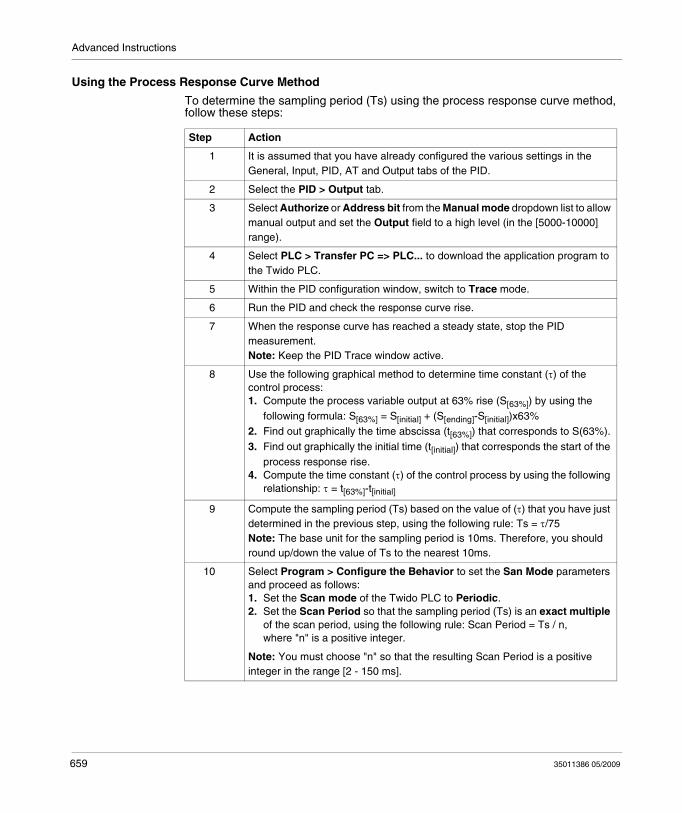
Advanced Instructions
Using the Process Response Curve Method
To determine the sampling period (Ts) using the process response curve method, follow these steps:
Step Action
1 It is assumed that you have already configured the various settings in the General, Input, PID, AT and Output tabs of the PID.
2 Select the PID > Output tab.
3 Select Authorize or Address bit from the Manual mode dropdown list to allow manual output and set the Output field to a high level (in the [5000-10000] range).
4 Select PLC > Transfer PC => PLC... to download the application program to the Twido PLC.
5 Within the PID configuration window, switch to Trace mode.
6 Run the PID and check the response curve rise.
7 When the response curve has reached a steady state, stop the PID measurement.Note: Keep the PID Trace window active.
8 Use the following graphical method to determine time constant (τ) of the control process:1. Compute the process variable output at 63% rise (S[63%]) by using the
following formula: S[63%] = S[initial] + (S[ending]-S[initial])x63%2. Find out graphically the time abscissa (t[63%]) that corresponds to S(63%).3. Find out graphically the initial time (t[initial]) that corresponds the start of the
process response rise.4. Compute the time constant (τ) of the control process by using the following
relationship: τ = t[63%]-t[initial]
9 Compute the sampling period (Ts) based on the value of (τ) that you have just determined in the previous step, using the following rule: Ts = τ/75Note: The base unit for the sampling period is 10ms. Therefore, you should round up/down the value of Ts to the nearest 10ms.
10 Select Program > Configure the Behavior to set the San Mode parameters and proceed as follows:1. Set the Scan mode of the Twido PLC to Periodic.2. Set the Scan Period so that the sampling period (Ts) is an exact multiple
of the scan period, using the following rule: Scan Period = Ts / n,where "n" is a positive integer.
Note: You must choose "n" so that the resulting Scan Period is a positive integer in the range [2 - 150 ms].
659 35011386 05/2009
Advanced Instructions
Example of Process Response Curve
This example shows you how to measure the time constant (τ) of a simple thermal process by using the process response curve method described in the previous subsection.
The experimental setup for the time constant measurement is as follows:The control process consists in a forced air oven equipped with a heating lamp.Temperature measurements are gathered by the Twido PLC via a Pt100 probe, and temperature data are recorded in °C.The Twido PLC drives a heating lamp via the PWM discrete output of the PID.
The experiment is carried out as follows:
Step Action
1 The PID Output tab is selected from the PID configuration screen.
2 Manual mode is selected from the Output tab.
3 The manual mode Output is set to 10000.
4 The PID run is launched from the PID Trace tab.
5 The PID run is stopped when the oven's temperature has reached a steady state.
35011386 05/2009 660
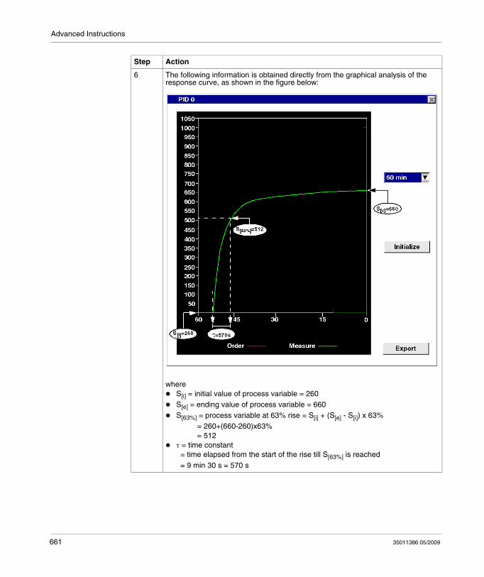
Advanced Instructions
6 The following information is obtained directly from the graphical analysis of the response curve, as shown in the figure below:
whereS[i] = initial value of process variable = 260S[e] = ending value of process variable = 660S[63%] = process variable at 63% rise = S[i] + (S[e] - S[i]) x 63% = 260+(660-260)x63% = 512τ = time constant = time elapsed from the start of the rise till S[63%] is reached = 9 min 30 s = 570 s
Step Action
661 35011386 05/2009
Advanced Instructions
Trial-and-Error Method
The trial-and-error method consists in providing successive guesses of the sampling period to the auto-tuning function until the auto-tuning algorithm converges successfully towards Kp, Ti and Td that are deemed satisfactory by the user.
NOTE: Unlike the process response curve method, the trial-and-error method is not based on any approximation law of the process response. However, it has the advantage of converging towards a value of the sampling period that is in the same order of magnitude as the actual value.
Top perform a trial-and-error estimation of the auto-tuning parameters, follow these steps:
7 The sampling period (Ts) is determined using the following relationship:Ts = τ/75 = 570/75 = 7.6 s (7600 ms)
8 In the Program > Scan mode edit dialog box, the Scan Period must be set so that the sampling period (Ts) is an exact multiple of the scan period, as in the following example: Scan Period = Ts/76 = 7600/76 = 100 ms (which satisfies the condition: 2 ms ≤ Scan Period ≤ 150 ms.)
Step Action
Step Action
1 Select the AT tab from the PID configuration window.
2 Set the Output limitation of AT to 10000.
3 Select the PID tab from the PID configuration window.
4 Provide the first or nth guess in the Sampling Period field.Note: If you do not have any first indication of the possible range for the sampling period, set this value to the minimum possible: 1 (1 unit of 10 ms).
5 Select PLC > Transfer PC => PLC... from menu bar to download the application program to the Twido PLC.
6 Launch Auto-Tuning.
7 Select the Animation tab from the PID configuration screen.
8 Wait till the auto-tuning process ends.
35011386 05/2009 662
Advanced Instructions
Adjusting PID Parameters
To refine the process regulation provided by the PID parameters (Kp, Ti, Td) obtained from auto-tuning, you also have the ability to adjust those parameter values manually, directly from the PID tab of the PID configuration screen or via the corresponding memory words (%MW).
Limitations on Using the Auto-tuning and the PID Control
Auto-tuning is best suited for processes whose time constant (τ) and delay-time (θ) meet the following requirement: 10 s < (τ + θ) < 2700 s (i.e.: 45 min)
NOTE: Auto-tuning will not work when: (τ/θ) < 2 or (τ/θ) > 20.
PID control is best suited for the regulation of processes that satisfy the following condition: 2 < (τ/θ) < 20 where (τ) is the time constant of the process and (θ) is the delay-time.
NOTE: Depending on the ratio (τ/θ):
(τ/θ) < 2 : The PID regulation has reached its limitations; more advanced regulation techniques are needed in this case.(τ/θ) > 20 : In this case, a simple on/off (or two-step) controller can be used in place of the PID controller.
9 Two cases may occur:Auto-tuning completes successfully: You may continue to Step 9.Auto-tuning unsuccessfull: This means the current guess for the sampling period (Ts) is not correct. Try a new Ts guess and repeat steps 3 through 8, as many times as required until the auto-tuning process eventually converges.Follow these guidelines to provide a new Ts guess:
AT ends with the error message "The computed time constant is negative!": This means the sampling period Ts is too large. You should decrease the value of Ts to provide as new guess.AT ends with the error message "Sampling error!": This means the sampling period Ts is too small. You should increase the value of Ts to provide as new guess.
10 You may now view the PID control parameters (Kp, Ti and Td) in Animation tab, and adjust them in the PID tab of the PID configuration screen, as needed.Note: If the PID regulation provided by this set of control parameters does not provide results that are totally satisfactory, you may still refine the trial-and-error evaluation of the sampling period until you obtain the right set of Kp, Ti and Td control parameters.
Step Action
663 35011386 05/2009
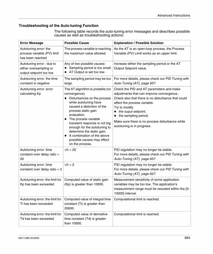
Advanced Instructions
Troubleshooting of the Auto-tuning Function
The following table records the auto-tuning error messages and describes possible causes as well as troubleshooting actions:
Error Message Possible Cause Explanation / Possible Solution
Autotuning error: the process variable (PV) limit has been reached
The process variable is reaching the maximum value allowed.
As the AT is an open-loop process, the Process Variable (PV) Limit works as an upper limit.
Autotuning error : due to either oversampling or output setpoint too low
Any of two possible causes:Sampling period is too small.AT Output is set too low.
Increase either the sampling period or the AT Output Setpoint value.
Autotuning error: the time constant is negative
The sampling period may be too large.
For more details, please check out PID Tuning with Auto-Tuning (AT), page 657.
Autotuning error: error calculating Kp
The AT algorithm is unstable (no convergence).
Disturbances on the process while autotuning have caused a distortion of the process static gain evaluation.The process variable transient response is not big enough for the autotuning to determine the static gain.A combination of the above possible causes may effect on the process.
Check the PID and AT parameters and make adjustments that can improve convergence.Check also that there is no disturbance that could affect the process variable.Try to modify
the ouput setpoint,the sampling period.
Make sure there is no process disturbance while autotuning is in progress.
Autotuning error: time constant over delay ratio > 20
τ/θ > 20 PID regulation may no longer be stable.For more details, please check out PID Tuning with Auto-Tuning (AT), page 657.
Autotuning error: time constant over delay ratio < 2
τ/θ < 2 PID regulation may no longer be stable.For more details, please check out PID Tuning with Auto-Tuning (AT), page 657.
Autotuning error: the limit for Kp has been exceeded
Computed value of static gain (Kp) is greater than 10000.
Measurement sensitivity of some application variables may be too low. The application's measurement range must be rescaled within the [0-10000] interval.
Autotuning error: the limit for Ti has been exceeded
Computed value of integral time constant (Ti) is greater than 20000.
Computational limit is reached.
Autotuning error: the limit for Td has been exceeded
Computed value of derivative time constant (Td) is greater than 10000.
Computational limit is reached.
35011386 05/2009 664
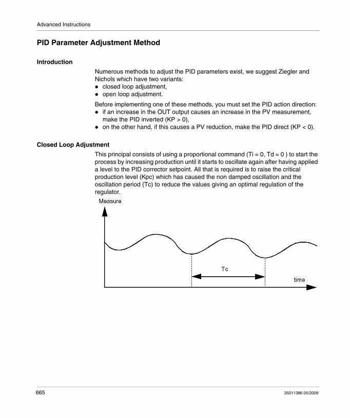
Advanced Instructions
PID Parameter Adjustment Method
Introduction
Numerous methods to adjust the PID parameters exist, we suggest Ziegler and Nichols which have two variants:
closed loop adjustment,open loop adjustment.
Before implementing one of these methods, you must set the PID action direction:if an increase in the OUT output causes an increase in the PV measurement, make the PID inverted (KP > 0),on the other hand, if this causes a PV reduction, make the PID direct (KP < 0).
Closed Loop Adjustment
This principal consists of using a proportional command (Ti = 0, Td = 0 ) to start the process by increasing production until it starts to oscillate again after having applied a level to the PID corrector setpoint. All that is required is to raise the critical production level (Kpc) which has caused the non damped oscillation and the oscillation period (Tc) to reduce the values giving an optimal regulation of the regulator.
665 35011386 05/2009
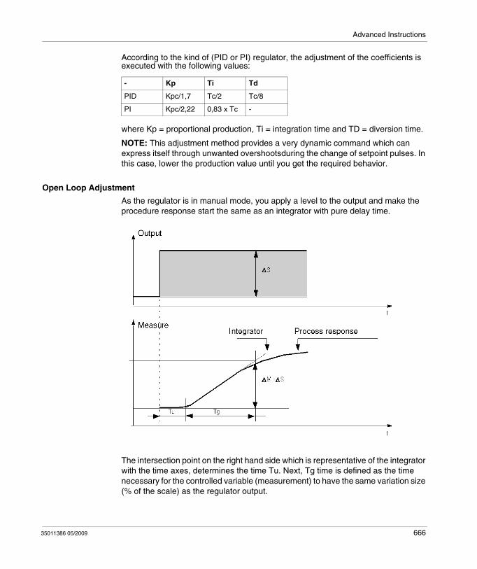
Advanced Instructions
According to the kind of (PID or PI) regulator, the adjustment of the coefficients is executed with the following values:
where Kp = proportional production, Ti = integration time and TD = diversion time.
NOTE: This adjustment method provides a very dynamic command which can express itself through unwanted overshootsduring the change of setpoint pulses. In this case, lower the production value until you get the required behavior.
Open Loop Adjustment
As the regulator is in manual mode, you apply a level to the output and make the procedure response start the same as an integrator with pure delay time.
The intersection point on the right hand side which is representative of the integrator with the time axes, determines the time Tu. Next, Tg time is defined as the time necessary for the controlled variable (measurement) to have the same variation size (% of the scale) as the regulator output.
- Kp Ti Td
PID Kpc/1,7 Tc/2 Tc/8
PI Kpc/2,22 0,83 x Tc -
35011386 05/2009 666
Advanced Instructions
According to the kind of (PID or PI) regulator, the adjustment of the coefficients is executed with the following values:
where Kp = proportional production, Ti = integration time and TD = diversion time.
NOTE: Attention to the units. If the adjustment is carried out in PL7, multiply the value obtained for KP by 100.
This adjustment method also provides a very dynamic command, which can express itself through unwanted overshoots during the change of setpoints’ pulses. In this case, lower the production value until you get the required behavior. The method is interesting because it does not require any assumptions about the nature and the order of the procedure. You can apply it just as well to the stable procedures as to real integrating procedures. It is really interesting in the case of slow procedures (glass industry,…) because the user only requires the beginning of the response to regulate the coefficients Kp, Ti and Td.
- Kp Ti Td
PID -1,2 Tg/Tu 2 x Tu 0,5 x Tu
PI -0,9 Tg/Tu 3,3 x Tu -
667 35011386 05/2009
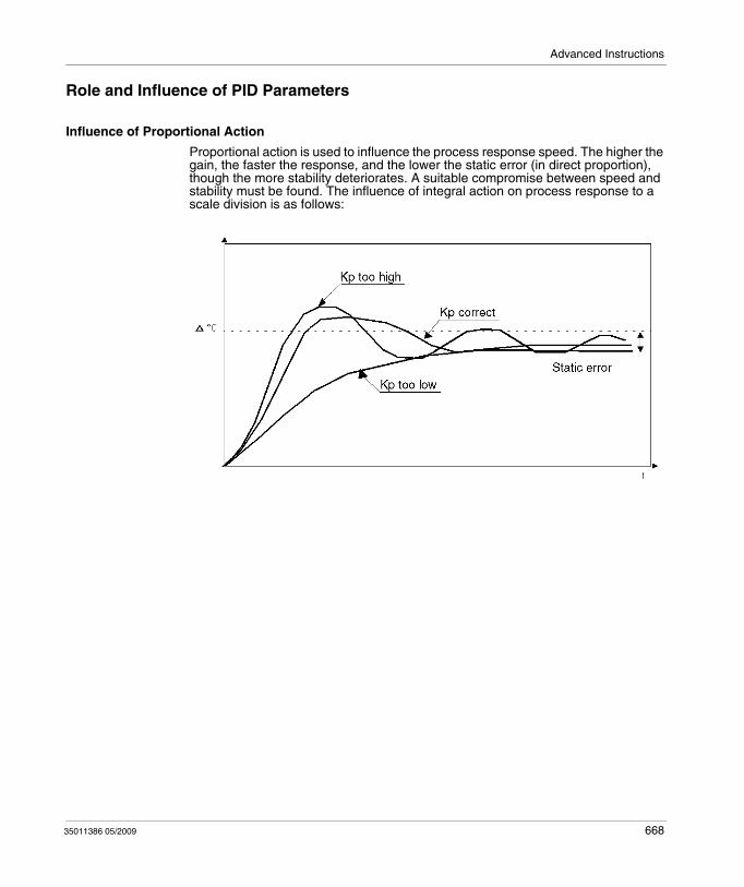
Advanced Instructions
Role and Influence of PID Parameters
Influence of Proportional Action
Proportional action is used to influence the process response speed. The higher the gain, the faster the response, and the lower the static error (in direct proportion), though the more stability deteriorates. A suitable compromise between speed and stability must be found. The influence of integral action on process response to a scale division is as follows:
35011386 05/2009 668
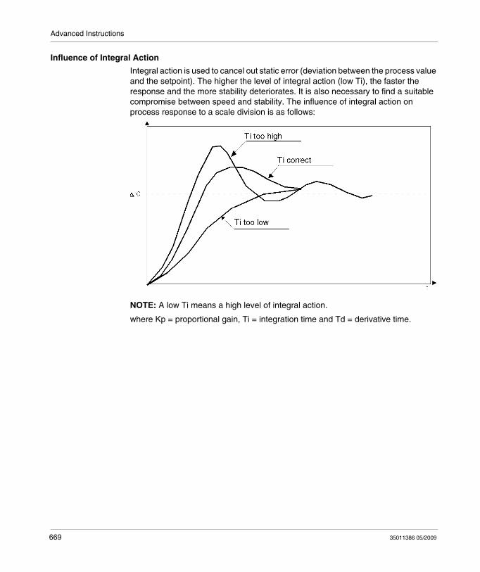
Advanced Instructions
Influence of Integral Action
Integral action is used to cancel out static error (deviation between the process value and the setpoint). The higher the level of integral action (low Ti), the faster the response and the more stability deteriorates. It is also necessary to find a suitable compromise between speed and stability. The influence of integral action on process response to a scale division is as follows:
NOTE: A low Ti means a high level of integral action.
where Kp = proportional gain, Ti = integration time and Td = derivative time.
669 35011386 05/2009
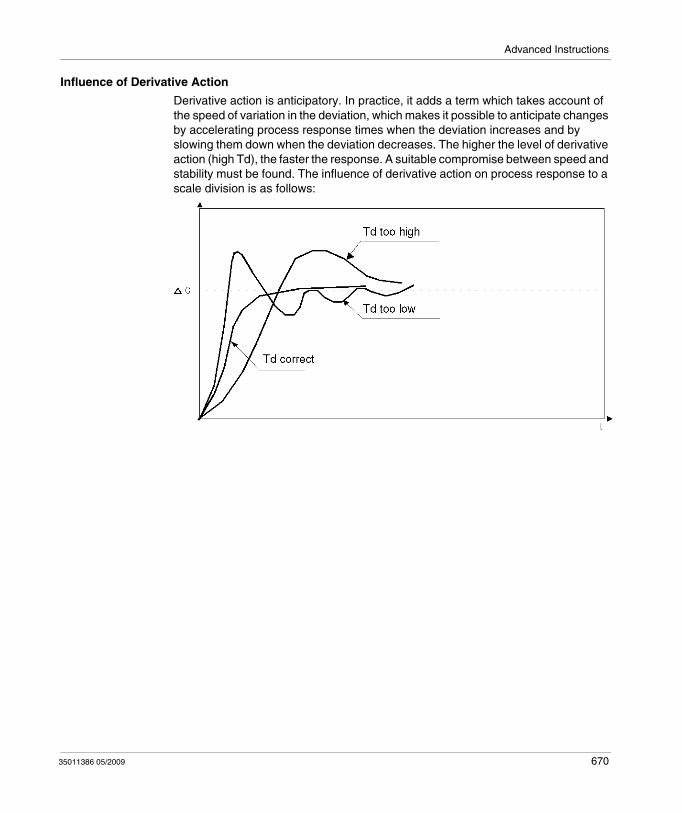
Advanced Instructions
Influence of Derivative Action
Derivative action is anticipatory. In practice, it adds a term which takes account of the speed of variation in the deviation, which makes it possible to anticipate changes by accelerating process response times when the deviation increases and by slowing them down when the deviation decreases. The higher the level of derivative action (high Td), the faster the response. A suitable compromise between speed and stability must be found. The influence of derivative action on process response to a scale division is as follows:
35011386 05/2009 670
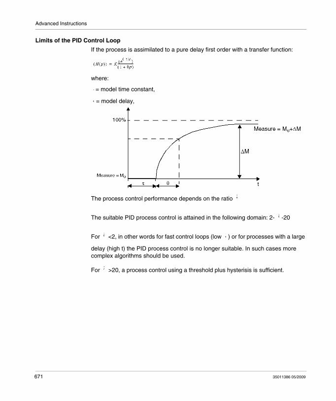
Advanced Instructions
Limits of the PID Control Loop
If the process is assimilated to a pure delay first order with a transfer function:
where:
= model time constant,
= model delay,
The process control performance depends on the ratio
The suitable PID process control is attained in the following domain: 2- -20
For <2, in other words for fast control loops (low ) or for processes with a large
delay (high t) the PID process control is no longer suitable. In such cases more complex algorithms should be used.
For >20, a process control using a threshold plus hysterisis is sufficient.
671 35011386 05/2009
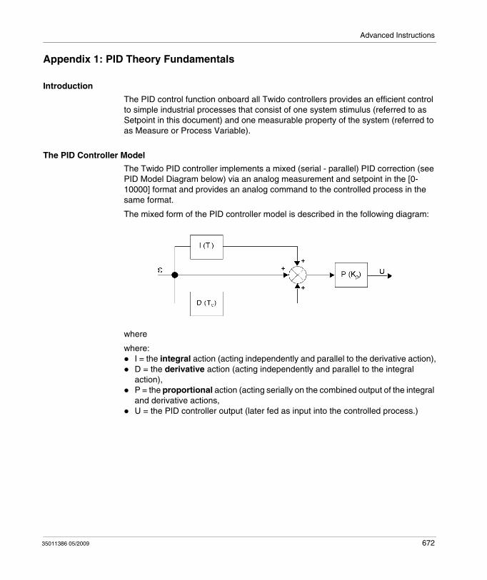
Advanced Instructions
Appendix 1: PID Theory Fundamentals
Introduction
The PID control function onboard all Twido controllers provides an efficient control to simple industrial processes that consist of one system stimulus (referred to as Setpoint in this document) and one measurable property of the system (referred to as Measure or Process Variable).
The PID Controller Model
The Twido PID controller implements a mixed (serial - parallel) PID correction (see PID Model Diagram below) via an analog measurement and setpoint in the [0-10000] format and provides an analog command to the controlled process in the same format.
The mixed form of the PID controller model is described in the following diagram:
where
where:I = the integral action (acting independently and parallel to the derivative action),D = the derivative action (acting independently and parallel to the integral action),P = the proportional action (acting serially on the combined output of the integral and derivative actions,U = the PID controller output (later fed as input into the controlled process.)
35011386 05/2009 672
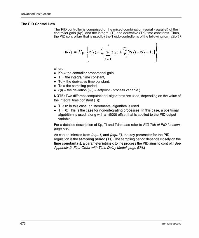
Advanced Instructions
The PID Control Law
The PID controller is comprised of the mixed combination (serial - parallel) of the controller gain (Kp), and the integral (Ti) and derivative (Td) time constants. Thus, the PID control law that is used by the Twido controller is of the following form (Eq.1):
whereKp = the controller proportional gain,Ti = the integral time constant,Td = the derivative time constant,Ts = the sampling period,ε(i) = the deviation (ε(i) = setpoint - process variable.)
NOTE: Two different computational algorithms are used, depending on the value of the integral time constant (Ti):
Ti ≠ 0: In this case, an incremental algortihm is used.Ti = 0: This is the case for non-integrating processes. In this case, a positional algotrithm is used, along with a +5000 offset that is applied to the PID output variable.
For a detailed description of Kp, Ti and Td please refer to PID Tab of PID function, page 635.
As can be inferred from (equ.1) and (equ.1’), the key parameter for the PID regulation is the sampling period (Ts). The sampling period depends closely on the time constant (τ), a parameter intrinsic to the process the PID aims to control. (See Appendix 2: First-Order with Time Delay Model, page 674.)
673 35011386 05/2009
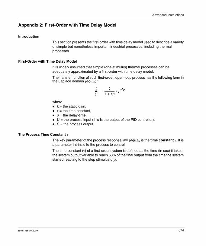
Advanced Instructions
Appendix 2: First-Order with Time Delay Model
Introduction
This section presents the first-order with time delay model used to describe a variety of simple but nonetheless important industrial processes, including thermal processes.
First-Order with Time Delay Model
It is widely assumed that simple (one-stimulus) thermal processes can be adequately approximated by a first-order with time delay model.
The transfer function of such first-order, open-loop process has the following form in the Laplace domain (equ.2):
wherek = the static gain,τ = the time constant,θ = the delay-time,U = the process input (this is the output of the PID controller),S = the process output.
The Process Time Constant τ
The key parameter of the process response law (equ.2) is the time constant τ. It is a parameter intrinsic to the process to control.
The time constant (τ) of a first-order system is defined as the time (in sec) it takes the system output variable to reach 63% of the final output from the time the system started reacting to the step stimulus u(t).
35011386 05/2009 674
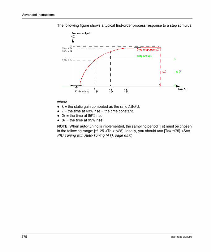
Advanced Instructions
The following figure shows a typical first-order process response to a step stimulus:
wherek = the static gain computed as the ratio ΔS/ΔU,τ = the time at 63% rise = the time constant,2τ = the time at 86% rise,3τ = the time at 95% rise.
NOTE: When auto-tuning is implemented, the sampling period (Ts) must be chosen in the following range: [τ/125 <Ts < τ/25]. Ideally, you should use [Ts= τ/75]. (See PID Tuning with Auto-Tuning (AT), page 657.)
675 35011386 05/2009
Advanced Instructions
18.5 Floating point instructions
Aim of this Section
This section describes advanced floating point (see page 30) instructions in TwidoSuite language.
The Comparison and Assignment instructions are described in the Numerical Processing, page 502
What's in this Section?
This section contains the following topics:
Topic Page
Arithmetic Instructions on Floating Point 677
Trigonometric Instructions 681
Conversion instructions 683
Integer Conversion Instructions <-> Floating 685
35011386 05/2009 676
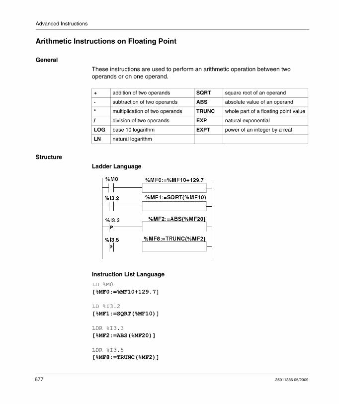
Advanced Instructions
Arithmetic Instructions on Floating Point
General
These instructions are used to perform an arithmetic operation between two operands or on one operand.
Structure
Ladder Language
Instruction List Language
LD %M0[%MF0:=%MF10+129.7]
LD %I3.2[%MF1:=SQRT(%MF10)]
LDR %I3.3[%MF2:=ABS(%MF20)]
LDR %I3.5[%MF8:=TRUNC(%MF2)]
+ addition of two operands SQRT square root of an operand
- subtraction of two operands ABS absolute value of an operand
* multiplication of two operands TRUNC whole part of a floating point value
/ division of two operands EXP natural exponential
LOG base 10 logarithm EXPT power of an integer by a real
LN natural logarithm
677 35011386 05/2009
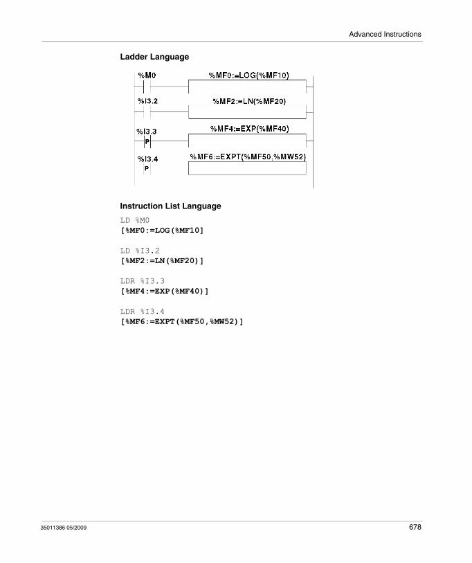
Advanced Instructions
Ladder Language
Instruction List Language
LD %M0[%MF0:=LOG(%MF10]
LD %I3.2[%MF2:=LN(%MF20)]
LDR %I3.3[%MF4:=EXP(%MF40)]
LDR %I3.4[%MF6:=EXPT(%MF50,%MW52)]
35011386 05/2009 678
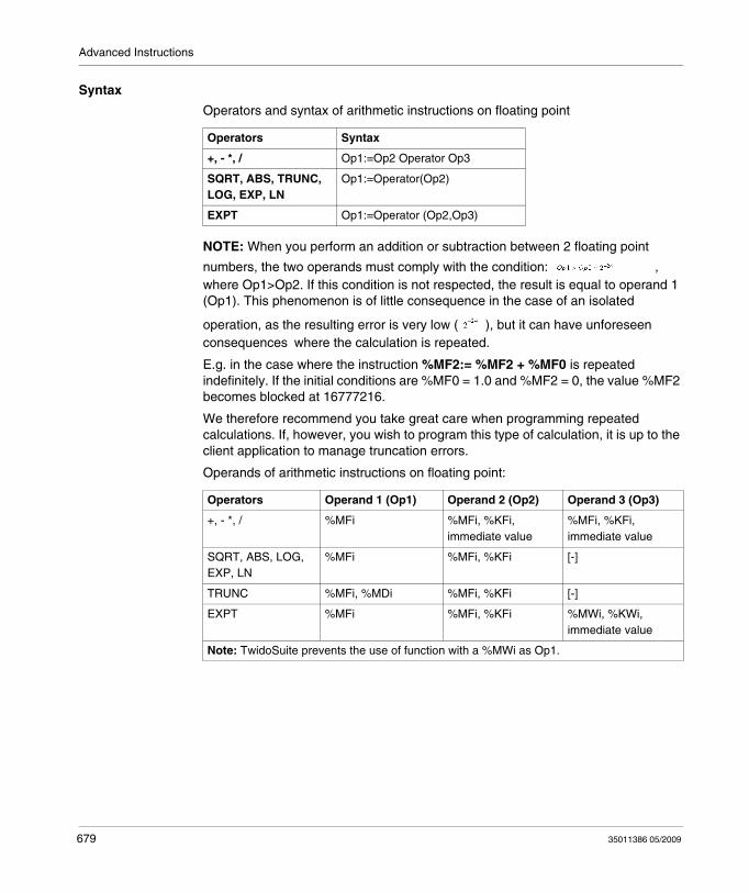
Advanced Instructions
Syntax
Operators and syntax of arithmetic instructions on floating point
NOTE: When you perform an addition or subtraction between 2 floating point
numbers, the two operands must comply with the condition: , where Op1>Op2. If this condition is not respected, the result is equal to operand 1 (Op1). This phenomenon is of little consequence in the case of an isolated
operation, as the resulting error is very low ( ), but it can have unforeseen consequences where the calculation is repeated.
E.g. in the case where the instruction %MF2:= %MF2 + %MF0 is repeated indefinitely. If the initial conditions are %MF0 = 1.0 and %MF2 = 0, the value %MF2 becomes blocked at 16777216.
We therefore recommend you take great care when programming repeated calculations. If, however, you wish to program this type of calculation, it is up to the client application to manage truncation errors.
Operands of arithmetic instructions on floating point:
Operators Syntax
+, - *, / Op1:=Op2 Operator Op3
SQRT, ABS, TRUNC, LOG, EXP, LN
Op1:=Operator(Op2)
EXPT Op1:=Operator (Op2,Op3)
Operators Operand 1 (Op1) Operand 2 (Op2) Operand 3 (Op3)
+, - *, / %MFi %MFi, %KFi, immediate value
%MFi, %KFi, immediate value
SQRT, ABS, LOG, EXP, LN
%MFi %MFi, %KFi [-]
TRUNC %MFi, %MDi %MFi, %KFi [-]
EXPT %MFi %MFi, %KFi %MWi, %KWi, immediate value
Note: TwidoSuite prevents the use of function with a %MWi as Op1.
679 35011386 05/2009
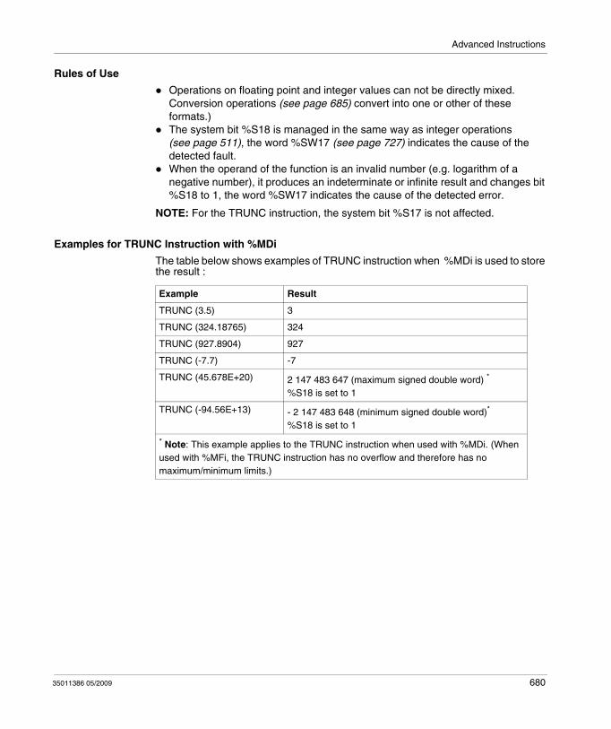
Advanced Instructions
Rules of Use
Operations on floating point and integer values can not be directly mixed. Conversion operations (see page 685) convert into one or other of these formats.)The system bit %S18 is managed in the same way as integer operations (see page 511), the word %SW17 (see page 727) indicates the cause of the detected fault.When the operand of the function is an invalid number (e.g. logarithm of a negative number), it produces an indeterminate or infinite result and changes bit %S18 to 1, the word %SW17 indicates the cause of the detected error.
NOTE: For the TRUNC instruction, the system bit %S17 is not affected.
Examples for TRUNC Instruction with %MDi
The table below shows examples of TRUNC instruction when %MDi is used to store the result :
Example Result
TRUNC (3.5) 3
TRUNC (324.18765) 324
TRUNC (927.8904) 927
TRUNC (-7.7) -7
TRUNC (45.678E+20) 2 147 483 647 (maximum signed double word) *
%S18 is set to 1
TRUNC (-94.56E+13) - 2 147 483 648 (minimum signed double word)*
%S18 is set to 1
* Note: This example applies to the TRUNC instruction when used with %MDi. (When used with %MFi, the TRUNC instruction has no overflow and therefore has no maximum/minimum limits.)
35011386 05/2009 680
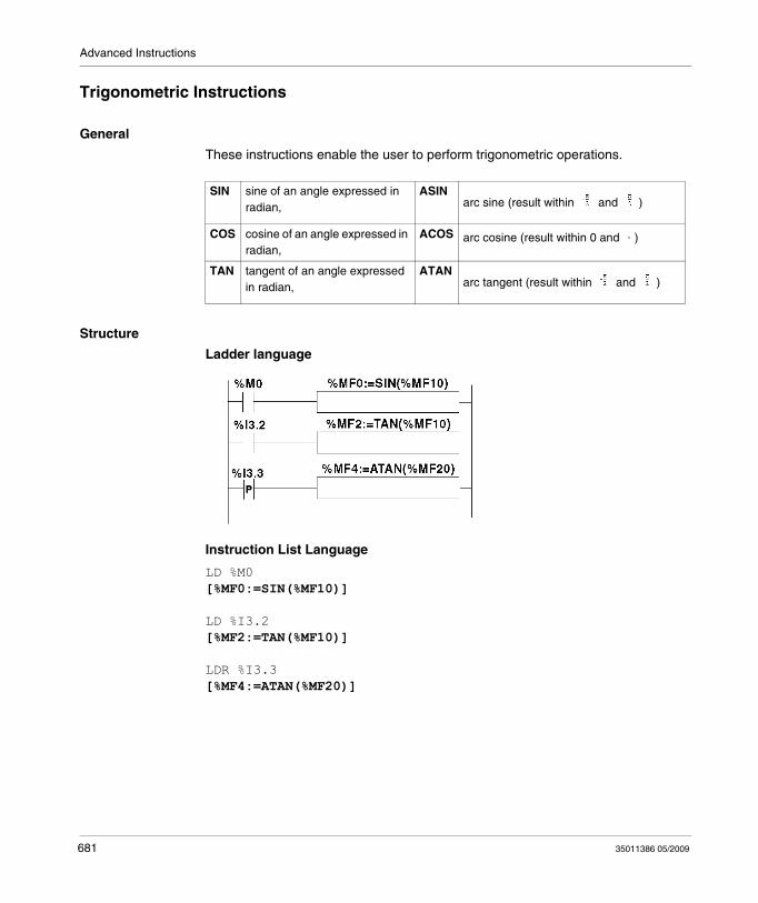
Advanced Instructions
Trigonometric Instructions
General
These instructions enable the user to perform trigonometric operations.
Structure
Ladder language
Instruction List Language
LD %M0[%MF0:=SIN(%MF10)]
LD %I3.2[%MF2:=TAN(%MF10)]
LDR %I3.3[%MF4:=ATAN(%MF20)]
SIN sine of an angle expressed in radian,
ASINarc sine (result within and )
COS cosine of an angle expressed in radian,
ACOS arc cosine (result within 0 and )
TAN tangent of an angle expressed in radian,
ATANarc tangent (result within and )
681 35011386 05/2009
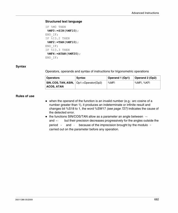
Advanced Instructions
Structured text language
IF %M0 THEN %MF0:=SIN(%MF10);END_IF;IF %I3.2 THEN %MF2:=TAN(%MF10);END_IF;IF %I3.3 THEN %MF4:=ATAN(%MF20);END_IF;
Syntax
Operators, operands and syntax of instructions for trigonometric operations
Rules of use
when the operand of the function is an invalid number (e.g.: arc cosine of a number greater than 1), it produces an indeterminate or infinite result and changes bit %S18 to 1, the word %SW17 (see page 727) indicates the cause of the detected error.the functions SIN/COS/TAN allow as a parameter an angle between and but their precision decreases progressively for the angles outside the period and because of the imprecision brought by the modulo carried out on the parameter before any operation.
Operators Syntax Operand 1 (Op1) Operand 2 (Op2)
SIN, COS, TAN, ASIN, ACOS, ATAN
Op1:=Operator(Op2) %MFi %MFi, %KFi
35011386 05/2009 682
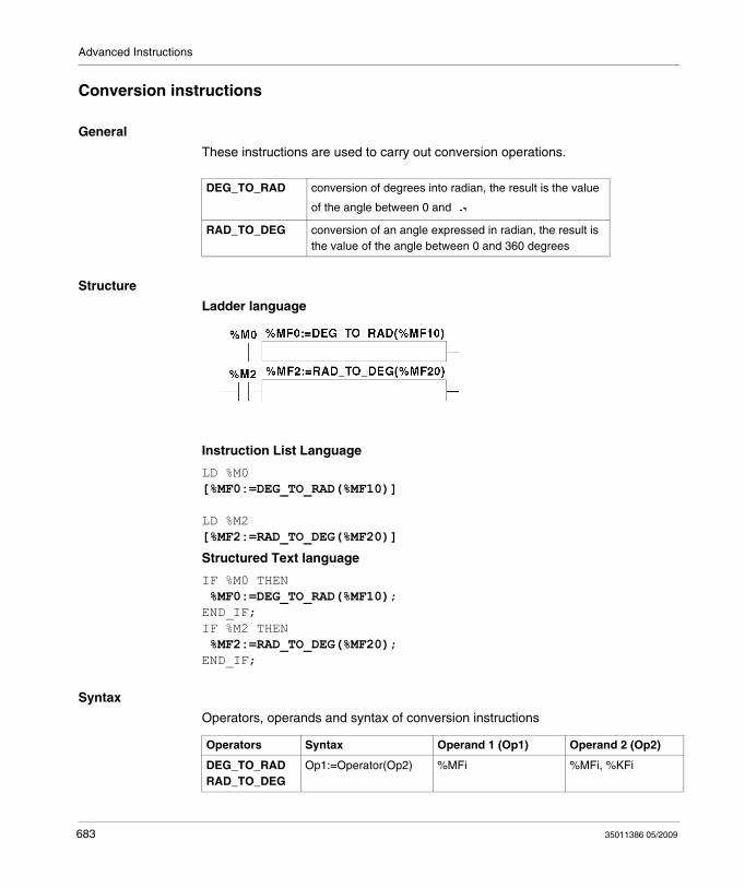
Advanced Instructions
Conversion instructions
General
These instructions are used to carry out conversion operations.
Structure
Ladder language
Instruction List Language
LD %M0[%MF0:=DEG_TO_RAD(%MF10)]
LD %M2[%MF2:=RAD_TO_DEG(%MF20)]
Structured Text language
IF %M0 THEN %MF0:=DEG_TO_RAD(%MF10);END_IF;IF %M2 THEN %MF2:=RAD_TO_DEG(%MF20);END_IF;
Syntax
Operators, operands and syntax of conversion instructions
DEG_TO_RAD conversion of degrees into radian, the result is the value
of the angle between 0 and
RAD_TO_DEG conversion of an angle expressed in radian, the result is the value of the angle between 0 and 360 degrees
Operators Syntax Operand 1 (Op1) Operand 2 (Op2)
DEG_TO_RAD RAD_TO_DEG
Op1:=Operator(Op2) %MFi %MFi, %KFi
683 35011386 05/2009

Advanced Instructions
Rules of use
The angle to be converted must be between -737280.0 and +737280.0 (for DEG_TO_RAD conversions) or between and (for RAD_TO_DEG conversions).
For values outside these ranges, the displayed result will be + 1.#QNAN, the %S18 and %SW17:X0 bits being set at 1.
35011386 05/2009 684
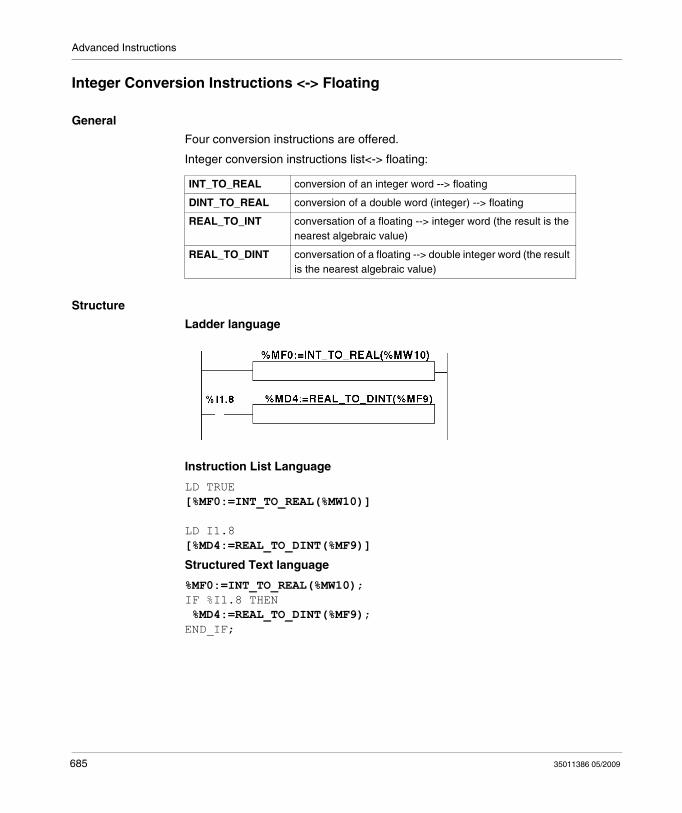
Advanced Instructions
Integer Conversion Instructions <-> Floating
General
Four conversion instructions are offered.
Integer conversion instructions list<-> floating:
Structure
Ladder language
Instruction List Language
LD TRUE[%MF0:=INT_TO_REAL(%MW10)]
LD I1.8[%MD4:=REAL_TO_DINT(%MF9)]
Structured Text language
%MF0:=INT_TO_REAL(%MW10);IF %I1.8 THEN %MD4:=REAL_TO_DINT(%MF9);END_IF;
INT_TO_REAL conversion of an integer word --> floating
DINT_TO_REAL conversion of a double word (integer) --> floating
REAL_TO_INT conversation of a floating --> integer word (the result is the nearest algebraic value)
REAL_TO_DINT conversation of a floating --> double integer word (the result is the nearest algebraic value)
685 35011386 05/2009

Advanced Instructions
Syntax
Operators and syntax (conversion of an integer word --> floating):
Operands (conversion of an integer word --> floating):
Example: integer word conversion --> floating: 147 --> 1.47e+02
Operators and syntax (double conversion of integer word --> floating):
Operands (double conversion of integer word --> floating):
Example:integer double word conversion --> floating: 68905000 --> 6.8905e+07
Operators and syntax (floating conversion --> integer word or integer double word):
Operators (floating conversion --> integer word or integer double word):
Example:
floating conversion --> integer word: 5978.6 --> 5979
floating conversion --> integer double word: -1235978.6 --> -1235979
NOTE: If during a real to integer (or real to integer double word) conversion the floating value is outside the limits of the word (or double word),bit %S18 is set to 1.
Operators Syntax
INT_TO_REAL Op1=INT_TO_REAL(Op2)
Operand 1 (Op1) Operand 2 (Op2)
%MFi %MWi,%KWi
Operators Syntax
DINT_TO_REAL Op1=DINT_TO_REAL(Op2)
Operand 1 (Op1) Operand 2 (Op2)
%MFi %MDi,%KDi
Operators Syntax
REAL_TO_INT Op1=Operator(Op2)
REAL_TO_DINT
Type Operand 1 (Op1) Operand 2 (Op2)
Words %MWi %MFi, %KFi
Double words %MDi %MFi, %KFi
35011386 05/2009 686
Advanced Instructions
Precision of Rounding
Standard IEEE 754 defines 4 rounding modes for floating operations.
The mode employed by the instructions above is the "rounded to the nearest" mode:
"if the nearest representable values are at an equal distance from the theoretical result, the value given will be the value whose low significance bit is equal to 0".
In certain cases, the result of the rounding can thus take a default value or an excess value.
For example:
Rounding of the value 10.5 -> 10
Rounding of the value 11.5 -> 12
687 35011386 05/2009
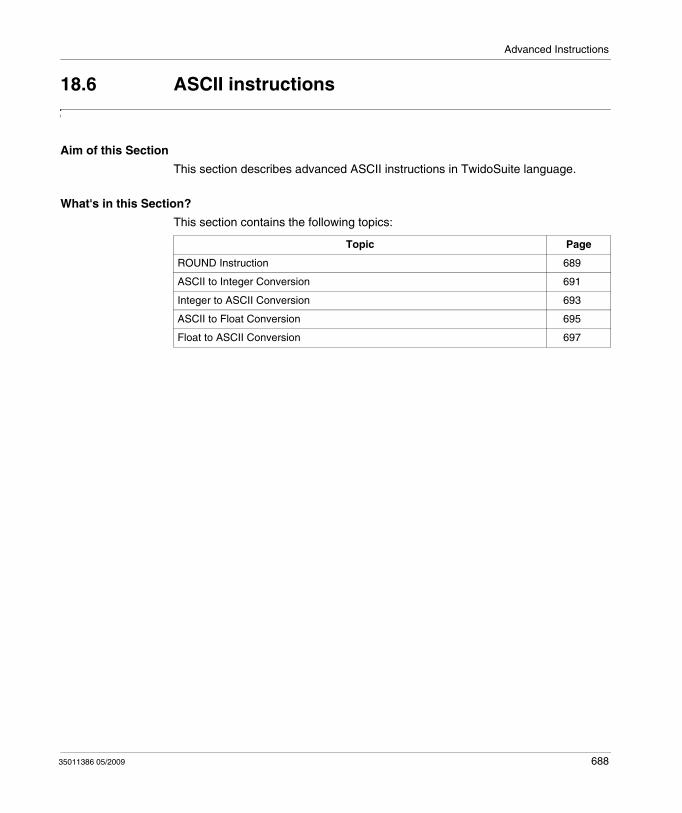
Advanced Instructions
18.6 ASCII instructions
Aim of this Section
This section describes advanced ASCII instructions in TwidoSuite language.
What's in this Section?
This section contains the following topics:
Topic Page
ROUND Instruction 689
ASCII to Integer Conversion 691
Integer to ASCII Conversion 693
ASCII to Float Conversion 695
Float to ASCII Conversion 697
35011386 05/2009 688
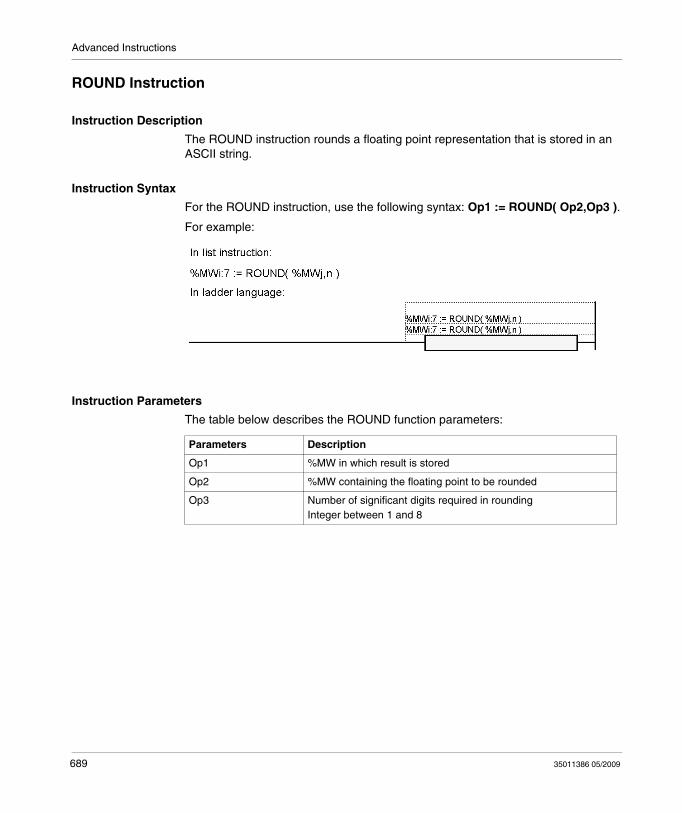
Advanced Instructions
ROUND Instruction
Instruction Description
The ROUND instruction rounds a floating point representation that is stored in an ASCII string.
Instruction Syntax
For the ROUND instruction, use the following syntax: Op1 := ROUND( Op2,Op3 ).
For example:
Instruction Parameters
The table below describes the ROUND function parameters:
Parameters Description
Op1 %MW in which result is stored
Op2 %MW containing the floating point to be rounded
Op3 Number of significant digits required in roundingInteger between 1 and 8
689 35011386 05/2009
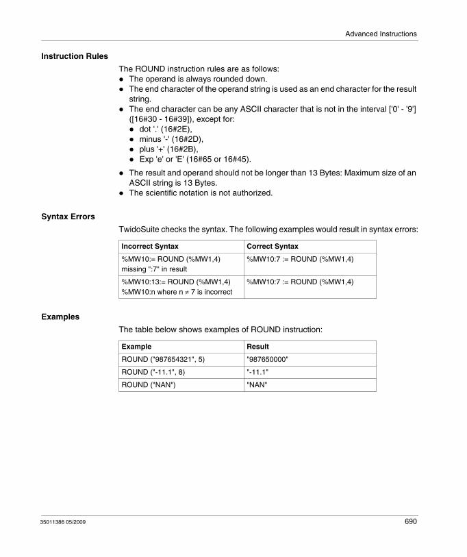
Advanced Instructions
Instruction Rules
The ROUND instruction rules are as follows:The operand is always rounded down.The end character of the operand string is used as an end character for the result string.The end character can be any ASCII character that is not in the interval ['0' - '9'] ([16#30 - 16#39]), except for:
dot '.' (16#2E),minus '-' (16#2D),plus '+' (16#2B),Exp 'e' or 'E' (16#65 or 16#45).
The result and operand should not be longer than 13 Bytes: Maximum size of an ASCII string is 13 Bytes.The scientific notation is not authorized.
Syntax Errors
TwidoSuite checks the syntax. The following examples would result in syntax errors:
Examples
The table below shows examples of ROUND instruction:
Incorrect Syntax Correct Syntax
%MW10:= ROUND (%MW1,4)missing ":7" in result
%MW10:7 := ROUND (%MW1,4)
%MW10:13:= ROUND (%MW1,4)%MW10:n where n ≠ 7 is incorrect
%MW10:7 := ROUND (%MW1,4)
Example Result
ROUND ("987654321", 5) "987650000"
ROUND ("-11.1", 8) "-11.1"
ROUND ("NAN") "NAN"
35011386 05/2009 690
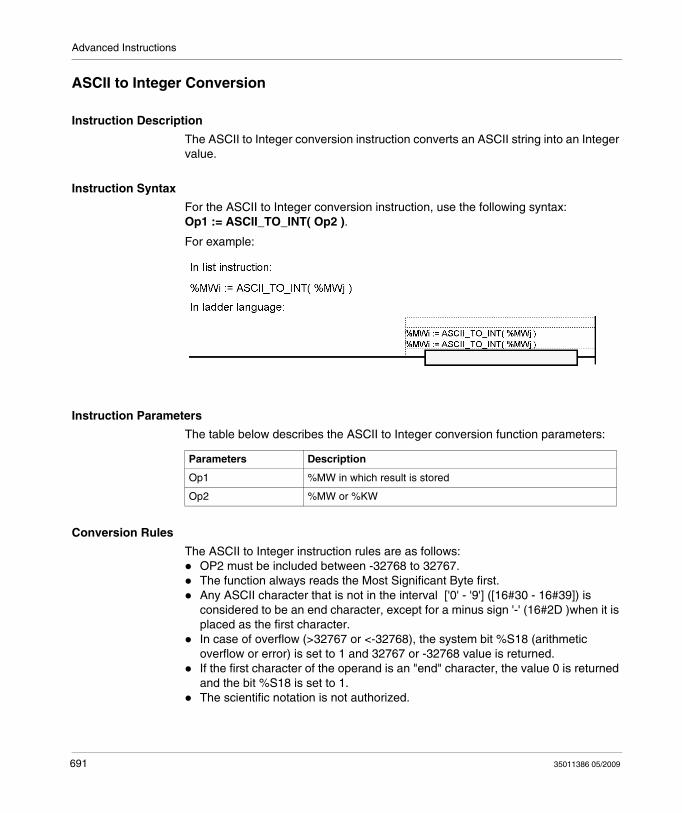
Advanced Instructions
ASCII to Integer Conversion
Instruction Description
The ASCII to Integer conversion instruction converts an ASCII string into an Integer value.
Instruction Syntax
For the ASCII to Integer conversion instruction, use the following syntax: Op1 := ASCII_TO_INT( Op2 ).
For example:
Instruction Parameters
The table below describes the ASCII to Integer conversion function parameters:
Conversion Rules
The ASCII to Integer instruction rules are as follows:OP2 must be included between -32768 to 32767.The function always reads the Most Significant Byte first.Any ASCII character that is not in the interval ['0' - '9'] ([16#30 - 16#39]) is considered to be an end character, except for a minus sign '-' (16#2D )when it is placed as the first character.In case of overflow (>32767 or <-32768), the system bit %S18 (arithmetic overflow or error) is set to 1 and 32767 or -32768 value is returned.If the first character of the operand is an "end" character, the value 0 is returned and the bit %S18 is set to 1.The scientific notation is not authorized.
Parameters Description
Op1 %MW in which result is stored
Op2 %MW or %KW
691 35011386 05/2009
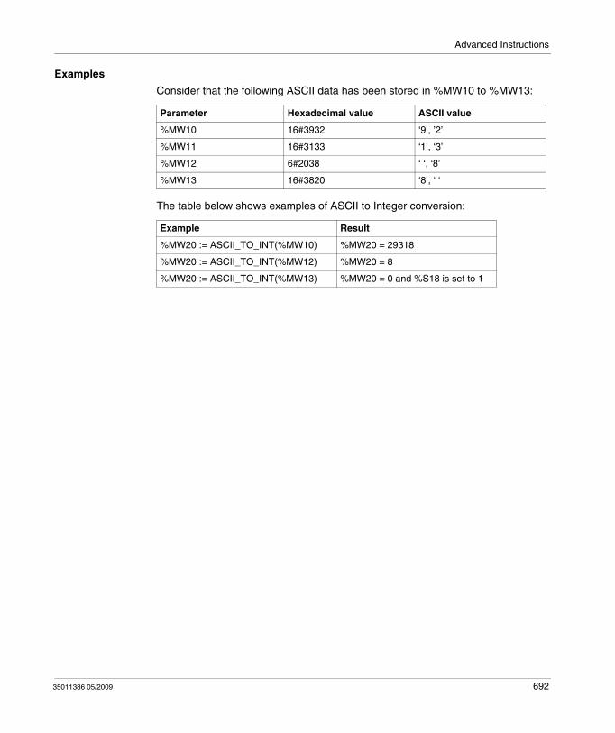
Advanced Instructions
Examples
Consider that the following ASCII data has been stored in %MW10 to %MW13:
The table below shows examples of ASCII to Integer conversion:
Parameter Hexadecimal value ASCII value
%MW10 16#3932 ‘9’, ’2’
%MW11 16#3133 ‘1’, ‘3’
%MW12 6#2038 ‘ ‘, ‘8’
%MW13 16#3820 ‘8’, ‘ ‘
Example Result
%MW20 := ASCII_TO_INT(%MW10) %MW20 = 29318
%MW20 := ASCII_TO_INT(%MW12) %MW20 = 8
%MW20 := ASCII_TO_INT(%MW13) %MW20 = 0 and %S18 is set to 1
35011386 05/2009 692
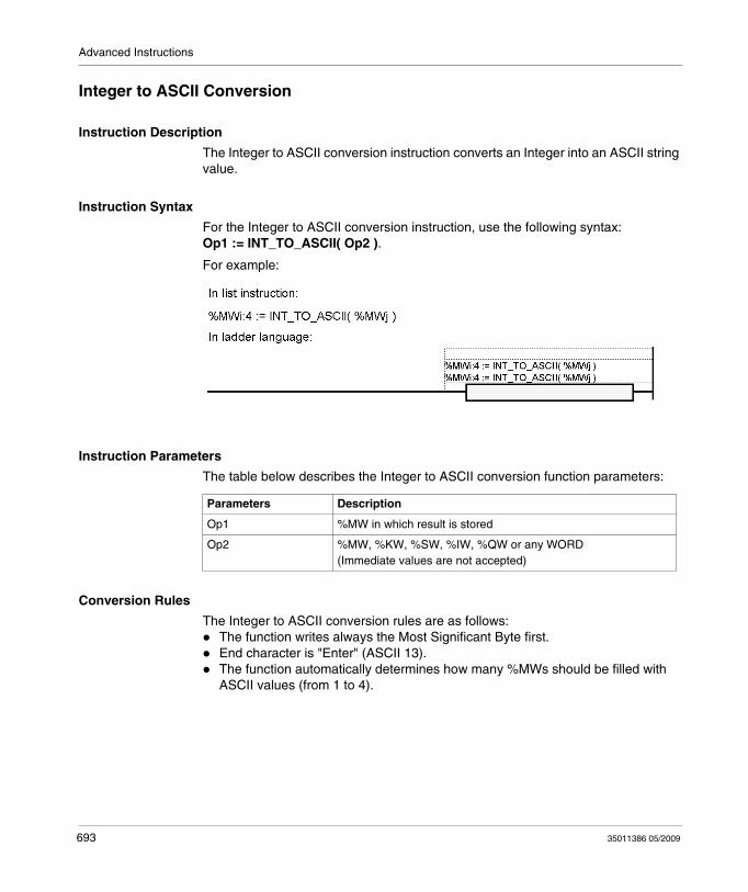
Advanced Instructions
Integer to ASCII Conversion
Instruction Description
The Integer to ASCII conversion instruction converts an Integer into an ASCII string value.
Instruction Syntax
For the Integer to ASCII conversion instruction, use the following syntax: Op1 := INT_TO_ASCII( Op2 ).
For example:
Instruction Parameters
The table below describes the Integer to ASCII conversion function parameters:
Conversion Rules
The Integer to ASCII conversion rules are as follows:The function writes always the Most Significant Byte first.End character is "Enter" (ASCII 13).The function automatically determines how many %MWs should be filled with ASCII values (from 1 to 4).
Parameters Description
Op1 %MW in which result is stored
Op2 %MW, %KW, %SW, %IW, %QW or any WORD(Immediate values are not accepted)
693 35011386 05/2009
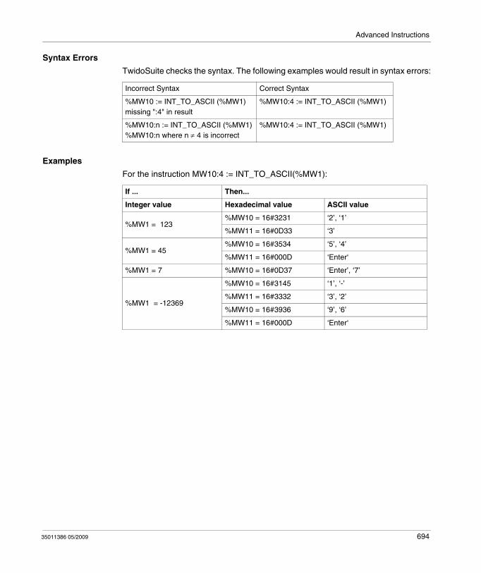
Advanced Instructions
Syntax Errors
TwidoSuite checks the syntax. The following examples would result in syntax errors:
Examples
For the instruction MW10:4 := INT_TO_ASCII(%MW1):
Incorrect Syntax Correct Syntax
%MW10 := INT_TO_ASCII (%MW1)missing ":4" in result
%MW10:4 := INT_TO_ASCII (%MW1)
%MW10:n := INT_TO_ASCII (%MW1)%MW10:n where n ≠ 4 is incorrect
%MW10:4 := INT_TO_ASCII (%MW1)
If ... Then...
Integer value Hexadecimal value ASCII value
%MW1 = 123%MW10 = 16#3231 ‘2’, ‘1’
%MW11 = 16#0D33 ‘3’
%MW1 = 45%MW10 = 16#3534 ‘5’, ‘4’
%MW11 = 16#000D ‘Enter‘
%MW1 = 7 %MW10 = 16#0D37 ‘Enter’, ‘7’
%MW1 = -12369
%MW10 = 16#3145 ‘1’, ‘-’
%MW11 = 16#3332 ‘3’, ‘2’
%MW10 = 16#3936 ‘9’, ‘6’
%MW11 = 16#000D ‘Enter‘
35011386 05/2009 694
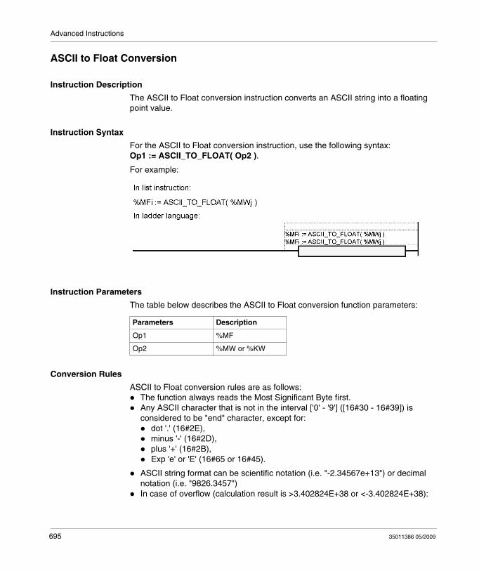
Advanced Instructions
ASCII to Float Conversion
Instruction Description
The ASCII to Float conversion instruction converts an ASCII string into a floating point value.
Instruction Syntax
For the ASCII to Float conversion instruction, use the following syntax: Op1 := ASCII_TO_FLOAT( Op2 ).
For example:
Instruction Parameters
The table below describes the ASCII to Float conversion function parameters:
Conversion Rules
ASCII to Float conversion rules are as follows:The function always reads the Most Significant Byte first.Any ASCII character that is not in the interval ['0' - '9'] ([16#30 - 16#39]) is considered to be "end" character, except for:
dot '.' (16#2E),minus '-' (16#2D),plus '+' (16#2B),Exp 'e' or 'E' (16#65 or 16#45).
ASCII string format can be scientific notation (i.e. "-2.34567e+13") or decimal notation (i.e. "9826.3457")In case of overflow (calculation result is >3.402824E+38 or <-3.402824E+38):
Parameters Description
Op1 %MF
Op2 %MW or %KW
695 35011386 05/2009
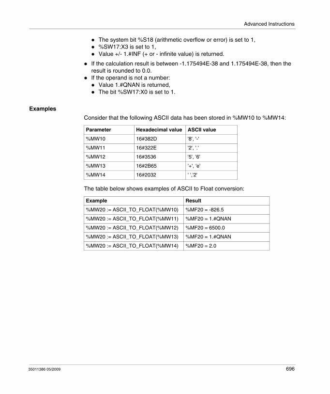
Advanced Instructions
The system bit %S18 (arithmetic overflow or error) is set to 1,%SW17:X3 is set to 1,Value +/- 1.#INF (+ or - infinite value) is returned.
If the calculation result is between -1.175494E-38 and 1.175494E-38, then the result is rounded to 0.0.If the operand is not a number:
Value 1.#QNAN is returned,The bit %SW17:X0 is set to 1.
Examples
Consider that the following ASCII data has been stored in %MW10 to %MW14:
The table below shows examples of ASCII to Float conversion:
Parameter Hexadecimal value ASCII value
%MW10 16#382D '8', '-'
%MW11 16#322E '2', '.'
%MW12 16#3536 '5', '6'
%MW13 16#2B65 '+', 'e'
%MW14 16#2032 ' ','2'
Example Result
%MW20 := ASCII_TO_FLOAT(%MW10) %MF20 = -826.5
%MW20 := ASCII_TO_FLOAT(%MW11) %MF20 = 1.#QNAN
%MW20 := ASCII_TO_FLOAT(%MW12) %MF20 = 6500.0
%MW20 := ASCII_TO_FLOAT(%MW13) %MF20 = 1.#QNAN
%MW20 := ASCII_TO_FLOAT(%MW14) %MF20 = 2.0
35011386 05/2009 696
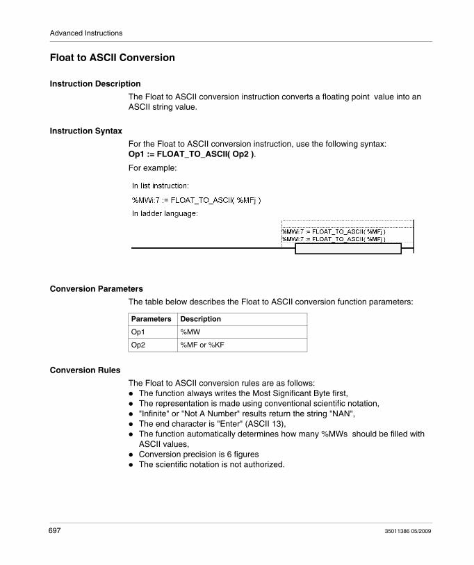
Advanced Instructions
Float to ASCII Conversion
Instruction Description
The Float to ASCII conversion instruction converts a floating point value into an ASCII string value.
Instruction Syntax
For the Float to ASCII conversion instruction, use the following syntax: Op1 := FLOAT_TO_ASCII( Op2 ).
For example:
Conversion Parameters
The table below describes the Float to ASCII conversion function parameters:
Conversion Rules
The Float to ASCII conversion rules are as follows:The function always writes the Most Significant Byte first,The representation is made using conventional scientific notation,"Infinite" or "Not A Number" results return the string "NAN",The end character is "Enter" (ASCII 13),The function automatically determines how many %MWs should be filled with ASCII values,Conversion precision is 6 figuresThe scientific notation is not authorized.
Parameters Description
Op1 %MW
Op2 %MF or %KF
697 35011386 05/2009
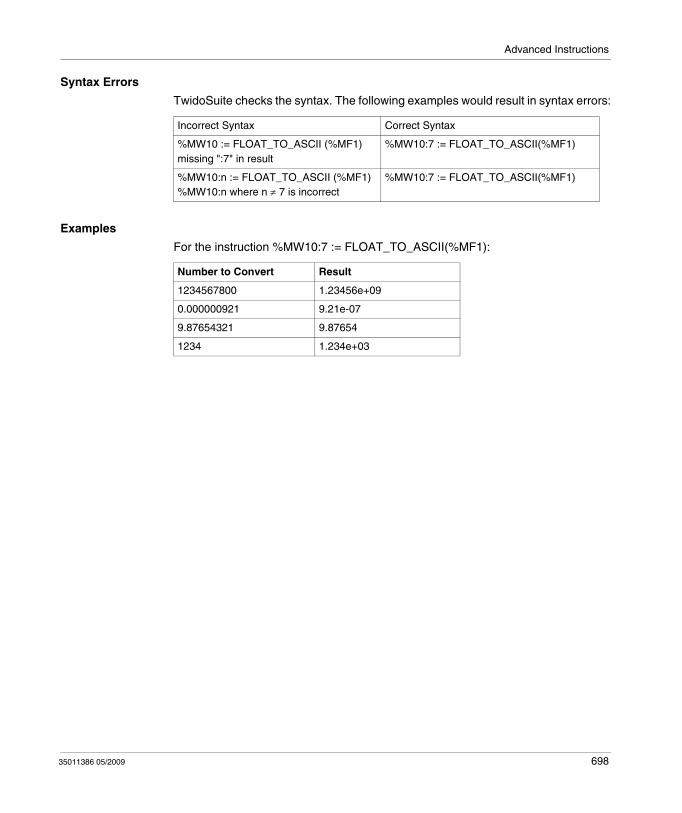
Advanced Instructions
Syntax Errors
TwidoSuite checks the syntax. The following examples would result in syntax errors:
Examples
For the instruction %MW10:7 := FLOAT_TO_ASCII(%MF1):
Incorrect Syntax Correct Syntax
%MW10 := FLOAT_TO_ASCII (%MF1)missing ":7" in result
%MW10:7 := FLOAT_TO_ASCII(%MF1)
%MW10:n := FLOAT_TO_ASCII (%MF1)%MW10:n where n ≠ 7 is incorrect
%MW10:7 := FLOAT_TO_ASCII(%MF1)
Number to Convert Result
1234567800 1.23456e+09
0.000000921 9.21e-07
9.87654321 9.87654
1234 1.234e+03
35011386 05/2009 698
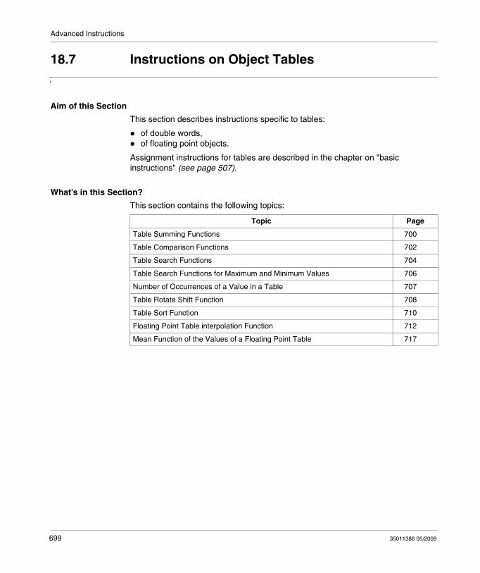
Advanced Instructions
18.7 Instructions on Object Tables
Aim of this Section
This section describes instructions specific to tables:
of double words,of floating point objects.
Assignment instructions for tables are described in the chapter on "basic instructions" (see page 507).
What's in this Section?
This section contains the following topics:
Topic Page
Table Summing Functions 700
Table Comparison Functions 702
Table Search Functions 704
Table Search Functions for Maximum and Minimum Values 706
Number of Occurrences of a Value in a Table 707
Table Rotate Shift Function 708
Table Sort Function 710
Floating Point Table interpolation Function 712
Mean Function of the Values of a Floating Point Table 717
699 35011386 05/2009
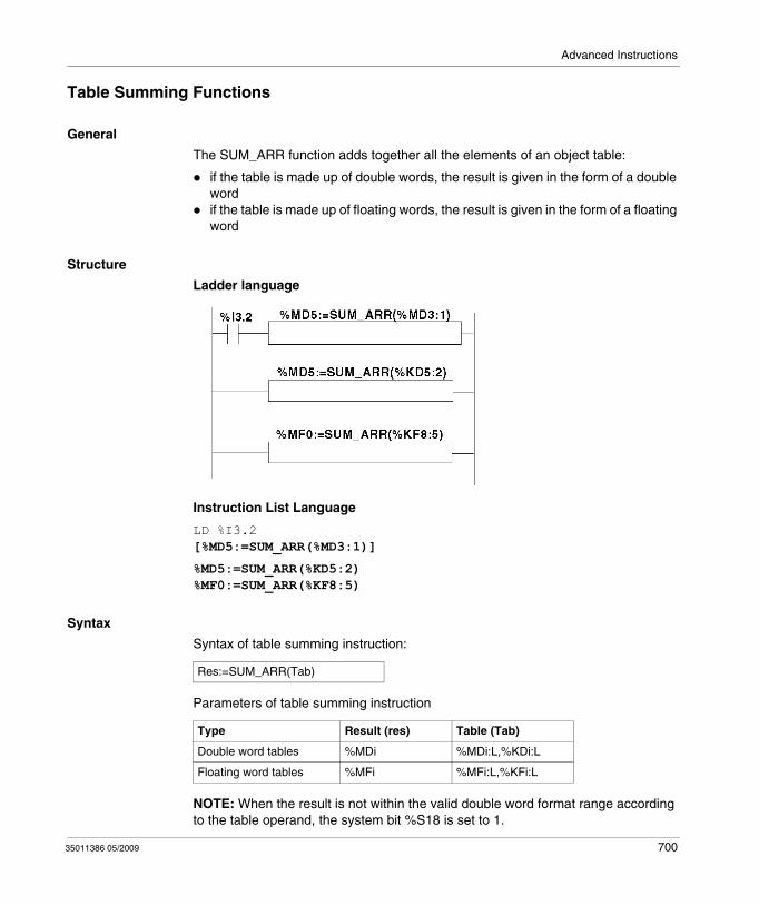
Advanced Instructions
Table Summing Functions
General
The SUM_ARR function adds together all the elements of an object table:
if the table is made up of double words, the result is given in the form of a double word if the table is made up of floating words, the result is given in the form of a floating word
Structure
Ladder language
Instruction List Language
LD %I3.2[%MD5:=SUM_ARR(%MD3:1)]
%MD5:=SUM_ARR(%KD5:2) %MF0:=SUM_ARR(%KF8:5)
Syntax
Syntax of table summing instruction:
Parameters of table summing instruction
NOTE: When the result is not within the valid double word format range according to the table operand, the system bit %S18 is set to 1.
Res:=SUM_ARR(Tab)
Type Result (res) Table (Tab)
Double word tables %MDi %MDi:L,%KDi:L
Floating word tables %MFi %MFi:L,%KFi:L
35011386 05/2009 700

Advanced Instructions
Example
%MD4:=SUM(%MD30:4)
where %MD30=10, %MD32=20, %MD34=30, %MD36=40
%MD4:=10+20+30+40
701 35011386 05/2009
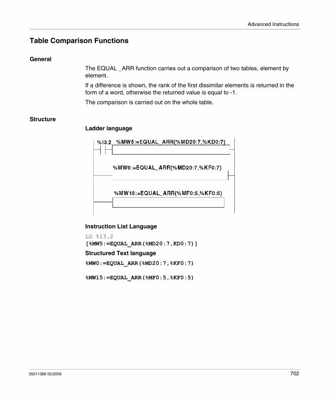
Advanced Instructions
Table Comparison Functions
General
The EQUAL _ARR function carries out a comparison of two tables, element by element.
If a difference is shown, the rank of the first dissimilar elements is returned in the form of a word, otherwise the returned value is equal to -1.
The comparison is carried out on the whole table.
Structure
Ladder language
Instruction List Language
LD %I3.2[%MW5:=EQUAL_ARR(%MD20:7,KD0:7)]
Structured Text language
%MW0:=EQUAL_ARR(%MD20:7,%KF0:7)
%MW15:=EQUAL_ARR(%MF0:5,%KF0:5)
35011386 05/2009 702
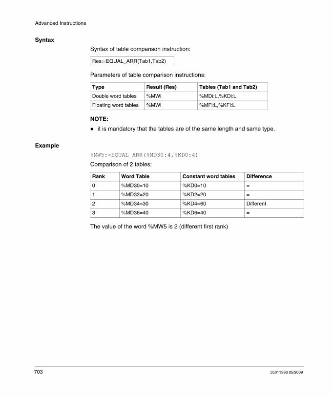
Advanced Instructions
Syntax
Syntax of table comparison instruction:
Parameters of table comparison instructions:
NOTE:
it is mandatory that the tables are of the same length and same type.
Example
%MW5:=EQUAL_ARR(%MD30:4,%KD0:4)
Comparison of 2 tables:
The value of the word %MW5 is 2 (different first rank)
Res:=EQUAL_ARR(Tab1,Tab2)
Type Result (Res) Tables (Tab1 and Tab2)
Double word tables %MWi %MDi:L,%KDi:L
Floating word tables %MWi %MFi:L,%KFi:L
Rank Word Table Constant word tables Difference
0 %MD30=10 %KD0=10 =
1 %MD32=20 %KD2=20 =
2 %MD34=30 %KD4=60 Different
3 %MD36=40 %KD6=40 =
703 35011386 05/2009
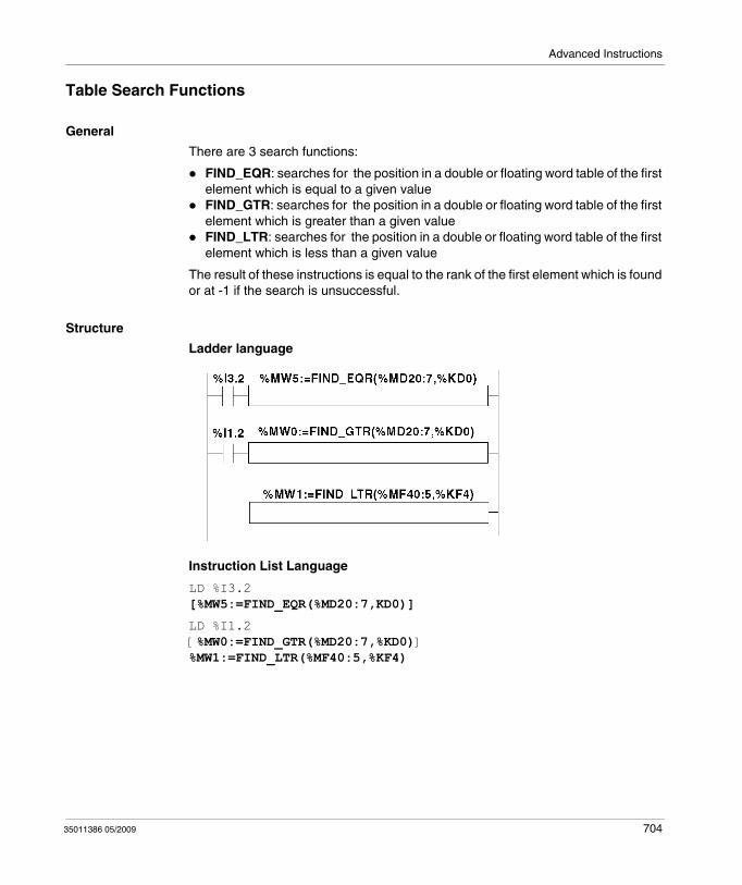
Advanced Instructions
Table Search Functions
General
There are 3 search functions:
FIND_EQR: searches for the position in a double or floating word table of the first element which is equal to a given valueFIND_GTR: searches for the position in a double or floating word table of the first element which is greater than a given valueFIND_LTR: searches for the position in a double or floating word table of the first element which is less than a given value
The result of these instructions is equal to the rank of the first element which is found or at -1 if the search is unsuccessful.
Structure
Ladder language
Instruction List Language
LD %I3.2[%MW5:=FIND_EQR(%MD20:7,KD0)]
LD %I1.2[%MW0:=FIND_GTR(%MD20:7,%KD0)]%MW1:=FIND_LTR(%MF40:5,%KF4)
35011386 05/2009 704
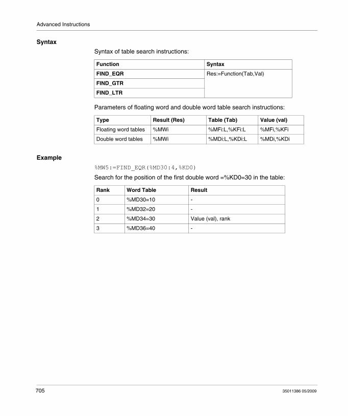
Advanced Instructions
Syntax
Syntax of table search instructions:
Parameters of floating word and double word table search instructions:
Example
%MW5:=FIND_EQR(%MD30:4,%KD0)
Search for the position of the first double word =%KD0=30 in the table:
Function Syntax
FIND_EQR Res:=Function(Tab,Val)
FIND_GTR
FIND_LTR
Type Result (Res) Table (Tab) Value (val)
Floating word tables %MWi %MFi:L,%KFi:L %MFi,%KFi
Double word tables %MWi %MDi:L,%KDi:L %MDi,%KDi
Rank Word Table Result
0 %MD30=10 -
1 %MD32=20 -
2 %MD34=30 Value (val), rank
3 %MD36=40 -
705 35011386 05/2009
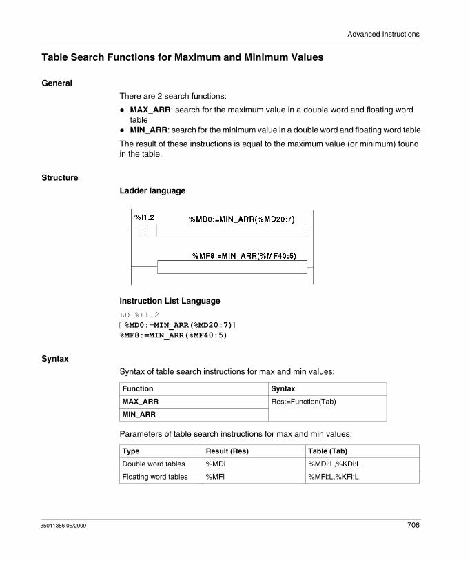
Advanced Instructions
Table Search Functions for Maximum and Minimum Values
General
There are 2 search functions:
MAX_ARR: search for the maximum value in a double word and floating word tableMIN_ARR: search for the minimum value in a double word and floating word table
The result of these instructions is equal to the maximum value (or minimum) found in the table.
Structure
Ladder language
Instruction List Language
LD %I1.2[%MD0:=MIN_ARR(%MD20:7)]%MF8:=MIN_ARR(%MF40:5)
Syntax
Syntax of table search instructions for max and min values:
Parameters of table search instructions for max and min values:
Function Syntax
MAX_ARR Res:=Function(Tab)
MIN_ARR
Type Result (Res) Table (Tab)
Double word tables %MDi %MDi:L,%KDi:L
Floating word tables %MFi %MFi:L,%KFi:L
35011386 05/2009 706
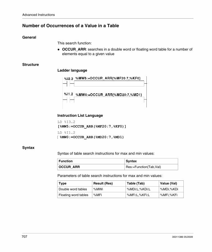
Advanced Instructions
Number of Occurrences of a Value in a Table
General
This search function:
OCCUR_ARR: searches in a double word or floating word table for a number of elements equal to a given value
Structure
Ladder language
Instruction List Language
LD %I3.2[%MW5:=OCCUR_ARR(%MF20:7,%KF0)]
LD %I1.2[%MW0:=OCCUR_ARR(%MD20:7,%MD1)
Syntax
Syntax of table search instructions for max and min values:
Parameters of table search instructions for max and min values:
Function Syntax
OCCUR_ARR Res:=Function(Tab,Val)
Type Result (Res) Table (Tab) Value (Val)
Double word tables %MWi %MDi:L,%KDi:L %MDi,%KDi
Floating word tables %MFi %MFi:L,%KFi:L %MFi,%KFi
707 35011386 05/2009
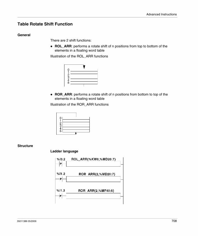
Advanced Instructions
Table Rotate Shift Function
General
There are 2 shift functions:
ROL_ARR: performs a rotate shift of n positions from top to bottom of the elements in a floating word table
Illustration of the ROL_ARR functions
ROR_ARR: performs a rotate shift of n positions from bottom to top of the elements in a floating word table
Illustration of the ROR_ARR functions
Structure
Ladder language
35011386 05/2009 708
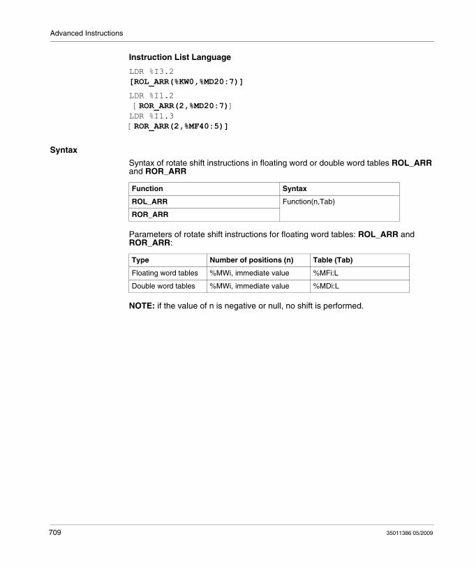
Advanced Instructions
Instruction List Language
LDR %I3.2[ROL_ARR(%KW0,%MD20:7)]
LDR %I1.2 [ROR_ARR(2,%MD20:7)]LDR %I1.3[ROR_ARR(2,%MF40:5)]
Syntax
Syntax of rotate shift instructions in floating word or double word tables ROL_ARR and ROR_ARR
Parameters of rotate shift instructions for floating word tables: ROL_ARR and ROR_ARR:
NOTE: if the value of n is negative or null, no shift is performed.
Function Syntax
ROL_ARR Function(n,Tab)
ROR_ARR
Type Number of positions (n) Table (Tab)
Floating word tables %MWi, immediate value %MFi:L
Double word tables %MWi, immediate value %MDi:L
709 35011386 05/2009
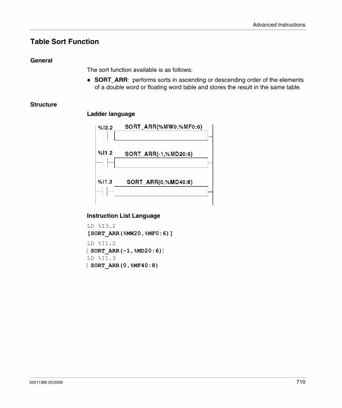
Advanced Instructions
Table Sort Function
General
The sort function available is as follows:
SORT_ARR: performs sorts in ascending or descending order of the elements of a double word or floating word table and stores the result in the same table.
Structure
Ladder language
Instruction List Language
LD %I3.2[SORT_ARR(%MW20,%MF0:6)]
LD %I1.2[SORT_ARR(-1,%MD20:6)]LD %I1.3[SORT_ARR(0,%MF40:8)
35011386 05/2009 710
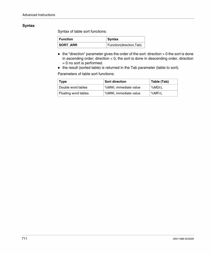
Advanced Instructions
Syntax
Syntax of table sort functions:
the "direction" parameter gives the order of the sort: direction > 0 the sort is done in ascending order; direction < 0, the sort is done in descending order, direction = 0 no sort is performed.the result (sorted table) is returned in the Tab parameter (table to sort).
Parameters of table sort functions:
Function Syntax
SORT_ARR Function(direction,Tab)
Type Sort direction Table (Tab)
Double word tables %MWi, immediate value %MDi:L
Floating word tables %MWi, immediate value %MFi:L
711 35011386 05/2009
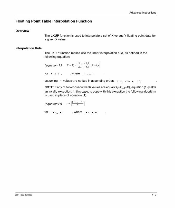
Advanced Instructions
Floating Point Table interpolation Function
Overview
The LKUP function is used to interpolate a set of X versus Y floating point data for a given X value.
Interpolation Rule
The LKUP function makes use the linear interpolation rule, as defined in the following equation:
(equation 1:)
for , where ;
assuming values are ranked in ascending order: .
NOTE: If any of two consecutive Xi values are equal (Xi=Xi+1=X), equation (1) yields an invalid exception. In this case, to cope with this exception the following algorithm is used in place of equation (1):
(equation 2:)
for , where .
35011386 05/2009 712
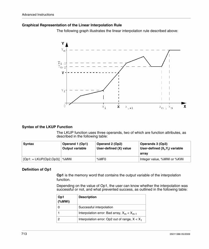
Advanced Instructions
Graphical Representation of the Linear Interpolation Rule
The following graph illustrates the linear interpolation rule described above:
Syntax of the LKUP Function
The LKUP function uses three operands, two of which are function attributes, as described in the following table:
Definition of Op1
Op1 is the memory word that contains the output variable of the interpolation function.
Depending on the value of Op1, the user can know whether the interpolation was successful or not, and what prevented success, as outlined in the following table:
Syntax Operand 1 (Op1)Output variable
Operand 2 (Op2)User-defined (X) value
Operands 3 (Op3)User-defined (Xi,Yi) variable
array
[Op1: = LKUP(Op2,Op3)] %MWi %MF0 Integer value, %MWi or %KWi
Op1 (%MWi)
Description
0 Successful interpolation
1 Interpolation error: Bad array, Xm < Xm-1
2 Interpolation error: Op2 out of range, X < X1
713 35011386 05/2009
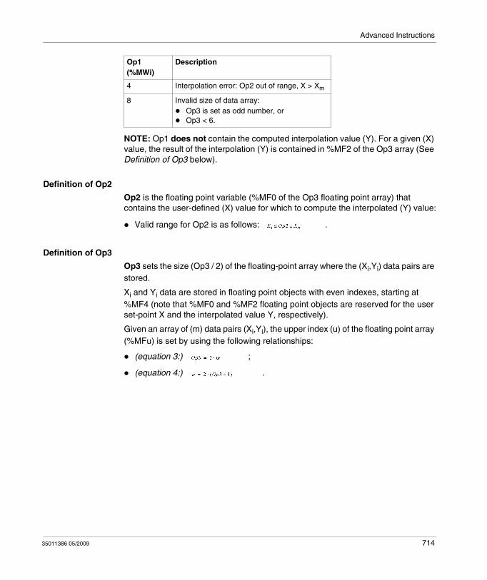
Advanced Instructions
NOTE: Op1 does not contain the computed interpolation value (Y). For a given (X) value, the result of the interpolation (Y) is contained in %MF2 of the Op3 array (See Definition of Op3 below).
Definition of Op2
Op2 is the floating point variable (%MF0 of the Op3 floating point array) that contains the user-defined (X) value for which to compute the interpolated (Y) value:
Valid range for Op2 is as follows: .
Definition of Op3
Op3 sets the size (Op3 / 2) of the floating-point array where the (Xi,Yi) data pairs are stored.
Xi and Yi data are stored in floating point objects with even indexes, starting at %MF4 (note that %MF0 and %MF2 floating point objects are reserved for the user set-point X and the interpolated value Y, respectively).
Given an array of (m) data pairs (Xi,Yi), the upper index (u) of the floating point array (%MFu) is set by using the following relationships:
(equation 3:) ;
(equation 4:) .
4 Interpolation error: Op2 out of range, X > Xm
8 Invalid size of data array:Op3 is set as odd number, orOp3 < 6.
Op1 (%MWi)
Description
35011386 05/2009 714
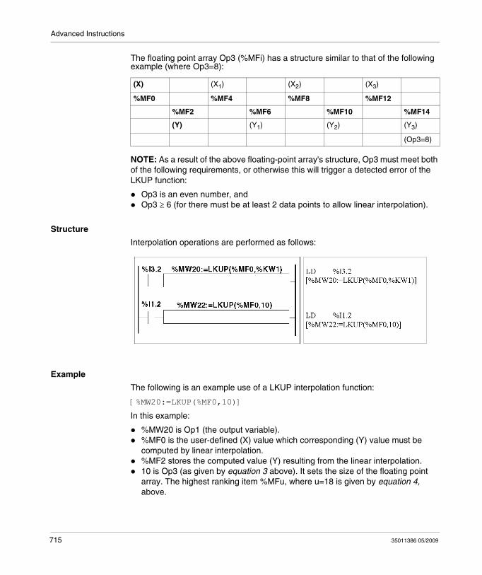
Advanced Instructions
The floating point array Op3 (%MFi) has a structure similar to that of the following example (where Op3=8):
NOTE: As a result of the above floating-point array's structure, Op3 must meet both of the following requirements, or otherwise this will trigger a detected error of the LKUP function:
Op3 is an even number, andOp3 ≥ 6 (for there must be at least 2 data points to allow linear interpolation).
Structure
Interpolation operations are performed as follows:
Example
The following is an example use of a LKUP interpolation function:
[%MW20:=LKUP(%MF0,10)]
In this example:
%MW20 is Op1 (the output variable).%MF0 is the user-defined (X) value which corresponding (Y) value must be computed by linear interpolation.%MF2 stores the computed value (Y) resulting from the linear interpolation.10 is Op3 (as given by equation 3 above). It sets the size of the floating point array. The highest ranking item %MFu, where u=18 is given by equation 4, above.
(X) (X1) (X2) (X3)
%MF0 %MF4 %MF8 %MF12
%MF2 %MF6 %MF10 %MF14
(Y) (Y1) (Y2) (Y3)
(Op3=8)
715 35011386 05/2009

Advanced Instructions
There are 4 pairs of data points stored in Op3 array [%MF4..%MF18]:%MF4 contains X1,%MF6 contains Y1.%MF8 contains X2,%MF10 contains Y2.%MF12 contains X3,%MF14 contains Y3.%MF16 contains X4,%MF18 contains Y4.
35011386 05/2009 716
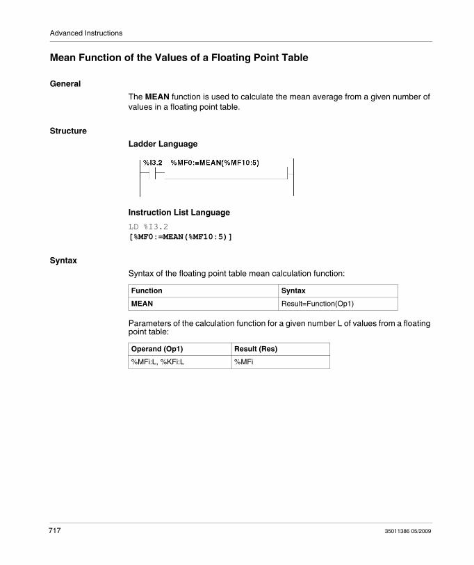
Advanced Instructions
Mean Function of the Values of a Floating Point Table
General
The MEAN function is used to calculate the mean average from a given number of values in a floating point table.
Structure
Ladder Language
Instruction List Language
LD %I3.2[%MF0:=MEAN(%MF10:5)]
Syntax
Syntax of the floating point table mean calculation function:
Parameters of the calculation function for a given number L of values from a floating point table:
Function Syntax
MEAN Result=Function(Op1)
Operand (Op1) Result (Res)
%MFi:L, %KFi:L %MFi
717 35011386 05/2009
35011386 05/2009
19
System Bits and Words
35011386 05/2009
System Bits and System Words
Subject of this Chapter
This chapter provides an overview of the system bits and system words that can be used to create control programs for Twido controllers.
What's in this Chapter?
This chapter contains the following topics:
Topic Page
System Bits (%S) 719
System Words (%SW) 727
718
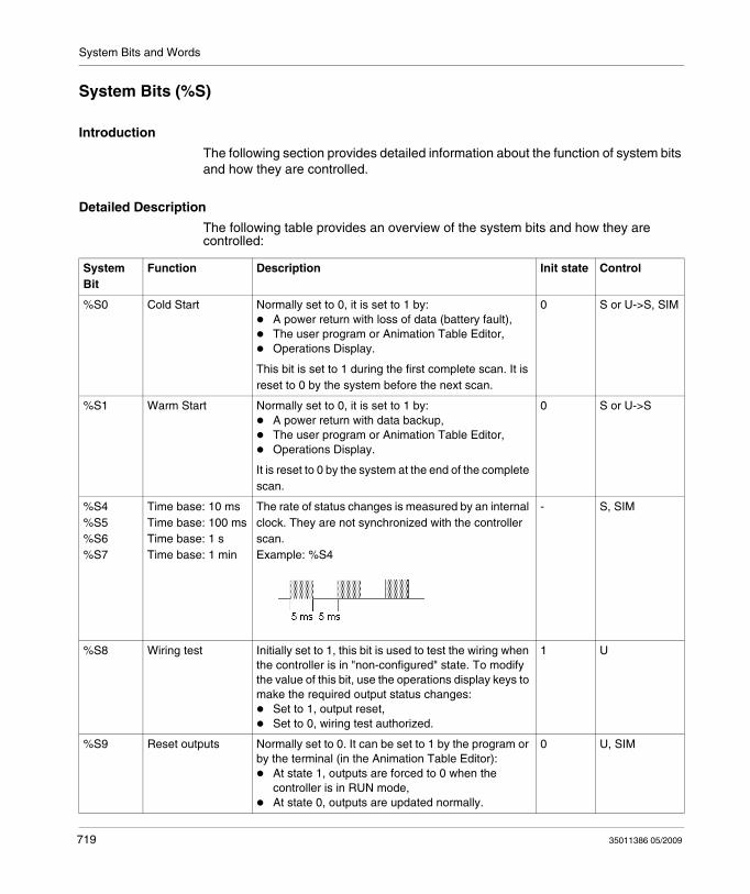
System Bits and Words
System Bits (%S)
Introduction
The following section provides detailed information about the function of system bits and how they are controlled.
Detailed Description
The following table provides an overview of the system bits and how they are controlled:
System Bit
Function Description Init state Control
%S0 Cold Start Normally set to 0, it is set to 1 by:A power return with loss of data (battery fault),The user program or Animation Table Editor,Operations Display.
This bit is set to 1 during the first complete scan. It is reset to 0 by the system before the next scan.
0 S or U->S, SIM
%S1 Warm Start Normally set to 0, it is set to 1 by:A power return with data backup,The user program or Animation Table Editor,Operations Display.
It is reset to 0 by the system at the end of the complete scan.
0 S or U->S
%S4%S5%S6%S7
Time base: 10 msTime base: 100 msTime base: 1 sTime base: 1 min
The rate of status changes is measured by an internal clock. They are not synchronized with the controller scan. Example: %S4
- S, SIM
%S8 Wiring test Initially set to 1, this bit is used to test the wiring when the controller is in "non-configured" state. To modify the value of this bit, use the operations display keys to make the required output status changes:
Set to 1, output reset,Set to 0, wiring test authorized.
1 U
%S9 Reset outputs Normally set to 0. It can be set to 1 by the program or by the terminal (in the Animation Table Editor):
At state 1, outputs are forced to 0 when the controller is in RUN mode,At state 0, outputs are updated normally.
0 U, SIM
719 35011386 05/2009
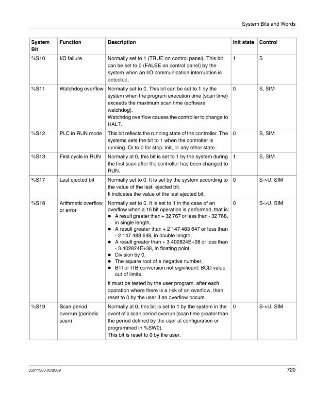
System Bits and Words
%S10 I/O failure Normally set to 1 (TRUE on control panel). This bit can be set to 0 (FALSE on control panel) by the system when an I/O communication interruption is detected.
1 S
%S11 Watchdog overflow Normally set to 0. This bit can be set to 1 by the system when the program execution time (scan time) exceeds the maximum scan time (software watchdog). Watchdog overflow causes the controller to change to HALT.
0 S, SIM
%S12 PLC in RUN mode This bit reflects the running state of the controller. The systems sets the bit to 1 when the controller is running. Or to 0 for stop, init, or any other state.
0 S, SIM
%S13 First cycle in RUN Normally at 0, this bit is set to 1 by the system during the first scan after the controller has been changed to RUN.
1 S, SIM
%S17 Last ejected bit Normally set to 0. It is set by the system according to the value of the last ejected bit.It indicates the value of the last ejected bit.
0 S->U, SIM
%S18 Arithmetic overflow or error
Normally set to 0. It is set to 1 in the case of an overflow when a 16 bit operation is performed, that is:
A result greater than + 32 767 or less than - 32 768, in single length,A result greater than + 2 147 483 647 or less than - 2 147 483 648, in double length,A result greater than + 3.402824E+38 or less than - 3.402824E+38, in floating point,Division by 0,The square root of a negative number,BTI or ITB conversion not significant: BCD value out of limits.
It must be tested by the user program, after each operation where there is a risk of an overflow, then reset to 0 by the user if an overflow occurs.
0 S->U, SIM
%S19 Scan period overrun (periodic scan)
Normally at 0, this bit is set to 1 by the system in the event of a scan period overrun (scan time greater than the period defined by the user at configuration or programmed in %SW0).This bit is reset to 0 by the user.
0 S->U, SIM
System Bit
Function Description Init state Control
35011386 05/2009 720
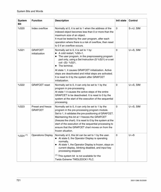
System Bits and Words
%S20 Index overflow Normally at 0, it is set to 1 when the address of the indexed object becomes less than 0 or more than the maximum size of an object.It must be tested by the user program, after each operation where there is a risk of overflow, then reset to 0 if an overflow occurs.
0 S->U, SIM
%S21 GRAFCET initialization
Normally set to 0, it is set to 1 by:A cold restart, %S0=1,The user program, in the preprocessing program part only, using a Set Instruction (S %S21) or a set coil -(S)- %S21,The terminal.
At state 1, it causes GRAFCET initialization. Active steps are deactivated and initial steps are activated. It is reset to 0 by the system after GRAFCET initialization.
0 U->S, SIM
%S22 GRAFCET reset Normally set to 0, it can only be set to 1 by the program in pre-processing.At state 1 it causes the active steps of the entire GRAFCET to be deactivated. It is reset to 0 by the system at the start of the execution of the sequential processing.
0 U->S, SIM
%S23 Preset and freeze GRAFCET
Normally set to 0, it can only be set to 1 by the program in the pre-processing program module.Set to 1, it validates the pre-positioning of GRAFCET. Maintaining this bit at 1 freezes the GRAFCET (freezes the chart). It is reset to 0 by the system at the start of the execution of the sequential processing to ensure that the GRAFCET chart moves on from the frozen situation.
0 U->S, SIM
%S24 (1) Operations Display Normally at 0, this bit can be set to 1 by the user.At state 0, the Operator Display is operating normally,At state 1, the Operator Display is frozen, stays on current display, blinking disabled, and input key processing stopped.
(1) This system bit is not available for the Twido Extreme TWDLEDCK1 PLC.
0 U->S
System Bit
Function Description Init state Control
721 35011386 05/2009
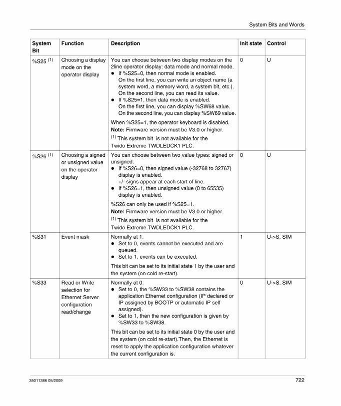
System Bits and Words
%S25 (1) Choosing a display mode on the operator display
You can choose between two display modes on the 2line operator display: data mode and normal mode.
If %S25=0, then normal mode is enabled. On the first line, you can write an object name (a system word, a memory word, a system bit, etc.).On the second line, you can read its value.If %S25=1, then data mode is enabled. On the first line, you can display %SW68 value.On the second line, you can display %SW69 value.
When %S25=1, the operator keyboard is disabled.Note: Firmware version must be V3.0 or higher.(1) This system bit is not available for the Twido Extreme TWDLEDCK1 PLC.
0 U
%S26 (1) Choosing a signed or unsigned value on the operator display
You can choose between two value types: signed or unsigned.
If %S26=0, then signed value (-32768 to 32767) display is enabled.+/- signs appear at each start of line.If %S26=1, then unsigned value (0 to 65535) display is enabled.
%S26 can only be used if %S25=1.Note: Firmware version must be V3.0 or higher.(1) This system bit is not available for the Twido Extreme TWDLEDCK1 PLC.
0 U
%S31 Event mask Normally at 1.Set to 0, events cannot be executed and are queued.Set to 1, events can be executed,
This bit can be set to its initial state 1 by the user and the system (on cold re-start).
1 U->S, SIM
%S33 Read or Write selection for Ethernet Server configuration read/change
Normally at 0.Set to 0, the %SW33 to %SW38 contains the application Ethernet configuration (IP declared or IP assigned by BOOTP or automatic IP self assigned).Set to 1, then the new configuration is given by %SW33 to %SW38.
This bit can be set to its initial state 0 by the user and the system (on cold re-start).Then, the Ethernet is reset to apply the application configuration whatever the current configuration is.
0 U->S, SIM
System Bit
Function Description Init state Control
35011386 05/2009 722
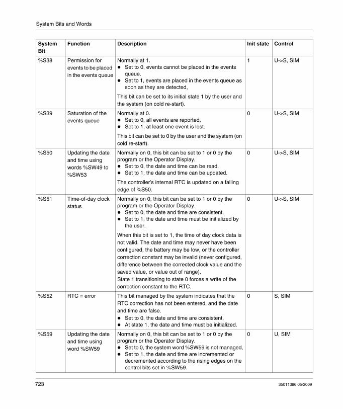
System Bits and Words
%S38 Permission for events to be placed in the events queue
Normally at 1.Set to 0, events cannot be placed in the events queue.Set to 1, events are placed in the events queue as soon as they are detected,
This bit can be set to its initial state 1 by the user and the system (on cold re-start).
1 U->S, SIM
%S39 Saturation of the events queue
Normally at 0.Set to 0, all events are reported,Set to 1, at least one event is lost.
This bit can be set to 0 by the user and the system (on cold re-start).
0 U->S, SIM
%S50 Updating the date and time using words %SW49 to %SW53
Normally on 0, this bit can be set to 1 or 0 by the program or the Operator Display.
Set to 0, the date and time can be read,Set to 1, the date and time can be updated.
The controller’s internal RTC is updated on a falling edge of %S50.
0 U->S, SIM
%S51 Time-of-day clock status
Normally on 0, this bit can be set to 1 or 0 by the program or the Operator Display.
Set to 0, the date and time are consistent,Set to 1, the date and time must be initialized by the user.
When this bit is set to 1, the time of day clock data is not valid. The date and time may never have been configured, the battery may be low, or the controller correction constant may be invalid (never configured, difference between the corrected clock value and the saved value, or value out of range). State 1 transitioning to state 0 forces a write of the correction constant to the RTC.
0 U->S, SIM
%S52 RTC = error This bit managed by the system indicates that the RTC correction has not been entered, and the date and time are false.
Set to 0, the date and time are consistent,At state 1, the date and time must be initialized.
0 S, SIM
%S59 Updating the date and time using word %SW59
Normally on 0, this bit can be set to 1 or 0 by the program or the Operator Display.
Set to 0, the system word %SW59 is not managed,Set to 1, the date and time are incremented or decremented according to the rising edges on the control bits set in %SW59.
0 U, SIM
System Bit
Function Description Init state Control
723 35011386 05/2009
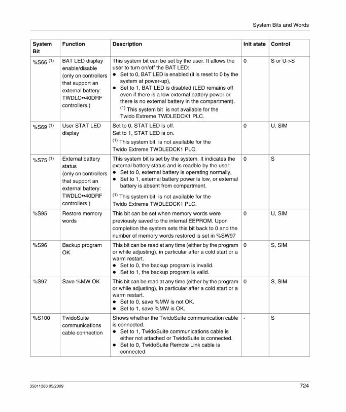
System Bits and Words
%S66 (1) BAT LED display enable/disable(only on controllers that support an external battery: TWDLC••40DRF controllers.)
This system bit can be set by the user. It allows the user to turn on/off the BAT LED:
Set to 0, BAT LED is enabled (it is reset to 0 by the system at power-up),Set to 1, BAT LED is disabled (LED remains off even if there is a low external battery power or there is no external battery in the compartment).(1) This system bit is not available for the Twido Extreme TWDLEDCK1 PLC.
0 S or U->S
%S69 (1) User STAT LED display
Set to 0, STAT LED is off.Set to 1, STAT LED is on.(1) This system bit is not available for the Twido Extreme TWDLEDCK1 PLC.
0 U, SIM
%S75 (1) External battery status(only on controllers that support an external battery: TWDLC••40DRF controllers.)
This system bit is set by the system. It indicates the external battery status and is readble by the user:
Set to 0, external battery is operating normally,Set to 1, external battery power is low, or external battery is absent from compartment.
(1) This system bit is not available for the Twido Extreme TWDLEDCK1 PLC.
0 S
%S95 Restore memory words
This bit can be set when memory words were previously saved to the internal EEPROM. Upon completion the system sets this bit back to 0 and the number of memory words restored is set in %SW97
0 U, SIM
%S96 Backup program OK
This bit can be read at any time (either by the program or while adjusting), in particular after a cold start or a warm restart.
Set to 0, the backup program is invalid.Set to 1, the backup program is valid.
0 S, SIM
%S97 Save %MW OK This bit can be read at any time (either by the program or while adjusting), in particular after a cold start or a warm restart.
Set to 0, save %MW is not OK.Set to 1, save %MW is OK.
0 S, SIM
%S100 TwidoSuite communications cable connection
Shows whether the TwidoSuite communication cable is connected.
Set to 1, TwidoSuite communications cable is either not attached or TwidoSuite is connected.Set to 0, TwidoSuite Remote Link cable is connected.
- S
System Bit
Function Description Init state Control
35011386 05/2009 724
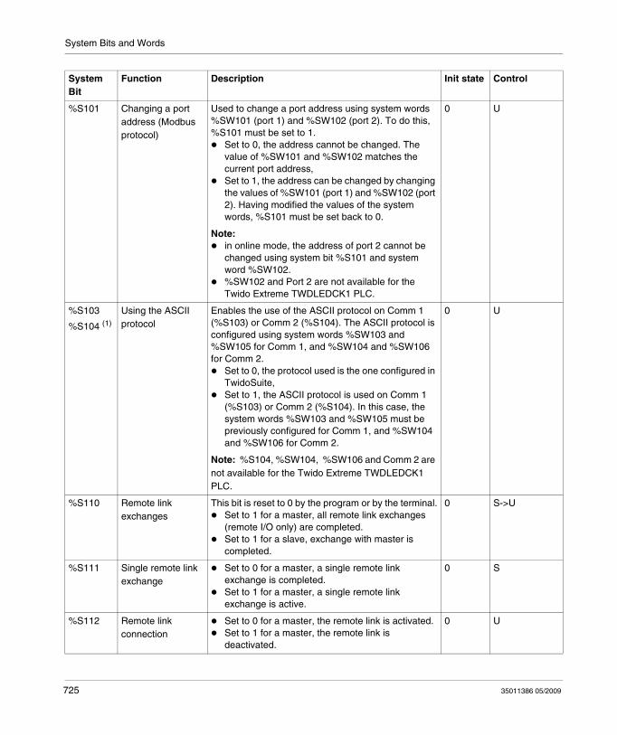
System Bits and Words
%S101 Changing a port address (Modbus protocol)
Used to change a port address using system words %SW101 (port 1) and %SW102 (port 2). To do this, %S101 must be set to 1.
Set to 0, the address cannot be changed. The value of %SW101 and %SW102 matches the current port address,Set to 1, the address can be changed by changing the values of %SW101 (port 1) and %SW102 (port 2). Having modified the values of the system words, %S101 must be set back to 0.
Note:in online mode, the address of port 2 cannot be changed using system bit %S101 and system word %SW102.%SW102 and Port 2 are not available for the Twido Extreme TWDLEDCK1 PLC.
0 U
%S103
%S104 (1)
Using the ASCII protocol
Enables the use of the ASCII protocol on Comm 1 (%S103) or Comm 2 (%S104). The ASCII protocol is configured using system words %SW103 and %SW105 for Comm 1, and %SW104 and %SW106 for Comm 2.
Set to 0, the protocol used is the one configured in TwidoSuite,Set to 1, the ASCII protocol is used on Comm 1 (%S103) or Comm 2 (%S104). In this case, the system words %SW103 and %SW105 must be previously configured for Comm 1, and %SW104 and %SW106 for Comm 2.
Note: %S104, %SW104, %SW106 and Comm 2 are not available for the Twido Extreme TWDLEDCK1 PLC.
0 U
%S110 Remote link exchanges
This bit is reset to 0 by the program or by the terminal.Set to 1 for a master, all remote link exchanges (remote I/O only) are completed.Set to 1 for a slave, exchange with master is completed.
0 S->U
%S111 Single remote link exchange
Set to 0 for a master, a single remote link exchange is completed.Set to 1 for a master, a single remote link exchange is active.
0 S
%S112 Remote link connection
Set to 0 for a master, the remote link is activated.Set to 1 for a master, the remote link is deactivated.
0 U
System Bit
Function Description Init state Control
725 35011386 05/2009
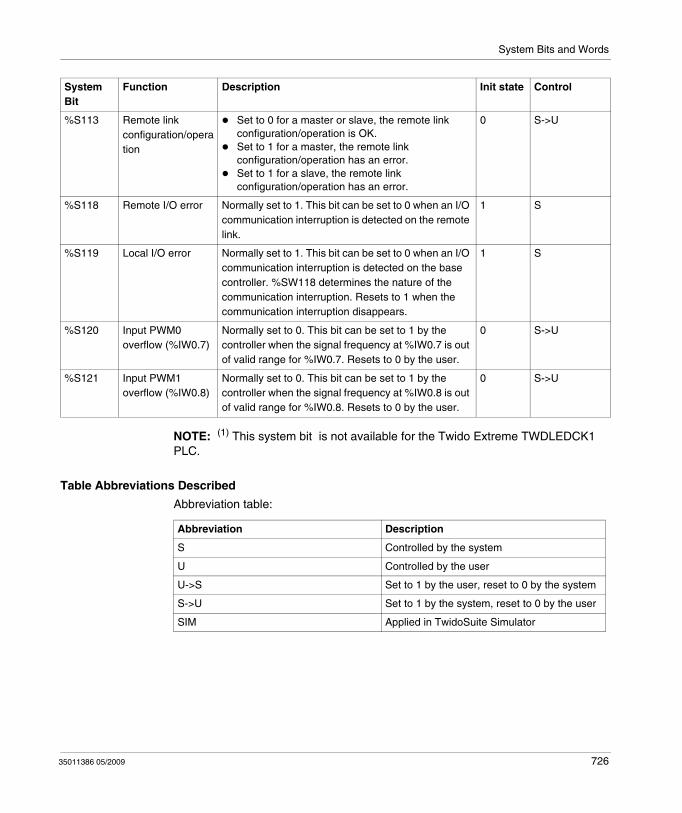
System Bits and Words
NOTE: (1) This system bit is not available for the Twido Extreme TWDLEDCK1 PLC.
Table Abbreviations Described
Abbreviation table:
%S113 Remote link configuration/operation
Set to 0 for a master or slave, the remote link configuration/operation is OK.Set to 1 for a master, the remote link configuration/operation has an error.Set to 1 for a slave, the remote link configuration/operation has an error.
0 S->U
%S118 Remote I/O error Normally set to 1. This bit can be set to 0 when an I/O communication interruption is detected on the remote link.
1 S
%S119 Local I/O error Normally set to 1. This bit can be set to 0 when an I/O communication interruption is detected on the base controller. %SW118 determines the nature of the communication interruption. Resets to 1 when the communication interruption disappears.
1 S
%S120 Input PWM0 overflow (%IW0.7)
Normally set to 0. This bit can be set to 1 by the controller when the signal frequency at %IW0.7 is out of valid range for %IW0.7. Resets to 0 by the user.
0 S->U
%S121 Input PWM1 overflow (%IW0.8)
Normally set to 0. This bit can be set to 1 by the controller when the signal frequency at %IW0.8 is out of valid range for %IW0.8. Resets to 0 by the user.
0 S->U
System Bit
Function Description Init state Control
Abbreviation Description
S Controlled by the system
U Controlled by the user
U->S Set to 1 by the user, reset to 0 by the system
S->U Set to 1 by the system, reset to 0 by the user
SIM Applied in TwidoSuite Simulator
35011386 05/2009 726
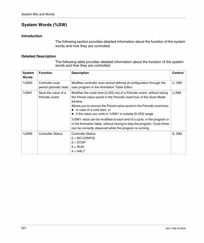
System Bits and Words
System Words (%SW)
Introduction
The following section provides detailed information about the function of the system words and how they are controlled.
Detailed Description
The following table provides detailed information about the function of the system words and how they are controlled:
System Words
Function Description Control
%SW0 Controller scan period (periodic task)
Modifies controller scan period defined at configuration through the user program in the Animation Table Editor.
U, SIM
%SW1 Save the value of a Periodic event
Modifies the cycle time [5-255 ms] of a Periodic event, without losing the Period value saved in the Periodic event box of the Scan Mode window. Allows you to recover the Period value saved in the Periodic event box:
in case of a cold start, orif the value you write in %SW1 is outside [5-255] range.
%SW1 value can be modified at each end of a cycle, in the program or in the Animation table, without having to stop the program. Cycle times can be correctly observed while the program is running.
U,SIM
%SW6 Controller Status Controller Status:0 = NO CONFIG2 = STOP3 = RUN4 = HALT
S, SIM
727 35011386 05/2009
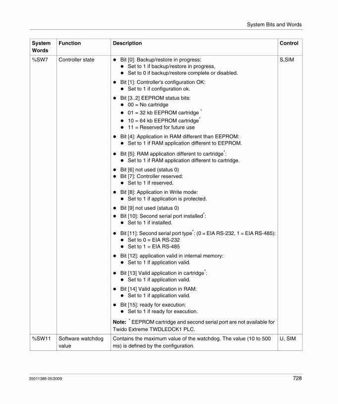
System Bits and Words
%SW7 Controller state Bit [0]: Backup/restore in progress:Set to 1 if backup/restore in progress,Set to 0 if backup/restore complete or disabled.
Bit [1]: Controller's configuration OK:Set to 1 if configuration ok.
Bit [3..2] EEPROM status bits:00 = No cartridge
01 = 32 kb EEPROM cartridge *
10 = 64 kb EEPROM cartridge*
11 = Reserved for future use
Bit [4]: Application in RAM different than EEPROM:Set to 1 if RAM application different to EEPROM.
Bit [5]: RAM application different to cartridge*:Set to 1 if RAM application different to cartridge.
Bit [6] not used (status 0)Bit [7]: Controller reserved:
Set to 1 if reserved.
Bit [8]: Application in Write mode:Set to 1 if application is protected.
Bit [9] not used (status 0)
Bit [10]: Second serial port installed*:Set to 1 if installed.
Bit [11]: Second serial port type*: (0 = EIA RS-232, 1 = EIA RS-485):Set to 0 = EIA RS-232Set to 1 = EIA RS-485
Bit [12]: application valid in internal memory:Set to 1 if application valid.
Bit [13] Valid application in cartridge*:Set to 1 if application valid.
Bit [14] Valid application in RAM:Set to 1 if application valid.
Bit [15]: ready for execution:Set to 1 if ready for execution.
Note: * EEPROM cartridge and second serial port are not available for Twido Extreme TWDLEDCK1 PLC.
S,SIM
%SW11 Software watchdog value
Contains the maximum value of the watchdog. The value (10 to 500 ms) is defined by the configuration.
U, SIM
System Words
Function Description Control
35011386 05/2009 728
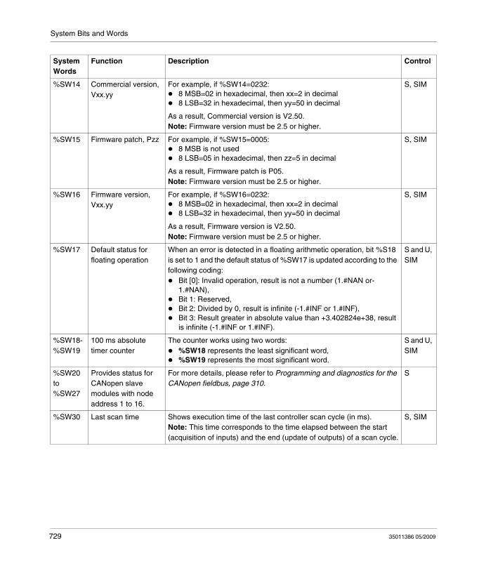
System Bits and Words
%SW14 Commercial version, Vxx.yy
For example, if %SW14=0232:8 MSB=02 in hexadecimal, then xx=2 in decimal8 LSB=32 in hexadecimal, then yy=50 in decimal
As a result, Commercial version is V2.50.Note: Firmware version must be 2.5 or higher.
S, SIM
%SW15 Firmware patch, Pzz For example, if %SW15=0005:8 MSB is not used8 LSB=05 in hexadecimal, then zz=5 in decimal
As a result, Firmware patch is P05.Note: Firmware version must be 2.5 or higher.
S, SIM
%SW16 Firmware version, Vxx.yy
For example, if %SW16=0232:8 MSB=02 in hexadecimal, then xx=2 in decimal8 LSB=32 in hexadecimal, then yy=50 in decimal
As a result, Firmware version is V2.50.Note: Firmware version must be 2.5 or higher.
S, SIM
%SW17 Default status for floating operation
When an error is detected in a floating arithmetic operation, bit %S18 is set to 1 and the default status of %SW17 is updated according to the following coding:
Bit [0]: Invalid operation, result is not a number (1.#NAN or-1.#NAN),Bit 1: Reserved,Bit 2: Divided by 0, result is infinite (-1.#INF or 1.#INF),Bit 3: Result greater in absolute value than +3.402824e+38, result is infinite (-1.#INF or 1.#INF).
S and U, SIM
%SW18-%SW19
100 ms absolute timer counter
The counter works using two words:%SW18 represents the least significant word,%SW19 represents the most significant word.
S and U, SIM
%SW20 to %SW27
Provides status for CANopen slave modules with node address 1 to 16.
For more details, please refer to Programming and diagnostics for the CANopen fieldbus, page 310.
S
%SW30 Last scan time Shows execution time of the last controller scan cycle (in ms).Note: This time corresponds to the time elapsed between the start (acquisition of inputs) and the end (update of outputs) of a scan cycle.
S, SIM
System Words
Function Description Control
729 35011386 05/2009
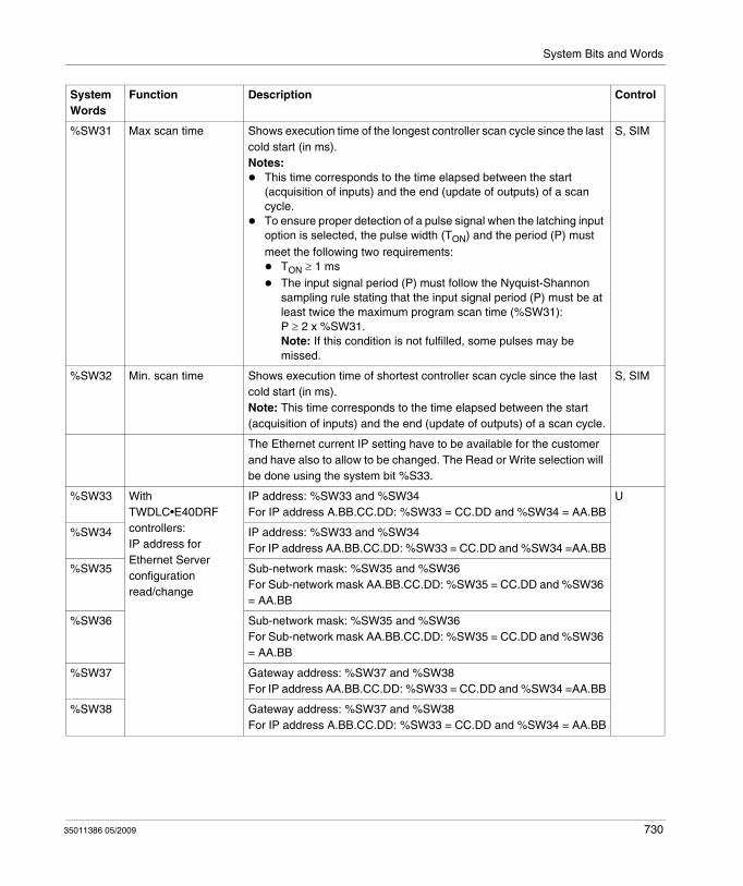
System Bits and Words
%SW31 Max scan time Shows execution time of the longest controller scan cycle since the last cold start (in ms).Notes:
This time corresponds to the time elapsed between the start (acquisition of inputs) and the end (update of outputs) of a scan cycle.To ensure proper detection of a pulse signal when the latching input option is selected, the pulse width (TON) and the period (P) must meet the following two requirements:
TON ≥ 1 msThe input signal period (P) must follow the Nyquist-Shannon sampling rule stating that the input signal period (P) must be at least twice the maximum program scan time (%SW31): P ≥ 2 x %SW31.Note: If this condition is not fulfilled, some pulses may be missed.
S, SIM
%SW32 Min. scan time Shows execution time of shortest controller scan cycle since the last cold start (in ms).Note: This time corresponds to the time elapsed between the start (acquisition of inputs) and the end (update of outputs) of a scan cycle.
S, SIM
The Ethernet current IP setting have to be available for the customer and have also to allow to be changed. The Read or Write selection will be done using the system bit %S33.
%SW33 With TWDLC•E40DRF controllers:IP address for Ethernet Server configuration read/change
IP address: %SW33 and %SW34For IP address A.BB.CC.DD: %SW33 = CC.DD and %SW34 = AA.BB
U
%SW34 IP address: %SW33 and %SW34For IP address AA.BB.CC.DD: %SW33 = CC.DD and %SW34 =AA.BB
%SW35 Sub-network mask: %SW35 and %SW36For Sub-network mask AA.BB.CC.DD: %SW35 = CC.DD and %SW36 = AA.BB
%SW36 Sub-network mask: %SW35 and %SW36For Sub-network mask AA.BB.CC.DD: %SW35 = CC.DD and %SW36 = AA.BB
%SW37 Gateway address: %SW37 and %SW38For IP address AA.BB.CC.DD: %SW33 = CC.DD and %SW34 =AA.BB
%SW38 Gateway address: %SW37 and %SW38For IP address A.BB.CC.DD: %SW33 = CC.DD and %SW34 = AA.BB
System Words
Function Description Control
35011386 05/2009 730
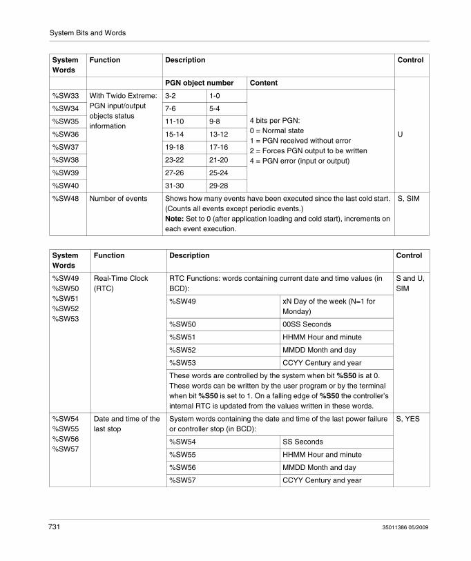
System Bits and Words
PGN object number Content
U
%SW33 With Twido Extreme:PGN input/output objects status information
3-2 1-0
4 bits per PGN:0 = Normal state1 = PGN received without error2 = Forces PGN output to be written4 = PGN error (input or output)
%SW34 7-6 5-4
%SW35 11-10 9-8
%SW36 15-14 13-12
%SW37 19-18 17-16
%SW38 23-22 21-20
%SW39 27-26 25-24
%SW40 31-30 29-28
%SW48 Number of events Shows how many events have been executed since the last cold start. (Counts all events except periodic events.)Note: Set to 0 (after application loading and cold start), increments on each event execution.
S, SIM
System Words
Function Description Control
System Words
Function Description Control
%SW49%SW50%SW51%SW52%SW53
Real-Time Clock (RTC)
RTC Functions: words containing current date and time values (in BCD):
S and U, SIM
%SW49 xN Day of the week (N=1 for Monday)
%SW50 00SS Seconds
%SW51 HHMM Hour and minute
%SW52 MMDD Month and day
%SW53 CCYY Century and year
These words are controlled by the system when bit %S50 is at 0. These words can be written by the user program or by the terminal when bit %S50 is set to 1. On a falling edge of %S50 the controller’s internal RTC is updated from the values written in these words.
%SW54%SW55%SW56%SW57
Date and time of the last stop
System words containing the date and time of the last power failure or controller stop (in BCD):
S, YES
%SW54 SS Seconds
%SW55 HHMM Hour and minute
%SW56 MMDD Month and day
%SW57 CCYY Century and year
731 35011386 05/2009
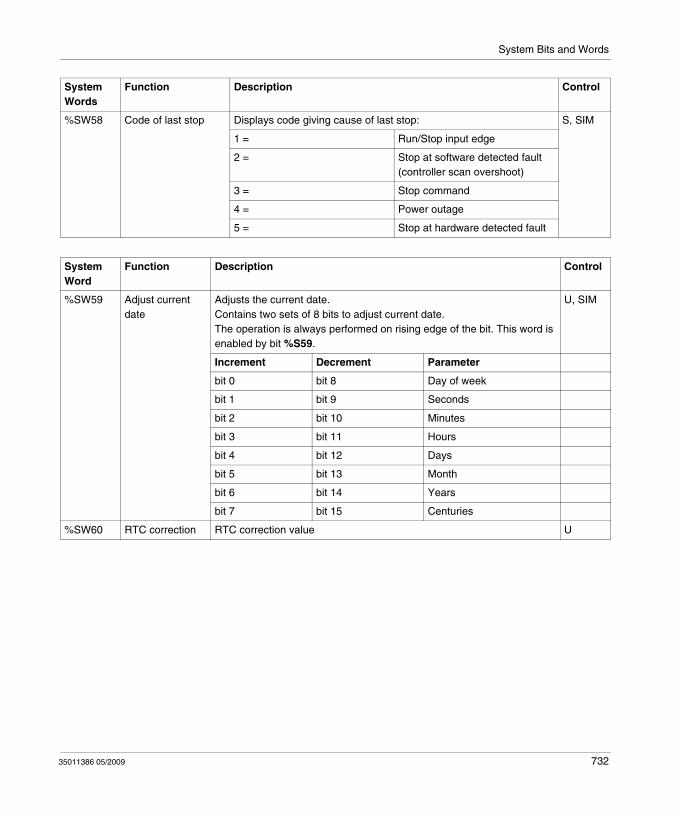
System Bits and Words
%SW58 Code of last stop Displays code giving cause of last stop: S, SIM
1 = Run/Stop input edge
2 = Stop at software detected fault (controller scan overshoot)
3 = Stop command
4 = Power outage
5 = Stop at hardware detected fault
System Words
Function Description Control
System Word
Function Description Control
%SW59 Adjust current date
Adjusts the current date.Contains two sets of 8 bits to adjust current date.The operation is always performed on rising edge of the bit. This word is enabled by bit %S59.
U, SIM
Increment Decrement Parameter
bit 0 bit 8 Day of week
bit 1 bit 9 Seconds
bit 2 bit 10 Minutes
bit 3 bit 11 Hours
bit 4 bit 12 Days
bit 5 bit 13 Month
bit 6 bit 14 Years
bit 7 bit 15 Centuries
%SW60 RTC correction RTC correction value U
35011386 05/2009 732
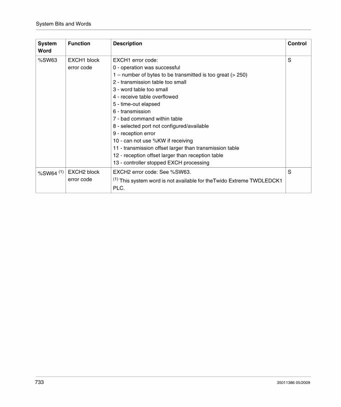
System Bits and Words
%SW63 EXCH1 block error code
EXCH1 error code:0 - operation was successful1 – number of bytes to be transmitted is too great (> 250)2 - transmission table too small3 - word table too small4 - receive table overflowed5 - time-out elapsed6 - transmission7 - bad command within table8 - selected port not configured/available9 - reception error10 - can not use %KW if receiving11 - transmission offset larger than transmission table12 - reception offset larger than reception table13 - controller stopped EXCH processing
S
%SW64 (1) EXCH2 block error code
EXCH2 error code: See %SW63.(1) This system word is not available for theTwido Extreme TWDLEDCK1 PLC.
S
System Word
Function Description Control
733 35011386 05/2009
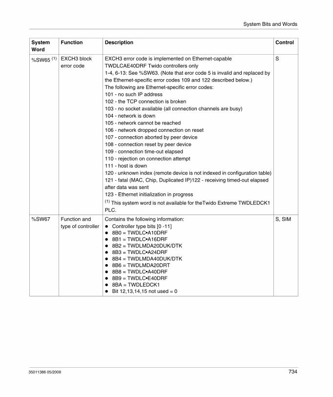
System Bits and Words
%SW65 (1) EXCH3 block error code
EXCH3 error code is implemented on Ethernet-capable TWDLCAE40DRF Twido controllers only1-4, 6-13: See %SW63. (Note that eror code 5 is invalid and replaced by the Ethernet-specific error codes 109 and 122 described below.)The following are Ethernet-specific error codes:101 - no such IP address102 - the TCP connection is broken103 - no socket available (all connection channels are busy)104 - network is down105 - network cannot be reached106 - network dropped connection on reset107 - connection aborted by peer device108 - connection reset by peer device109 - connection time-out elapsed110 - rejection on connection attempt111 - host is down120 - unknown index (remote device is not indexed in configuration table)121 - fatal (MAC, Chip, Duplicated IP)122 - receiving timed-out elapsed after data was sent123 - Ethernet initialization in progress(1) This system word is not available for theTwido Extreme TWDLEDCK1 PLC.
S
%SW67 Function and type of controller
Contains the following information:Controller type bits [0 -11]8B0 = TWDLC•A10DRF8B1 = TWDLC•A16DRF8B2 = TWDLMDA20DUK/DTK8B3 = TWDLC•A24DRF8B4 = TWDLMDA40DUK/DTK8B6 = TWDLMDA20DRT8B8 = TWDLC•A40DRF8B9 = TWDLC•E40DRF8BA = TWDLEDCK1Bit 12,13,14,15 not used = 0
S, SIM
System Word
Function Description Control
35011386 05/2009 734
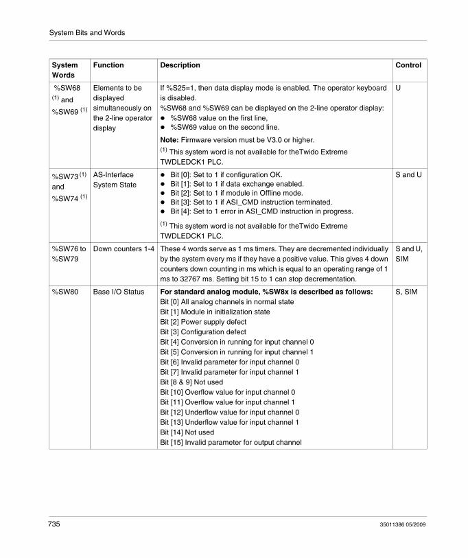
System Bits and Words
System Words
Function Description Control
%SW68 (1) and
%SW69 (1)
Elements to be displayed simultaneously on the 2-line operator display
If %S25=1, then data display mode is enabled. The operator keyboard is disabled. %SW68 and %SW69 can be displayed on the 2-line operator display:
%SW68 value on the first line,%SW69 value on the second line.
Note: Firmware version must be V3.0 or higher.(1) This system word is not available for theTwido Extreme TWDLEDCK1 PLC.
U
%SW73 (1) and
%SW74 (1)
AS-Interface System State
Bit [0]: Set to 1 if configuration OK.Bit [1]: Set to 1 if data exchange enabled. Bit [2]: Set to 1 if module in Offline mode.Bit [3]: Set to 1 if ASI_CMD instruction terminated. Bit [4]: Set to 1 error in ASI_CMD instruction in progress.
(1) This system word is not available for theTwido Extreme TWDLEDCK1 PLC.
S and U
%SW76 to %SW79
Down counters 1-4 These 4 words serve as 1 ms timers. They are decremented individually by the system every ms if they have a positive value. This gives 4 down counters down counting in ms which is equal to an operating range of 1 ms to 32767 ms. Setting bit 15 to 1 can stop decrementation.
S and U, SIM
%SW80 Base I/O Status For standard analog module, %SW8x is described as follows:Bit [0] All analog channels in normal stateBit [1] Module in initialization stateBit [2] Power supply defectBit [3] Configuration defectBit [4] Conversion in running for input channel 0Bit [5] Conversion in running for input channel 1Bit [6] Invalid parameter for input channel 0Bit [7] Invalid parameter for input channel 1Bit [8 & 9] Not usedBit [10] Overflow value for input channel 0Bit [11] Overflow value for input channel 1Bit [12] Underflow value for input channel 0Bit [13] Underflow value for input channel 1Bit [14] Not usedBit [15] Invalid parameter for output channel
S, SIM
735 35011386 05/2009
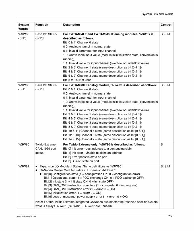
System Bits and Words
%SW80cont’d
Base I/O Statuscont’d
For TWDAMI4LT and TWDAMM6HT analog modules, %SW8x is described as follows:Bit [0 & 1] Channel 0 state0 0: Analog channel in normal state0 1: Invalid parameter for input channel1 0: Unavailable input value (module in initialization state, conversion in running),1 1: Invalid value for input channel (overflow or underflow value)Bit [2 & 3] Channel 1 state (same description as bit [0 & 1])Bit [4 & 5] Channel 2 state (same description as bit [0 & 1])Bit [6 & 7] Channel 3 state (same description as bit [0 & 1])Bit [8 to 15] Not used
S, SIM
%SW80cont’d
Base I/O Statuscont’d
For TWDAMI8HT analog module, %SW8x is described as follows:Bit [0 & 1] Channel 0 state0 0: Analog channel in normal state0 1: Invalid parameter for input channel1 0: Unavailable input value (module in initialization state, conversion in running),1 1: Invalid value for input channel (overflow or underflow value)Bit [2 & 3] Channel 1 state (same description as bit [0 & 1])Bit [4 & 5] Channel 2 state (same description as bit [0 & 1])Bit [6 & 7] Channel 3 state (same description as bit [0 & 1])Bit [8 & 9] Channel 4 state (same description as bit [0 & 1])Bit [10 & 11] Channel 5 state (same description as bit [0 & 1])Bit [12 & 13] Channel 6 state (same description as bit [0 & 1])Bit [14 & 15] Channel 7 state (same description as bit [0 & 1])
S, SIM
%SW80 Twido Extreme CANJ1939 port status
For Twido Extreme only, %SW80 is described as follows:Bit [0] Init error - Lost address to a contending claimBit [1] Init error - Unable to claim an addressBit [2] Error passive state on portBit [3] Bus-off state on port
S
%SW81 Expansion I/O Module 1 Status: Same definitions as %SW80CANopen Master Module Status at Expansion Address 1:
Bit [0] Configuration state (1 = configuration OK; 0 = configuration error)Bit [1] Operational state (1 = PDO exchange ON; 0 = PDO exchange OFF)Bit [2] Init state (1 = init state ON; 0 = init state OFF)Bit [3] CAN_CMD instruction complete (1 = complete; 0 = in progress)Bit [4] CAN_CMD instruction error (1 = error; 0 = OK)Bit [5] Initialization error (1 = error; 0 = OK)Bit [6] Loss of message, power supply error (1 = error; 0 = OK)
Note: For the Twido Extreme integrated CANopen bus master the reserved specific system word is always %SW81 (%SW82 ... %SW87 are unused).
S, SIM
System Words
Function Description Control
35011386 05/2009 736
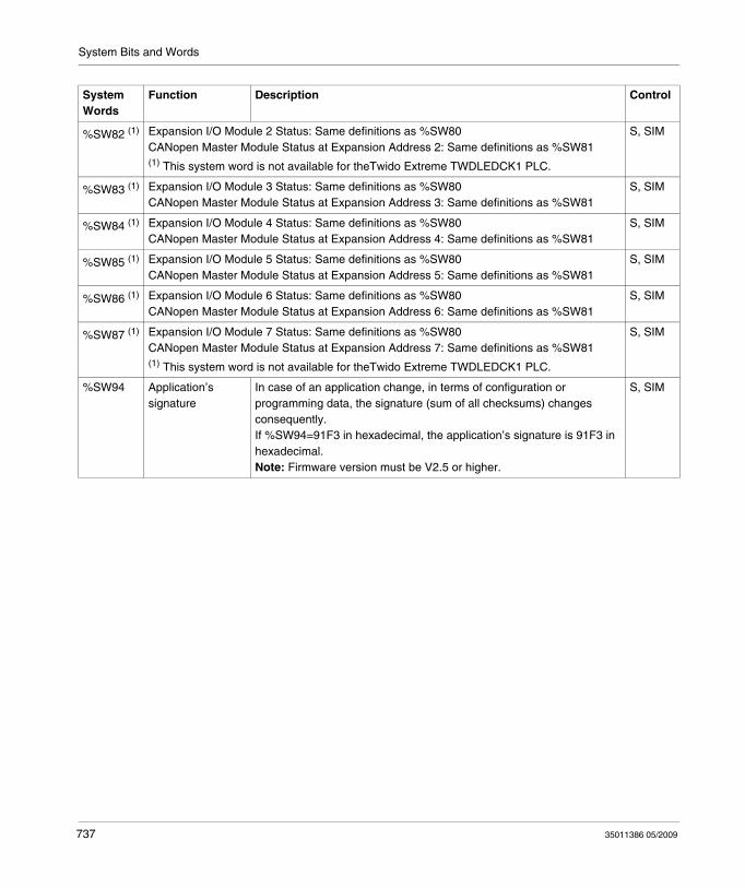
System Bits and Words
%SW82 (1) Expansion I/O Module 2 Status: Same definitions as %SW80CANopen Master Module Status at Expansion Address 2: Same definitions as %SW81(1) This system word is not available for theTwido Extreme TWDLEDCK1 PLC.
S, SIM
%SW83 (1) Expansion I/O Module 3 Status: Same definitions as %SW80CANopen Master Module Status at Expansion Address 3: Same definitions as %SW81
S, SIM
%SW84 (1) Expansion I/O Module 4 Status: Same definitions as %SW80CANopen Master Module Status at Expansion Address 4: Same definitions as %SW81
S, SIM
%SW85 (1) Expansion I/O Module 5 Status: Same definitions as %SW80CANopen Master Module Status at Expansion Address 5: Same definitions as %SW81
S, SIM
%SW86 (1) Expansion I/O Module 6 Status: Same definitions as %SW80CANopen Master Module Status at Expansion Address 6: Same definitions as %SW81
S, SIM
%SW87 (1) Expansion I/O Module 7 Status: Same definitions as %SW80CANopen Master Module Status at Expansion Address 7: Same definitions as %SW81(1) This system word is not available for theTwido Extreme TWDLEDCK1 PLC.
S, SIM
%SW94 Application’s signature
In case of an application change, in terms of configuration or programming data, the signature (sum of all checksums) changes consequently.If %SW94=91F3 in hexadecimal, the application’s signature is 91F3 in hexadecimal.Note: Firmware version must be V2.5 or higher.
S, SIM
System Words
Function Description Control
737 35011386 05/2009
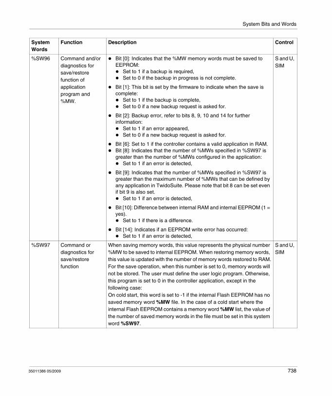
System Bits and Words
%SW96 Command and/or diagnostics for save/restore function of application program and %MW.
Bit [0]: Indicates that the %MW memory words must be saved to EEPROM:
Set to 1 if a backup is required,Set to 0 if the backup in progress is not complete.
Bit [1]: This bit is set by the firmware to indicate when the save is complete:
Set to 1 if the backup is complete,Set to 0 if a new backup request is asked for.
Bit [2]: Backup error, refer to bits 8, 9, 10 and 14 for further information:
Set to 1 if an error appeared,Set to 0 if a new backup request is asked for.
Bit [6]: Set to 1 if the controller contains a valid application in RAM.Bit [8]: Indicates that the number of %MWs specified in %SW97 is greater than the number of %MWs configured in the application:
Set to 1 if an error is detected,
Bit [9]: Indicates that the number of %MWs specified in %SW97 is greater than the maximum number of %MWs that can be defined by any application in TwidoSuite. Please note that bit 8 can be set even if bit 9 is also set.
Set to 1 if an error is detected,
Bit [10]: Difference between internal RAM and internal EEPROM (1 = yes).
Set to 1 if there is a difference.
Bit [14]: Indicates if an EEPROM write error has occurred:Set to 1 if an error is detected,
S and U, SIM
%SW97 Command or diagnostics for save/restore function
When saving memory words, this value represents the physical number %MW to be saved to internal EEPROM. When restoring memory words, this value is updated with the number of memory words restored to RAM.For the save operation, when this number is set to 0, memory words will not be stored. The user must define the user logic program. Otherwise, this program is set to 0 in the controller application, except in the following case:On cold start, this word is set to -1 if the internal Flash EEPROM has no saved memory word %MW file. In the case of a cold start where the internal Flash EEPROM contains a memory word %MW list, the value of the number of saved memory words in the file must be set in this system word %SW97.
S and U, SIM
System Words
Function Description Control
35011386 05/2009 738
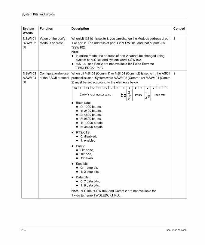
System Bits and Words
System Words
Function Description Control
%SW101%SW102 (1)
Value of the port’s Modbus address
When bit %S101 is set to 1, you can change the Modbus address of port 1 or port 2. The address of port 1 is %SW101, and that of port 2 is %SW102.Note:
in online mode, the address of port 2 cannot be changed using system bit %S101 and system word %SW102.%S102 and Port 2 are not available for Twido Extreme TWDLEDCK1 PLC.
S
%SW103%SW104 (1)
Configuration for use of the ASCII protocol
When bit %S103 (Comm 1) or %S104 (Comm 2) is set to 1, the ASCII protocol is used. System word %SW103 (Comm 1) or %SW104 (Comm 2) must be set according to the elements below:
Baud rate:0: 1200 bauds,1: 2400 bauds,2: 4800 bauds,3: 9600 bauds,4: 19200 bauds,5: 38400 bauds.
RTS/CTS: 0: disabled,1: enabled.
Parity: 00: none,10: odd,11: even.
Stop bit: 0: 1 stop bit,1: 2 stop bits.
Data bits: 0: 7 data bits,1: 8 data bits.
Note: %S104, %SW104 and Comm 2 are not available for Twido Extreme TWDLEDCK1 PLC.
S
739 35011386 05/2009
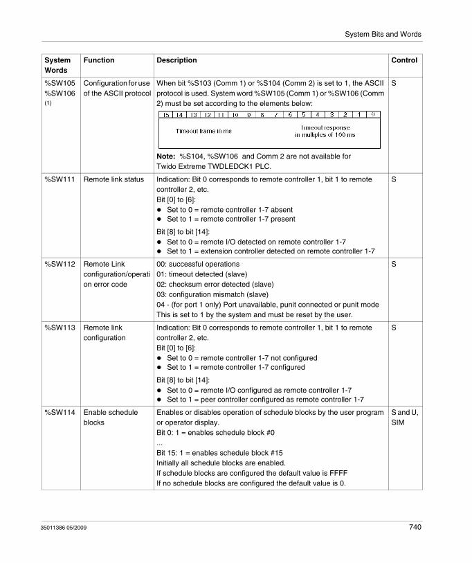
System Bits and Words
%SW105%SW106 (1)
Configuration for use of the ASCII protocol
When bit %S103 (Comm 1) or %S104 (Comm 2) is set to 1, the ASCII protocol is used. System word %SW105 (Comm 1) or %SW106 (Comm 2) must be set according to the elements below:
Note: %S104, %SW106 and Comm 2 are not available for Twido Extreme TWDLEDCK1 PLC.
S
%SW111 Remote link status Indication: Bit 0 corresponds to remote controller 1, bit 1 to remote controller 2, etc.Bit [0] to [6]:
Set to 0 = remote controller 1-7 absentSet to 1 = remote controller 1-7 present
Bit [8] to bit [14]:Set to 0 = remote I/O detected on remote controller 1-7Set to 1 = extension controller detected on remote controller 1-7
S
%SW112 Remote Link configuration/operation error code
00: successful operations01: timeout detected (slave)02: checksum error detected (slave)03: configuration mismatch (slave)04 - (for port 1 only) Port unavailable, punit connected or punit modeThis is set to 1 by the system and must be reset by the user.
S
%SW113 Remote link configuration
Indication: Bit 0 corresponds to remote controller 1, bit 1 to remote controller 2, etc.Bit [0] to [6]:
Set to 0 = remote controller 1-7 not configuredSet to 1 = remote controller 1-7 configured
Bit [8] to bit [14]:Set to 0 = remote I/O configured as remote controller 1-7Set to 1 = peer controller configured as remote controller 1-7
S
%SW114 Enable schedule blocks
Enables or disables operation of schedule blocks by the user program or operator display.Bit 0: 1 = enables schedule block #0... Bit 15: 1 = enables schedule block #15Initially all schedule blocks are enabled.If schedule blocks are configured the default value is FFFFIf no schedule blocks are configured the default value is 0.
S and U, SIM
System Words
Function Description Control
35011386 05/2009 740
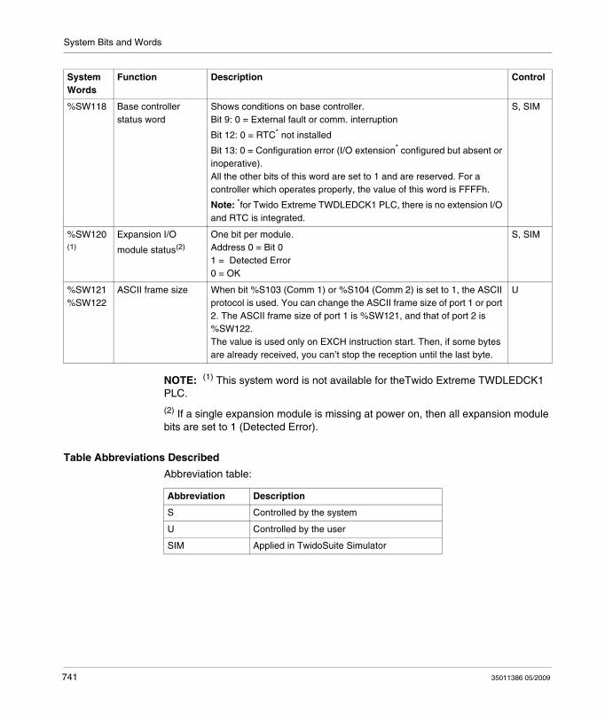
System Bits and Words
NOTE: (1) This system word is not available for theTwido Extreme TWDLEDCK1 PLC.
(2) If a single expansion module is missing at power on, then all expansion module bits are set to 1 (Detected Error).
Table Abbreviations Described
Abbreviation table:
%SW118 Base controller status word
Shows conditions on base controller.Bit 9: 0 = External fault or comm. interruption
Bit 12: 0 = RTC* not installed
Bit 13: 0 = Configuration error (I/O extension* configured but absent or inoperative).All the other bits of this word are set to 1 and are reserved. For a controller which operates properly, the value of this word is FFFFh.
Note: *for Twido Extreme TWDLEDCK1 PLC, there is no extension I/O and RTC is integrated.
S, SIM
%SW120 (1)
Expansion I/O
module status(2)
One bit per module.Address 0 = Bit 01 = Detected Error0 = OK
S, SIM
%SW121%SW122
ASCII frame size When bit %S103 (Comm 1) or %S104 (Comm 2) is set to 1, the ASCII protocol is used. You can change the ASCII frame size of port 1 or port 2. The ASCII frame size of port 1 is %SW121, and that of port 2 is %SW122.The value is used only on EXCH instruction start. Then, if some bytes are already received, you can’t stop the reception until the last byte.
U
System Words
Function Description Control
Abbreviation Description
S Controlled by the system
U Controlled by the user
SIM Applied in TwidoSuite Simulator
741 35011386 05/2009
Glossary
35011386 05/2009
Glossary
0-9
%Prefix that identifies internal memory addresses in the controller that are used to store the value of program variables, constants, I/O, and so on.
A
AddressesInternal registers in the controller used to store values for program variables, constants, I/O, and so on. Addresses are identified with a percentage symbol (%) prefix. For example, %I0.1 specifies an address within the controller RAM memory containing the value for input channel 1.
Analog potentiometerAn applied voltage that can be adjusted and converted into a discrete value for use by an application.
Analyze programA command that compiles a program and checks for program errors: syntax and structure errors, symbols without corresponding addresses, resources used by the program that are not available, and if the program does not fit in available controller memory. Error Messages are displayed in the Program Errors Viewer.
35011386 05/2009 742
Glossary
Animation tableTable created within a language editor or an operating screen. When a PC is connected to the controller, provides a view of controller variables and allows values to be forced when debugging. Can be saved as a separate file with an extension of .tat.
Animation Tables EditorA specialized window in the TwidoSuite application for viewing and creating Animation Tables.
ApplicationA TwidoSuite application consists of a program, configuration data, symbols, and documentation.
Application browserA specialized window in the TwidoSuite that displays a graphical tree-like view of an application. Provides for convenient configuration and viewing of an application.
Application fileTwido applications are stored as file type .twd.
ASCII(American Standard Code for Information Interchange) Communication protocol for representing alphanumeric characters, notably letters, figures and certain graphic and control characters.
Auto line validateWhen inserting or modifying List instructions, this optional setting allows for program lines to be validated as each is entered for errors and unresolved symbols. Each element must be corrected before you can exit the line. Selected using the Preferences dialog box.
Auto loadA feature that is enabled and provides for the automatic transfer of an application from a backup cartridge to the controller RAM in case of a lost or corrupted application. At power up, the controller compares the application that is presently in the controller RAM to the application in the optional backup memory cartridge (if installed). If there is a difference, then the copy in the backup cartridge is copied to the controller and the internal EEPROM. If the backup cartridge is not installed, then the application in the internal EEPROM is copied to the controller.
743 35011386 05/2009
Glossary
B
BackupA command that copies the application in controller RAM into both the controller internal EEPROM and the optional backup memory cartridge (if installed).
BootPA UDP/IP-based protocol (Bootstrap Protocol) which allows a booting host to configure itself dynamically and without user supervision. BootP provides a means to notify a host of its assigned IP address.
C
CANController Area Network: field bus originally developed for automobile applications which is now used in many sectors, from industrial to tertiary.
CiACAN in Automation: international organization of users and manufacturers of CAN products.
ClientA computer process requesting service from other computer processes.
COBCommunication OBject: transport unit on CAN bus. A COB is identified by a unique identifier, which is coded on 11 bits, [0, 2047]. A COB contains a maximum of 8 data bytes. The priority of a COB transmission is shown by its identifier - the weaker the identifier, the more priority the associated COB has.
CoilA ladder diagram element representing an output from the controller.
35011386 05/2009 744
Glossary
Cold start or restartA start up by the controller with all data initialized to default values, and the program started from the beginning with all variables cleared. All software and hardware settings are initialized. A cold restart can be caused by loading a new application into controller RAM. Any controller without battery backup powers up in Cold Start.
Comment linesIn List programs, comments can be entered on separate lines from instructions. Comments lines do not have line numbers, and must be inserted within parenthesis and asterisks such as: (*COMMENTS GO HERE*).
CommentsComments are texts you enter to document the purpose of a program. For Ladder programs, enter up to three lines of text in the Rung Header to describe the purpose of the rung. Each line can consist of 1 to 64 characters. For List programs, enter text on n unnumbered program line. Comments must be inserted within parenthesis and asterisks such as: (*COMMENTS GO HERE*).
Compact controllerType of Twido controller that provides a simple, all-in-one configuration with limited expansion. Modular is the other type of Twido controller.
Configuration editorSpecialized TwidoSuite window used to manage hardware and software configuration.
ConstantsA configured value that cannot be modified by the program being executed.
ContactA ladder diagram element representing an input to the controller.
CounterA function block used to count events (up or down counting).
Cross referencesGeneration of a list of operands, symbols, line/rung numbers, and operators used in an application to simplify creating and managing applications.
745 35011386 05/2009
Glossary
Cross References ViewerA specialized window in the TwidoSuite application for viewing cross references.
D
Data variableSee Variable.
Date/Clock functionsAllow control of events by month, day of month, and time of day. See Schedule Blocks.
Default gatewayThe IP address of the network or host to which all packets addressed to an unknown network or host are sent. The default gateway is typically a router or other device.
Drum controllerA function block that operates similar to an electromechanical drum controller with step changes associated with external events.
E
EDSElectronic Data Sheet: description file for each CAN device (provided by the manufacturers).
EEPROMElectrically Erasable Programmable Read-Only Memory. Twido has an internal EEPROM and an optional external EEPROM memory cartridge.
EraseThis command deletes the application in the controller, and has two options:
To delete the contents of the controller RAM, the controller internal EEPROM, and the installed optional backup cartridge.To delete the contents of the installed optional backup cartridge only.
35011386 05/2009 746
Glossary
Executive loaderA 32-Bit Windows application used for downloading a new Firmware Executive program to a Twido controller.
Expansion busExpansion I/O Modules connect to the base controller using this bus.
Expansion I/O modulesOptional Expansion I/O Modules are available to add I/O points to a Twido controller. (Not all controller models allow expansion).
F
Fast countersA function block that provides for faster up/down counting than available with the Counters function block. A Fast Counter can count up to a rate of 5 KHz.
FIFOFirst In, First Out. A function block used for queue operations.
Firmware executiveThe Firmware Executive is the operating system that executes your applications and manages controller operation.
ForcingIntentionally setting controller inputs and outputs to 0 or 1 values even if the actual values are different. Used for debugging while animating a program.
FrameA group of bits which form a discrete block of information. Frames contain network control information or data. The size and composition of a frame is determined by the network technology being used.
Framing typesTwo common framing types are Ethernet II and IEEE 802.3.
747 35011386 05/2009
Glossary
Function blockA program unit of inputs and variables organized to calculate values for outputs based on a defined function such as a timer or a counter.
G
GatewayA device which connects networks with dissimilar network architectures and which operates at the Application Layer. This term may refer to a router.
GrafcetGrafcet is used to represent the functioning of a sequential operation in a structured and graphic form.
This is an analytical method that divides any sequential control system into a series of steps, with which actions, transitions, and conditions are associated.
H
HostA node on a network.
HubA device which connects a series of flexible and centralized modules to create a network.
I
Init stateThe operating state of TwidoSuite that is displayed on the Status Bar when TwidoSuite is started or does not have an open application.
InitializeA command that sets all data values to initial states. The controller must be in Stop or Error mode.
35011386 05/2009 748
Glossary
InstanceA unique object in a program that belongs to a specific type of function block. For example, in the timer format %TMi, i is a number representing the instance.
Instruction List languageA program written in instruction list language (IL) is composed of a series of instructions executed sequentially by the controller. Each instruction is composed of a line number, an instruction code, and an operand.
InternetThe global interconnection of TCP/IP based computer communication networks.
IPInternet Protocol. A common network layer protocol. IP is most often used with TCP.
IP AddressInternet Protocol Address. A 32-bit address assigned to hosts using TCP/IP.
L
Ladder editorSpecialized TwidoSuite window used to edit a Ladder program.
Ladder languageA program written in Ladder language is composed of graphical representation of instructions of a controller program with symbols for contacts, coils, and blocks in a series of rungs executed sequentially by a controller.
Ladder list rungDisplays parts of a List program that are not reversible to Ladder language.
Latching inputIncoming pulses are captured and recorded for later examination by the application.
LIFOLast In, First Out. A function block used for stack operations.
749 35011386 05/2009
Glossary
List editorSimple program editor used to create and edit a List program.
M
MAC AddressMedia Access Control address. The hardware address of a device. A MAC address is assigned to an Ethernet TCP/IP module in the factory.
Master controllerA Twido controller configured to be the Master on a Remote Link network.
MBAPModbus Application Protocol
Memory cartridgeOptional Backup Memory Cartridges that can be used to backup and restore an application (program and configuration data). There are two sizes available: 32 and 64 Kb.
Memory usage indicatorA portion of the Status Bar in the TwidoSuite main window that displays a percentage of total controller memory used by an application. Provides an indication when memory is low.
ModbusA master-slave communications protocol that allows one single master to request responses from slaves.
Modular controllerType of Twido controller that offers flexible configuration with expansion capabilities. Compact is the other type of Twido controller.
Monitor stateThe operating state of TwidoSuite that is displayed on the Status Bar when a PC is connected to a controller in a non-write mode.
35011386 05/2009 750
Glossary
N
NetworkInterconnected devices sharing a common data path and protocol for communication.
NodeAn addressable device on a communications network.
O
Offline operationAn operation mode of TwidoSuite when a PC is not connected to the controller and the application in PC memory is not the same as the application in controller memory. You create and develop an application in Offline operation.
Offline stateThe operating state of TwidoSuite that is displayed on the Status Bar when a PC is not connected to a controller.
Online operationAn operation mode of TwidoSuite when a PC is connected to the controller and the application in PC memory is the same as the application in controller memory. Online operation can be used to debug an application.
Online stateThe operating state of TwidoSuite that is displayed on the Status Bar when a PC is connected to the controller.
OperandA number, address, or symbol representing a value that a program can manipulate in an instruction.
Operating statesIndicates the TwidoSuite state. Displayed in the status bar. There are four operating states: Initial, Offline, Online, and Monitor.
751 35011386 05/2009
Glossary
OperatorA symbol or code specifying the operation to be performed by an instruction.
P
PacketThe unit of data sent across a network.
PCPersonal Computer.
Peer controllerA Twido controller configured as a slave on a Remote Link network. An application can be executed in the Peer Controller memory and the program can access both local and expansion I/O data, but I/O data can not be passed to the Master Controller. The program running in the Peer Controller passes information to the Master Controller by using network words (%INW and %QNW).
PLCTwido programmable controller. There are two types of controllers: Compact and Modular.
PLSPulse Generation. A function block that generates a square wave with a 50% on and 50% off duty cycle.
PreferencesA dialog box with selectable options for setting up the List and Ladder program editors.
Program errors viewerSpecialized TwidoSuite window used to view program errors and messages.
Programmable controllerA Twido controller. There are two types of controllers: Compact and Modular.
35011386 05/2009 752
Glossary
ProtectionRefers to two different types of application protection: password protection which provides access control, and controller application protection which prevents all reads and writes of the application program.
ProtocolDescribes message formats and a set of rules used by two or more devices to communicate using those formats.
PWMPulse Width Modulation. A function block that generates a rectangular wave with a variable duty cycle that can be set by a program.
R
RAMRandom Access Memory. Twido applications are downloaded into internal volatile RAM to be executed.
Real-time clockAn option that will keep the time even when the controller is not powered for a limited amount of time.
Reflex outputIn a counting mode, the very fast counter's current value (%VFC.V) is measured against its configured thresholds to determine the state of these dedicated outputs.
RegistersSpecial registers internal to the controller dedicated to LIFO/FIFO function blocks.
Remote controllerA Twido controller configured to communicate with a Master Controller on a Remote Link network.
753 35011386 05/2009
Glossary
Remote linkHigh-speed master/slave bus designed to communicate a small amount of data between a Master Controller and up to seven Remote Controllers (slaves). There are two types of Remote Controllers that can be configured to transfer data to a Master Controller: a Peer Controller that can transfer application data, or a Remote I/O Controller that can transfer I/O data. A Remote link network can consist of a mixture of both types.
Resource managerA component of TwidoSuite that monitors the memory requirements of an application during programming and configuring by tracking references to software objects made by an application. An object is considered to be referenced by the application if it is used as an operand in a list instruction or ladder rung. Displays status information about the percentage of total memory used, and provides an indication if memory is getting low. See Memory Usage Indicator.
Reversible instructionsA method of programming that allows instructions to be viewed alternately as List instructions or Ladder rungs.
RouterA device that connects two or more sections of a network and allows information to flow between them. A router examines every packet it receives and decides whether to block the packet from the rest of the network or transmit it. The router will attempt to send the packet through the network by the most efficient path.
RTCSee Real-Time Clock.
RTURemote Terminal Unit. A protocol using eight bits that is used for communicating between a controller and a PC.
RunA command that causes the controller to run an application program.
RungA rung is located between two potential bars in a grid and is composed of a group of graphical elements joined to each other by horizontal and vertical links. The maximum dimensions of a rung are seven rows and eleven columns.
35011386 05/2009 754
Glossary
Rung headerA panel that appears directly over a Ladder rung and can be used to document the purpose of the rung.
S
ScanA controller scans a program and essentially performs three basic functions. First, it reads inputs and places these values in memory. Next, it executes the application program one instruction at a time and stores results in memory. Finally, it uses the results to update outputs.
Scan modeSpecifies how the controller scans a program. There are two types of scan modes: Normal (Cyclic), the controller scans continuously, or Periodic, the controller scans for a selected duration (range of 2 - 150 msec) before starting another scan.
Schedule blocksA function block used to program Date and Time functions to control events. Requires Real-Time Clock option.
ServerA computer process that provides services to clients. This term may also refer to the computer process on which the service is based.
StepA Grafcet step designates a state of sequential operation of automation.
StopA command that causes the controller to stop running an application program.
SubnetA physical or logical network within an IP network, which shares a network address with other portions of the network.
755 35011386 05/2009
Glossary
Subnet maskA bit mask used to identify or determine which bits in an IP address correspond to the network address and which bits correspond to the subnet portions of the address. The subnet mask is the network address plus the bits reserved for identifying the subnetwork.
SwitchA network device which connects two or more separate network segments and allows traffic to be passed between them. A switch determines whether a frame should be blocked or transmitted based on its destination address.
SymbolA symbol is a string of a maximum of 32 alphanumeric characters, of which the first character is alphabetic. It allows you to personalize a controller object to facilitate the maintainability of the application.
Symbol tableA table of the symbols used in an application. Displayed in the Symbol Editor.
T
TCPTransmission Control Protocol.
TCP/IPA protocol suite consisting of the Transmission Control Protocol and the Internet Protocol; the suite of communications protocols on which the Internet is based.
Threshold outputsCoils that are controlled directly by the very fast counter (%VFC) according to the settings established during configuration.
TimerA function block used to select a time duration for controlling an event.
35011386 05/2009 756
Glossary
TwidoA line of Schneider Electric controllers consisting of two types of controllers (Compact and Modular), Expansion Modules to add I/O points, and options such as Real-Time Clock, communications, operator display, and backup memory cartridges.
TwidoSuite A 32-Bit Windows, graphical development software for configuring and programming Twido controllers.
U
UDPA communications protocol (User Datagram Protocol) that is the part of the TCP/IP suite used by applications to transfer datagrams. UDP is also the part of TCP/IP responsible for port addresses.
Unresolved symbolA symbol without a variable address.
V
VariableMemory unit that can be addressed and modified by a program.
Very fast counter:A function block that provides for faster counting than available with Counters and Fast Counters function blocks. A Very Fast Counter can count up to a rate of 20 KHz.
W
Warm restartA power-up by the controller after a power loss without changing the application. Controller returns to the state which existed before the power loss and completes the scan which was in progress. All of the application data is preserved. This feature is only available on modular controllers.
757 35011386 05/2009
Index
35011386 05/2009
CBA
IndexSymbols Closed loop adjustment, 665-, 677*, 677/, 677%Ci, 491%DR, 550%FC, 556%INW, 41%MSG, 575%PLS, 547%PWM, 543%QNW, 41%S, 719%S0, 719%S0=1
Twido Extreme, 221%S1, 719
Twido Extreme, 221%S10, 720%S100, 724%S101, 725%S103, 725%S104, 725%S11, 720%S110, 725%S111, 725%S112, 725%S113, 726%S118, 726%S119, 726%S12, 720
35011386 05/2009
%S120, 726%S121, 726%S13, 720%S17, 720%S18, 720%S19, 720%S20, 721%S21, 721%S22, 721%S23, 721%S24, 721%S25, 722%S26, 722%S31, 722%S33, 722%S38, 723%S39, 723%S4, 719%S5, 719%S50, 723%S51, 723%S52, 723%S59, 723%S6, 719%S66, 724%S69, 724%S7, 719%S75, 724%S8, 719%S9, 719
Twido Extreme, 221%S95, 724
758
Index
%S96, 724%S97, 724%SBR, 496%SCi, 499%SW, 727%SW0, 727%SW1, 727%SW101, 739%SW102, 739%SW103, 739%SW104, 739%SW105, 740%SW106, 740%SW11, 728%SW111, 740%SW112, 740%SW113, 740%SW114, 740%SW118, 741%SW120, 741%SW121, 741%SW122, 741%SW14, 729%SW15, 729%SW16, 729%SW17, 729%SW18, 729%SW19, 729%SW20..%SW27, 311, 729%SW30, 729%SW31, 730%SW32, 730%SW33, 730, 731
Twido Extreme, 354%SW34, 730, 731%SW35, 730, 731%SW36, 730, 731%SW37, 730, 731%SW38, 730, 731%SW39, 731%SW40, 731%SW48, 731%SW49, 731%SW50, 731%SW51, 731
759
%SW52, 731%SW53, 731%SW54, 731%SW55, 731%SW56, 731%SW57, 731%SW58, 732%SW59, 732%SW6, 727%SW60, 732%SW63, 733%SW64, 733%SW65, 734%SW67, 734%SW68, 735%SW69, 735%SW7, 728%SW73, 735%SW74, 735%SW76, 735%SW77, 735%SW78, 735%SW79, 735%SW80, 735
Twido Extreme, 354, 736%SW81...%SW87, 310%SW81..%SW87, 736%SW94, 737%SW96, 738%SW97, 738%TM, 488%VFC, 559+, 677
AABS, 677Absolute value, 511Accessing debugging
PID, 647Accessing the configuration
PID, 624Accumulator, 437ACOS, 681Action Zone, 413
35011386 05/2009
Index
active analog inputTwido Extreme, 181
Add, 511Addressing analog I/O modules, 157Addressing I/O, 38Advanced function blocks
Bit and word objects, 532Programming principles, 534
Analog Channel, 152analog input
Twido Extreme, 181analog input addresses
Twido Extreme, 181analog input configuration
Twido Extreme, 181analog input configuration fields
Twido Extreme, 183analog input example
Twido Extreme, 184Analog module
Example, 168Analog Module
operating, 156Analog modules
addressing, 157Analog Modules
Configuring I/O, 159AND instructions, 470Animation tab
PID, 648Arithmetic Instructions, 511AS-Interface Bus V2
configuration screen, 232AS-Interface V2 bus
accepting the new configuration, 249Changing a slave address, 244Explicit exchanges, 255general functional description, 227I/O addressing, 253Implicit exchanges, 254in online mode, 240Inoperative slave, 252Operating mode, 260Presentation, 226Programming and diagnostics for the AS-
35011386 05/2009
Interface bus, 255Slave diagnostics, 243Slave insertion, 251software configuration, 234software set up principle, 230transfer of a slave image, 246
ASCIIcommunication, 72Communications, 106Configuring the port, 109Hardware configuration, 106Software configuration, 108
ASCII LinkExample, 113
ASIN, 681Assignment instructions, 468
Numerical, 504AT tab
PID, 638ATAN, 681
BBackup and restore
32K backup cartridge, 5764K extended memory cartridge, 60memory structure, 52without cartridges, 55
Basic function blocks, 479Bit objects, 532
Addressing, 34Function blocks, 42Overview, 25
Bit strings, 44BLK, 430Blocks
in Ladder diagrams, 415Boolean accumulator, 437Boolean instructions, 462
OR, 472Understanding the format used in this manual, 464
Boot-up, 267broadcast (receive) messages
CANJ1939, 347
760
Index
broadcast (transmit) messagesCANJ1939, 346
broadcast configurationCANJ1939, 346
Bus AS-Interface V2automatic slave addressing, 250
Bus AS-Interface V2 busdebugging the bus, 246
CCalculation, 511CAN bus line, 264CAN_CMD, 313CAN-high, 264CAN-low, 264CANJ1939
address assignment, 325broadcast, 325broadcast (receive) messages, 347broadcast (transmit) messages, 346broadcast configuration, 346collision detection, 325communication, 325configuration dialog boxes, 332creating (or deleting) transmit/receive ob-jects, 335creating transmit/receive objects, 336deleting transmit/receive objects, 341DP (data page), 323element configuration, 332expert mode configuration, 350I/O objects, 352IDE (Identifier Extension), 324implementing the CANJ1939 Bus, 326knowledge base, 320network configuration, 332PDU format, 324peer to peer, 325PG (parameter group), 322PGN (parameter group number), 322port configuration, 332PS (PDU Specific), 324RTR (Remote Transmission Request,
761
324SOF (start of frame), 324source address, 324SPN (suspect parameter number), 322SPN request, 350SRR (Substitute Remote Request), 324system words, 354viewing transmit/receive objects, 343
CANJ1939 busconfiguration methodology, 329
CANJ1939 elements, 320CANJ1939 programming
data browsing, 354I/O error messages, 355
CANJ1939: identifier, 323CANopen bus
configuration methodology, 284CANopen fieldbus
Explicit exchanges, 310Implicit exchanges, 309Programming and diagnostics for the CANopen fieldbus, 310
CANopen masterPDO addressing, 308
CANopen: Description, 264CANopen: Hot Swap, 317CANopen: The protocol, 264Clock functions
Overview, 580Schedule blocks, 581Setting date and time, 586time and date stamping, 584
Coils, 415graphic elements, 419
communication by Ethernet, 74communication by modem, 74, 81communication cable connection, 74communication overview, 72Communication with a PC
using Ethernet for Twido Extreme, 80Communications
ASCII, 106Modbus, 117Remote Link, 93
35011386 05/2009
Index
Comparison blockgraphic element, 420
Comparison blocks, 416Comparison Instructions, 509Configuration
PID, 624Configuring
Transmission/Reception table for ASCII, 110
Configuring A port for ASCII, 109Port for Modbus, 120
configuring a %PLS function blockTwido Extreme, 201
configuring a %PWM function blockTwido Extreme, 209
Contacts, 415graphic element, 418
Control parametersASCII, 110
Control tableModbus, 122
Conversion instructions, 518COS, 681Counters, 491
Programming and configuring, 494
DDebugging
PID, 647Decrement, 511dedicated PLS/PWM outputs
Twido Extreme, 198DEG_TO_RAD, 683Derivative action, 670DINT_TO_REAL, 685Direct labeling, 48discrete input
Twido Extreme, 176discrete input addresses
Twido Extreme, 177discrete input configuration
discrete input configuration, 176
35011386 05/2009
discrete input configuration fieldsTwido Extreme, 179
discrete output Twido Extreme, 195
discrete output addressesTwido Extreme, 195
discrete output configurationTwido Extreme, 195
discrete output configuration fieldsTwido Extreme, 197
dither, 216Divide, 511Documenting your program, 432Double word objects
Addressing, 37Function blocks, 43Overview, 30
Drum controller function block, 550Drum controllers
programming and configuring, 554
EECU (Electronic Control Unit), 320Edge detection
falling, 463Rising, 462
END Instructions, 523END_BLK, 430EQUAL_ARR, 702error, 512Ethernet connection
Twido Extreme, 80Event tasks
Different event sources, 65Event management, 67Overview, 64
ExampleUp/Down Counter, 495
EXCH, 574EXCH instruction, 574Exchange function block, 575Exclusive OR, instructions, 474EXP, 677
762
Index
expert mode configurationCANJ1939, 350
EXPT, 677
FFast counter function block, 556FIFO
introduction, 536operation, 539
FIND_, 704Floating objects
Addressing, 36Floating point objects
Overview, 30Function blocks
Counters, 491drum controller, 550Drum controller, 554graphic element, 420in programming grid, 415Overview of basic function blocks, 479programming standard function blocks, 481
Function BlocksPWM, 543
Function blocksregisters, 536Schedule blocks, 581Shift Bit Register (%SBR), 496Step counter (%SCi), 499timers, 483, 488
GGeneral tab
PID, 625, 630Grafcet
associated actions, 455Examples, 449Instructions, 447preprocessing, 452sequential processing, 453
Graphic elementsLadder diagrams, 418
763
Hhydraulic
dither, 216ramp, 217
hydraulic PWM Output Configuration Exam-ple
Twido Extreme, 222
II/O
Addressing, 38I/O addresses
Twido Extreme, 172Increment, 511Index overflow, 49indexes
message object, 340input filtering
Twido Extreme, 176input forcing
Twido Extreme, 176input latching
Twido Extreme, 177Input tab
PID, 633input/output overview
Twido Extreme, 172inputs/outputs
Twido Extreme, 173Instructions
AND, 470Arithmetic, 511Assignment, 468Comparison, 509Conversion, 518
instructionsEND, 523
InstructionsJMP, 526Load, 466logic, 514
instructionsNOP, 525
35011386 05/2009
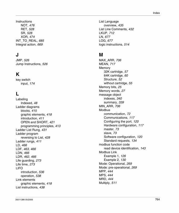
Index
InstructionsNOT, 476RET, 528SR, 528XOR, 474
INT_TO_REAL, 685Integral action, 669
JJMP, 526Jump Instructions, 526
Kkey switch
input, 174
LLabeling
Indexed, 48Ladder diagrams
blocks, 415graphic elements, 418introduction, 411OPEN and SHORT, 421programming principles, 413
Ladder List Rung, 431Ladder program
reversing to List, 428Ladder rungs, 411LD, 466LDF, 463, 466LDN, 466LDR, 462, 466Life guarding, 273Life time, 273LIFO
introduction, 536operation, 538
Link elementsgraphic elements, 418
List instructions, 438
35011386 05/2009
List Languageoverview, 435
List Line Comments, 432LKUP, 712LN, 677LOG, 677logic instructions, 514
MMAX_ARR, 706MEAN, 717Memory
32K cartridge, 5764K cartridge, 60Structure, 52without cartridge, 55
Memory bits, 25Memory words, 27message object
indexes, 340summary, 339
MIN_ARR, 706Modbus
communication, 72Communications, 117Configuring the port, 120Hardware configuration, 117master, 73slave, 73Software configuration, 120Standard requests, 134
modbus function coderead device identification, 143
Modbus LinkExample 1, 126Example 2, 130
Mode: Operational, 269Mode: pre-operational, 269MPP, 444MPS, 444MRD, 444Multiply, 511
764
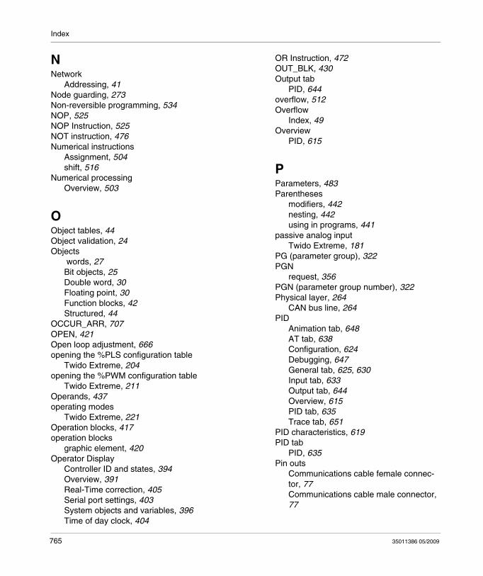
Index
NNetwork
Addressing, 41Node guarding, 273Non-reversible programming, 534NOP, 525NOP Instruction, 525NOT instruction, 476Numerical instructions
Assignment, 504shift, 516
Numerical processingOverview, 503
OObject tables, 44Object validation, 24Objects
words, 27Bit objects, 25Double word, 30Floating point, 30Function blocks, 42Structured, 44
OCCUR_ARR, 707OPEN, 421Open loop adjustment, 666opening the %PLS configuration table
Twido Extreme, 204opening the %PWM configuration table
Twido Extreme, 211Operands, 437operating modes
Twido Extreme, 221Operation blocks, 417operation blocks
graphic element, 420Operator Display
Controller ID and states, 394Overview, 391Real-Time correction, 405Serial port settings, 403System objects and variables, 396Time of day clock, 404
765
OR Instruction, 472OUT_BLK, 430Output tab
PID, 644overflow, 512Overflow
Index, 49Overview
PID, 615
PParameters, 483Parentheses
modifiers, 442nesting, 442using in programs, 441
passive analog inputTwido Extreme, 181
PG (parameter group), 322PGN
request, 356PGN (parameter group number), 322Physical layer, 264
CAN bus line, 264PID
Animation tab, 648AT tab, 638Configuration, 624Debugging, 647General tab, 625, 630Input tab, 633Output tab, 644Overview, 615PID tab, 635Trace tab, 651
PID characteristics, 619PID tab
PID, 635Pin outs
Communications cable female connec-tor, 77Communications cable male connector, 77
35011386 05/2009
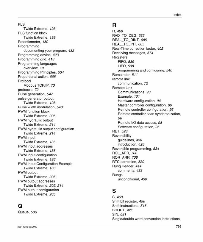
Index
PLSTwido Extreme, 198
PLS function blockTwido Extreme, 199
Potentiometer, 150Programming
documenting your program, 432Programming advice, 423Programming grid, 413Programming languages
overview, 19Programming Principles, 534Proportional action, 668Protocol
Modbus TCP/IP, 73protocols, 72Pulse generation, 547pulse generator output
Twido Extreme, 198Pulse width modulation, 543PWM function block
Twido Extreme, 206PWM hydraulic output
Twido Extreme, 214PWM hydraulic output configuration
Twido Extreme, 214PWM input
Twido Extreme, 186PWM input addresses
Twido Extreme, 186PWM input configuration
Twido Extreme, 186PWM Input Configuration Example
Twido Extreme, 188PWM output
Twido Extreme, 205PWM output addresses
Twido Extreme, 205, 214PWM output configuration
Twido Extreme, 205
QQueue, 536
35011386 05/2009
RR, 468RAD_TO_DEG, 683REAL_TO_DINT, 685REAL_TO_INT, 685Real-Time correction factor, 405Receiving messages, 574Registers
FIFO, 539LIFO, 538programming and configuring, 540
Remainder, 511remote link
communication, 72Remote Link
Communications, 93Example, 101Hardware configuration, 94Master controller configuration, 96Remote controller configuration, 96Remote controller scan synchronization, 96Remote I/O data access, 98Software configuration, 95
RET, 528Reversibility
guidelines, 430introduction, 428
Reversible programming, 534ROL_ARR, 708ROR_ARR, 708RTC correction, 580Rung Header, 414
comments, 433Rungs
unconditional, 430
SS, 468Shift bit register, 496Shift instructions, 516SHORT, 421SIN, 681Single/double word conversion instructions,
766
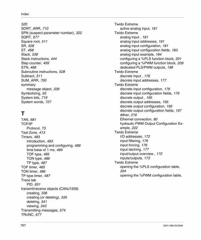
Index
520SORT_ARR, 710SPN (suspect parameter number), 322SQRT, 677Square root, 511SR, 528ST, 468Stack, 536Stack instructions, 444Step counter, 499STN, 468Subroutine instructions, 528Subtract, 511SUM_ARR, 700summary
message object, 339Symbolizing, 50System bits, 719System words, 727
TTAN, 681TCP/IP
Protocol, 73Test Zone, 413Timers, 483
introduction, 483programming and configuring, 488time base of 1 ms, 489TOF type, 485TON type, 486TP type, 487
TOF timer, 485TON timer, 486TP type timer, 487Trace tab
PID, 651transmit/receive objects (CANJ1939)
creating, 336creating (or deleting), 335deleting, 341viewing, 343
Transmitting messages, 574TRUNC, 677
767
Twido Extremeactive analog input, 181
Twido Extremeanalog input , 181analog input addresses, 181analog input configuration, 181analog input configuration fields, 183analog input example, 184configuring a %PLS function block, 201configuring a %PWM function block, 209dedicated PLS/PWM outputs, 198
Twido Extremediscrete input , 176discrete input addresses, 177
Twido Extremediscrete input configuration, 176discrete input configuration fields, 179discrete output , 195discrete output addresses, 195discrete output configuration, 195discrete output configuration fields, 197dither, 216Ethernet connection, 80hydraulic PWM Output Configuration Ex-ample, 222
Twido ExtremeI/O addresses, 172input filtering, 176input forcing, 176input latching, 177input/output overview , 172inputs/outputs, 173
Twido Extremeopening the %PLS configuration table, 204opening the %PWM configuration table,
35011386 05/2009
Index
211operating modes, 221passive analog input, 181PLS, 198PLS function blockj, 199pulse generator output, 198PWM function block, 206PWM hydraulic output , 214PWM hydraulic output configuration, 214PWM input , 186PWM input addresses, 186PWM input configuration, 186PWM Input Configuration Example, 188PWM output , 205PWM output addresses, 205, 214PWM output configuration, 205ramp, 217
TwidoSuiteIntroduction, 18
UUnconditional rungs, 430
VVery fast counters function block (%VFC), 559
WWord Objects, 532Word objects
Addressing, 35Function blocks, 42Overview, 27
XXOR, 474
35011386 05/2009
768
Index
769 35011386 05/2009