Embed Size (px)
Citation preview

TURBOVAC TW 70 H
Wide-Range TurbomolecularPump with Integrated or ExternalFrequency Converter
Operating Instructions
GA 05.145/3.02
Vacuum Solutions Application Support Service LEYBOLD VACUUM
GA 05.145/3.02 - 02/2001
Description
ContentsPage
1 Description . . . . . . . . . . . . . . . . . . . . . . . . . . . 21.1 Design . . . . . . . . . . . . . . . . . . . . . . . . . . . . . . 31.2 Standard equipment . . . . . . . . . . . . . . . . . . . . 31.3 Ordering data . . . . . . . . . . . . . . . . . . . . . . . . . 41.4 Technical data . . . . . . . . . . . . . . . . . . . . . . . . . 7
2 Connections . . . . . . . . . . . . . . . . . . . . . . . . . . 122.1 Operating environment . . . . . . . . . . . . . . . . . . 122.2 Attach the pump to the vacuum chamber . . . . . 132.3 Forevacuum connection . . . . . . . . . . . . . . . . . . 152.4 Connect the cooling . . . . . . . . . . . . . . . . . . . . . 172.5 Electrical connection . . . . . . . . . . . . . . . . . . . . 20
3 Operation . . . . . . . . . . . . . . . . . . . . . . . . . . . . 273.1 Switching on . . . . . . . . . . . . . . . . . . . . . . . . . . 273.2 Shutting down . . . . . . . . . . . . . . . . . . . . . . . . . 28 3.3 Venting . . . . . . . . . . . . . . . . . . . . . . . . . . . . . . 283.4 Bakeout . . . . . . . . . . . . . . . . . . . . . . . . . . . . . . 293.5 Removing the pump from the system . . . . . . . . 29
4 Maintenance . . . . . . . . . . . . . . . . . . . . . . . . . . 304.1 Cleaning . . . . . . . . . . . . . . . . . . . . . . . . . . . . . 304.2 Service by LEYBOLD . . . . . . . . . . . . . . . . . . . 30
5 Troubleshooting . . . . . . . . . . . . . . . . . . . . . . . 31EC Declarations . . . . . . . . . . . . . . . . . . . . . . . 34
FiguresThe references to the diagrams, e.g. (2/10), consist of the figu-re number and the item number, in that order.
WarningIdentifies working and operating procedures which must bestrictly observed to prevent hazards to persons.
CautionIndicates working and operating procedures which must bestrictly observed to prevent damage to or destruction of theappliance.
We reserve the right to alter the design or any data given inthese operating instructions.The illustrations are approximations.
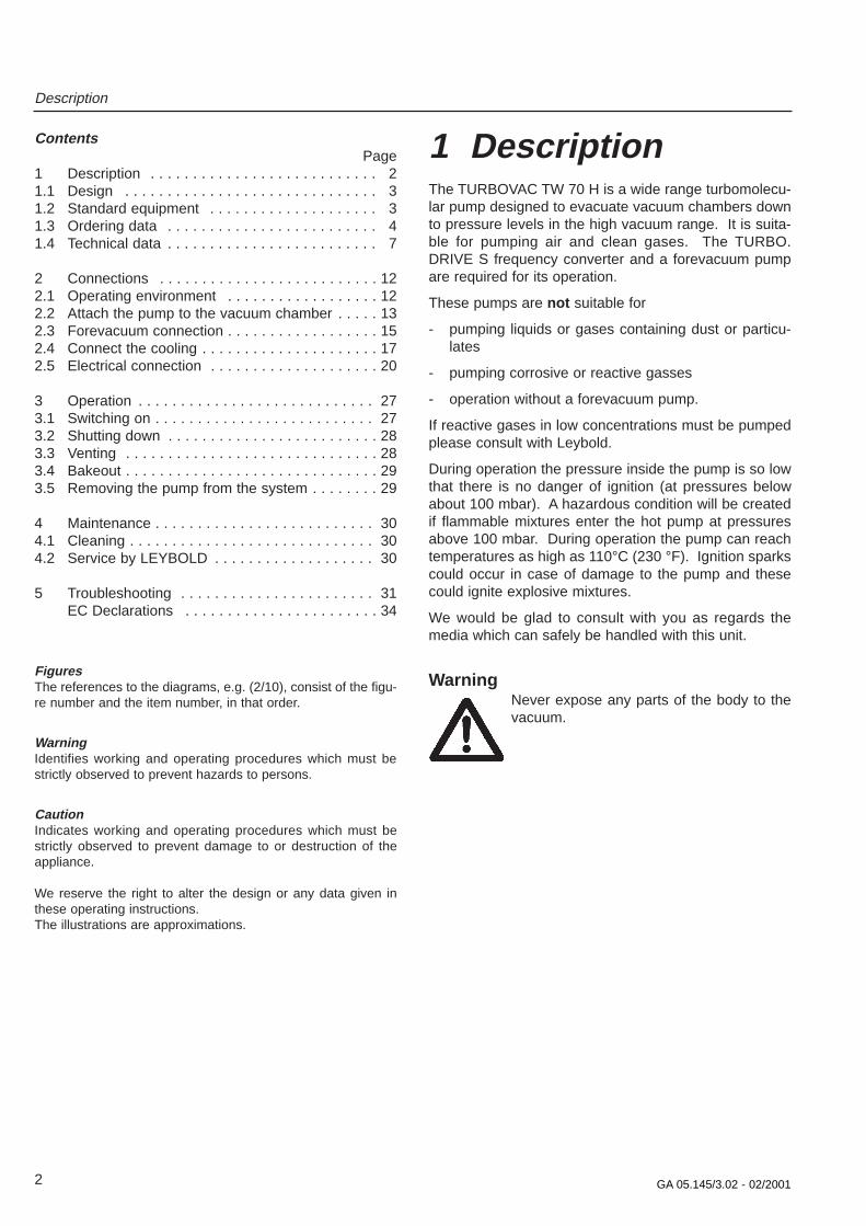
1 DescriptionThe TURBOVAC TW 70 H is a wide range turbomolecu-lar pump designed to evacuate vacuum chambers downto pressure levels in the high vacuum range. It is suita-ble for pumping air and clean gases. The TURBO.DRIVE S frequency converter and a forevacuum pumpare required for its operation.
These pumps are not suitable for
- pumping liquids or gases containing dust or particu-lates
- pumping corrosive or reactive gasses
- operation without a forevacuum pump.
If reactive gases in low concentrations must be pumpedplease consult with Leybold.
During operation the pressure inside the pump is so lowthat there is no danger of ignition (at pressures belowabout 100 mbar). A hazardous condition will be createdif flammable mixtures enter the hot pump at pressuresabove 100 mbar. During operation the pump can reachtemperatures as high as 110°C (230 °F). Ignition sparkscould occur in case of damage to the pump and thesecould ignite explosive mixtures.
We would be glad to consult with you as regards themedia which can safely be handled with this unit.
WarningNever expose any parts of the body to thevacuum.
2

GA 05.145/3.02 - 02/2001
Description
The pump connection cable is fixed and ready toconnect to the TURBO.DRIVE S frequency converter.
1.2 Standar d equipmentThe components of the pump are given in the orderingmatrix in Chapter 1.3.1 for each catalog number.
The pumps are shipped sealed in a PE bag with a desic-cant to absorb moisture.The maximum useful life of thedesiccant is one year.
The forevacuum flange is blank-flanged with centeringring with FPM sealing ring and a clamping yoke.
The high-vacuum connection elements and the splinterguard are not part of the standard equipment.
A suitable DC coupling for the power supply is included:In the case of pumps with integrated frequency conver-ter it is supplied with the pump, in the case of pumps witha separate frequency converter it is supplied with the fre-quency converter.
————————————PE = PolyethyleneFPM = Fluororubber, resistant to temperatures up to 150°C (302 °F)
3
1.1 DesignThe pumps comprise essentially the pump housing, amulti-stage rotor with the stator group, and the drive.
The first section of the rotor is a turbomolecular pumprotor while the second tile represents a Holweck stage.The Holweck pumping stage increases the permissibleforevacuum pressure level markedly when comparedwith the classic turbomolecular pump.
The rotor shaft runs in two ceramic ball bearings, lubri-cated with grease.
The pump is driven by a split-cage DC motor. In thismotor the rotor and stator windings are separated by avacuum-tight can. Consequently the rotor runs insidethe vacuum while the stator is outside the vacuum. Thiseliminates any need of vacuum feedthroughs.
The pump is equipped with a temperature sensor and aresistor code.
Water cooling or an air cooling fan is available as optio-nal equipment.
The intake flange should be fitted with a wire mesh splin-ter guard to protect the pump against mechanical dama-ge caused by foreign objects.
A plastic vacuum hose can be fitted directly to the fore-vacuum flange using a new high-vacuum tight portfitting, or a DN 16 KF flange is available.
Fig. 1 Section through a TURBOVAC TW 70 H
High-vacuum flange
Rotor turbo stage
Stator
Bearing
Rotor Holweck stage
Motor
Bearing
Forevacuum connection
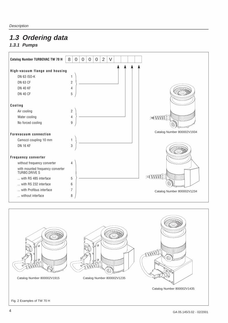
Catalog Number TURBOVAC TW 70 H
High-vacuum f lange and housing
DN 63 ISO-K 1
DN 63 CF 2
DN 40 KF 4
DN 40 CF 5
Cooling
Air cooling 2
Water cooling 4
No forced cooling 9
Forevacuum connect ion
Camozzi coupling 10 mm 1
DN 16 KF 3
Frequency converter
without frequency converter 4
with mounted frequency converterTURBO.DRIVE S
... with RS 485 interface 5
... with RS 232 interface 6
... with Profibus interface 7
... without interface 8
Description
4 GA 05.145/3.02 - 02/2001
1.3 Ordering data1.3.1 Pumps
8 0 0 0 0 2 V
Fig. 2 Examples of TW 70 H
Catalog Number 800002V1934
Catalog Number 800002V1435
Catalog Number 800002V1234
Catalog Number 800002V1915 Catalog Number 800002V1235
Description
5GA 05.145/3.02 - 02/2001
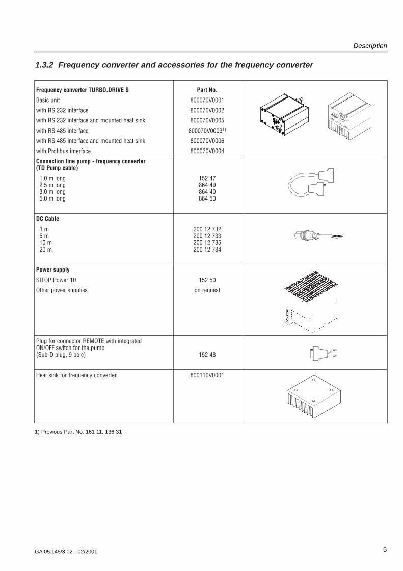
Frequency converter TURBO.DRIVE S Part No.
Basic unit 800070V0001
with RS 232 interface 800070V0002
with RS 232 interface and mounted heat sink 800070V0005
with RS 485 interface 800070V00031)
with RS 485 interface and mounted heat sink 800070V0006
with Profibus interface 800070V0004
Connection line pump - frequency converter (TD Pump cable)
1.0 m long 152 472.5 m long 864 493.0 m long 864 405.0 m long 864 50
DC Cable
3 m 200 12 7325 m 200 12 73310 m 200 12 73520 m 200 12 734
Power supply
SITOP Power 10 152 50
Other power supplies on request
Plug for connector REMOTE with integrated ON/OFF switch for the pump (Sub-D plug, 9 pole) 152 48
Heat sink for frequency converter 800110V0001
1.3.2 Frequenc y con ver ter and accessories f or the frequenc y con ver ter
on
off
Drive (X3)
HEAT SINK
DC 24 V(X4)
1) Previous Part No. 161 11, 136 31

Description
6 GA 05.145/3.02 - 02/2001
1.3.3 Accessories f or the pump
Part No.
Splinter guard fine 200 17 170
Camozzi coupling 200 04 361
Water cooling with connection G 1/8” 800135V0001
(for fitting to pumps without forced cooling)
Adapter G 1/8” - 1/4” Swagelok
Tube connector G 1/8“ outer dia. 10 mm 200 18 366
Tube connector G 1/8“ outer dia. 8 mm 800 000 273
Sealing ring 10x14x1 224 01 207
Air cooling 800136V0001
(for fitting to pumps without forced cooling)
Flange heater (only for pumps with CF flange)DN 63 CF, 230 V 854 04DN 63 CF, 110 V 854 07DN 40 CF, 230 V 853 97
Copper gasket rings for CF flange (Set of 10 pieces)DN 63 CF 839 44DN 40 CF 839 43
Set of hex. screws with nuts, screwsand washers for CF flange
DN 63 CF 838 81DN 40 CF 839 01
Centering ring (Al) with O-ring (FPM)DN 63 ISO-K 268 41
Clamps (Set of 4 pieces) 267 01
Centering ring with O-ring for DN 16 KFAl/CR 183 26Al/FPM 182 06
Centering ring with O-ring for DN 40 KFAl/CR 183 28Al/FPM 182 08
Clamping ring (Al) DN 16 KF 183 41
Clamping ring (Al) DN 40 KF 183 43

Description
7GA 05.145/3.02 - 02/2001
1.4 Technical data1.4.1 TURBOVAC TW 70 H—————————————————————————————————————————————————————————High-vacuum connection DN 63 ISO-K / DN 63 CF
DN 40 KF / DN 40 CF
Pumping speed (without splinter guard)for N2 65 l·s-1
He 55 l·s-1
Ultimate pressurewith two-stage, oil-sealed rotary vane pump < 10-9 mbar
with diaphragm pump achievingultimate pressure < 5 mbar < 10-7 mbar
Max. permissible forevacuum pressure 10 mbar
Weight Pump 2.3 kgPump with TURBO.DRIVE S 3.0 kgPump with TURBO.DRIVE S and air cooler 3.2 kgPump with TURBO.DRIVE S and water cooler 3.3 kg
Recommended forevacuum pumps• TRIVAC D 2.5 E
• Diaphragm pump DIVAC 0.8 T
Operating speed 72,000 rpm
Run-up time 1.5 min
Forevacuum connection DN 16 KF or Camozzi coupling
Type of protection IP 20
Noise level < 46 dB(A)
Ambient temperature during operation + 15 - + 45 °Cstorage – 15 - + 70°C
Max. rel. air humidity approx. 95%1)
(non-condensing)
Option pump with water cooling
Cooling water connections G 1/8“
Cooling water data see Section 2.4
1) More details in Applied technical standard IEC 721-3-3 3K3/ 3Z1/ 3B1/ 3C1/ 3S2/ 3M1
Description
8 GA 05.145/3.02 - 02/2001
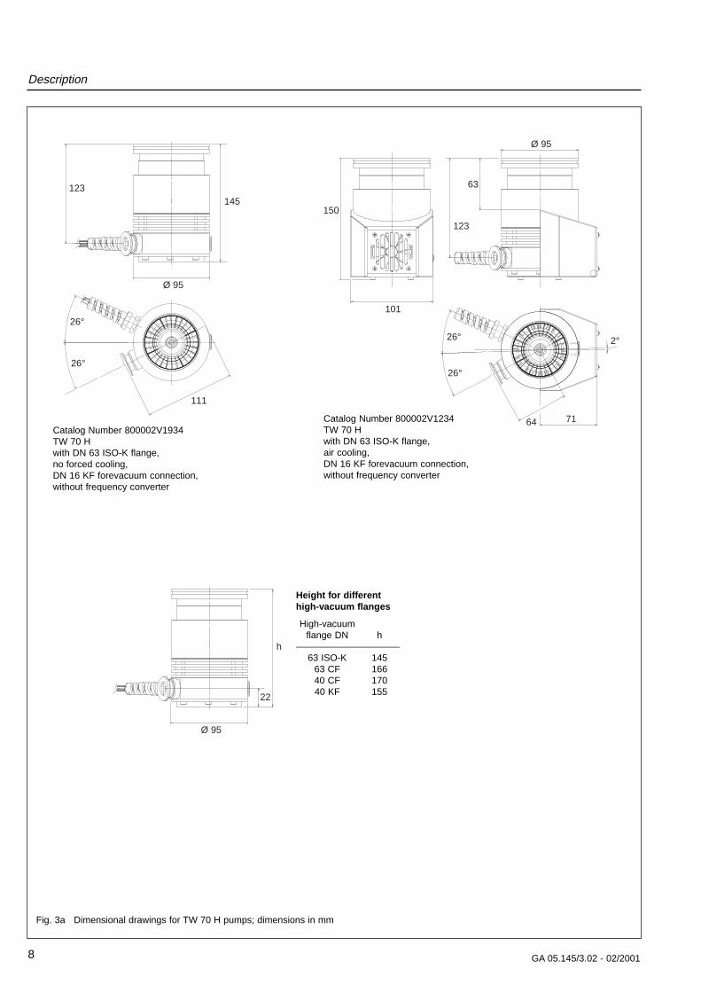
Fig. 3a Dimensional drawings for TW 70 H pumps; dimensions in mm
26°
26°
Ø 95
123145
111
Catalog Number 800002V1934TW 70 H with DN 63 ISO-K flange, no forced cooling,DN 16 KF forevacuum connection, without frequency converter
26°
26° 2°
Ø 95
123
63
7164
101
150
Catalog Number 800002V1234TW 70 H with DN 63 ISO-K flange, air cooling,DN 16 KF forevacuum connection, without frequency converter
Ø 95
22
h
Height f or diff erent high-v acuum flang es
High-vacuumflange DN h
———————————63 ISO-K 145
63 CF 16640 CF 17040 KF 155

Description
9GA 05.145/3.02 - 02/2001
152.5
64
26°26°
2°
100
156
Ø 95
123
147
Catalog Number 800002V1915TW 70 H with DN 63 ISO-K flange, no forced cooling,Camozzi forevacuum connection, with frequency converter
26°26°
Ø 95
2°
100
106
111
75
105
123
156
240
Catalog Number 800002V1435TW 70 H with DN 63 ISO-K flange, water cooling,DN 16 KF forevacuum connection,with frequency converter
TURB
O.DR
IVE
S
123
DN 63 ISO-KØ 95
148
71
64
50.5155.5
26°
2°
106
Fig. 3b Dimensional drawings for TW 70 H pumps; dimensions in mm
Catalog Number 800002V1235TW 70 H with DN 63 ISO-K flange, air cooling,DN 16 KF forevacuum connection, with frequency converter
Cable length 400 mm
Description
10 GA 05.145/3.02 - 02/2001
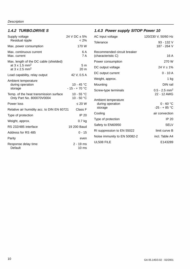
1.4.2 TURBO.DRIVE SSupply voltage 24 V DC ± 5%
Residual ripple < 2%
Max. power consumption 170 W
Max. continuous current 6 AMax. current 7 A
Max. length of the DC cable (shielded)at 3 x 1.5 mm2 5 mat 3 x 2.5 mm2 20 m
Load capability, relay output 42 V, 0.5 A
Ambient temperature during operation 10 - 45 °Cstorage - 15 - + 70 °C
Temp. of the heat transmission surface 10 - 55 °COnly Part No. 800070V0004 10 - 50 °C
Power loss ≤ 20 W
Relative air humidity acc. to DIN EN 60721 Class F
Type of protection IP 20
Weight, approx. 0.7 kg
RS 232/485 interface 19 200 Baud
Address for RS 485 0 - 15
Parity even
Response delay time 2 - 19 msDefault 10 ms
1.4.3 Power suppl y SITOP Power 10AC input voltage 120/230 V, 50/60 Hz
Tolerance 93 - 132 V187 - 264 V
Recommended circuit breaker(characteristic C) 16 A
Power consumption 270 W
DC output voltage 24 V ± 1%
DC output current 0 - 10 A
Weight, approx. 1 kg
Mounting DIN rail
Screw-type terminals 0.5 - 2.5 mm2
22 - 12 AWG
Ambient temperatureduring operation 0 - 60 °Cstorage -25 - + 85 °C
Cooling air convection
Type of protection IP 20
Safety to EN60950 SELV
RI suppression to EN 55022 limit curve B
Noise immunity to EN 50082-2 incl. Table A4
UL508 FILE E143289
Description
11GA 05.145/3.02 - 02/2001
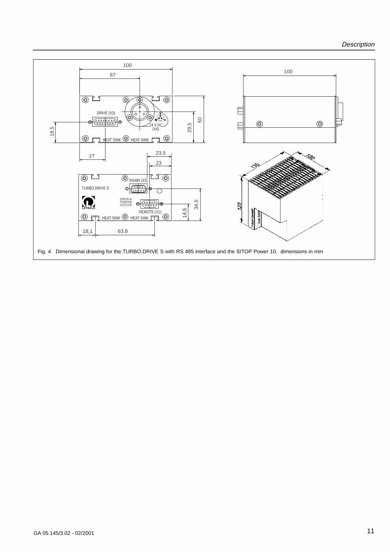
27
67
18,5 29
,5
100
50
100
23
23,5
34,5
18,1 63,8
DRIVE (X3)
24 V DC(X4)
RS485 (X5)
REMOTE (X1)
ERRORPOWERSTATUS
14,5
TURBO.DRIVE S
HEAT SINK
HEAT SINK
HEAT SINK
HEAT SINK
Fig. 4 Dimensional drawing for the TURBO.DRIVE S with RS 485 interface and the SITOP Power 10, dimensions in mm

Connections
12 GA 05.145/3.02 - 02/2001
2 ConnectionsCaution
The pumps are not suitable for pumpingaggressive or corrosive media or thosewhich contain dust.
Install a micropore filter when pumpingmedia which contains dust.Observe the information on media compati-bility at the beginning of these operatinginstructions.
Do not open the packaging until immediately beforeinstallation.
Do not remove the covers and blind flanges on the pumpuntil just before attachment to the equipment to ensurethat assembly is carried out under the cleanest possibleconditions.
CautionNever touch the rotor. Touching the rotormay cause injury and damage the rotorbearing.
WarningDuring operation the pump can become sohot that there is a danger of burns (up toapprox. 80 °C, 176 °F).Provide protection against contact with thehot components.
2.1 Operating en vir onmentThe maximum permissible ambient temperature is 45 °C(113 °F). Do not expose the pump or the frequency con-verter to dripping or spraying water
If the pump is used within a magnetic field, the magneticinduction at the surface of the pump housing may notexceed:
B = 5 mT if impinging radially and
B = 15 mT if impinging axially.
Install shielding equipment as appropriate if these valuesare exceeded.
The standard pump version without frequency converteris resistant to radiation up to 103 Gy.
Places of installation up to 1000 m above sea level (3300 ft) are possible without restrictions. At altitudesover 1000 m heat dissipation by the ambient air is impai-red. Please consult us.
——————————————1 mT (milliTesla) = 10 G (Gauß)1 Gy (Gray) = 100 rad

Connections
13GA 05.145/3.02 - 02/2001
No support is required. If nonetheless an additionalfastening is requested you can use the 3 boreholes inthe pump’s bottom. A rubber foot must be removed fromone of the boreholes.
CautionIf foreign objects could pass from the vacu-um chamber into the pump, install a wiremesh splinter guard. Foreign objects whichenter the pump through the intake wouldcause serious damage to the rotor. Dama-ge resulting from foreign objects in the rotorsection are excluded from guarantee cover-age.
Insert the splinter guard so that the surface curvature isat the top and apply some pressure lightly at the rim sothat the splinter guard engages.
If dust could pass from the vacuum chamber into thepump, then a micropore filter must be installed betweenthe vacuum chamber and the pump.
The pump is precision balanced and is generally opera-ted without a resonance damper. To decouple extremelysensitive equipment and to prevent transfer of externalvibrations to the pump a special resonance damper isavailable for mounting at the high-vacuum flange.
Detach the shipping flange from the high-vacuum flangeand remove the desiccant. Pay attention to scrupulouscleanliness when making the connection.
2.2 Attac h the pump to thevacuum c hamber
WarningThe high-vacuum flange must be solidlymounted to the vacuum chamber. If themounting is not sturdy enough, pump block-age could cause the pump to break loose;internal pump components could be thrownin all directions. Never operate the pump (inbench testing, for example) without properflanging to the vacuum chamber.
If the pump should suddenly seize, an ensuing deceler-ation torque of up to 470 Nm will have to be absorbed bythe system. To accomplish this, • 4 clamping bolts quality 12.9 or • 6 clamping bolts quality 8.8 are required for securing an ISO-K type high-vacuumflange.
Clamping bolts made of steel must be torqued down to35 Nm (26 ft-lb), those made of stainless steel to 50 Nm37 ft-lb).
In most applications the pump is flanged to the high-vacuum flange at the apparatus. The pump can bemounted and operated in any desired attitude.
Fig. 5 Connection elements
High-vacuum connection flange
Connection cable toTURBO.DRIVE
Forevacuum connection
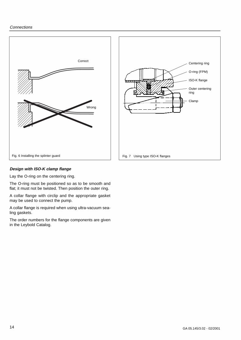
Design with ISO-K c lamp flang e
Lay the O-ring on the centering ring.
The O-ring must be positioned so as to be smooth andflat; it must not be twisted. Then position the outer ring.
A collar flange with circlip and the appropriate gasketmay be used to connect the pump.
A collar flange is required when using ultra-vacuum sea-ling gaskets.
The order numbers for the flange components are givenin the Leybold Catalog.
Connections
14 GA 05.145/3.02 - 02/2001
Fig. 7 Using type ISO-K flanges
Centering ring
O-ring (FPM)
ISO-K flange
Outer centeringring
Clamp
Correct
Wrong
Fig. 6 Installing the splinter guard

Connections
2.3 Forevacuum connectionThe high vacuum pressure level which can be achievedis a function of the volume of gas flow Q to be pumpedand the forevacuum pressure.
We recommend using dry-running diaphragm vacuumpumps or TRIVAC rotary vane pump for this purpose.
For the forevacuum connection a vacuum hose Ø 10 x 8mm will be needed. We recommend a polyamide hose.
Remove the shipping cap from the forevacuum connec-tion. Pull the rear ring and push the forevacuum hoseinto the connector. Release the ring. The hose will befixed.
Alternatively you may unscrew the hose connector anduse the R 3/8“ screw connection for the forevacuumconnection.
WarningThe forevacuum line must be tight. Hazar-dous gases can escape at leaks or thegases being pumped can react with air orhumidity.
Figure 13 is a schematic diagram of a pump systemincorporating a turbomolecular pump and a TRIVACforevacuum pump with an anti-suckback valve.
A separate safety valve must be provided for oil-sealedforevacuum pumps without an anti-suckback valve. Thesafety valve prevents oil flowing back from the forevacu-um pump into the turbomolecular pump when the systemis not running.
To ensure that the forevacuum space at the turbomole-cular pump is kept largely free of oil vapors during ope-ration, as well, we recommend installing an adsorptiontrap in the forevacuum line. Alternatively purge the fore-vacuum line with inert gas. In this case the pressure inthe forevacuum line must be over 10-2 mbar.
Provide a roughing line to achieve the shortest cycletimes.
Ensure that the pump is sufficiently isolated againstvibrations generated by the forevacuum pump.
15GA 05.145/3.02 - 02/2001
Fig. 8 Forevacuum connection with Camozzi coupling
Connections
16 GA 05.145/3.02 - 02/2001
°C
50
40
30
20
10
0
l/h
5 10 15 20 25 30 35 40
60
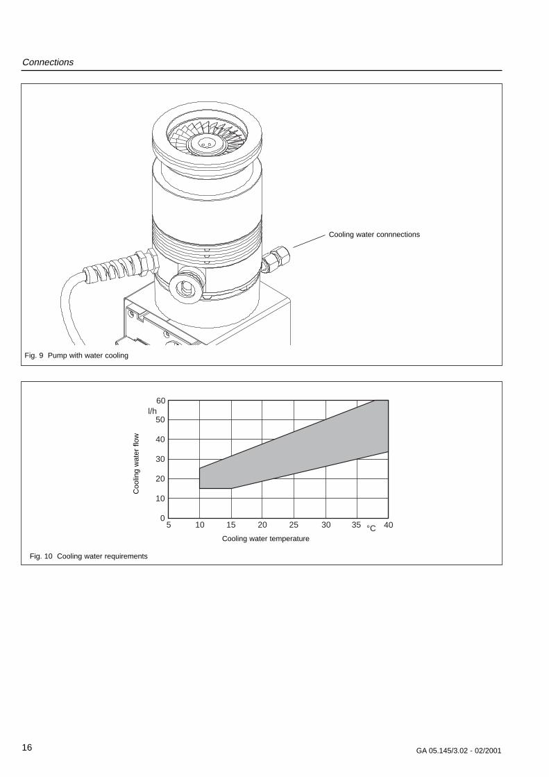
Fig. 10 Cooling water requirements
Coo
ling
wat
er f
low
Cooling water temperature
Fig. 9 Pump with water cooling
Cooling water connnections
Connections
17GA 05.145/3.02 - 02/2001
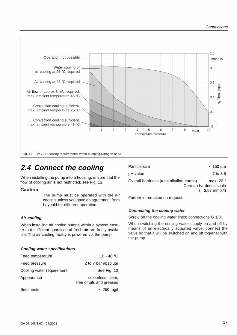
2.4 Connect the coolingWhen installing the pump into a housing, ensure that theflow of cooling air is not restricted; see Fig. 12.
CautionThe pump must be operated with the aircooling unless you have an agreement fromLeybold for different operation.
Air cooling
When installing air cooled pumps within a system ensu-re that sufficient quantities of fresh air are freely availa-ble. The air cooling facility is powered via the pump.
Cooling water specifications
Feed temperature 10 - 40 °C
Feed pressure 2 to 7 bar absolute
Cooling water requirement See Fig. 10
Appearance colourless, clear, free of oils and greases
Sediments < 250 mg/l
Particle size < 150 µm
pH value 7 to 8.5
Overall hardness (total alkaline earths) max. 20 °German hardness scale
(= 3.57 mmol/l)
Further information on request.
Connecting the cooling water
Screw on the cooling water lines; connections G 1/8”.
When switching the cooling water supply on and off bymeans of an electrically actuated valve, connect thevalve so that it will be switched on and off together withthe pump.
0
0.2
0.4
0.6
0.8
1.0
0 1 2 3 4 5 6 7 8
9
10
Operation not possible
Water cooling or air cooling at 25 °C required
Air cooling at 45 °C required
Air flow of approx 5 m/s required, max. ambient temperature 45 °C
Convection cooling sufficient, max. ambient temperature 25 °C
Convection cooling sufficient, max. ambient temperature 45 °C
Fig. 11 TW 70 H cooling requirements when pumping Nitrogen or air
Forevacuum pressurembar
N2
Thr
ough
put
mbar·l/s

Connections
18 GA 05.145/3.02 - 02/2001
Fig.12 Pump with air cooling
Fig.13 Schematic of a turbomolecular pump system
Legend for Fig. 131 Turbomolecular pump2 Forevacuum gauge port3 Forevacuum pump4 Resonance damper5 Adsorption trap6 Forevacuum valve7 High-vacuum valve8 Valve in the roughing pump line9 Frequency converter
— — — — Roughing line; recommend toachieve the shortest possible cycle times
Connections
19GA 05.145/3.02 - 02/2001
Power supply24 V DC cable,
max. 20 m
Mains
24 V DC cable,max. 5 m
Power supply
24 V DC cable,max. 20 mMains
DC cable, with shielding,
max. 20 m
Mains
Power supply
24 V DC cable, max. 5 m
DC cable, with shielding,
max. 20 m
Mains
Power supply
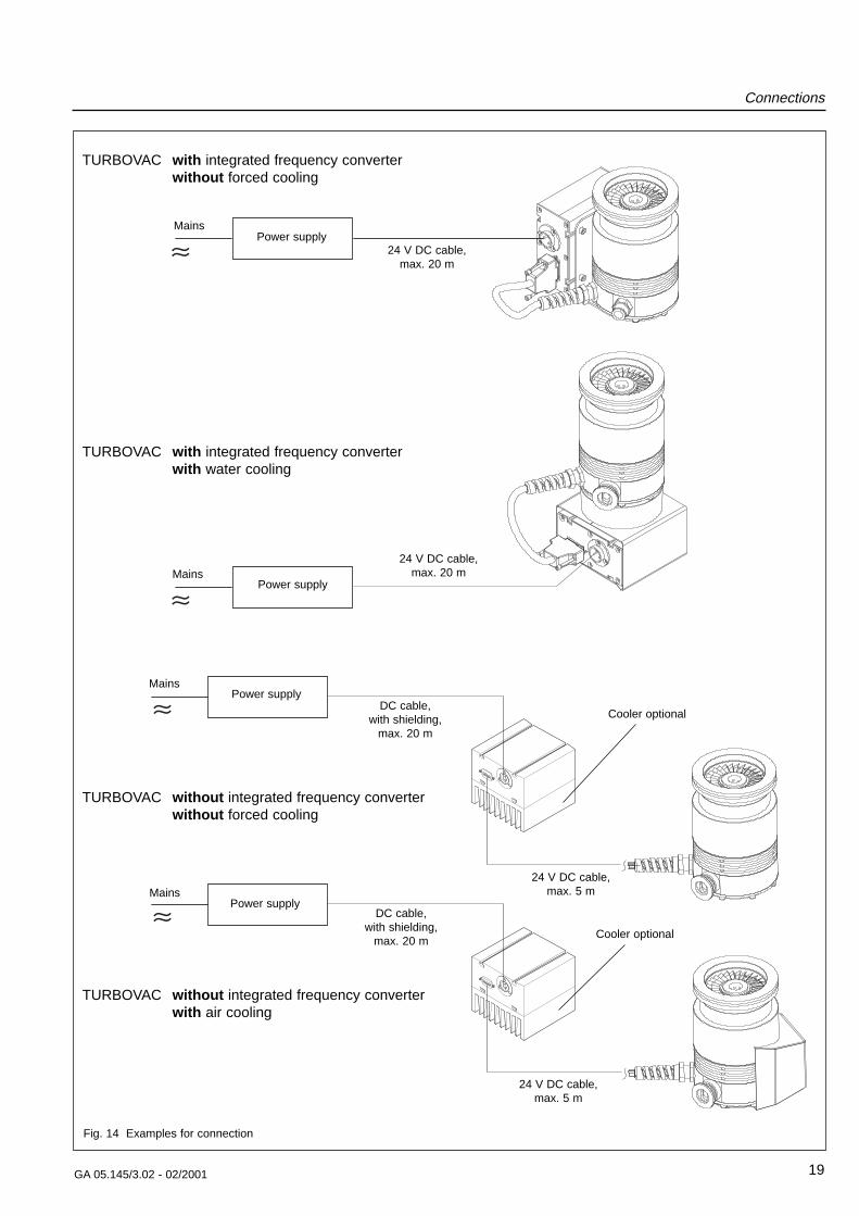
TURBOVAC with integrated frequency converterwithout forced cooling
TURBOVAC with integrated frequency converterwith water cooling
TURBOVAC without integrated frequency converterwithout forced cooling
TURBOVAC without integrated frequency converterwith air cooling
Fig. 14 Examples for connection
Cooler optional
Cooler optional
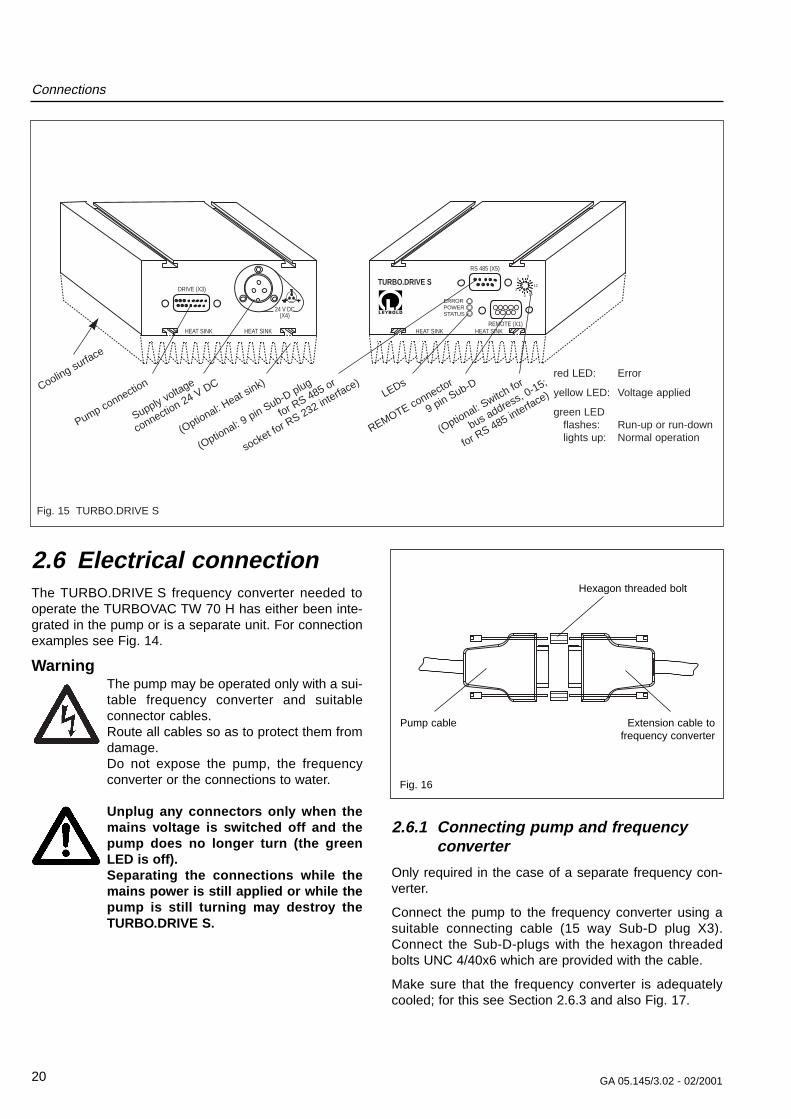
2.6 Electrical connectionThe TURBO.DRIVE S frequency converter needed tooperate the TURBOVAC TW 70 H has either been inte-grated in the pump or is a separate unit. For connectionexamples see Fig. 14.
WarningThe pump may be operated only with a sui-table frequency converter and suitableconnector cables.Route all cables so as to protect them fromdamage.Do not expose the pump, the frequencyconverter or the connections to water.
Unplug an y connector s onl y when themains v olta ge is s witc hed off and thepump does no long er turn (the greenLED is off).Separating the connections while themains po wer is still applied or while thepump is still turning ma y destr oy theTURBO.DRIVE S.
2.6.1 Connecting pump and frequenc yconver ter
Only required in the case of a separate frequency con-verter.
Connect the pump to the frequency converter using asuitable connecting cable (15 way Sub-D plug X3).Connect the Sub-D-plugs with the hexagon threadedbolts UNC 4/40x6 which are provided with the cable.
Make sure that the frequency converter is adequatelycooled; for this see Section 2.6.3 and also Fig. 17.
Connections
20 GA 05.145/3.02 - 02/2001
DRIVE (X3)
ERRORPOWERSTATUS
REMOTE (X1)
RS 485 (X5)
TURBO.DRIVE S 15
12
96
0
3
HEAT SINK
24 V DC(X4)
HEAT SINK HEAT SINK HEAT SINK
Pump connection
Supply voltage
connection 24 V DC
(Optional: Heat sink)
(Optional: 9 pin Sub-D plug
for RS 485 or
socket for R
S 232 interface)
LEDs
REMOTE connector
9 pin Sub-D
(Optional: Switch for
bus address, 0-15;
for RS 485 interfa
ce)
red LED: Error
yellow LED: Voltage applied
green LED flashes: Run-up or run-downlights up: Normal operation
Cooling surface
Fig. 15 TURBO.DRIVE S
Fig. 16
Pump cable Extension cable tofrequency converter
Hexagon threaded bolt

Connections
21GA 05.145/3.02 - 02/2001
2.6.2 Connecting the po wer suppl y
WarningThe frequency converter must only beconnected to power supplies which meetthe requirements for functional extra lowvoltage with positive isolation in accordancewith IEC 364 (VDE 0100, Part 410, or localregulations) (SELV).
The power supply must meet the requirements given inSection 1.4.3. Peak loads in the kHz range may be pre-sent on the DC side. The power supply should have acurrent limitation or control.
Connect the frequency converter to the 24 V DC powersupply at the DC connector X4; see Fig. 19.
CautionEnsure correct polarity.Pin 1 + 24 VDCPin 2 0 VPin 3 GND
Connect the power supply to the mains.
2.6.3 Mounting the frequenc y con ver ter
The frequency converter can be mounted into a rack.The bottom side of the frequency converter must be coo-led sufficiently.
If the frequency converter is installed without the optio-nal cooling fins, adequate cooling must be ensured byother means.
The cooling surface of the frequency converter must notwarm up to more than 55 °C (113 °F). When mountingthe frequency converter on existing cooling surfacesensure good surface contact.
For special requirements please contact Leybold.
The frequency converter has an internal SMD fuse T 10A. It can only be changed by the Leybold Service.
1 2 3 4 5 A
60
50
40
30
20
10
0
°C
6
Fig. 17 Cooling requirements for the TURBO.DRIVE S when fitted separately
Motor current
Am
bien
t te
mpe
ratu
re
Operation possible without additional cooling
Heat sink required(convection cooling)
Heat sink and forced cooling required
1
2
3
Pin 1 24 V
Pin 2 0 V
Pin 3 GND Shielding
Fig. 18 Pin assignment of the DC connector (X4) Model Hirose HS16P-3

22 GA 05.145/3.02 - 02/2001
Connections
(RS 485 / 232)REMOTE
93 - 132 /187 - 264V AC,50/60 Hz
24 V DC
L1
N
PE
120 V
AC
L+
M
M
+ 24 V DC
0 V DC
GND
LED POWER
DRIVE (X3)
HEAT SINK
24 V DC(X4)
HEAT SINK
Fig. 19 Connection of the power supply and the TURBO.DRIVE S
Optional jumper foroperating voltage range93 - 132 V
12 V
TURBO.DRIVE S
8
7
6
0 V = STOP24 V = START
12 V
TURBO.DRIVE S
8
7
6
Fig. 20 Pin assignment of the REMOTE (X1) connector
Relay operation
8 7 6
5 4 3 2 1
9
Pin assignment of the connector
12 V
10 kΩ5 V
10 kΩ
10 kΩ
TURBO.DRIVE S
8
7
6
Pin assignment for the Start/Stop input
Switching thresholdfor the Start/Stop con-trol input:Low level: < 3 VHigh level: > 7 V
Start/Stop operationExample 1: Operation via a PLC
Contact open = STOPContact closed = START
Example 2: Operation via contacts
TURBO.DRIVE S
534
n. c.n. o.com.
291
n. c.n. o.com.
Relay - Normal operation• While deceleration, acceleration, Stop:
4 connected to 5 (as shown; passive)• During normal operation (f > 0,9·fnom.):
4 connected to 3 (active)
Relay - Err or• No error: 1 connected to 2 (as shown; passive)• Error is present: 1 connected to 9 (active)

Connections
23GA 05.145/3.02 - 02/2001
2.6.4 Interface description
The frequency converter has an optional serial interfaceRS 485. It is operated with the standardized USS proto-col. The frequency converter can be set to addresses 0to 15. Addresses over 15 are not supported.
For more detailed information concerning the USS pro-tocol please contact Leybold.
The RS 485 bus should be connected as shown in Fig.22.
The frequency converter can be configured through theparameters shown in the parameter list.
As to the RS 232 and Profibus interfaces please enqui-re.
Input data / status Output data Operating modeStart/ Pump Normal Error is Motor Relay Relay LED LEDstop rotating frequency present drive NORMAL ERROR STATUS ERROR
signal ≥ 90% of OPERATIONsetpoint
frequency
Stop no no no off passive passive off off Pump not operating
Stop yes no no off passive passive flashes off Pump is decelerating
Stop yes yes no off passive passive flashes off Just after stop; pump was in the normal operating mode before that
Start no no no on passive passive off off Just after start
Start yes no no on passive passive flashes off Pump is accelerating
Start yes yes no on active passive green off Pump is in the normal operating mode
Stop no no yes off passive active off red Error is present; pump is at standstill
Stop yes no yes off passive active flashes red Error is present; pump is decelerating
Stop yes yes yes off passive active flashes red Error has just occurred
Start no no yes off passive active off red Error is present; pump is at standstill
Start yes no yes off passive active flashes red Error is present; pump is decelerating
Start yes yes yes off passive active flashes red Error has just occurred
Relay status
Other modes are not possible; they indicatea failure affecting the TURBO.DRIVE S.
7
8
9
1
2
3
45
6
TxD/RxD +
TxD/RxD –
0,5 A, 24 V DC
Fig. 21 Pin assignment of the interface connector „RS 485“
Links for activation ofthe bus terminator

Connections
24 GA 05.145/3.02 - 02/2001
+ 5 V
390 Ω
150 Ω
390 Ω
X 5
(8)
(7)
TURBO.DRIVE
X5 (7) X5 (8) X5 (7) X5 (8)...
82 Ω
Master
X 5
(6)
(9)
TxD/RxD –
TxD/RxD +
150 Ω
TURBO.DRIVE
TURBO.DRIVE
Fig. 22 Connection of the RS 485 bus
Links for activation of thebus terminator
Bus terminator
No. Designation Range Unit Default Format r/w Description
0 Dummy parameter - - - U16 No function
1 Type of frequency 130 / 131 - - U16 r TURBO.DRIVE S = 130converter TURBO.DRIVE L = 131
2 Software version 2.x.x - - U16 r
3 Actual rotor frequency 0...1300 Hz - U16 r The max. frequency depends on thepump type.
4 Actual converter Nominal value for supply voltage 18...30 V - U16 r TURBO.DRIVE S: 24V
5 Actual motor current 0... 60 0,1A - U16 r
7 Actual motor- Measured coil temperature for the motor temperature 0...150 °C - U16 r
8 Permanently save the A write command will cause the data to bechanged parameter data saved. The parameter value itself is not in the EEPROM - - - U16 w processed and saved.
11 Actual convertertemperature 0...150 °C - U16 r Measured internal converter temperature
12 Operating mode for 0...2 - 0 U16 r/w P12 = 0 (default): via REMOTE (X1); Start/Stop see Fig. 20
P12 = 1: via serial interfaceP12 = 2: Start: REMOTE (X1) at Start andserial interface sends Start signalStop: REMOTE (X1) at Stop orserial interface sends Stop signal
Parameter list r = readable, w = writable

Connections
25GA 05.145/3.02 - 02/2001
No. Designation Range Unit Default Format r/w Description
17 Max value setting for motor current 5 ... 75 0,1 A 45 U16 r/w Maximum permissible motor current
18 Nominal pumpfrequency 750...1200 Hz 1200 U16 r Highest permissible frequency
19 Minimum setpoint frequency for the pump 375..600 Hz 600 U16 r Lowest permissible frequency
20 Minimum frequency r When the pump is accelerating this level frequency must be reached within the
375..600 Hz - U16 r maximum passing time (P183).
23 Pump type 0...4 - 3 U16 r
24 Setpoint frequency P19 ... P18 Hz 1200 U16 r/w Adjustable between P19 to P18
25 Frequency dependent If P29 = 0: Defines the normal operationnormal operation level 0..100 % 90 U16 r/w level. Normal operation if P3 ≥ P24 x P25
27 Motor current dependent If P29 = 1: Defines the normal operationnormal operation level 5...75 0,1 A 20 U16 r/w level. Normal operation if P5 ≤ P27
29 Selection of the normal Normal operation relay function:operation function 0 / 1 - 0 U16 r/w 0 = frequency dependent (see P25)
1 = current dependent (see P27)
32 Maximum run up time 30...2000 s 720 U16 r/w Max. permissible acceleration time from starting the pump’ s drive until reaching the normal operation level (P24 * P25)
36 Start delay time 0...255 0.1 min. 0 U16 r/w Pause time after the Start command until the pump’s drive is started
125 Current bearing temp. 0...150 °C U16 r Measured bearing temperature(identical to P127)
127 Current bearing temp. 0...150 °C - U16 r Measured bearing temperature(identical to P125)
132 Bearing temperature Max. permissible bearing temperatureshutdown level 30...150 °C 67 U16 r P125 > P132 causes the pump to be
switched off
133 Motor temperature Max. permissible motor temperatureshutdown level 30...150 °C 90 U16 r P7 > P133 causes the pump to be
switched off
171 Error code memory Sequential permanent memory;for the last 8 error events Array the last error code which has occurred Error codes see 0..7 is saved at the memory location with the next table 0...8 0 U16 r index 0, the oldest is at index 7
176 Error operating hours Array Analogous to P171memory for the last 8 0...19 0..7 (error code memory)error events years 0.01 h - U32 r
180 Response delay time 2...19 msec 10 U16 r/w Pause time between received and trans-mitted USS protocol string of the frequency converter’s serial interface. We recommend not to change the default setting (10 ms)
183 Max. passing time 10...2000 s 500 U16 r During acceleration the pump must passthrough the range of critical frequenciesfrom 60 Hz to P20

Connections
26 GA 05.145/3.02 - 02/2001
No. Designation Range Unit Default Format r/w Description
184 Converter operating 0...19 Totals the operating hours for the converterhours counter Years 0,01h - U32 r when the pump’s drive is active
303 Pump status word - - - U16 r Meaning of the bits:Bit 0 Normal operation = 1Bit 1 Ready for switch on = 2Bit 2 Speed is increasing = 4Bit 3 Speed is dropping = 8In case of an error P303 has the value of 0 (not ready to be switched on)
312 Cat. No. code 0 ... 65535 - - U16 r
315 Serial No. code 1 ... 231-1 - - U32 r The 9 resp. 10 least significant bits of theoriginal serial No.
316 Hardware identifier 0...100 - - U16 r Hardware version index of the converter
Error codes f or parameter P171
Code Type of error Description of the error0 No error –
1 Overspeed error Nominal speed of the pump (P 18) has been exceeded by over 10%
2 Pass through time error Max. pass through time during run up has been exceeded: from 60 Hz to minimumfrequency level; P3 < P20 after P183 has elapsed
3 Bearing temperature error Maximum bearing temperature has been exceeded: P125 > P132; P127 > P132
4 Short circuit error Short circuit in the pump’s motor or the connecting cable
5 Converter temperature error Maximum temperature for the converter has been exceeded: P11 > 65°C
6 Run up time error Maximum run up time during run up has been exceeded from starting to normal operation: P3 < P24 * P25 after P32 has elapsed
7 Motor temperature error Maximum motor temperature has been exceeded: P7 > P133
8 Pump error Pump could not be identified or no pump is connected.

Operation
27GA 05.145/3.02 - 02/2001
3 OperationWarning
The turbomolecular pump must only beoperated in the proper condition and underthe conditions described in the OperatingInstructions.
3.1 Switc hing onSwitch on the 24 V DC power supply. The yellow LED atthe frequency converter lights up.
The maximum starting pressure for the turbomolecularpump can be read from the graph in Figure 23.
Switch on the turbomolecular pump at the frequencyconverter
• by connecting contacts 7 and 8 at the REMOTE (X1)connector. (For example via a remote control or withthe aid of the plug with integrated ON/OFF switch:see Section 1.3 Ordering data)
or
• by a start command via the interface; see Section2.6.4.
For the power supply units offered or recommended byLeybold: If the contacts 7 and 8 at the REMOTE (X1)connector are closed the pump starts automaticallywhen the DC voltage is switched on (provided parame-ter 12 is set to 0).
The turbomolecular pump accelerates. The green LEDflashes. When the pump reaches normal operation thegreen LED lights up permanently.
Avoid the influences of shock and vibration when thepump is running.
WarningDuring operation the pump can become sohot that there is a danger of burns (up toapprox. 80°C, 176 °F).
WarningAfter a mains power failure the pump canrun up automatically once more.
103
102
101
100
mbar
0 25 50 75 100h
-1 125
Sv = Pumping speed of the forevacuum pump (m3·h-1)V = Volume of the vacuum chamber (m3)
Sv / V
Sta
rtin
g pr
essu
re
Fig. 23 Determining the starting pressure of a turbo-molecular pump when evacuating large volumes

Operation
28 GA 05.145/3.02 - 02/2001
3.2 Shutting do wnSwitch off the pump at the frequency converter.
• Disconnect contacts 7 and 8 at the REMOTE (X1)connector
or
• apply a stop command via the interface
or
• for the power supply units offered or recommendedby Leybold switch off the DC voltage.
Switch off the forevacuum pump.
When using oil-sealed forevacuum pumps, vent the tur-bomolecular pump before it comes to a stop; refer toSection 3.3.
When using TRIVAC pumps the built-in anti-suckbackvalve will close automatically, shutting off the forevacu-um line. In forevacuum pumps without a vacuum reten-tion valve, close the valve in the forevacuum line.
WarningUnplug any connectors only when themains voltage is switched off and the pumpdoes no longer turn (the green LED is off).
When the system is not operating, ensure that neitherambient air nor cleaning media can enter the pump.
If a failure occurs the turbomolecular pump will be shutdown automatically. The red LED at the frequency con-verter lights up.
3.3 VentingWhen using oil-sealed forevacuum pumps, vent thepump each time it is shut down to prevent possible returndiffusion of oil vapors from the forevacuum line to thehigh-vacuum side.
Use dry nitrogen, for example, for venting purposes.
The pump can be vented from the high-vacuum side.
When using a dry-running forevacuum pump, the pumpcan be vented via the forevacuum port.
When using oil-sealed forevacuum pumps do not ventthe pump through the forevacuum port since oil vaporscould enter the pump in this way.
The pump can be vented when it is running at full speed.
CautionThe values shown along the curve for pres-sure rise in Figure 24 must be maintained inall cases.
Fig. 24 Maximum rise in pressure
103
mbar
102
10
1
For
evac
uum
pre
ssur
e
0 5 10 15 20 25 30s
Time

Operation
29GA 05.145/3.02 - 02/2001
3.4 BakeoutFor TURBOVACs with CF flange
If pressures in the range of 10-8 mbar or below are to bedeveloped, the vacuum chamber and the componentsinstalled therein will have to be baked out. In addition,the TURBOVAC can be baked out using the flange heaterprovided for this purpose.
Protect the rotor against intensive, direct heat radiation.When baking out at the forevacuum side – at a sorptiontrap, for example – ensure that the components attacheddirect are not heated to more than 100 °C (212 °F).
The forevacuum pump must be in operation so as toeliminate the vapors liberated at the sorption trap.
3.5 Removing the pumpfrom the system
Shut down the pump and vent as described in Sections3.2 and 3.3.
WarningIf the pump has previously handled hazar-dous gases, implement the proper precau-tionary measures before opening the intakeor exhaust connection.
If necessary, use gloves, a respirator and/orprotective clothing and work under anexhaust hood.
Disconnect the pump only when it has come to a fullstop. The green LED at the frequency converter musthave gone out.
The pumps may be contaminated with process gases.These gases may be toxic and hazardous to health. Inaddition, deposits with similarly dangerous propertiesmay have formed. Many of these gases and depositsform acids when they come into contact with humid air.This will result in serious corrosion damage to the pump.
To avoid health hazards and corrosion damage when thepumps are detached from the system, fasten a containerof desiccant under the transport cover of the high-vacu-um connection and then close the pump immediately atall flange connections. Store the pump, with a desiccant,in an air-tight PE bag.
Corrosion damage due to faulty packing will nullify theguarantee.
Pack the pump so that it cannot be damaged duringshipping and storage. Pay particular attention to protec-tion for the flanges and the electrical plug.
Observe the instructions in Section 4.2 if you forward thepump to Leybold.
Maintenance
30 GA 05.145/3.02 - 02/2001
4 MaintenanceThe turbomolecular pump requires no routine mainten-ance.
When an adsorption trap is used, regenerate or renewthe adsorption agent regularly; refer to the operatinginstructions provided with the trap.
The frequency converter is maintenance free.
4.1 CleaningIf required clean the turbomolecular pump of dust with adry cloth.
4.2 Service b y LEYBOLDWhenever you send a pump to Leybold, indicatewhether the pump is contaminated or is free of sub-stances which could pose a health hazard. If it is conta-minated, specify exactly which substances are involved.You must use the form we have prepared for this purpo-se; we will forward the form on request.
A copy of the form is printed at the end of these opera-ting instructions: „Declaration of contamination of vacu-um equipment and components“.
Attach the form to the pump or enclose it with the pump.
This statement detailing the contamination is required tosatisfy legal requirements and for the protection of ouremployees.
Pumps which are not accompanied by a contaminationstatement will be returned to the sender.
Troubleshooting
31GA 05.145/3.02 - 02/2001
5 Troub leshootingWarning
When the connector cable is attached, theoutputs at the frequency converter are notfree of voltage.
Before you start searching for the source of the problem,you should carry out a few simple checks:
Are the connections in good working order?
• Mains connection,
• 24 V DC cable to the frequency converter,
• Connector cable between the frequency converterand the pump
Is the forevacuum pressure sufficient?
After having removed the cause for the error reset theerror message at the TURBO.DRIVE S:
• In case of errors with error codes 1 to 7 by applying aSTOP signal via the socket REMOTE (X1) or the seri-al interface or by switching the mains power off.
• In case of error code 8 by switching the mains poweroff.
The following table has been provided as a guide whendetermining the causes of errors.

Possible cause Corrective action
EMC problems Check connecting cable, insert it properlySwitch the power supply voltage off and then on again
TURBO.DRIVE S faulty Inform Leybold Service.
Forevacuum or high-vacuum Check the forevacuum pump and use apressure too high. different forevacuum pump if necessary.
Gas volume too great. Seal leak; install a higher-capacity vacuum pump if necessary.
Power supply overloaded Reduce the number of consumers or use a stronger power supply or switch on the consumers one after the other.
Bearing defective. Have the pump repaired (may be done only by a Leybold service technician).
Forevacuum pressure too high. Check the forevacuum pump and use adifferent forevacuum pump if necessary.
Gas volume too great or leak in the Seal leak; install a higher-capacity system. vacuum pump if necessary.
Fan defective. Replace the fan (may be done only by a Leybold service technician).
Ambient temperature too high. Feed cooler air to the pump or install water cooling.
Bearing defective. Have the pump repaired (may be done only by a Leybold service technician).
Short circuit in the pump’s motor Inform Leybold Service.
Short circuit in the connecting cable Check to see if the connecting cable is undamaged, exchange it if required.
TURBO.DRIVE S integrated in the pump: See corrective action for error code 3 + 7.Inadequate cooling of the pumpoperation at too high loads
Separate TURBO.DRIVE S: Improve the cooling situation:Ambient temperatures too high Install a fanInadequate cooling of the Ensure better thermal linking to the cooling TURBO.DRIVE S surface and ensure a lower temperature at the
cooling surfacesAvoid exposure to the heat generated by other equipment.
Operation at too high loads See corrective action for error code 3 + 7.
Pump not connected to TURBO.DRIVE S Check connecting cable
Wrong connector cable pump - Use standard cable; see frequency converter. Section 1.3) (ConeNect doesn’t work)
Power supply builds up the DC Use power supply recommended by Leyboldtoo slowly
Power supply overloaded Reduce the number of consumers when swit-ching on or use a stronger power supply.
Troubleshooting
32 GA 05.145/3.02 - 02/2001
Malfunction
Red ERROR LED is on:Error code1: Overspeed error
Red ERROR LED is on: Error code 2 + 6: pass throughtimer error and run up timeerror
• Pump runs up too slowly
• Pump looses its speed
Red ERROR LED is on:Error code 3 + 7: bearing tem-perature error and motor tem-perature error
Red ERROR LED is on:Error code 4: Short circuit error
Red ERROR LED is on: Error code 5: converter tempe-rature error
Red ERROR LED is on: Error code 8: pump errorTURBO.DRIVE S can notdetect the type of connectedpump.

Troubleshooting
33GA 05.145/3.02 - 02/2001
Malfunction
Yellow power LED is not on.
Turbomolecular pump does notstart, ERROR LED does notlight.
Turbomolecular pump produ-ces loud running noises andvibrations.
Turbomolecular pump does notreach ultimate pressure.
Possible cause Corrective action
No DC power Check cables and power supply.
Internal SMD fuse has blown Inform Leybold Service. The following may cause a blown SMD fuse:• DC power miswired• Disconnection of the DC cable while the pump
was still rotating• Non-compliance with the note related to
connecting several pump to a single power supply.
Operation mode set wrongly. Change parameter 12.
Interface protocol error Use USS protocol.
No RS 485 communication. Connect bus as shown in Section 2.6.
REMOTE connector (X1) connected Connect as shown in Fig. 20.wrongly.
Rotor out of balance. Have the rotor balanced (may be done only by a Leybold service technician).
Bearing defective. Have the bearing replaced (may be doneonly by a Leybold service technician).
Measurement instrument defective. Inspect the measurement sensor.
Measurement sensors soiled. Clean or replace the sensors.
Leaks at the equipment, lines Check for leaks.or the pump.
Pump soiled. Have the pump cleaned (may be done only by a Leybold service technician).
Forevacuum pump provides insufficient Check the ultimate pressure of the pumping speed or ultimate pressure forevacuum pump and install a higher-which is too high. capacity vacuum pump if necessary.
Frequency parameters programmed Check parameters.wrongly.

34 GA 05.145/3.02 - 02/2001
Cologne, Jan 24, 2001
—————————————————————Dr. Beyer, Design Department Manager Turbomolecular pumps
Cologne, Jan 24, 2001
—————————————————————Dr. Reinelt, Business Area Manager Turbomolecular pumps
We - LEYBOLD Vacuum GmbH - herewith declare thatoperation of the incomplete machine defined below, isnot permissible until it has been determined that themachine into which this incomplete machine is to beinstalled, meets the regulations of the EEC Directive onMachinery.
At the same time we herewith certify conformity withEEC Directive on Low-Voltages 73/23/EWG.
When using the appropriate Leybold accessories, e.g.connector lines, valves, or fans, the protection level pre-scribed in the EMC Guidelines will be attained.
Designation: Turbomolecular pump
Model: TW 70 H
Catalog numbers: 80000xVxxxx
„x“: Variable 0 to 9
EEC Manufacturer’ s Declarationin the sense of EEC Directive on Mac hiner y 89/392/EWG, Anne x IIb
Applied harmoniz ed standar ds:
• EN 292 Part 1 & 2 Nov. 1991
• EN 1012 Part 2 1996
• EN 60 204 1993
• EN 61 010-1 1993
Applied national standar ds and tec hnical specifications:
• DIN 31 001 Nov. 1984
• DIN ISO 1940 Dec. 1993
35GA 05.145/3.02 - 02/2001
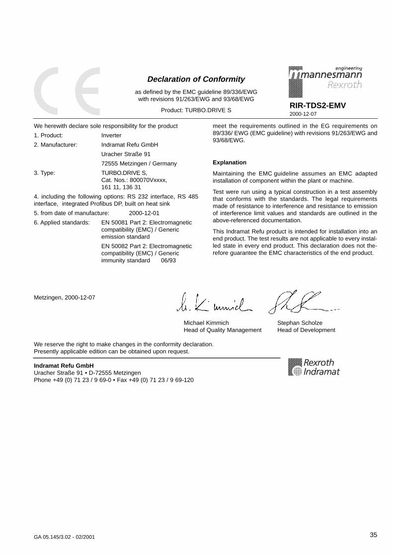
Declaration of Conf ormity
as defined by the EMC guideline 89/336/EWG with revisions 91/263/EWG and 93/68/EWG
Product: TURBO.DRIVE SRIR-TDS2-EMV2000-12-07
meet the requirements outlined in the EG requirements on89/336/ EWG (EMC guideline) with revisions 91/263/EWG and93/68/EWG.
Explanation
Maintaining the EMC guideline assumes an EMC adaptedinstallation of component within the plant or machine.
Test were run using a typical construction in a test assemblythat conforms with the standards. The legal requirementsmade of resistance to interference and resistance to emissionof interference limit values and standards are outlined in theabove-referenced documentation.
This Indramat Refu product is intended for installation into anend product. The test results are not applicable to every instal-led state in every end product. This declaration does not the-refore guarantee the EMC characteristics of the end product.
We herewith declare sole responsibility for the product
1. Product: Inverter
2. Manufacturer: Indramat Refu GmbH
Uracher Straße 91
72555 Metzingen / Germany
3. Type: TURBO.DRIVE S, Cat. Nos.: 800070Vxxxx,161 11, 136 31
4. including the following options: RS 232 interface, RS 485interface, integrated Profibus DP, built on heat sink
5. from date of manufacture: 2000-12-01
6. Applied standards: EN 50081 Part 2: Electromagnetic compatibility (EMC) / Generic emission standard
EN 50082 Part 2: Electromagnetic compatibility (EMC) / Generic immunity standard 06/93
Metzingen, 2000-12-07
Michael Kimmich Stephan ScholzeHead of Quality Management Head of Development
We reserve the right to make changes in the conformity declaration. Presently applicable edition can be obtained upon request.
Indramat Refu GmbHUracher Straße 91 • D-72555 MetzingenPhone +49 (0) 71 23 / 9 69-0 • Fax +49 (0) 71 23 / 9 69-120
36 GA 05.145/3.02 - 02/2001
Declaration of Conf ormity
as per EG Low-Voltage Guidelines 73/23/EWG,Attachment lll B
Product: TURBO.DRIVE SRIR-TDS2-NSR2000-12-07
including the required accessories, as agreeing with EG guide-lines 72/23/EWG, and 93/68/EWG.
Explanation
This product is a component intended for further assembly.Due to the features resulting therefrom, the product cannotinitially meet requirements made of finished products, machi-nes or plants. It must thus be used for mounting/assembly only.
An evaluation of electrical and mechanical safety, environ-mental conditions (e.g., extrinsic objects and/or humidity) mustbe performed after mounting/assembly in the finished product.
The EMC characteristics of this product can change in a moun-ted/ assembled state. An EMC check must thus be made forthe finished product (final unit, machine or plant) by the manu-facturer of the finished unit, machine or plant.
We herewith declare sole responsibility for the product
1. Product: Inverter
2. Manufacturer: Indramat Refu GmbHUracher Straße 9172555 Metzingen / Germany
3. Type: TURBO.DRIVE S, Cat. Nos.: 800070Vxxxx,161 11, 136 31
4. including the following options: RS 232 interface, RS 485interface, integrated Profibus DP, built on heat sink
5. from date of manufacture: 2000-12-01
6. Applicable standard: EN 61010 Part 1: Safety requirements for electrical equipment for measurement, control and laboratory use., 03/94
EN 60204 Part 1: Safety of machinery - Electrical equipment of machines, 06/93
Metzingen, 2000-12-07
Michael Kimmich Stephan ScholzeHead of Quality Management Head of Development
We reserve the right to make changes in the conformity declaration. Presently applicable edition can be obtained upon request.
Indramat Refu GmbHUracher Straße 91 • D-72555 MetzingenPhone +49 (0) 71 23 / 9 69-0 • Fax +49 (0) 71 23 / 9 69-120
37GA 05.145/3.02 - 02/2001
S AM P
L E
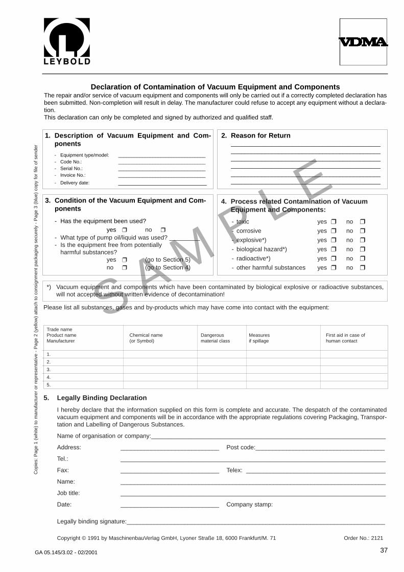
Declaration of Contamination of V acuum Equipment and ComponentsThe repair and/or service of vacuum equipment and components will only be carried out if a correctly completed declaration hasbeen submitted. Non-completion will result in delay. The manufacturer could refuse to accept any equipment without a declara-tion.This declaration can only be completed and signed by authorized and qualified staff.
1. Description of V acuum Equipment and Com-ponents
- Equipment type/model: _________________________________- Code No.: _________________________________- Serial No.: _________________________________- Invoice No.: _________________________________
- Delivery date: __________________________
2. Reason for Return________________________________________________________________________________________________________________________________________________________________________________________________________________________________________________________________________
3. Condition of the V acuum Equipment and Com-ponents
- Has the equipment been used?yes no
- What type of pump oil/liquid was used? _________- Is the equipment free from potentially
harmful substances?yes (go to Section 5)no (go to Section 4)
4. Process related Contamination of V acuum Equipment and Components:
- toxic yes no
- corrosive yes no
- explosive*) yes no
- biological hazard*) yes no
- radioactive*) yes no
- other harmful substances yes no
*) Vacuum equipment and components which have been contaminated by biological explosive or radioactive substances,will not accepted without written evidence of decontamination!
Please list all substances, gases and by-products which may have come into contact with the equipment:
Trade nameProduct name Chemical name Dangerous Measures First aid in case ofManufacturer (or Symbol) material class if spillage human contact
1.
2.
3.
4.
5.
Cop
ies:
Pag
e 1
(whi
te)
to m
anuf
actu
rer
or r
epre
sent
ativ
e -
Pag
e 2
(yel
low
) at
tach
to
cons
ignm
ent
pack
agin
g se
cure
ly -
Pag
e 3
(blu
e) c
opy
for
file
of s
ende
r
5. Legally Binding Declaration
I hereby declare that the information supplied on this form is complete and accurate. The despatch of the contaminatedvacuum equipment and components will be in accordance with the appropriate regulations covering Packaging, Transpor-tation and Labelling of Dangerous Substances.
Name of organisation or company:_____________________________________________________________________
Address: _____________________________ Post code:______________________________________
Tel.: ______________________________________________________________________________
Fax: _____________________________ Telex: _________________________________________
Name: ______________________________________________________________________________
Job title: ______________________________________________________________________________
Date: _____________________________ Company stamp:
Legally binding signature:____________________________________________________________________________
Copyright © 1991 by MaschinenbauVerlag GmbH, Lyoner Straße 18, 6000 Frankfurt/M. 71 Order No.: 2121

LEYBOLD VAKUUM GmbHBonner Strasse 498 (Bayenthal)D-50968 CologneTel.: + 49 221 347-0Fax: + 49 221 347-1250http://www.leyboldvac.dee-mail:[email protected]
AM
CL_
0335
7_20
01
P
G
02.
01P
rinte
d in
Ger
man
y on
chl
orin
e-fre
e b
leac
hed
pap
erTe
chni
cal a
ltera
tions
res
erve
d