Embed Size (px)
Citation preview
TRUE ORTHOPHOTO PRODUCTION USING LIDAR DATA
Arif Günay, Hossein Arefi, Michael Hahn Stuttgart University of Applied Sciences,
Faculty of Geomatics, Computer Science and Mathematics Schellingstr. 24, 70174 Stuttgart, Germany
{guapg111, hossein.arefi, michael.hahn}@hft-stuttgart.de
Key Words: LIDAR, First and last pulse measurement, Orthophoto, True Orthophoto, DTM, DSM
ABSTRACT:
Light Detection and Ranging (LIDAR) has been used for years with a variety of applications, including the efficient creation ofdigital terrain models (DTMs) for large-scale, high-accuracy mapping. LIDAR technology offers fast and detailed collection of 3-Dpoint clouds of the earth surface which can be used for the production of true orthophotos. Research and development is moving quickly towards offering more efficient collection techniques for applications such as city modelling and true orthophoto production.Traditional orthophoto production based on the DTM has to accept that buildings (and any other objects above ground) are not correctly placed in the orthophoto. In principle, true orthophoto generation overcomes these deficiencies by simply taking the digitalsurface model (DSM) into account. However, the resulting true orthophoto often suffers from occluded areas and unsharp edges, inparticular of the orthorectified buildings. By improving the surface modelling more accurate true orthophotos can be produced.
In this paper, true orthophoto generation and options for producing accurate true orthophotos are investigated. (a) In the firstapproach the LIDAR DSM is directly used for generating true orthophotos. (b) In contrast to this method, vector data of buildingsare semi-automatically collected and merged with the DTM to obtain a proper surface representation, which is used as input data for generating true orthophotos in the second approach. The production steps and problems of both procedures for true orthophoto generation are investigated in detail including a comparison of the resulting true orthophotos. For the experimental investigation, a LIDAR data set recorded from downtown Stuttgart is used.
1. INTRODUCTION
The popularity of LIDAR in Photogrammetry and Remote Sensing is constantly increasing as it allows for direct acquisition of three-dimensional (3D) dense information of the earth surface. Extremely dense 3D recordings of point clouds and a very reliably technology are highlights of LIDAR and good reasons for capturing high quality 3D digital surface models using this rather than other systems. LIDAR also provides useful information about objects on the earth surface, which is of particular importance in applications related to urban areas [1]. In practice, for a long time 3D information of the earth surface has been collected by conventional photogrammetric methods. Nowadays, specialised photogram-metric workstations exist but the automated procedures of those workstations generate DSMs and DTMs that are certainly not qualified for true orthophoto production.
Several different approaches have been proposed for 3D building extraction and true orthophoto generation based on LIDAR-DSMs [2], [3]. The dependency on height information, which might be rather arbitrarily sampled 3D points, was critisied by Albertz and Wolf [4] who proposed true orthophoto generation without height information.
In this paper, we deal with automatic and semi automatic true orthophoto production by using LIDAR data and aerial colour images. The objective of this research is to improve the quality of true orthophotos, by investigating efficient and accurate surface modelling. This paper is organized as follows: in the following sections, LIDAR systems, orthophoto and true orthophoto imagery are briefly explained. Chapter 2 describes a proposed algorithm for the investigation. Comparisons of the achieved results are given in Chapter 3.
1.1 LIDAR Systems
LIDAR, also referred to as Airborne Laser Scanning (ALS), is an active remote sensing technique which is basically similar to RADAR but operates at short wavelengths instead of radio waves. LIDAR systems are able to map 3D information about the earth’s surface by scanning the terrain with laser pulses using e.g. an oscillating mirror. The range measurement laser system is part of an integrated system including the Global Positioning System (GPS) and an Inertial Navigation System (INS) [5]. A laser pulse that is fired over vegetation generally has multiple reflections. The most important feature of recent airborne LIDAR systems is its ability to discriminate between first and last pulse reflections. The first laser pulse of the LIDAR system reflects off of the canopy of trees while the last pulse is likely to represent the terrain surface beneath the trees (see fig. 1) [6]. LIDAR also allows providing intensity images (shown in fig. 2) derived from the reflected radiation. Depending on the reflectance properties of the ground surface, of trees and buildings, different grey tones are generated and visualised as intensity images. The completely white areas in Figure 2 represent water surfaces for which no reflected Laser signal could be recorded.
LIDAR can provide precise horizontal and vertical information with a nominal accuracy in the order of 20 to 30 cm in both the vertical direction and, depending on altitude and ground slope conditions, in the horizontal plane [7]. Recent developments in positioning and navigation technology lead to a further increase of the overall accuracy level of the LIDAR scanners [3].
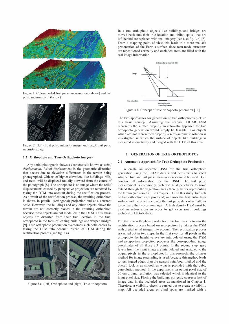
Figure 1: Colour coded first pulse measurement (above) and last pulse measurement (below)
Figure 2: (left) First pulse intensity image and (right) last pulse intensity image
1.2 Orthophoto and True Orthophoto Imagery
Any aerial photograph shows a characteristic known as reliefdisplacement. Relief displacement is the geometric distortion that occurs due to elevation differences in the terrain being photographed. Objects of higher elevation, like buildings, hills, and trees, will be displaced radially outward from the centre of the photograph [8]. The orthophoto is an image where the relief displacements caused by perspective projection are removed by taking the DTM into account during the rectification process. As a result of the rectification process, the resulting orthophoto is shown in parallel (orthogonal) projection and at a constant scale. However, the buildings and any other objects above the terrain are not correctly placed in the resulting orthophoto because these objects are not modelled in the DTM. Thus, these objects are distorted from their true location in the final orthophoto in the form of leaning buildings and warped bridges [9]. True orthophoto production overcomes such deficiencies by taking the DSM into account instead of DTM during the rectification process (see fig. 3.a).
Figure 3.a: (left) Orthophoto and (right) True orthophtoto
In a true orthophoto objects like buildings and bridges are moved back into their true location and “blind spots” that are left behind are replaced with real imagery (see also fig. 3.b) [8]. From a mapping point of view this leads to a more realistic presentation of the Earth’s surface since man-made structures are repositioned correctly and occluded areas are filled with the real image information.
Figure 3.b: Concept of true orthophoto generation [10]
The two approaches for generation of true orthophotos pick up this basic concept. Assuming the scanned LIDAR DSM represents the surface properly an automatic approach for true orthophoto generation would simply be feasible. For objects which are not represented properly a semi-automatic solution is investigated in which the surface of objects like buildings is measured interactively and merged with the DTM of this area.
2. GENERATION OF TRUE ORTHOPHOTOS
2.1 Automatic Approach for True Orthophoto Production
To create an accurate DSM for the true orthophoto generation using the LIDAR data a first decision is to select whether first and last pulse measurements should be used. Both contain 3D information for the DSM. The last pulse measurement is commonly preferred as it penetrates to some extend through the vegetation areas thereby better representing the terrain (see also fig. 1 in Chapter 1.1). In this study, two sets of true orthophotos are produced; one uses the first pulse laser surface and the other one using the last pulse data which allows to compare the two orthoimages. A high density DSM must be used in urban areas in order to get even small buildings included in LIDAR data.
For the true orthophoto production, the first task is to run the rectification process based on reprojection by taking the DSM with digital aerial images into account. The rectification process is carried out in two steps. In the first step, for all pixels in the orthophoto the height values are interpolated using the DSM and perspective projection produces the corresponding image coordinates of all those 3D points. In the second step, grey levels from the input image are interpolated and assigned to the output pixels in the orthophoto. In this research, the bilinear method for image resampling is used, because this method leads to less jagged edges than the nearest neighbour method and the overall look is as smooth as what is provided with the cubic convolution method. In the experiments an output pixel size of 20 cm ground resolution was selected which is identical to the input pixel size. Placing the buildings correctly causes a lack of image data in the occluded areas as mentioned in Chapter 1. Therefore, a visibility check is carried out to create a visibility map. All occluded areas or blind spots are marked with a
specified colour. Orthophotos are created for all images. If the visibility test is not performed during the rectification process, buildings are projected in occluded areas on the terrain as well as on the correct place obtained from the DSM. This effect is known as ghost image (see figure 6). The second step of true orthophoto production is to run a mosaic process in order to fill all occluded areas and merge the overlapping orthophotos in the form of a mosaic. All parts of the occluded areas are filled with corresponding image information which is visible in one of the adjacent orthophotos based on the results of the visibility test. Finally the orthophoto mosaic is created based on seamlines in the overlapping region of the orthophotos. The result of this process is the production of the true orthophoto.
2.2 Semi-Automatic Approach for True Orthophoto Production
In the first approach, a DSM is modelled only from the LIDAR data for true orthophoto production purposes. Even though true orthophoto production is able to overcome deficiencies, such as relief displacement effects, roof borders and ridges of buildings are not represented properly within the LIDAR DSM data.
In order to deal with these shortcomings, a semi automatic approach is used for modelling of a DSM which utilizes not only LIDAR data but also digitized roof borders and building ridges. Firstly, terrain texture is extracted from the LIDAR data instead of the surface texture so that 3D points of buildings and trees are removed. Then, footprints of removed objects are filled with a regular grid based on the specified density parameter (in this case 2m) during production of a DTM. In the next step, roof borders and ridges are digitized using a photogrammetric stereo workstation and superimposed on the DTM to make the DSM (see also fig. 4).
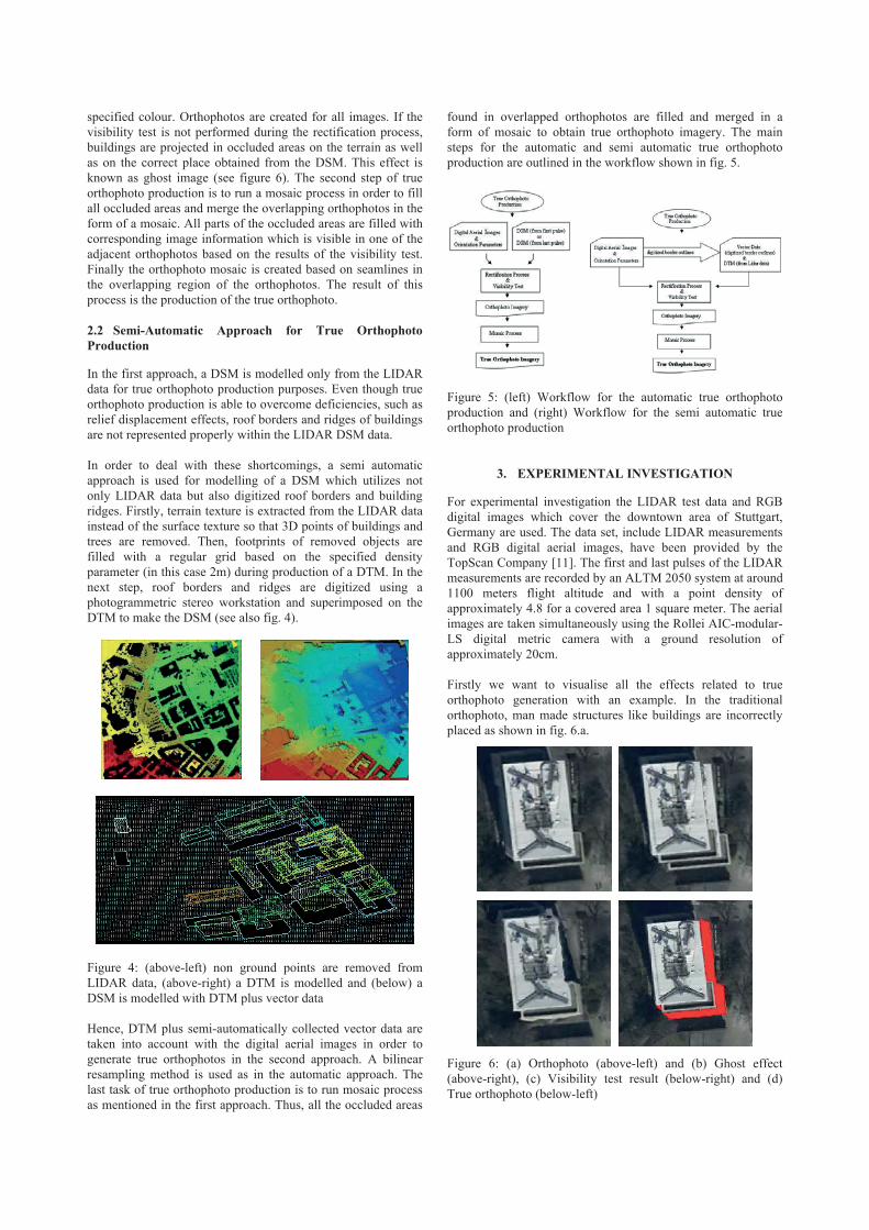
Figure 4: (above-left) non ground points are removed from LIDAR data, (above-right) a DTM is modelled and (below) a DSM is modelled with DTM plus vector data
Hence, DTM plus semi-automatically collected vector data are taken into account with the digital aerial images in order to generate true orthophotos in the second approach. A bilinear resampling method is used as in the automatic approach. The last task of true orthophoto production is to run mosaic process as mentioned in the first approach. Thus, all the occluded areas
found in overlapped orthophotos are filled and merged in a form of mosaic to obtain true orthophoto imagery. The main steps for the automatic and semi automatic true orthophoto production are outlined in the workflow shown in fig. 5.
Figure 5: (left) Workflow for the automatic true orthophoto production and (right) Workflow for the semi automatic true orthophoto production
3. EXPERIMENTAL INVESTIGATION
For experimental investigation the LIDAR test data and RGB digital images which cover the downtown area of Stuttgart, Germany are used. The data set, include LIDAR measurements and RGB digital aerial images, have been provided by the TopScan Company [11]. The first and last pulses of the LIDAR measurements are recorded by an ALTM 2050 system at around 1100 meters flight altitude and with a point density of approximately 4.8 for a covered area 1 square meter. The aerial images are taken simultaneously using the Rollei AIC-modular-LS digital metric camera with a ground resolution of approximately 20cm.
Firstly we want to visualise all the effects related to true orthophoto generation with an example. In the traditional orthophoto, man made structures like buildings are incorrectly placed as shown in fig. 6.a.
Figure 6: (a) Orthophoto (above-left) and (b) Ghost effect (above-right), (c) Visibility test result (below-right) and (d) True orthophoto (below-left)
To eliminate the relief displacement effects of buildings the LIDAR DSM is taken into account during the rectification process. If the rectification process runs without the visibility test, a ghost effect occurs (see also fig 6.b). For this reason, a visibility test is executed simultaneously during the rectification process to locate occluded areas. Hereby, all occluded areas were marked in colour and the ghost effect was removed in the resulting orthophoto (see fig 6.c). After all processes, the building is correctly placed at its true locations and the occluded areas are filled with proper image information in the resulting true orthophoto (see also fig. 6.d). On the other hand, fig 6.d also shows that the borders of the building are not represented with a realistic shape; even those that are correctly repositioned in the true orthophoto.
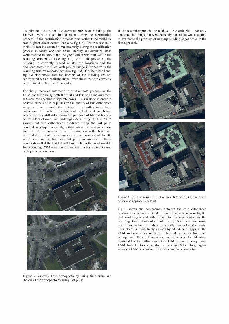
For the purpose of automatic true orthophoto production, the DSM produced using both the first and last pulse measurement is taken into account in separate cases. This is done in order to observe affects of laser pulses on the quality of true orthophoto imagery. Even though the obtained true orthophotos have overcome the relief displacement effect and occlusion problems, they still suffer from the presence of blurred borders on the edges of roads and buildings (see also fig 7). Fig. 7 also shows that true orthophotos produced using the last pulse resulted in sharper road edges than when the first pulse was used. These differences in the resulting true orthophotos are most likely caused by differences in the presence of the 3D information in the first and last pulse measurement. These results show that the last LIDAR laser pulse is the most suitable for producing DSM which in turn means it is best suited for true orthophoto production.
Figure 7: (above) True orthophoto by using first pulse and (below) True orthophoto by using last pulse
In the second approach, the achieved true orthophoto not only contained buildings that were correctly placed but was also able to overcome the problem of unsharp building edges noted in the first approach.
Figure 8: (a) The result of first approach (above), (b) the result of second approach (below)
Fig 8 shows the comparison between the true orthophoto produced using both methods. It can be clearly seen in fig 8.b that roof edges and ridges are sharply represented in the resulting true orthophoto while in fig 8.a there are some distortions on the roof edges, especially those of nested roofs. This effect is most likely caused by blunders or gaps in the DSM so these areas are seen as blurred in the resulting true orthophoto. These deficiencies are overcome by blendingdigitized border outlines into the DTM instead of only using DSM from LIDAR (see also fig. 9.a and 9.b). Thus, higher accuracy DSM is achieved for true orthophoto production.
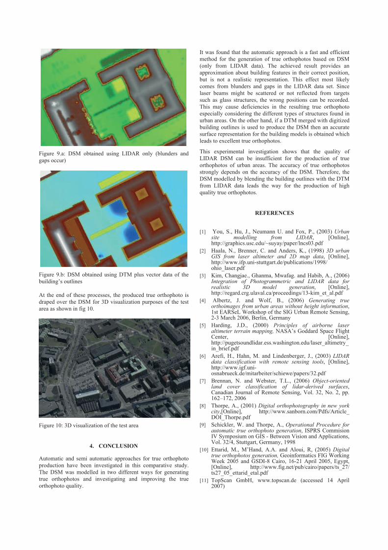
Figure 9.a: DSM obtained using LIDAR only (blunders and gaps occur)
Figure 9.b: DSM obtained using DTM plus vector data of the building’s outlines
At the end of these processes, the produced true orthophoto is draped over the DSM for 3D visualization purposes of the test area as shown in fig 10.
Figure 10: 3D visualization of the test area
4. CONCLUSION
Automatic and semi automatic approaches for true orthophoto production have been investigated in this comparative study. The DSM was modelled in two different ways for generating true orthophotos and investigating and improving the true orthophoto quality.
It was found that the automatic approach is a fast and efficient method for the generation of true orthophotos based on DSM (only from LIDAR data). The achieved result provides an approximation about building features in their correct position, but is not a realistic representation. This effect most likely comes from blunders and gaps in the LIDAR data set. Since laser beams might be scattered or not reflected from targets such as glass structures, the wrong positions can be recorded. This may cause deficiencies in the resulting true orthophoto especially considering the different types of structures found in urban areas. On the other hand, if a DTM merged with digitized building outlines is used to produce the DSM then an accurate surface representation for the building models is obtained which leads to excellent true orthophotos.
This experimental investigation shows that the quality of LIDAR DSM can be insufficient for the production of true orthophotos of urban areas. The accuracy of true orthophotos strongly depends on the accuracy of the DSM. Therefore, the DSM modelled by blending the building outlines with the DTM from LIDAR data leads the way for the production of high quality true orthophotos.
REFERENCES
[1] You, S., Hu, J., Neumann U. and Fox, P., (2003) Urbansite modelling from LIDAR, [Online], http://graphics.usc.edu/~suyay/paper/lncs03.pdf
[2] Haala, N., Brenner, C. and Anders, K., (1998) 3D urban GIS from laser altimeter and 2D map data, [Online], http://www.ifp.uni-stuttgart.de/publications/1998/ohio_laser.pdf
[3] Kim, Changjae., Ghanma, Mwafag. and Habib, A., (2006) Integration of Photogrammetric and LIDAR data for realistic 3D model generation, [Online], http://regard.crg.ulaval.ca/proceedings/13-kim_et_al.pdf
[4] Albertz, J. and Wolf, B., (2006) Generating true orthoimages from urban areas without height information,1st EARSeL Workshop of the SIG Urban Remote Sensing, 2-3 March 2006, Berlin, Germany
[5] Harding, J.D., (2000) Principles of airborne laser altimeter terrain mapping, NASA’s Goddard Space Flight Center, [Online], http://pugetsoundlidar.ess.washington.edu/laser_altimetry_in_brief.pdf
[6] Arefi, H., Hahn, M. and Lindenberger, J., (2003) LIDARdata classification with remote sensing tools, [Online], http://www.igf.uni-osnabrueck.de/mitarbeiter/schiewe/papers/32.pdf
[7] Brennan, N. and Webster, T.L., (2006) Object-orientedland cover classification of lidar-derived surfaces,Canadian Journal of Remote Sensing, Vol. 32, No. 2, pp. 162–172, 2006
[8] Thorpe, A., (2001) Digital orthophotography in new york city,[Online], http://www.sanborn.com/Pdfs/Article_ DOI_Thorpe.pdf
[9] Schickler, W. and Thorpe, A., Operational Procedure for automatic true orthophoto generation, ISPRS Commision IV Symposium on GIS - Between Vision and Applications, Vol. 32/4, Stuttgart, Germany, 1998
[10] Ettarid, M., M’Hand, A.A. and Aloui, R, (2005) Digitaltrue orthophotos generation, Geoinformatics FIG Working Week 2005 and GSDI-8 Cairo, 16-21 April 2005, Egypt, [Online], http://www.fig.net/pub/cairo/papers/ts_27/ ts27_05_ettarid_etal.pdf
[11] TopScan GmbH, www.topscan.de (accessed 14 April 2007)