Embed Size (px)
Citation preview

TS 22 – New Development and Applications for Imagery Håkon Andresen TS22.7 Efficient and Well-documented Digital Orthophoto Production from Airborne Photogrammetry 3rd FIG Regional Conference Jakarta, Indonesia, October 3-7, 2004
1/13
Efficient and Well-documented Digital Orthophoto Production from Airborne Photogrammetry
Håkon ANDRESEN, Norway/Indonesia
Key words: Digital Terrain Models, 3D city models, conventional orthophotos, true orthophotos, orthophoto quality measures. SUMMARY Digital orthophotos offer a valuable level of detail in their coexistence with accurate vector data. Large and medium scale airborne photogrammetry typically leads to orthophoto ground sample distances in the range 0.10 – 0.40 meter, thus offering a better level of detail than the commercial satellite products that have entered the marketplace over the last few years. The usage of orthophotos together with 3D city models is becoming popular in conjunction with modern urban mapping. With all buildings in the 3D model registered in their exact position with both planar and height coordinates, the generation of orthophotos with vertical buildings and hidden areas filled in from adjoining images becomes possible. The generation of such geometrically correct (“TRUE”) orthophotos differs significantly from conventional orthophoto projects with stricter requirements to the digital terrain -and building models and with the need for sophisticated visibility analysis implemented in the orthophoto routine. BlomInfo A/S and PT. Blom Nusantara use this methodology to describe urban topography in very precise, cost-efficient and highly illustrative manners.

TS 22 – New Development and Applications for Imagery Håkon Andresen TS22.7 Efficient and Well-documented Digital Orthophoto Production from Airborne Photogrammetry 3rd FIG Regional Conference Jakarta, Indonesia, October 3-7, 2004
2/13
Efficient and Well-documented Digital Orthophoto Production from Airborne Photogrammetry
Håkon ANDRESEN, Norway/Indonesia
1. INTRODUCTION Orthophoto production concerns the process of transforming the central projection of the terrain as recorded in aerial photos into a digital geo-referenced image (orthophoto) with the same geometric attributes as a map. This transformation from a central projection into an orthogonal projection requires a Digital Terrain Model (DTM) with sufficient density and accuracy. The complexity of digital orthophoto production depends on a number of different project characteristics and varies from fairly straightforward processes to more complex and time-consuming workflows. The required positional accuracy and the resolution of the orthophoto pixels on the ground are two of the most dominant orthophoto project characteristics. Orthophoto projects are usually delivered to the end user as a seamless mosaic of orthophoto map-sheets in which all seam-lines (edges) between the individual orthophotos have been made invisible. If building structures are to be placed at their exact geometric position in the orthophotos, this requires all 3D structures to be included in the DTM and to be carefully analyzed and processed by the orthophoto generation software. Normally, orthophotos produced from a DTM on the ground are referred to as orthophotos and the more advanced version with geometrically correct building structures are referred to as “TRUE” orthophotos. 2. ORTHOPHOTO PROJECT BREAKDOWN Orthophoto projects have a lot in common with any other airborne photogrammetric mapping project. The flight-mission, recording of digital source image material and procedures for establishing accurate Exterior Orientation are therefore not described in this paper. However, it is underlined that these procedures will have a direct impact on the geometric accuracy of the produced orthophoto. After an acceptable Exterior Orientation has been established, a typical orthophoto project can be divided into the following chronological procedures:
TS 22 – New Development and Applications for Imagery Håkon Andresen TS22.7 Efficient and Well-documented Digital Orthophoto Production from Airborne Photogrammetry 3rd FIG Regional Conference Jakarta, Indonesia, October 3-7, 2004
3/13
Fig. 1 a.
Area definition: Definition of overlapping orthophoto generation shapes from the center of the individual aerial source images. The overlapping areas are important because these are the areas where the invisible seam-lines (edges) between the individually generated orthophotos will have to be located.
Fig. 1 b.
DTM preparation: All areas where orthophotos are to be generated must be covered by a DTM with sufficient density and accuracy. These terrain data are usually derived from one or a combination of the following methods: -Manual stereo registrations, usually in a combination of grid and breaklines. -Automatic measurements (correlation). -Contour lines from older topographic maps (usually supported by other terrain features). -Laser scanning.
Fig. 1 c.
Orthophoto generation: Generation of orthophotos followed by possible correction of DTM errors, removal of image dust and radiometric (color) adjustments. Projects not flown directly East-West or North-South will usually result in many background pixels in the generated orthophotos. Different software handles this challenge differently, but in general it is advised to fly orthophoto projects in a direction close to East-West or North-South.

TS 22 – New Development and Applications for Imagery Håkon Andresen TS22.7 Efficient and Well-documented Digital Orthophoto Production from Airborne Photogrammetry 3rd FIG Regional Conference Jakarta, Indonesia, October 3-7, 2004
4/13
Fig. 1 d.
Mosaicing: Seam-lines (edges) have to be generated and processed in the overlap areas between the individually generated orthophotos. If the seam-lines are saved in a vector file, this is usually helpful for making sure that they are indeed invisible in the final orthophoto mosaic.
Fig. 1 e.
Tiling into map-sheets and delivery: Orthophotos are usually delivered as individual orthophoto map-sheets with the geo-referencing information in either the image file header or in a “sister” text-file. Depending on the size of the total project area and the specified orthophoto ground resolution, sophisticated compression formats such as ECW and MrSID often make it possible to deliver larger project areas in one single image-file. The delivery is usually made on CD-ROM, DVD or on external hard-drives.
3. DTM IMPLEMENTATION AND ORTHOPHOTO ACCURACY The geometric accuracy of any produced orthophoto is directly linked to the quality of the DTM. Inaccurate DTM data is the most dominant source of error in the produced orthophotos and the workload required to establish a satisfactory DTM is, of course, very dependent on the topography in the project area. As stated in the previous section, the DTM is usually derived from one or a combination of the following methods: − Manual stereo registrations, usually in a combination of grid and breaklines. − Automatic measurements (correlation). − Contour lines from older topographic maps (usually supported by other terrain features). − Laser scanning.

TS 22 – New Development and Applications for Imagery Håkon Andresen TS22.7 Efficient and Well-documented Digital Orthophoto Production from Airborne Photogrammetry 3rd FIG Regional Conference Jakarta, Indonesia, October 3-7, 2004
5/13
Objects elevated a distance (dH) above the DTM will be pictured a radial distance (dR) outwards from the center of the image as given by the formula: dR = ( r/c ) · dH where r is the distance from the center of the image and c is the focal length. The same formula can be used to calculate positional errors (dR) in the orthophoto caused by errors in the DTM (dH).
Fig. 2: Radial displacement (dR) for an object elevated above the terrain surface.
Different software offers many different methods and routines for dynamic filtering, quality improvement and accuracy documentation of the DTM. One way to document the DTM accuracy is to measure a statistically sufficient number of random points on the terrain in the photogrammetric stereo models and compare these height-coordinates with corresponding interpolated height values in the DTM. Statistics can then be calculated and documented as suggested in figure 3 a. and 3 b. Note that as long as both the DTM registrations and the control measurements are made from the same imagery with the same Exterior Orientation, these control measurements do not express the final accuracy of the DTM in the terrain.
Fig. 3 a: Reported statistics for height differences between control measurements made on the ground in the photogrammetric stereo models and corresponding height values interpolated in the DTM. (Example from project photographed in 1:12000 image scale with normal-angle camera, c = 0,303 m).

TS 22 – New Development and Applications for Imagery Håkon Andresen TS22.7 Efficient and Well-documented Digital Orthophoto Production from Airborne Photogrammetry 3rd FIG Regional Conference Jakarta, Indonesia, October 3-7, 2004
6/13
Fig. 3 b: Graphical illustration of the 214 control measurements in figure 3 a. The average height difference of minus 0,222 meter (“H interpolated in the DTM” minus “H measured”) means that on average this DTM lies 0,222 meter below the 214 control measurements.
4. CONVENTIONAL ORTHOPHOTOS In combination with accurate vector data, orthophotos facilitate the interpretation and analysis of the map data. Color orthophotos are typically preferred to grayscale orthophotos as colors help increase these advantages. However, grayscale orthophotos will often be a good option on projects where budget limitations and other project parameters suggest a grayscale approach.
Fig. 4 a: Only vector data (“top” view). Fig. 4 b: 24-bit color orthophoto, 0.10 m GSD.

TS 22 – New Development and Applications for Imagery Håkon Andresen TS22.7 Efficient and Well-documented Digital Orthophoto Production from Airborne Photogrammetry 3rd FIG Regional Conference Jakarta, Indonesia, October 3-7, 2004
7/13
Fig. 4 c: Combined 24-bit color orthophoto pixels and vector data (“top” view). (Danish TK3 / TK99 mapping standard).
Fig. 5: 8-bit grayscale orthophoto, 0.20 m GSD. (Norwegian SOSI mapping standard). Large and medium scale airborne photogrammetry typically leads to orthophoto ground sample distances (GSD) in the range 0.10 – 0.40 meter and most orthophoto production lines handles grayscale, color and infrared imagery.

TS 22 – New Development and Applications for Imagery Håkon Andresen TS22.7 Efficient and Well-documented Digital Orthophoto Production from Airborne Photogrammetry 3rd FIG Regional Conference Jakarta, Indonesia, October 3-7, 2004
8/13
Fig. 6: 24-bit color orthophoto, 0.10 m GSD. Fig. 7: Infrared orthophoto, 0.50 m GSD. Because conventional orthophotos are generated from DTMs representing the terrain and do not include buildings and other features above this DTM surface, such 3D objects are not pictured at their exact geometric position. Thus, the geometric accuracy of conventional orthophotos must be checked up against features on the ground. Because the radial distortion increases with the distance to the image center, orthophotos are normally generated from the center of each aerial source image. Note that this differs from the photogrammetric stereo registration where the stereo overlap between the aerial photos must be the area unit. 5. 3D CITY MODELLING AND TRUE ORTHOPHOTOS 3D city models have become popular in conjunction with modern urban mapping. These digital terrain models very precisely describe urban topography and can, for example, be used for urban planning, telecom applications, environmental analysis, risk management, transportation logistics and visualization of proposed developments.
Fig. 8 a: 3D City Model, Copenhagen. (BlomInfo A/S - Denmark).

TS 22 – New Development and Applications for Imagery Håkon Andresen TS22.7 Efficient and Well-documented Digital Orthophoto Production from Airborne Photogrammetry 3rd FIG Regional Conference Jakarta, Indonesia, October 3-7, 2004
9/13
Fig. 8 b: Screen-dump from a 7 minutes fly through simulation in Copenhagen. (BlomInfo A/S - Denmark).
Fig. 8 c: Screen-dump from a 5 minutes fly through simulation in Copenhagen. (BlomInfo A/S - Denmark). Generation of geometrically correct “TRUE” orthophotos with vertical buildings and hidden areas filled in from adjoining images can be divided into two major work tasks. First, all 3D objects have to be included in the DTM. This operation usually combines a Digital Terrain Model (DTM) on the ground with a Digital Building Model (DBM) to form a Digital Surface Model (DSM). Principally, this DSM can also be a product from other methods such as very dense automatic correlated measurements or airborne laser scanning, but manual photogrammetric registrations currently seem to have an advantage in the way they represent the exact shape of the building structures. Secondly, generation of geometrically correct “TRUE” orthophotos requires sophisticated visibility analysis implemented in the orthophoto routine so that hidden areas can be filled in from other neighboring images. Figure 9 a. and 9 b. illustrate different relief displacements

TS 22 – New Development and Applications for Imagery Håkon Andresen TS22.7 Efficient and Well-documented Digital Orthophoto Production from Airborne Photogrammetry 3rd FIG Regional Conference Jakarta, Indonesia, October 3-7, 2004
10/13
and different hidden areas due to different perspective center positions. In the visibility analysis, the hidden areas are identified and orthophoto pixels for these areas are generated and inserted from adjoining source imagery. Color balancing and seam-line feathering are important routines in these processes.
Fig. 9 a: Hidden areas from different perspective centers. (Morten Nielsen).
Fig. 9 b: Common area (yellow) from 4 different perspective centers. 60% image overlap both forward and sideways. (Morten Nielsen).
Fig. 10 a: Conventional orthophoto from DTM on the ground (“top” view).
Fig. 10 b: Building structure included in DTM/DBM to form a DSM (“isometric” view).
Fig. 10 c: Orthophoto with correct vertical roof and indicated hidden area (in blue) to be filled from adjoining images (“top” view). Note that this screendump was made before ortho-pixels were automatically generated and inserted from an adjoining image.
Figure 10 a. – 10 c. illustrate the difference between a conventional orthophoto from a DTM on the ground and a “TRUE” orthophoto before orthophoto pixels are automatically generated and inserted into the calculated hidden area from a suitable neighboring image.
TS 22 – New Development and Applications for Imagery Håkon Andresen TS22.7 Efficient and Well-documented Digital Orthophoto Production from Airborne Photogrammetry 3rd FIG Regional Conference Jakarta, Indonesia, October 3-7, 2004
11/13
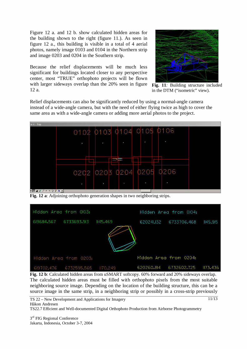
Figure 12 a. and 12 b. show calculated hidden areas for the building shown to the right (figure 11.). As seen in figure 12 a., this building is visible in a total of 4 aerial photos, namely image 0103 and 0104 in the Northern strip and image 0203 and 0204 in the Southern strip. Because the relief displacements will be much less significant for buildings located closer to any perspective center, most “TRUE” orthophoto projects will be flown with larger sideways overlap than the 20% seen in figure 12 a.
Fig. 11: Building structure included in the DTM (“isometric” view).
Relief displacements can also be significantly reduced by using a normal-angle camera instead of a wide-angle camera, but with the need of either flying twice as high to cover the same area as with a wide-angle camera or adding more aerial photos to the project.
Fig. 12 a: Adjoining orthophoto generation shapes in two neighboring strips.
Fig. 12 b: Calculated hidden areas from uSMART softcopy. 60% forward and 20% sideways overlap. The calculated hidden areas must be filled with orthophoto pixels from the most suitable neighboring source image. Depending on the location of the building structure, this can be a source image in the same strip, in a neighboring strip or possibly in a cross-strip previously

TS 22 – New Development and Applications for Imagery Håkon Andresen TS22.7 Efficient and Well-documented Digital Orthophoto Production from Airborne Photogrammetry 3rd FIG Regional Conference Jakarta, Indonesia, October 3-7, 2004
12/13
used for minimizing the ground control in the Aerial Triangulation component of the photogrammetric mapping project.
Fig. 13: Conventional orthophoto (left) and “TRUE” orthophoto (right), both overlaid with the same vector map of the building outlines. (Morten Nielsen). Figure 13. illustrates the significant advantage of “TRUE” orthophotos in built up areas. The conventional orthophoto has a good fit with objects in level with the terrain, but not with the building structures that were not included in the DTM used for the ortho-rectification. This effect has been eliminated in the “TRUE” orthophoto. 6. SUMMARIZING REMARKS It is expected that there will be a continuous and increasing demand for both conventional and “TRUE” orthophotos. What will be the most cost-efficient option of these two products will vary depending on different project characteristics and end-user demands. If there is a requirement that all 3D building structures are to be placed at their exact geometric position, the “TRUE” orthophoto workflow requires that the orthophotos must be generated in more complex manners with the introduction of more time consuming processes in both the establishment of the DTM and in the orthophoto rectification process. Both conventional orthophoto production and “TRUE” orthophoto production are highly automated processes and the cost difference between the two products is highly related to the level of automatization. A current and great challenge is to make the “TRUE” orthophoto production as automatic as possible and thereby minimize the cost difference between these two products.

TS 22 – New Development and Applications for Imagery Håkon Andresen TS22.7 Efficient and Well-documented Digital Orthophoto Production from Airborne Photogrammetry 3rd FIG Regional Conference Jakarta, Indonesia, October 3-7, 2004
13/13
The establishment of a Digital Building Model (DBM) and a Digital Surface Model (DSM) that include all 3D structures in the project area is by far the most labor-intensive part of a “TRUE” orthophoto project. If these models already exist, this significantly lowers the threshold for a “TRUE” orthophoto approach. If the orthophoto is to be draped over a 3D city model, only “TRUE” orthophotos will have a perfect fit onto the 3D building model. For both production lines, it is important that automatic procedures are closely combined and integrated with manual quality control and satisfactory documentation routines. REFERENCES Blankenberg, L.E., (1998) Produksjon av digitale ortofoto – Prinsipper og metoder. Nielsen, M., (2004) True orthophoto generation. Technical University of Denmark –
Informatics and Mathematical Modelling. BIOGRAPHICAL NOTES Hakon Andresen graduated from the Department of Mapping Sciences at The Norwegian Agricultural University in 1999. His experience includes studies at the University of Calgary (Canada), two years with Blom in Abu Dhabi (United Arab Emirates) and he is at present Production Manager in PT. Blom Nusantara in Bandung (Indonesia). CONTACT Håkon Andresen PT. Blom Nusantara Jl. Cicendo No 18 - 3rd Floor Bandung 40117 INDONESIA. Tel. + 62 22 42 19 800, + 62 8 1220 99663 Fax + 62 22 42 35 645 Email: [email protected]