Embed Size (px)
Citation preview
Treball Final de Grau
Tutor/s
Dr. Manel Vicente Buil Departament Enginyeria Química
Dra. Esther Chamarro Aguilera Departament Enginyeria Química
Design of an industrial process for the Diacetone--Fructose (DAF) production.
Disseny d’un procés industrial de producción de Diacetona-
Fructosa (DAF).
Noelia González Arias June 2016


Aquesta obra esta subjecta a la llicència de: Reconeixement–NoComercial-SenseObraDerivada
http://creativecommons.org/licenses/by-nc-nd/3.0/es/

Voldria agrair aquest treball principalment als meus tutors, el Dr. Manel Vicente i la Dra.
Esther Chamarro, pel seu ajut i dedicació, des del primer dia fins l’últim.
Agrair també a la meva família el donar-me ànims i ajudar-me sempre a veure el got mig ple.
Donar gràcies especialment al meu germà Carlos, per fer-me companyia a les llargues nits de
treball.
De nou, a tots, moltes gràcies.


REPORT

Design of an industrial process for the Diacetone-β-Fructose (DAF) production 1
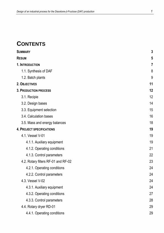
CONTENTS
SUMMARY....................................................................................................................................... 3
RESUM ........................................................................................................................................... 5
1. INTRODUCTION ............................................................................................................................ 7
1.1. Synthesis of DAF .............................................................................................................. 8
1.2. Batch plants ...................................................................................................................... 9
2. OBJECTIVES ............................................................................................................................. 11
3. PRODUCTION PROCESS ............................................................................................................. 12
3.1. Recipie ............................................................................................................................ 12
3.2. Design bases .................................................................................................................. 14
3.3. Equipment selection ....................................................................................................... 15
3.4. Calculation bases ........................................................................................................... 16
3.5. Mass and energy balances ............................................................................................. 18
4. PROJECT SPECIFICATIONS ......................................................................................................... 19
4.1. Vessel V-01 .................................................................................................................... 19
4.1.1. Auxiliary equipment ................................................................................................ 19
4.1.2. Operating conditions .............................................................................................. 21
4.1.3. Control parameters................................................................................................. 22
4.2. Rotary filters RF-01 and RF-02 ...................................................................................... 23
4.2.1. Operating conditions .............................................................................................. 24
4.2.2. Control parameters................................................................................................. 24
4.3. Vessel V-02 .................................................................................................................... 24
4.3.1. Auxiliary equipment ................................................................................................ 24
4.3.2. Operating conditions .............................................................................................. 27
4.3.3. Control parameters................................................................................................. 28
4.4. Rotary dryer RD-01 ........................................................................................................ 29
4.4.1. Operating conditions .............................................................................................. 29
2 González Arias, Noelia
4.4.2. Control parameters ................................................................................................. 30
4.5. Connectivity and automation .......................................................................................... 30
5. RESIDUE MANAGEMENT ............................................................................................................. 32
6. SCHEDULING ............................................................................................................................. 33
6.1. General considerations ................................................................................................... 33
6.2. Batch time ....................................................................................................................... 33
6.3. Production capacity ........................................................................................................ 35
6.3.1. Production in non-overlapping campaign ............................................................... 35
6.3.2. Production in overlapping campaign ...................................................................... 36
7. PRODUCTION PLANNING ............................................................................................................. 38
8. FINANCIAL VIABILITY .................................................................................................................. 41
8.1. Estimation of the initial investment ................................................................................. 41
8.2. Cost of goods sold .......................................................................................................... 41
8.3. Profit & Losses Statement (P&L) .................................................................................... 45
8.4. Net Present Value, Discounted Pay Back and Internal Rate Return .............................. 46
9. CONCLUSIONS........................................................................................................................... 50
10. REFERENCES AND NOTES ........................................................................................................ 53
11. ACRONYMS ............................................................................................................................. 55
12. NOMENCLATURE ..................................................................................................................... 56
13. INDEX OF FIGURES AND TABLES ................................................................................................ 56
APPENDICES
APPENDIX 1: SAFETY DATA SHEETS ............................................................................................... 63
APPENDIX 2: MATERIAL BALANCE .................................................................................................. 73
APPENDIX 3: MANUAL OF CALCULUS .............................................................................................. 74
APPENDIX 4: SPECIFICATION SHEETS ............................................................................................. 93
Design of an industrial process for the Diacetone-β-Fructose (DAF) production 3
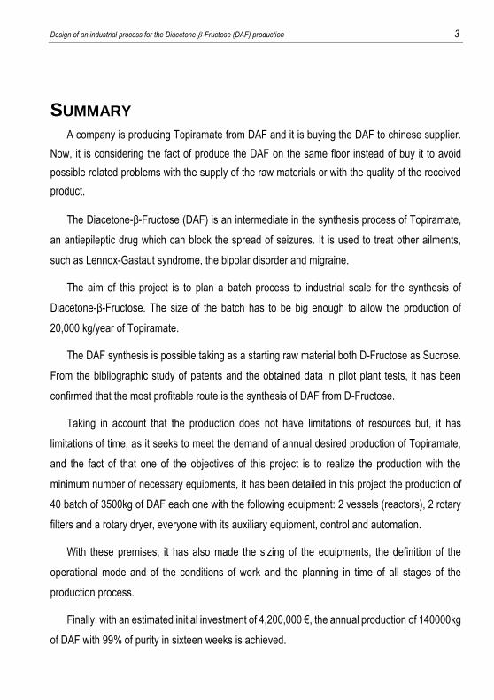
SUMMARY
A company is producing Topiramate from DAF and it is buying the DAF to chinese supplier.
Now, it is considering the fact of produce the DAF on the same floor instead of buy it to avoid
possible related problems with the supply of the raw materials or with the quality of the received
product.
The Diacetone-β-Fructose (DAF) is an intermediate in the synthesis process of Topiramate,
an antiepileptic drug which can block the spread of seizures. It is used to treat other ailments,
such as Lennox-Gastaut syndrome, the bipolar disorder and migraine.
The aim of this project is to plan a batch process to industrial scale for the synthesis of
Diacetone-β-Fructose. The size of the batch has to be big enough to allow the production of
20,000 kg/year of Topiramate.
The DAF synthesis is possible taking as a starting raw material both D-Fructose as Sucrose.
From the bibliographic study of patents and the obtained data in pilot plant tests, it has been
confirmed that the most profitable route is the synthesis of DAF from D-Fructose.
Taking in account that the production does not have limitations of resources but, it has
limitations of time, as it seeks to meet the demand of annual desired production of Topiramate,
and the fact of that one of the objectives of this project is to realize the production with the
minimum number of necessary equipments, it has been detailed in this project the production of
40 batch of 3500kg of DAF each one with the following equipment: 2 vessels (reactors), 2 rotary
filters and a rotary dryer, everyone with its auxiliary equipment, control and automation.
With these premises, it has also made the sizing of the equipments, the definition of the
operational mode and of the conditions of work and the planning in time of all stages of the
production process.
Finally, with an estimated initial investment of 4,200,000 €, the annual production of 140000kg
of DAF with 99% of purity in sixteen weeks is achieved.

Design of an industrial process for the Diacetone-β-Fructose (DAF) production 5
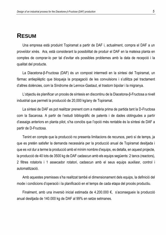
RESUM
Una empresa està produint Topiramat a partir de DAF i, actualment, compra el DAF a un
proveïdor xinès. Ara, està considerant la possibilitat de produir el DAF en la mateixa planta en
comptes de comprar-lo per tal d’evitar els possibles problemes amb la data de recepció i la
qualitat del producte.
La Diacetona-β-Fructosa (DAF) és un compost intermedi en la síntesi del Topiramat, un
fàrmac antiepilèptic que bloqueja la propagació de les convulsions i s’utilitza pel tractament
d’altres dolències, com la Síndrome de Lennox-Gastaut, el trastorn bipolar i la migranya.
L’objectiu és planificar un procés de síntesis en discontinu de la Diacetona-β-Fructosa a nivell
industrial que permeti la producció de 20,000 kg/any de Topiramat.
La síntesi de DAF es pot realitzar prenent com a matèria prima de partida tant la D-Fructosa
com la Sacarosa. A partir de l’estudi bibliogràfic de patents i de dades obtingudes a partir
d’assaigs anteriors en planta pilot, s’ha conclòs que l’opció més rentable és la síntesi de DAF a
partir de D-Fructosa.
Tenint en compte que la producció no presenta limitacions de recursos, però sí de temps, ja
que es pretén satisfer la demanda necessària per la producció anual de Topiramat desitjada i
que es vol dur a terme la producció amb el mínim nombre d’equips, es detalla, en aquest projecte,
la producció de 40 lots de 3500 kg de DAF cadascun amb els equips següents: 2 tancs (reactors),
2 filtres rotatoris i 1 assecador rotatori, cadascun amb el seus equips auxiliasr, control i
automatització.
Amb aquestes premisses s’ha realitzat també el dimensionament dels equips, la definició del
mode i condicions d’operació i la planificació en el temps de cada etapa del procés productiu.
Finalment, amb una inversió inicial estimada de 4.200.000 €, s’aconsegueix la producció
anual desitjada de 140.000 kg de DAF al 99% en setze setmanes.

Design of an industrial process for the Diacetone-β-Fructose (DAF) production 7
1. INTRODUCTION
Topiramate is an anticonvulsant drug endowed of a broad spectrum antiepileptic activity.
It is used clinically as monotherapy in partial seizures, for treatment of seizures associated
with Lennox-Gastaut syndrome in children over 2 years and how migraine treatment after ruling
out other possible alternatives(1).
In 2010, Topiramate becomes a generic active ingredient and, as a result, many market
studies are performed to assess the possibility of their synthesis and marketing. Following this
study, existence of a potential market for Topiramate in Europe, USA and South America was
discovered and, from that moment, many projects emerge that were aimed at obtaining a
synthesis route of Topiramate.
Work Final Year: Producción del Topiramato: Elección de la vía de síntesis y estudios en
planta piloto(2) is based on them. It contains a bibliographic review about process in question,
obtained results in various pilot plant testing and the discussion about possible alternatives to
carry out the synthesis.
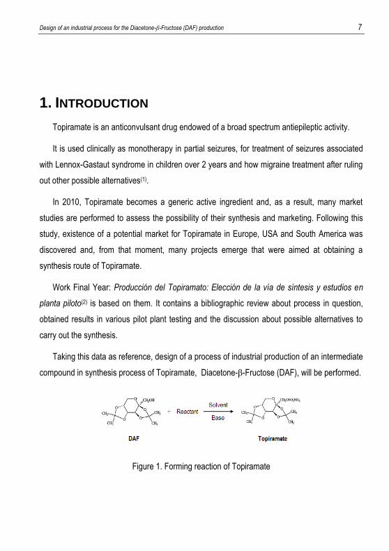
Taking this data as reference, design of a process of industrial production of an intermediate
compound in synthesis process of Topiramate, Diacetone-β-Fructose (DAF), will be performed.
Figure 1. Forming reaction of Topiramate
8 González Arias, Noelia
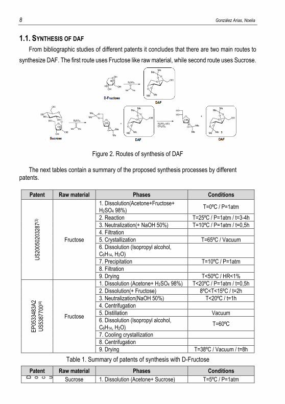
1.1. SYNTHESIS OF DAF
From bibliographic studies of different patents it concludes that there are two main routes to
synthesize DAF. The first route uses Fructose like raw material, while second route uses Sucrose.
Figure 2. Routes of synthesis of DAF
The next tables contain a summary of the proposed synthesis processes by different patents.
Patent Raw material Phases Conditions
US
2005
0203
287(3
)
Fructose
1. Dissolution(Acetone+Fructose+ H2SO4 98%)
T=0ºC / P=1atm
2. Reaction T=25ºC / P=1atm / t=3-4h
3. Neutralization(+ NaOH 50%) T=10ºC / P=1atm / t=0,5h
4. Filtration
5. Crystallization T=65ºC / Vacuum
6. Dissolution (Isopropyl alcohol, C6H14, H2O)
7. Precipitation T=10ºC / P=1atm
8. Filtration
9. Drying T<50ºC / HR<1%
EP
0533
483A
2
US
5387
700(4
)
Fructose
1. Dissolution (Acetone+ H2SO4 98%) T<20ºC / P=1atm / t=0,5h
2. Dissolution(+ Fructose) 8ºC<T<15ºC / t=2h
3. Neutralization(NaOH 50%) T<20ºC / t=1h
4. Centrifugation
5. Distillation Vacuum
6. Dissolution (Isopropyl alcohol, C6H14, H2O)
T=60ºC
7. Cooling crystallization
8. Centrifugation
9. Drying T=38ºC / Vacuum / t=8h
Table 1. Summary of patents of synthesis with D-Fructose
Patent Raw material Phases Conditions
D o c u m e n t o f U n i v e r s i t y o f R i o d e J a n e i r o ( 5 ) Sucrose 1. Dissolution (Acetone+ Sucrose) T=5ºC / P=1atm
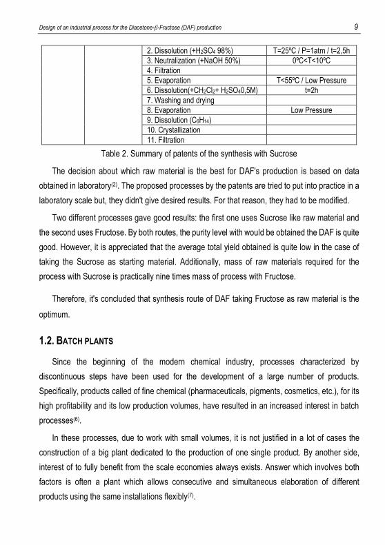
Design of an industrial process for the Diacetone-β-Fructose (DAF) production 9
2. Dissolution (+H2SO4 98%) T=25ºC / P=1atm / t=2,5h
3. Neutralization (+NaOH 50%) 0ºC<T<10ºC
4. Filtration
5. Evaporation T<55ºC / Low Pressure
6. Dissolution(+CH2Cl2+ H2SO40,5M) t=2h
7. Washing and drying
8. Evaporation Low Pressure
9. Dissolution (C6H14)
10. Crystallization
11. Filtration
Table 2. Summary of patents of the synthesis with Sucrose
The decision about which raw material is the best for DAF's production is based on data
obtained in laboratory(2). The proposed processes by the patents are tried to put into practice in a
laboratory scale but, they didn't give desired results. For that reason, they had to be modified.
Two different processes gave good results: the first one uses Sucrose like raw material and
the second uses Fructose. By both routes, the purity level with would be obtained the DAF is quite
good. However, it is appreciated that the average total yield obtained is quite low in the case of
taking the Sucrose as starting material. Additionally, mass of raw materials required for the
process with Sucrose is practically nine times mass of process with Fructose.
Therefore, it's concluded that synthesis route of DAF taking Fructose as raw material is the
optimum.
1.2. BATCH PLANTS
Since the beginning of the modern chemical industry, processes characterized by
discontinuous steps have been used for the development of a large number of products.
Specifically, products called of fine chemical (pharmaceuticals, pigments, cosmetics, etc.), for its
high profitability and its low production volumes, have resulted in an increased interest in batch
processes(6).
In these processes, due to work with small volumes, it is not justified in a lot of cases the
construction of a big plant dedicated to the production of one single product. By another side,
interest of to fully benefit from the scale economies always exists. Answer which involves both
factors is often a plant which allows consecutive and simultaneous elaboration of different
products using the same installations flexibly(7).
10 González Arias, Noelia
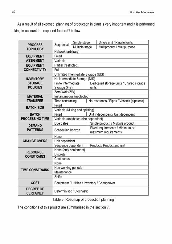
As a result of all exposed, planning of production in plant is very important and it is performed
taking in account the exposed factors(8) bellow.
PROCESS TOPOLOGY
Sequential Single stage Single unit / Parallel units
Multiple stage Multiproduct / Multipurpose
Network (arbitrary)
EQUIPMENT ASSIGMENT
Fixed
Variable
EQUIPMENT CONNECTIVITY
Partial (restricted)
Full
INVENTORY STORAGE POLICIES
Unlimited Intermediate Storage (UIS)
No intermediate Storage (NIS)
Finite Intermediate Storage (FIS)
Dedicated storage units / Shared storage units
Zero Wait (ZW)
MATERIAL TRANSFER
Instantaneous (neglected)
Time consuming No-resources / Pipes / Vessels (pipeless)
BATCH SIZE Fixed
Variable (Mixing and splitting)
BATCH PROCESSING TIME
Fixed Unit independent / Unit dependent
Variable (unit/batch-size dependent)
DEMAND PATTERNS
Due dates Single product / Multiple product
Scheduling horizon Fixed requirements / Minimum or maximum requirements
CHANGE OVERS
None
Unit dependent
Sequence dependent Product / Product and unit
RESOURCE CONSTRAINS
None (only equipment)
Discrete
Continuous
TIME CONSTRAINS
None
Non-working periods
Maintenance
Shifts
COST Equipment / Utilities / Inventory / Changeover
DEGREE OF CERTAINLY
Deterministic / Stochastic
Table 3. Roadmap of production planning
The conditions of this project are summarized in the section 7.
Design of an industrial process for the Diacetone-β-Fructose (DAF) production 11
2. OBJECTIVES
A company is producing Topiramate from DAF and it considers the fact of produce the DAF
on the same floor instead of buy it.
Purpose of this project has been to design a production process of DAF that allows answering
to the demands of the production of 20 annual lots of 1000 kg each of Topiramate. For it, more
concrete aims have been fixed:
To select the necessary equipments for the annual production of 40 batch of DAF
of 3500 kg each one, taking as premise that the number of equipments must be
minimum.
To select batch size of DAF and to realize sizing of involved equipments in the
process.
To determine necessary time for production of one batch of DAF and to plan
production of the annual demanded quantity.
To value the economic viability of the project by means of the calculation of Present
Value (NPV), Discounted Payback and Internal Rate of Return.
12 González Arias, Noelia
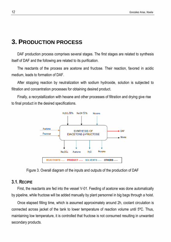
3. PRODUCTION PROCESS
DAF production process comprises several stages. The first stages are related to synthesis
itself of DAF and the following are related to its purification.
The reactants of the process are acetone and fructose. Their reaction, favored in acidic
medium, leads to formation of DAF.
After stopping reaction by neutralization with sodium hydroxide, solution is subjected to
filtration and concentration processes for obtaining desired product.
Finally, a recrystallization with hexane and other processes of filtration and drying give rise
to final product in the desired specifications.
Figure 3. Overall diagram of the inputs and outputs of the production of DAF
3.1. RECIPIE
First, the reactants are fed into the vessel V-01. Feeding of acetone was done automatically
by pipeline, while fructose will be added manually by plant personnel in big bags through a hoist.
Once elapsed filling time, which is assumed approximately around 2h, coolant circulation is
connected across jacket of the tank to lower temperature of reaction volume until 5ºC. Thus,
maintaining low temperature, it is controlled that fructose is not consumed resulting in unwanted
secondary products.
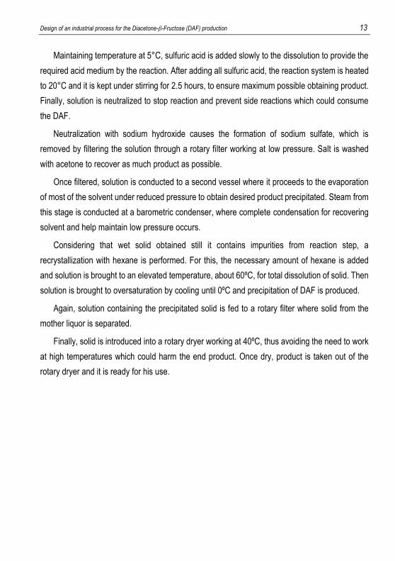
Design of an industrial process for the Diacetone-β-Fructose (DAF) production 13
Maintaining temperature at 5°C, sulfuric acid is added slowly to the dissolution to provide the
required acid medium by the reaction. After adding all sulfuric acid, the reaction system is heated
to 20°C and it is kept under stirring for 2.5 hours, to ensure maximum possible obtaining product.
Finally, solution is neutralized to stop reaction and prevent side reactions which could consume
the DAF.
Neutralization with sodium hydroxide causes the formation of sodium sulfate, which is
removed by filtering the solution through a rotary filter working at low pressure. Salt is washed
with acetone to recover as much product as possible.
Once filtered, solution is conducted to a second vessel where it proceeds to the evaporation
of most of the solvent under reduced pressure to obtain desired product precipitated. Steam from
this stage is conducted at a barometric condenser, where complete condensation for recovering
solvent and help maintain low pressure occurs.
Considering that wet solid obtained still it contains impurities from reaction step, a
recrystallization with hexane is performed. For this, the necessary amount of hexane is added
and solution is brought to an elevated temperature, about 60ºC, for total dissolution of solid. Then
solution is brought to oversaturation by cooling until 0ºC and precipitation of DAF is produced.
Again, solution containing the precipitated solid is fed to a rotary filter where solid from the
mother liquor is separated.
Finally, solid is introduced into a rotary dryer working at 40ºC, thus avoiding the need to work
at high temperatures which could harm the end product. Once dry, product is taken out of the
rotary dryer and it is ready for his use.
14 González Arias, Noelia
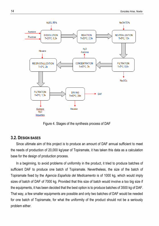
Figure 4. Stages of the synthesis process of DAF
3.2. DESIGN BASES
Since ultimate aim of this project is to produce an amount of DAF annual sufficient to meet
the needs of production of 20,000 kg/year of Topiramate, it has taken this data as a calculation
base for the design of production process.
In a beginning, to avoid problems of uniformity in the product, it tried to produce batches of
sufficient DAF to produce one batch of Topiramate. Nevertheless, the size of the batch of
Topiramate fixed by the Agencia Española del Medicamento is of 1000 kg, which would imply
sizes of batch of DAF of 7000 kg. Provided that this size of batch would involve a too big size if
the equipments, it has been decided that the best option is to produce batches of 3500 kg of DAF.
That way, a few smaller equipments are possible and only two batches of DAF would be needed
for one batch of Topiramate, for what the uniformity of the product should not be a seriously
problem either.
Design of an industrial process for the Diacetone-β-Fructose (DAF) production 15
As for mode of operation, it will work in batch, because for this type of production volumes is
common practice in the pharmaceutical industry to work in batch since the plants are usually
multipurpose.
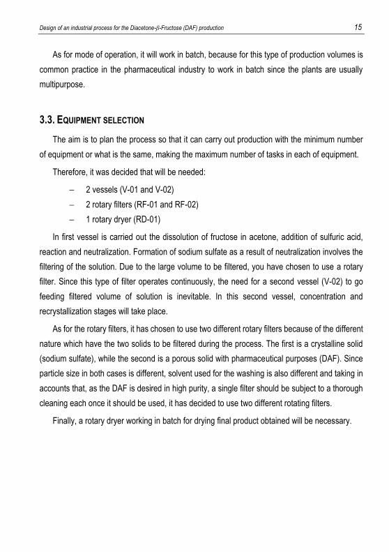
3.3. EQUIPMENT SELECTION
The aim is to plan the process so that it can carry out production with the minimum number
of equipment or what is the same, making the maximum number of tasks in each of equipment.
Therefore, it was decided that will be needed:
2 vessels (V-01 and V-02)
2 rotary filters (RF-01 and RF-02)
1 rotary dryer (RD-01)
In first vessel is carried out the dissolution of fructose in acetone, addition of sulfuric acid,
reaction and neutralization. Formation of sodium sulfate as a result of neutralization involves the
filtering of the solution. Due to the large volume to be filtered, you have chosen to use a rotary
filter. Since this type of filter operates continuously, the need for a second vessel (V-02) to go
feeding filtered volume of solution is inevitable. In this second vessel, concentration and
recrystallization stages will take place.
As for the rotary filters, it has chosen to use two different rotary filters because of the different
nature which have the two solids to be filtered during the process. The first is a crystalline solid
(sodium sulfate), while the second is a porous solid with pharmaceutical purposes (DAF). Since
particle size in both cases is different, solvent used for the washing is also different and taking in
accounts that, as the DAF is desired in high purity, a single filter should be subject to a thorough
cleaning each once it should be used, it has decided to use two different rotating filters.
Finally, a rotary dryer working in batch for drying final product obtained will be necessary.
16 González Arias, Noelia
Figure 5. Distribution of the tasks on the equipments
3.4. CALCULATION BASES
For the correct sizing of the necessary equipments for production process design, it has made
the material and energy balances in the system. For its resolution, the application of a set of
assumptions has been necessary, which are shown below.
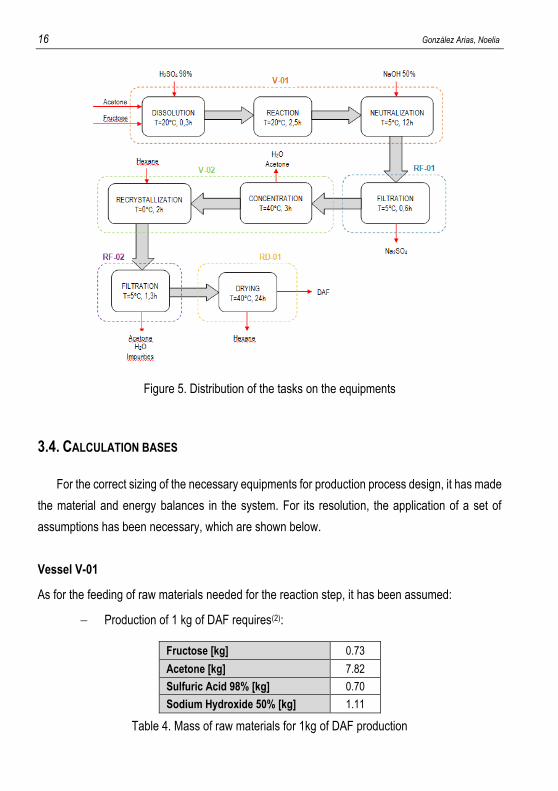
Vessel V-01
As for the feeding of raw materials needed for the reaction step, it has been assumed:
Production of 1 kg of DAF requires(2):
Fructose [kg] 0.73
Acetone [kg] 7.82
Sulfuric Acid 98% [kg] 0.70
Sodium Hydroxide 50% [kg] 1.11
Table 4. Mass of raw materials for 1kg of DAF production
Design of an industrial process for the Diacetone-β-Fructose (DAF) production 17
Yield of DAF forming reaction is about 97%.
In reference to energy balances:
Dissolution of sulfuric acid in acetone is exothermically and enthalpy of dissolution
is similar to that would correspond if the solvent was water.
The above assumption is also applied to sodium hydroxide dissolution.
During the stages of heating and cooling, heat transfer is the limiting step of the
stage.
Rotary filters RF-01 and RF-02
The simplifications applied in filtration steps and on which is based sizing of the filters, are the
following:
Filters work under vacuum and are able to retain 100% of solid present in solution.
For washing the solid that is to be removed, it is necessary a mass of solvent
equivalent to 20 wt% of filtered solid. In addition, since washing occurs at a low
temperature of the solvent, the calculation is simplified by assuming negligible loss
of solid by dissolution.
During washing, get yourself thoroughly wash filtered solid, which leaves filter
moistened with a solvent content of 15 kg/kg of dry solid.
Vessel V-02
In vessel V-02, stages of concentration and recrystallization of DAF occur. The assumptions
made are:
After concentration step, the solid obtained inside tank contains about 15 kg solvent
/ kg of dry solid.
As acetone is more volatile than water, it has been assumed that condensate
consists of 90% acetone and 10% water.
Again, according to the data obtained in the pilot plant, it has been supposed the
need 2.64 kg of hexane / kg DAF recovered at the end of the process.
In reference to energy balances, again it is assumed that the transfer stage is the limiting
stage.
18 González Arias, Noelia
Rotary dryer RD-01
In case of rotary dryer, it has been taken the psychrometric data(9) of the system hexane-
nitrogen as an approximation to the reality of the system hexane-air. In addition, it is known that
drying rate of a solid has constant and variable periods that depend on solid and solvent but, has
only used the period of constant speed to obtain guidance on drying time.
3.5. MASS AND ENERGY BALANCES
Based on these assumptions, the material and energy balances have been solved and it has
been possible to get composition and temperature of system in each point of production process
of a batch.
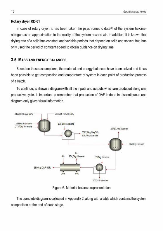
To continue, is shown a diagram with all the inputs and outputs which are produced along one
productive cycle. Is important to remember that production of DAF is done in discontinuous and
diagram only gives visual information.
Figure 6. Material balance representation
The complete diagram is collected in Appendix 2, along with a table which contains the system
composition at the end of each stage.
Design of an industrial process for the Diacetone-β-Fructose (DAF) production 19
4. PROJECT SPECIFICATIONS
In this chapter, it will be detailed the specifications of the above mentioned equipments. It will
be talked about their size, materials and their auxiliary equipments if they are required.
In addition, it will be talked too about the connections between equipments, automation and
control parameters, without to deepen too.
4.1. VESSEL V-01
In the vessel V-01, the next stages take place: feeding of raw materials, dissolution, reaction
and neutralization.
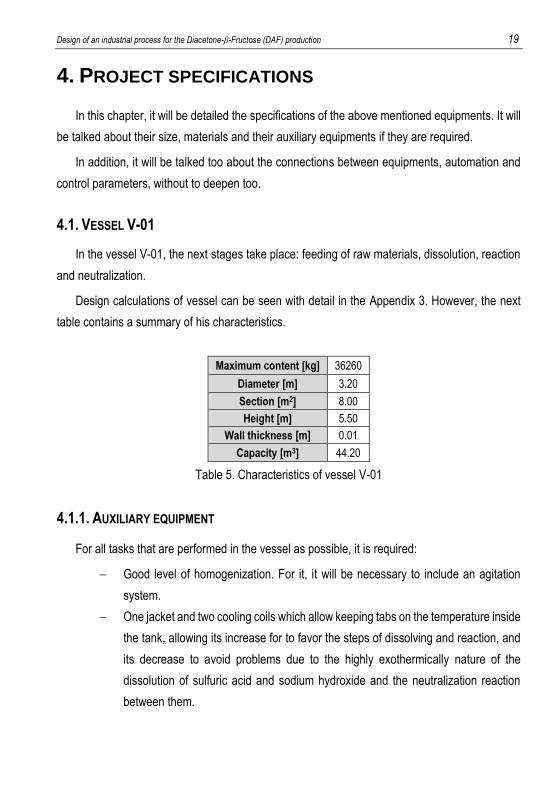
Design calculations of vessel can be seen with detail in the Appendix 3. However, the next
table contains a summary of his characteristics.
Maximum content [kg] 36260
Diameter [m] 3.20
Section [m2] 8.00
Height [m] 5.50
Wall thickness [m] 0.01
Capacity [m3] 44.20
Table 5. Characteristics of vessel V-01
4.1.1. AUXILIARY EQUIPMENT
For all tasks that are performed in the vessel as possible, it is required:
Good level of homogenization. For it, it will be necessary to include an agitation
system.
One jacket and two cooling coils which allow keeping tabs on the temperature inside
the tank, allowing its increase for to favor the steps of dissolving and reaction, and
its decrease to avoid problems due to the highly exothermically nature of the
dissolution of sulfuric acid and sodium hydroxide and the neutralization reaction
between them.
20 González Arias, Noelia
Agitation system
Due to the large volumes with which it works and the presence of solids in the solution which
can accumulate in the bottom of the vessel, it has opted for the use of a double agitator which
consists an anchor stirrer, to prevent accumulation, and a blades stirrer at half height to ensure
good homogenization.
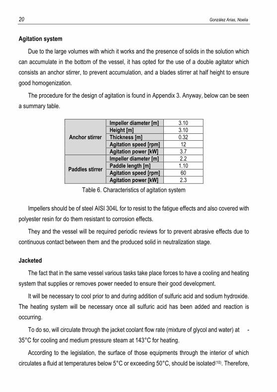
The procedure for the design of agitation is found in Appendix 3. Anyway, below can be seen
a summary table.
Anchor stirrer
Impeller diameter [m] 3.10
Height [m] 3.10
Thickness [m] 0.32
Agitation speed [rpm] 12
Agitation power [kW] 3.7
Paddles stirrer
Impeller diameter [m] 2.2
Paddle length [m] 1.10
Agitation speed [rpm] 60
Agitation power [kW] 2.3
Table 6. Characteristics of agitation system
Impellers should be of steel AISI 304L for to resist to the fatigue effects and also covered with
polyester resin for do them resistant to corrosion effects.
They and the vessel will be required periodic reviews for to prevent abrasive effects due to
continuous contact between them and the produced solid in neutralization stage.
Jacketed
The fact that in the same vessel various tasks take place forces to have a cooling and heating
system that supplies or removes power needed to ensure their good development.
It will be necessary to cool prior to and during addition of sulfuric acid and sodium hydroxide.
The heating system will be necessary once all sulfuric acid has been added and reaction is
occurring.
To do so, will circulate through the jacket coolant flow rate (mixture of glycol and water) at -
35°C for cooling and medium pressure steam at 143°C for heating.
According to the legislation, the surface of those equipments through the interior of which
circulates a fluid at temperatures below 5°C or exceeding 50°C, should be isolated(10). Therefore,
Design of an industrial process for the Diacetone-β-Fructose (DAF) production 21
the outside of the jacketed with glass wool of 70 mm thick, which is considered the minimum
required for industrial equipment will be covered.
Coils
As already said before, the dissolution of sulfuric acid is highly exothermically, but still the
temperature can be controlled only through coolant circulating through jacketed.
Not so in the case of addition of sodium hydroxide. Its dissolution releases energy, and so
does its reaction with sulfuric acid that there is in the middle. Consequentially, controlling
temperature only through circulation of coolant through the jacketed is not possible.
Therefore, it was considered necessary to include two coils with approximately the following
characteristics:
Internal diameter of the tube [m] 2.55
External diameter of the tube [m] 1.65
Diameter of a round [m] 0.50
Number of rounds 90
Length [m] 11.70
Height [m] 4.50
Table 7. Characteristics of coils
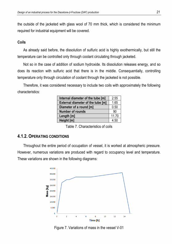
4.1.2. OPERATING CONDITIONS
Throughout the entire period of occupation of vessel, it is worked at atmospheric pressure.
However, numerous variations are produced with regard to occupancy level and temperature.
These variations are shown in the following diagrams:
Figure 7. Variations of mass in the vessel V-01
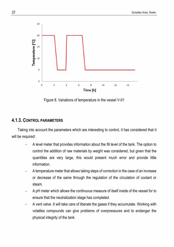
22 González Arias, Noelia
Figure 8. Variations of temperature in the vessel V-01
4.1.3. CONTROL PARAMETERS
Taking into account the parameters which are interesting to control, it has considered that it
will be required:
A level meter that provides information about the fill level of the tank. The option to
control the addition of raw materials by weight was considered, but given that the
quantities are very large, this would present much error and provide little
information.
A temperature meter that allows taking steps of correction in the case of an increase
or decrease of the same through the regulation of the circulation of coolant or
steam.
A pH meter which allows the continuous measure of itself inside of the vessel for to
ensure that the neutralization stage has completed.
A vent valve. It will take care of liberate the gases if they accumulate. Working with
volatiles compounds can give problems of overpressures and to endanger the
physical integrity of the tank.
Design of an industrial process for the Diacetone-β-Fructose (DAF) production 23
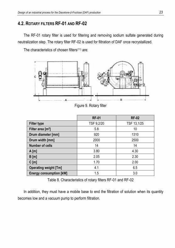
4.2. ROTARY FILTERS RF-01 AND RF-02
The RF-01 rotary filter is used for filtering and removing sodium sulfate generated during
neutralization step. The rotary filter RF-02 is used for filtration of DAF once recrystallized.
The characteristics of chosen filters(11) are:
Figure 9. Rotary filter
RF-01 RF-02
Filter type TSF 9,2/20 TSF 13,1/25
Filter area [m2] 5.8 10
Drum diameter [mm] 920 1310
Drum width [mm] 2000 2500
Number of cells 14 14
A [m] 3.80 4.30
B [m] 2.05 2.30
C [m] 1.70 2.00
Operating weight [Tm] 4.1 6.5
Energy consumption [kW] 1.5 3.0
Table 8. Characteristics of rotary filters RF-01 and RF-02
In addition, they must have a mobile base to end the filtration of solution when its quantity
becomes low and a vacuum pump to perform filtration.
24 González Arias, Noelia
4.2.1. OPERATING CONDITIONS
Based on heuristics(12)(13), it was been decided to work with two rotary filters in the next
conditions:
RF-01 RF-02
Turning speed [rpm] 0.33 0.33
Pressure difference [Pa] 6,772.76 – 20,318.27 60,954.82 – 84,659.47
Angle submerged [rad] 2.20 2.20
Table 9. Operating conditions of rotary filters
In these conditions, again basing on heuristics, achieving the next filtration speeds is possible:
1221 kg/(h·m2) for Na2SO4 and 305 kg/(h·m2) for DAF.
4.2.2. CONTROL PARAMETERS
The most important parameter to consider in control is pressure, because suction generated
from inside rotary drum is what causes the filtration. As the process progresses, filters are
obstructing, so that filtration is increasingly less effective, requiring a regulation of pressure for an
increase in suction.
In filtration step of DAF, however, it is important to control temperature of the washing solvent,
to minimize product loss by dissolution.
4.3. VESSEL V-02
The mother liquor from the rotary filter RF-01 is fed to vessel V-02, where concentration step
and recrystallizing of DAF take place. The V-02 is made of steel AISI 304L and presents the same
characteristics, in terms of dimensions, that the vessel V-01
4.3.1. AUXILIARY EQUIPMENT
The stages that are developed inside of the vessel V-02 imply the need for a good agitation
system and a system that allows regulation of temperature. They require too the installation of a
Design of an industrial process for the Diacetone-β-Fructose (DAF) production 25
barometric condenser in which liquefy the vapors from the concentration step and which allows
maintaining the low pressure inside the vessel.
Furthermore, since the barometric condenser can maintain low pressure but does not
generate it, an ejector will also be necessary. This will be responsible for the launch of stage and
removing non-condensable gases capacitor which can enter to the unit. One demister will also be
added for retaining dragged liquid droplets by the gases.
Finally, it will be necessary also a tank for storage of the condensed from barometric
condenser, which ensures the submersion of lower part of the barometric column.
Jacketed and agitation system
The Vessel V-02 has got the same agitation system, jacketed and insulating of the V-01. The
only difference between the vessels will be that blade stirrer will not work while the liquid inside
thetank is not enough to cover it, so only the anchor stirrer will provide the agitation. In this case,
it is sacrificed the efficiency of agitation in benefit of possibility of using tank for different purposes.
Similarly, the coolant and steam are the same that supply the vessel V-01.
Barometric condenser
In barometric condenser is pretended to recover the vapor of solvent, which cannot be
liberated to the atmosphere, and use it for filling the barometric column.
The vapor arrives to condenser in its boiling point at working pressure. It is pretended to
condense it at 38ºC for avoid its evaporation. It is decided to use a Cooltrans solution of glycol in
water at 60%(14), since it is the coolant which supplies all the installation and it can work at very
low temperatures.
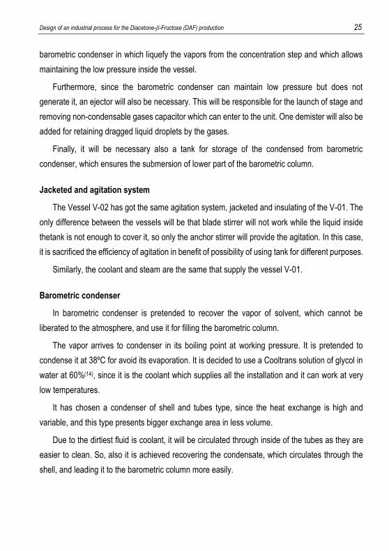
It has chosen a condenser of shell and tubes type, since the heat exchange is high and
variable, and this type presents bigger exchange area in less volume.
Due to the dirtiest fluid is coolant, it will be circulated through inside of the tubes as they are
easier to clean. So, also it is achieved recovering the condensate, which circulates through the
shell, and leading it to the barometric column more easily.
26 González Arias, Noelia
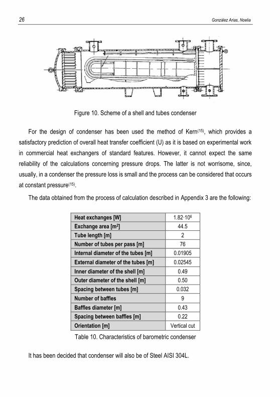
Figure 10. Scheme of a shell and tubes condenser
For the design of condenser has been used the method of Kern(15), which provides a
satisfactory prediction of overall heat transfer coefficient (U) as it is based on experimental work
in commercial heat exchangers of standard features. However, it cannot expect the same
reliability of the calculations concerning pressure drops. The latter is not worrisome, since,
usually, in a condenser the pressure loss is small and the process can be considered that occurs
at constant pressure(15).
The data obtained from the process of calculation described in Appendix 3 are the following:
Heat exchanges [W] 1.82·106
Exchange area [m2] 44.5
Tube length [m] 2
Number of tubes per pass [m] 76
Internal diameter of the tubes [m] 0.01905
External diameter of the tubes [m] 0.02545
Inner diameter of the shell [m] 0.49
Outer diameter of the shell [m] 0.50
Spacing between tubes [m] 0.032
Number of baffles 9
Baffles diameter [m] 0.43
Spacing between baffles [m] 0.22
Orientation [m] Vertical cut
Table 10. Characteristics of barometric condenser
It has been decided that condenser will also be of Steel AISI 304L.
Design of an industrial process for the Diacetone-β-Fructose (DAF) production 27
Barometric column
Barometric column is coupled to the output of the heat exchanger. Here, condensate is
introduced and discharged in a well at room temperature. This temperature difference will cause
the liquid to flow by gravity through the column by maintaining the hydrostatic pressure between
the internal pressure and atmospheric pressure.
It is considered that the output speed of the acetone-water mixture able to keep the vacuum
inside of the unit is 0.98 m/s(16). Through appropriate calculations ( Appendix 3) are obtained the
needed characteristics of the column: 0,065 m of inner diameter and 6.4m of height.
4.3.2. OPERATING CONDITIONS
As discussed previously, in the vessel V-02 take place numerous steps involving continuous
changes in operating conditions.
The vessel V-02 works at atmospheric pressure except during concentration step of DAF, in
which a pressure drop is generated to facilitate solvent evaporation.
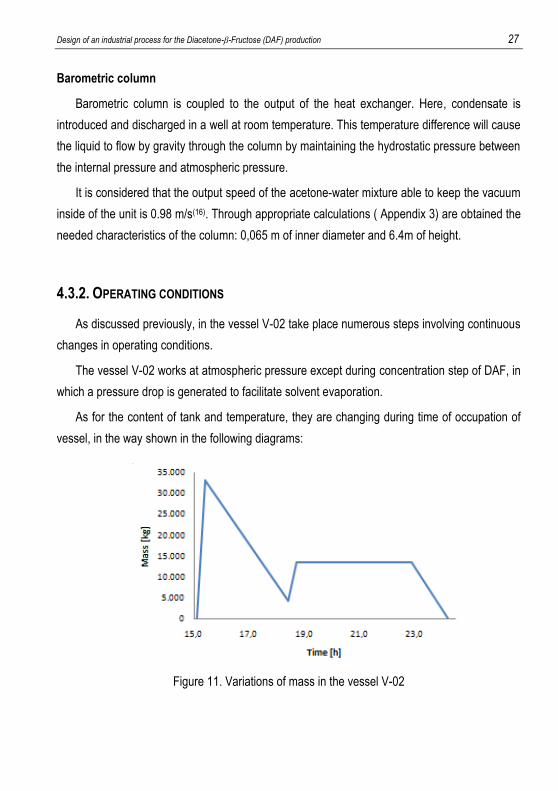
As for the content of tank and temperature, they are changing during time of occupation of
vessel, in the way shown in the following diagrams:
Figure 11. Variations of mass in the vessel V-02
28 González Arias, Noelia
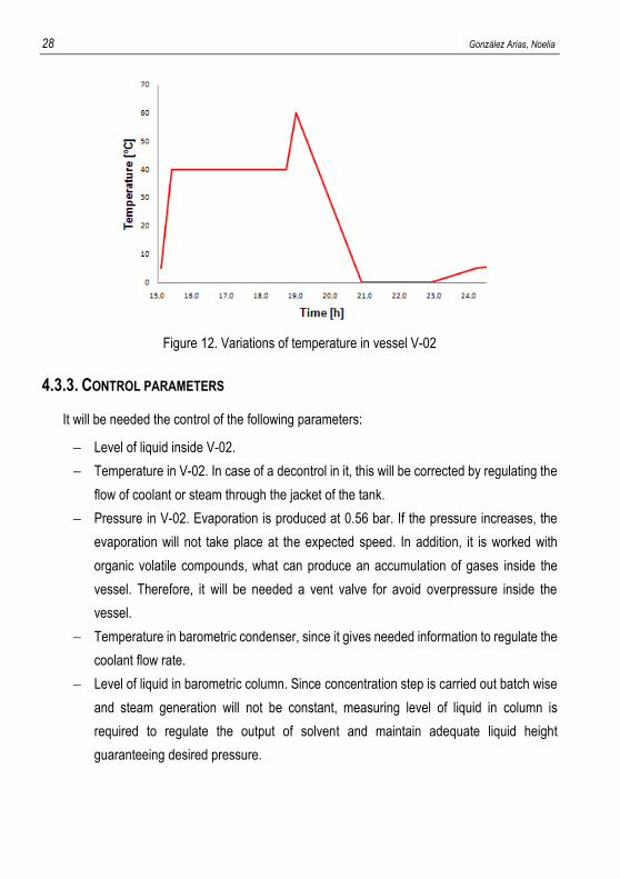
Figure 12. Variations of temperature in vessel V-02
4.3.3. CONTROL PARAMETERS
It will be needed the control of the following parameters:
Level of liquid inside V-02.
Temperature in V-02. In case of a decontrol in it, this will be corrected by regulating the
flow of coolant or steam through the jacket of the tank.
Pressure in V-02. Evaporation is produced at 0.56 bar. If the pressure increases, the
evaporation will not take place at the expected speed. In addition, it is worked with
organic volatile compounds, what can produce an accumulation of gases inside the
vessel. Therefore, it will be needed a vent valve for avoid overpressure inside the
vessel.
Temperature in barometric condenser, since it gives needed information to regulate the
coolant flow rate.
Level of liquid in barometric column. Since concentration step is carried out batch wise
and steam generation will not be constant, measuring level of liquid in column is
required to regulate the output of solvent and maintain adequate liquid height
guaranteeing desired pressure.
Design of an industrial process for the Diacetone-β-Fructose (DAF) production 29
4.4. ROTARY DRYER RD-01
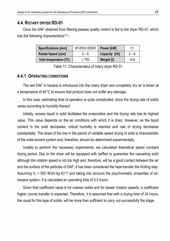
Once the DAF obtained from filtering passes quality control is fed to the dryer RD-01, which
has the following characteristics(17):
Specifications [mm] Փ1200x120000 Power [kW] 11
Rotate Speed [rpm] 3 – 8 Capacity [t/h] 2 – 6
Inlet temperature [ºC] ≤ 700 Weight [t] 14.8
Table 11. Characteristics of rotary dryer RD-01
4.4.1. OPERATING CONDITIONS
The wet DAF in hexane is introduced into the rotary dryer and completely dry air is blown at
a temperature of 40°C to ensure that product does not suffer any damage.
In this case, estimating time of operation is quite complicated, since the drying rate of solids
varies according to humidity thereof.
Initially, excess liquid in solid facilitates the evaporation and the drying rate has its highest
value. This value depends on the air conditions with which it is dried. However, as the liquid
content in the solid decreases, critical humidity is reached and rate of drying decreases
substantially. The slope of the line in the period of variable speed drying of solid is characteristic
of the solid-solvent system and, therefore, should be determined experimentally.
Unable to perform the necessary experiments, we calculated theoretical speed constant
drying period. Due to the dryer will be equipped with baffles to guarantee the cascading solid
although the rotation speed is not too high and, therefore, will be a good contact between the air
and the surface of the particles of DAF, it has been considered the heat transfer the limiting step.
Assuming hc = 500 W/(m·kg·K)(15) and taking into account the psychrometric properties of air-
hexane system, It is calculated an operating time of 3.5 hours.
Given that coefficient value is for coarser solids and for slower rotation speeds, a coefficient
higher course transfer is expected. Therefore, it is assumed that with a drying time of 24 hours,
the usual for this type of solids, will be more than sufficient to carry out successfully the stage.
30 González Arias, Noelia
4.4.2. CONTROL PARAMETERS
In the case of rotary dryer, the control of temperature of inlet air is necessary to ensure the
drying of the solid.
Again, pressure should be controlled by the fact that hexane is evaporated, which can cause
overpressures. It should also be controlled if it is decided to work at low pressure to facilitate
evaporation.
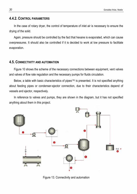
4.5. CONNECTIVITY AND AUTOMATION
Figure 10 shows the scheme of the necessary connections between equipment, vent valves
and valves of flow rate regulation and the necessary pumps for fluids circulation.
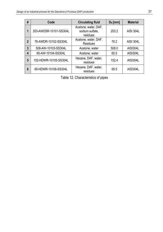
Below, a table with basic characteristics of pipes(18) is presented. It is not specified anything
about feeding pipes or condenser-ejector connection, due to their characteristics depend of
vessels and ejector, respectively.
In reference to valves and pumps, they are shown in the diagram, but it has not specified
anything about them in this project.
Figure 13. Connectivity and automation
Design of an industrial process for the Diacetone-β-Fructose (DAF) production 31
# Code Circulating fluid DN [mm] Material
1 203-AWDSR-10101-SS304L Acetone, water, DAF,
sodium sulfate, residues
203.2 AISI 304L
2 76-AWDR-10102-SS304L Acetone, water, DAF,
Residues 76.2 AISI 304L
3 508-AW-10103-SS304L Acetone, water 508.0 AISI304L
4 65-AW-10104-SS304L Acetone, water 65.5 AISI304L
5 152-HDWR-10105-SS304L Hexane, DAF, water,
residues 152.4 AISI304L
6 65-HDWR-10106-SS304L Hexane, DAF, water,
residues 65.5 AISI304L
Table 12. Characteristics of pipes
32 González Arias, Noelia
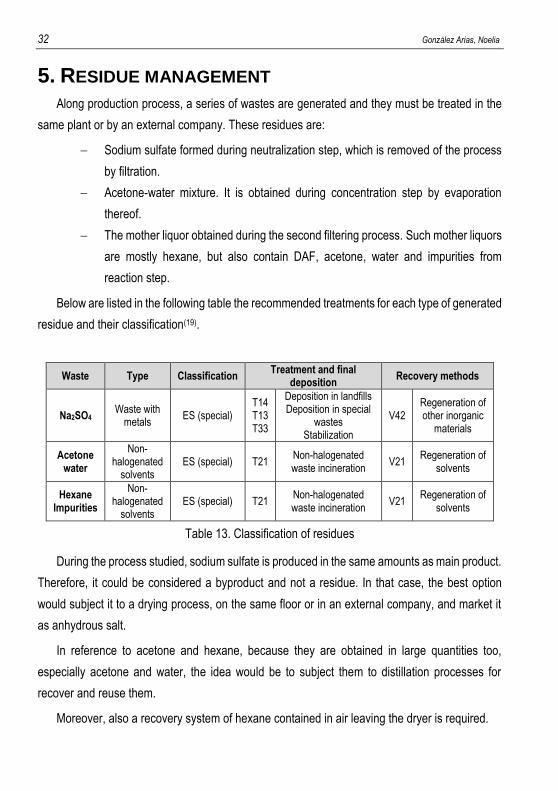
5. RESIDUE MANAGEMENT
Along production process, a series of wastes are generated and they must be treated in the
same plant or by an external company. These residues are:
Sodium sulfate formed during neutralization step, which is removed of the process
by filtration.
Acetone-water mixture. It is obtained during concentration step by evaporation
thereof.
The mother liquor obtained during the second filtering process. Such mother liquors
are mostly hexane, but also contain DAF, acetone, water and impurities from
reaction step.
Below are listed in the following table the recommended treatments for each type of generated
residue and their classification(19).
Waste Type Classification Treatment and final
deposition Recovery methods
Na2SO4 Waste with
metals ES (special)
T14 T13 T33
Deposition in landfills Deposition in special
wastes Stabilization
V42 Regeneration of other inorganic
materials
Acetone water
Non-halogenated
solvents ES (special) T21
Non-halogenated waste incineration
V21 Regeneration of
solvents
Hexane Impurities
Non-halogenated
solvents ES (special) T21
Non-halogenated waste incineration
V21 Regeneration of
solvents
Table 13. Classification of residues
During the process studied, sodium sulfate is produced in the same amounts as main product.
Therefore, it could be considered a byproduct and not a residue. In that case, the best option
would subject it to a drying process, on the same floor or in an external company, and market it
as anhydrous salt.
In reference to acetone and hexane, because they are obtained in large quantities too,
especially acetone and water, the idea would be to subject them to distillation processes for
recover and reuse them.
Moreover, also a recovery system of hexane contained in air leaving the dryer is required.
Design of an industrial process for the Diacetone-β-Fructose (DAF) production 33
6. SCHEDULING
Once known in depth the process, it has made the sizing of equipments and it has decided
which tasks will be carried out in each, it is time to set the pace of production to achieve the annual
demand of product to produce.
6.1. GENERAL CONSIDERATIONS
The annual minimum production of DAF to be achieved is one that is able to meet the needs
of the annual production of 20,000 kg of Topiramate. Since the production of 1 kg of Topiramate
requires approximately 7 kg of DAF, the ultimate goal is to ensure the annual production of
140,000kg DAF. As already mentioned above, the nominal batch size has been chosen is 3500 kg
DAF/batch, so the production scheduling has to ensure the production of 40 batches.
To carry out the programming, it is considered that production takes place 24 h/day (3 shifts),
5 days/week and 48 weeks/year. The remaining time corresponds to maintenance shutdowns.
Given that throughout the year there may be various problems, such as delays due to
breakdown or delays in the receipt of raw materials, etc., it has been assumed that the real-time
production of the plant is about 4500 h/year.
6.2. BATCH TIME
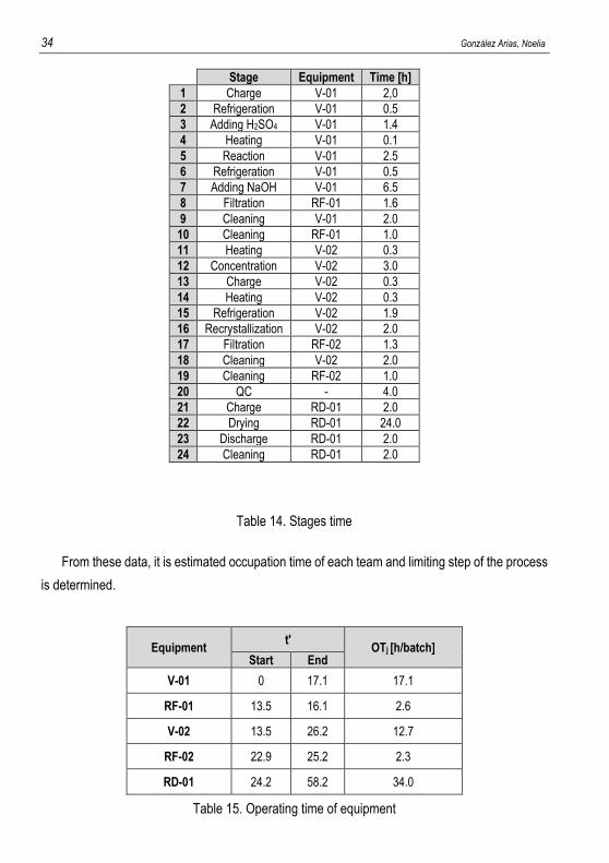
The following table shows the estimated time duration of each stage. It should comment
that have been included in it the time leaning equipment.
34 González Arias, Noelia
Stage Equipment Time [h]
1 Charge V-01 2,0
2 Refrigeration V-01 0.5
3 Adding H2SO4 V-01 1.4
4 Heating V-01 0.1
5 Reaction V-01 2.5
6 Refrigeration V-01 0.5
7 Adding NaOH V-01 6.5
8 Filtration RF-01 1.6
9 Cleaning V-01 2.0
10 Cleaning RF-01 1.0
11 Heating V-02 0.3
12 Concentration V-02 3.0
13 Charge V-02 0.3
14 Heating V-02 0.3
15 Refrigeration V-02 1.9
16 Recrystallization V-02 2.0
17 Filtration RF-02 1.3
18 Cleaning V-02 2.0
19 Cleaning RF-02 1.0
20 QC - 4.0
21 Charge RD-01 2.0
22 Drying RD-01 24.0
23 Discharge RD-01 2.0
24 Cleaning RD-01 2.0
Table 14. Stages time
From these data, it is estimated occupation time of each team and limiting step of the process
is determined.
Equipment t'
OTj [h/batch] Start End
V-01 0 17.1 17.1
RF-01 13.5 16.1 2.6
V-02 13.5 26.2 12.7
RF-02 22.9 25.2 2.3
RD-01 24.2 58.2 34.0
Table 15. Operating time of equipment
Design of an industrial process for the Diacetone-β-Fructose (DAF) production 35
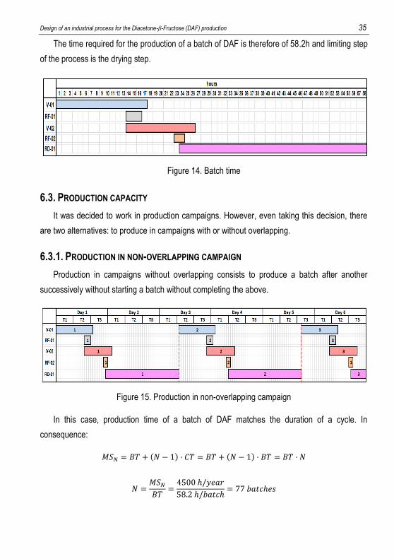
The time required for the production of a batch of DAF is therefore of 58.2h and limiting step
of the process is the drying step.
Figure 14. Batch time
6.3. PRODUCTION CAPACITY
It was decided to work in production campaigns. However, even taking this decision, there
are two alternatives: to produce in campaigns with or without overlapping.
6.3.1. PRODUCTION IN NON-OVERLAPPING CAMPAIGN
Production in campaigns without overlapping consists to produce a batch after another
successively without starting a batch without completing the above.
Figure 15. Production in non-overlapping campaign
In this case, production time of a batch of DAF matches the duration of a cycle. In
consequence:
𝑀𝑆𝑁 = 𝐵𝑇 + (𝑁 − 1) · 𝐶𝑇 = 𝐵𝑇 + (𝑁 − 1) · 𝐵𝑇 = 𝐵𝑇 · 𝑁
𝑁 =𝑀𝑆𝑁𝐵𝑇
=4500 ℎ/𝑦𝑒𝑎𝑟
58.2 ℎ/𝑏𝑎𝑡𝑐ℎ= 77 𝑏𝑎𝑡𝑐ℎ𝑒𝑠
36 González Arias, Noelia
Due the minimum number of batch to produce is 40, it should be seen the possibility of non-
working periods (weekends) involve problems to achieve the desired production.
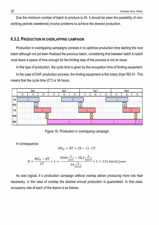
6.3.2. PRODUCTION IN OVERLAPPING CAMPAIGN
Production in overlapping campaigns consists in to optimize production time starting the next
batch although not yet been finalized the previous batch, considering that between batch to batch
must leave a space of time enough for the limiting step of the process is not an issue.
In this type of production, the cycle time is given by the occupation time of limiting equipment.
In the case of DAF production process, the limiting equipment is the rotary dryer RD-01. This
means that the cycle time (CT) is 34 hours.
Figure 16. Production in overlapping campaign
In consequence: 𝑀𝑆𝑁 = 𝐵𝑇 + (𝑁 − 1) · 𝐶𝑇
𝑁 =𝑀𝑆𝑁 − 𝐵𝑇
𝐶𝑇+ 1 =
4500ℎ
𝑦𝑒𝑎𝑟− 58.2
ℎ
𝑏𝑎𝑡𝑐ℎ
34ℎ
𝑏𝑎𝑡𝑐ℎ
+ 1 = 131 𝑏𝑎𝑡𝑐ℎ/𝑦𝑒𝑎𝑟
As was logical, if a production campaign without overlap allows producing more lots than
necessary, in the case of overlap the desired annual production is guaranteed. In that case,
occupancy rate of each of the teams is as follows.
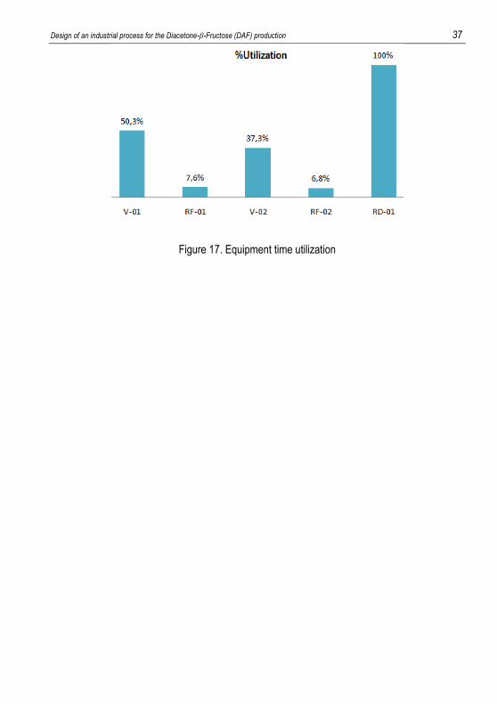
Design of an industrial process for the Diacetone-β-Fructose (DAF) production 37
Figure 17. Equipment time utilization
38 González Arias, Noelia
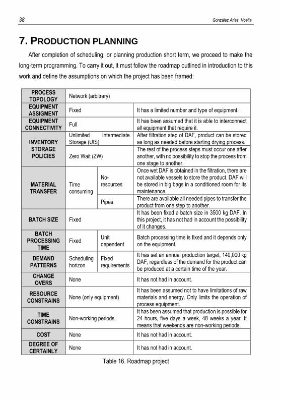
7. PRODUCTION PLANNING
After completion of scheduling, or planning production short term, we proceed to make the
long-term programming. To carry it out, it must follow the roadmap outlined in introduction to this
work and define the assumptions on which the project has been framed:
PROCESS TOPOLOGY
Network (arbitrary)
EQUIPMENT ASSIGMENT
Fixed It has a limited number and type of equipment.
EQUIPMENT CONNECTIVITY
Full It has been assumed that it is able to interconnect all equipment that require it.
INVENTORY STORAGE POLICIES
Unlimited Intermediate Storage (UIS)
After filtration step of DAF, product can be stored as long as needed before starting drying process.
Zero Wait (ZW) The rest of the process steps must occur one after another, with no possibility to stop the process from one stage to another.
MATERIAL TRANSFER
Time consuming
No-resources
Once wet DAF is obtained in the filtration, there are not available vessels to store the product. DAF will be stored in big bags in a conditioned room for its maintenance.
Pipes There are available all needed pipes to transfer the product from one step to another.
BATCH SIZE Fixed It has been fixed a batch size in 3500 kg DAF. In this project, it has not had in account the possibility of it changes.
BATCH PROCESSING
TIME Fixed
Unit dependent
Batch processing time is fixed and it depends only on the equipment.
DEMAND PATTERNS
Scheduling horizon
Fixed requirements
It has set an annual production target, 140,000 kg DAF, regardless of the demand for the product can be produced at a certain time of the year.
CHANGE OVERS
None It has not had in account.
RESOURCE CONSTRAINS
None (only equipment) It has been assumed not to have limitations of raw materials and energy. Only limits the operation of process equipment.
TIME CONSTRAINS
Non-working periods It has been assumed that production is possible for 24 hours, five days a week, 48 weeks a year. It means that weekends are non-working periods.
COST None It has not had in account.
DEGREE OF CERTAINLY
None It has not had in account.
Table 16. Roadmap project
Design of an industrial process for the Diacetone-β-Fructose (DAF) production 39
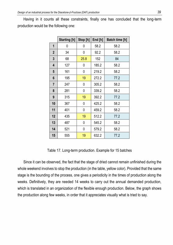
Having in it counts all these constraints, finally one has concluded that the long-term
production would be the following one:
Starting [h] Stop [h] End [h] Batch time [h]
1 0 0 58.2 58.2
2 34 0 92.2 58.2
3 68 25.8 152 84
4 127 0 185.2 58.2
5 161 0 219.2 58.2
6 195 19 272.2 77.2
7 247 0 305.2 58.2
8 281 0 339.2 58.2
9 315 19 392.2 77.2
10 367 0 425.2 58.2
11 401 0 459.2 58.2
12 435 19 512.2 77.2
13 487 0 545.2 58.2
14 521 0 579.2 58.2
15 555 19 632.2 77.2
Table 17. Long-term production. Example for 15 batches
Since it can be observed, the fact that the stage of dried cannot remain unfinished during the
whole weekend involves to stop the production (in the table, yellow color). Provided that the same
stage is the bounding of the process, one gives a periodicity in the times of production along the
weeks. Definitively, they are needed 14 weeks to carry out the annual demanded production,
which is translated in an organization of the flexible enough production. Below, the graph shows
the production along few weeks, in order that it appreciates visually what is tried to say.
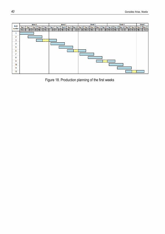
40 González Arias, Noelia
Figure 18. Production planning of the first weeks
Design of an industrial process for the Diacetone-β-Fructose (DAF) production 41
8. FINANCIAL VIABILITY
In the present section, there tries to value the economic viability of the project by means of
the calculation of Net Present Value (NPV), the Discounted Payback and the Internal Rate of
Return (IRR). To be able to determine them is necessary to do an estimation of the initial
necessary investment of the project, the income due to the same one and the operating cost.
From them will be possible calculate the Profit and Loses (P&L), the Cash Flow and consequently
the Discounted Cash Flow (DCF) which are necessary for the calculation of the mentioned
indicators.
8.1. ESTIMATION OF THE INITIAL INVESTMENT
Based on the number and type of necessary equipments and resorting to the information
facilitated by companies of the sector that work with this type of equipments and by suppliers, the
initial investment has been estimated in 4.2 million Euros.
8.2. COST OF GOODS SOLD
First, there are calculated the costs foreseen for the production of 1 lot of finished product.
Some of them have referred to the initial realized investment.
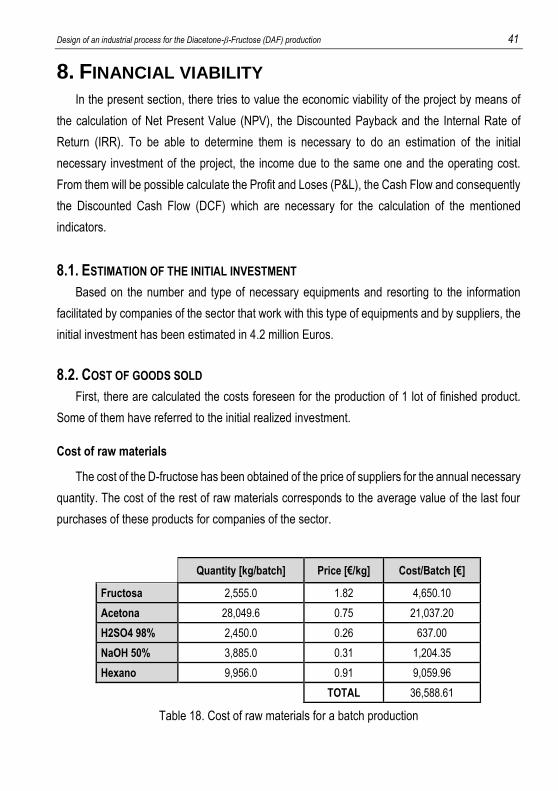
Cost of raw materials
The cost of the D-fructose has been obtained of the price of suppliers for the annual necessary
quantity. The cost of the rest of raw materials corresponds to the average value of the last four
purchases of these products for companies of the sector.
Quantity [kg/batch] Price [€/kg] Cost/Batch [€]
Fructosa 2,555.0 1.82 4,650.10
Acetona 28,049.6 0.75 21,037.20
H2SO4 98% 2,450.0 0.26 637.00
NaOH 50% 3,885.0 0.31 1,204.35
Hexano 9,956.0 0.91 9,059.96
TOTAL 36,588.61
Table 18. Cost of raw materials for a batch production
42 González Arias, Noelia
Cost of packaging
The costs of the packing have been referred to mass of finished product. Price has fixed 0.20
€/kg of finished product, an estimation based on cost that packing similar quantities supposes to
companies of the sector that work with similar products.
The cost of packing for batch is, therefore of:
3500𝑘𝑔𝐷𝐴𝐹
𝑏𝑎𝑡𝑐ℎ·0,20€
𝑘𝑔 𝐷𝐴𝐹= 700
€
𝑏𝑎𝑡𝑐ℎ
Cost of waste management
Like already it has been commented in numerous occasions along this document, during the
process of production of DAF, residues that must be purified are generated. This fact carries a
cost that he must be estimated.
The wet sodium sulfate generated is a residue of not interest in the process. Nevertheless,
the residual liquids of the process consist of big volumes that contain high quantities of acetone
and hexane, solvents used in big quantities to carry out the process. Due to it, his recovery is
important and can suppose a saving.
In calculation of the cost of the raw materials has been considered a price for the acetone and
the hexane bigger than the royal one, since there has not been born in mind that these could be
re-used. This fact has been compensated in the cost estimated of the waste management.
Finally, one has concluded that this one will be around the 3500 €/batch.
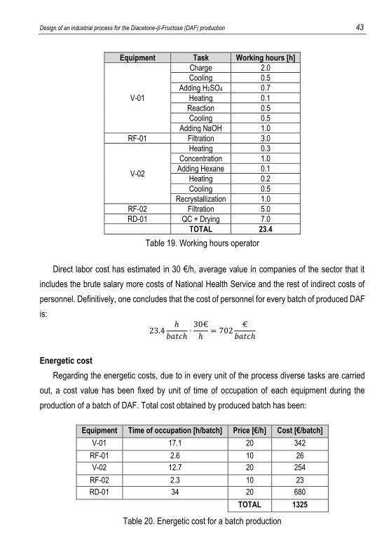
Direct labor cost
It has been carried out an estimation of the hours that an operator is needed in each of the
tasks of the productive process:
Design of an industrial process for the Diacetone-β-Fructose (DAF) production 43
Equipment Task Working hours [h]
V-01
Charge 2.0
Cooling 0.5
Adding H2SO4 0.7
Heating 0.1
Reaction 0.5
Cooling 0.5
Adding NaOH 1.0
RF-01 Filtration 3.0
V-02
Heating 0.3
Concentration 1.0
Adding Hexane 0.1
Heating 0.2
Cooling 0.5
Recrystallization 1.0
RF-02 Filtration 5.0
RD-01 QC + Drying 7.0
TOTAL 23.4
Table 19. Working hours operator
Direct labor cost has estimated in 30 €/h, average value in companies of the sector that it
includes the brute salary more costs of National Health Service and the rest of indirect costs of
personnel. Definitively, one concludes that the cost of personnel for every batch of produced DAF
is:
23.4ℎ
𝑏𝑎𝑡𝑐ℎ·30€
ℎ= 702
€
𝑏𝑎𝑡𝑐ℎ
Energetic cost
Regarding the energetic costs, due to in every unit of the process diverse tasks are carried
out, a cost value has been fixed by unit of time of occupation of each equipment during the
production of a batch of DAF. Total cost obtained by produced batch has been:
Equipment Time of occupation [h/batch] Price [€/h] Cost [€/batch]
V-01 17.1 20 342
RF-01 2.6 10 26
V-02 12.7 20 254
RF-02 2.3 10 23
RD-01 34 20 680
TOTAL 1325
Table 20. Energetic cost for a batch production
44 González Arias, Noelia
Maintenance cost
It has been considered as 2% of the initial necessary investment, that is to say, of
84,000 €/year. Nevertheless, DAF's production is not realized all the year round and in these
periods the equipments will be used for other intentions. Therefore, it is needed to calculate what
part from this cost corresponds to DAF production.
Like already it has been commented in a previous paragraph, the production of the annual
quantity of wished DAF can be carried out in 14 weeks. However, contemplating the possibility
more that probable of that the production will not be realized in only a campaign, it has thought
that the process occupies the facilities for 16 weeks to the year of 48 weeks that the facilities are
operative.
This period of 16 weeks of occupation corresponds to the most unfavorable case, in which
the production it is not carried out in 8 campaigns of 2 weeks. More short campaigns probably
would not be viable because changing the process so often would imply cleanliness so
exhaustive.
For all that, finally one has determined that the costs of maintenance are approximately:
84,000€
𝑦𝑒𝑎𝑟·1 𝑦𝑒𝑎𝑟
48 𝑤𝑒𝑒𝑘𝑠·16 𝑤𝑒𝑒𝑘𝑠
40 𝑏𝑎𝑡𝑐ℎ𝑒𝑠= 700
€
𝑏𝑎𝑡𝑐ℎ
Cost of amortization
In the chemical industry and in agreement with Spanish Accounting Plan, it considers that the
period of useful life of the equipments is 10 years. Supposing a constant amortization and a
residual value ten years of zero, the annual costs of amortization of the installation are of 420,000
€/year.
Again, bearing in mind the period of use of the facilities and the number of batches to produce,
it is obtained:
420,000€
𝑦𝑒𝑎𝑟·1 𝑦𝑒𝑎𝑟
48 𝑤𝑒𝑒𝑘𝑠·16 𝑤𝑒𝑒𝑘𝑠
40 𝑏𝑎𝑡𝑐ℎ𝑒𝑠= 3500
€
𝑏𝑎𝑡𝑐ℎ
Design of an industrial process for the Diacetone-β-Fructose (DAF) production 45
Indirect costs of production
Again, based on the functioning of chemical companies that work with similar products it has
thought that the indirect costs of production will be of approximately 500 €/batch.
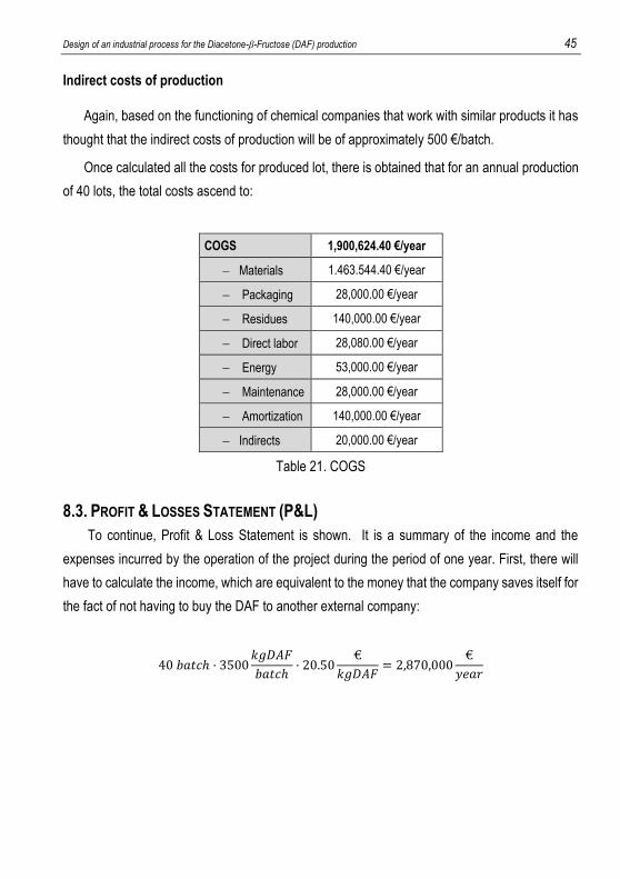
Once calculated all the costs for produced lot, there is obtained that for an annual production
of 40 lots, the total costs ascend to:
COGS 1,900,624.40 €/year
Materials 1.463.544.40 €/year
Packaging 28,000.00 €/year
Residues 140,000.00 €/year
Direct labor 28,080.00 €/year
Energy 53,000.00 €/year
Maintenance 28,000.00 €/year
Amortization 140,000.00 €/year
Indirects 20,000.00 €/year
Table 21. COGS
8.3. PROFIT & LOSSES STATEMENT (P&L)
To continue, Profit & Loss Statement is shown. It is a summary of the income and the
expenses incurred by the operation of the project during the period of one year. First, there will
have to calculate the income, which are equivalent to the money that the company saves itself for
the fact of not having to buy the DAF to another external company:
40 𝑏𝑎𝑡𝑐ℎ · 3500𝑘𝑔𝐷𝐴𝐹
𝑏𝑎𝑡𝑐ℎ· 20.50
€
𝑘𝑔𝐷𝐴𝐹= 2,870,000
€
𝑦𝑒𝑎𝑟
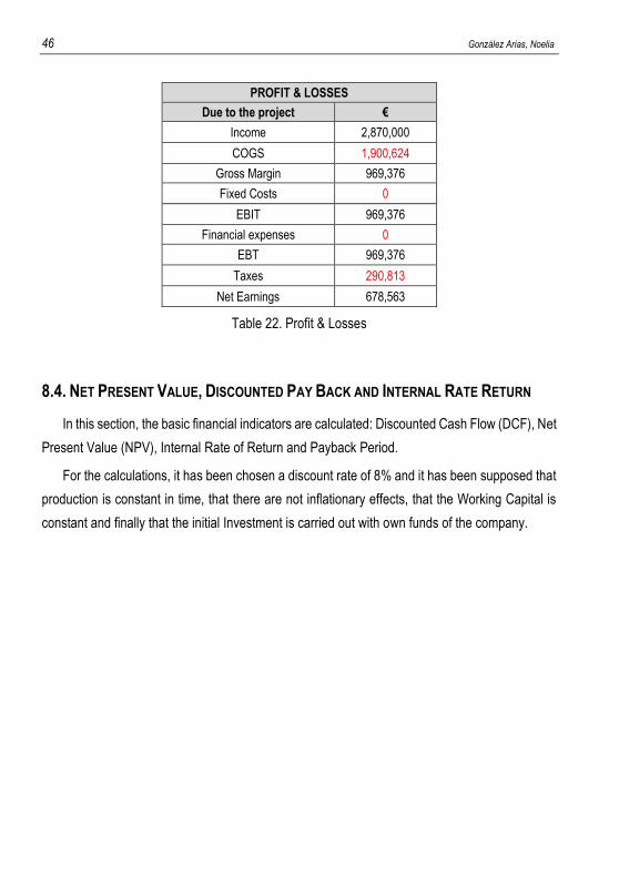
46 González Arias, Noelia
PROFIT & LOSSES
Due to the project €
Income 2,870,000
COGS 1,900,624
Gross Margin 969,376
Fixed Costs 0
EBIT 969,376
Financial expenses 0
EBT 969,376
Taxes 290,813
Net Earnings 678,563
Table 22. Profit & Losses
8.4. NET PRESENT VALUE, DISCOUNTED PAY BACK AND INTERNAL RATE RETURN
In this section, the basic financial indicators are calculated: Discounted Cash Flow (DCF), Net
Present Value (NPV), Internal Rate of Return and Payback Period.
For the calculations, it has been chosen a discount rate of 8% and it has been supposed that
production is constant in time, that there are not inflationary effects, that the Working Capital is
constant and finally that the initial Investment is carried out with own funds of the company.
Design of an industrial process for the Diacetone-β-Fructose (DAF) production 47
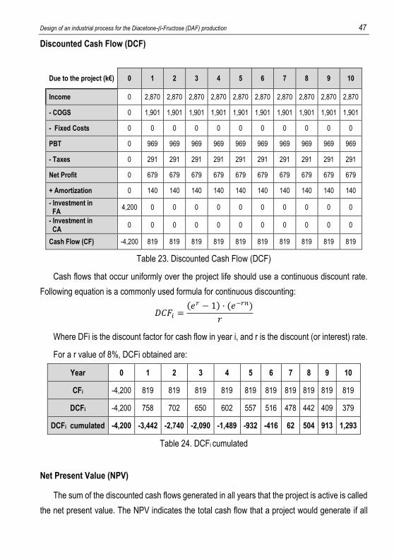
Discounted Cash Flow (DCF)
Due to the project (k€) 0 1 2 3 4 5 6 7 8 9 10
Income 0 2,870 2,870 2,870 2,870 2,870 2,870 2,870 2,870 2,870 2,870
- COGS 0 1,901 1,901 1,901 1,901 1,901 1,901 1,901 1,901 1,901 1,901
- Fixed Costs 0 0 0 0 0 0 0 0 0 0 0
PBT 0 969 969 969 969 969 969 969 969 969 969
- Taxes 0 291 291 291 291 291 291 291 291 291 291
Net Profit 0 679 679 679 679 679 679 679 679 679 679
+ Amortization 0 140 140 140 140 140 140 140 140 140 140
- Investment in FA
4,200 0 0 0 0 0 0 0 0 0 0
- Investment in CA
0 0 0 0 0 0 0 0 0 0 0
Cash Flow (CF) -4,200 819 819 819 819 819 819 819 819 819 819
Table 23. Discounted Cash Flow (DCF)
Cash flows that occur uniformly over the project life should use a continuous discount rate.
Following equation is a commonly used formula for continuous discounting:
𝐷𝐶𝐹𝑖 =(𝑒𝑟 − 1) · (𝑒−𝑟𝑛)
𝑟
Where DFi is the discount factor for cash flow in year i, and r is the discount (or interest) rate.
For a r value of 8%, DCFi obtained are:
Year 0 1 2 3 4 5 6 7 8 9 10
CFi -4,200 819 819 819 819 819 819 819 819 819 819
DCFi -4,200 758 702 650 602 557 516 478 442 409 379
DCFi cumulated -4,200 -3,442 -2,740 -2,090 -1,489 -932 -416 62 504 913 1,293
Table 24. DCFi cumulated
Net Present Value (NPV)
The sum of the discounted cash flows generated in all years that the project is active is called
the net present value. The NPV indicates the total cash flow that a project would generate if all
48 González Arias, Noelia
revenues and costs associated with the project were reduced to a single instant in time, namely
present. NPV is calculated by:
𝑁𝑃𝑉𝑖 =∑𝐷𝐶𝐹𝑖
𝑖
1
Where i is the number of periods of evaluation.
The NPV10 obtained for this project is 1,293 k€.
The interpretation of an NPV is relatively simple: If NPV>0, like in this case, the project will
return more than the opportunity cost of funds. However, if NPV<0, the project will not return the
opportunity cost of funds.
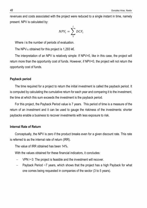
Payback period
The time required for a project to return the initial investment is called the payback period. It
is computed by calculating the cumulative return for each year and comparing it to the investment,
the time at which this sum exceeds the investment is the payback period.
For this project, the Payback Period value is 7 years. This period of time is a measure of the
return of an investment and it can be used to gauge the riskiness of the investments: shorter
paybacks enable a business to recover investments with less exposure to risk.
Internal Rate of Return
Conceptually, the NPV is zero if the product breaks even for a given discount rate. This rate
is referred to as the internal rate of return (IRR).
The value of IRR obtained has been 14%.
With the values obtained for these financial indicators, it concludes:
VPN > 0: The project is feasible and the investment will recover.
Payback Period ≈7 years, which shows that the project has a high Payback for what
one comes being requested in companies of the sector (3 to 5 years).
Design of an industrial process for the Diacetone-β-Fructose (DAF) production 49
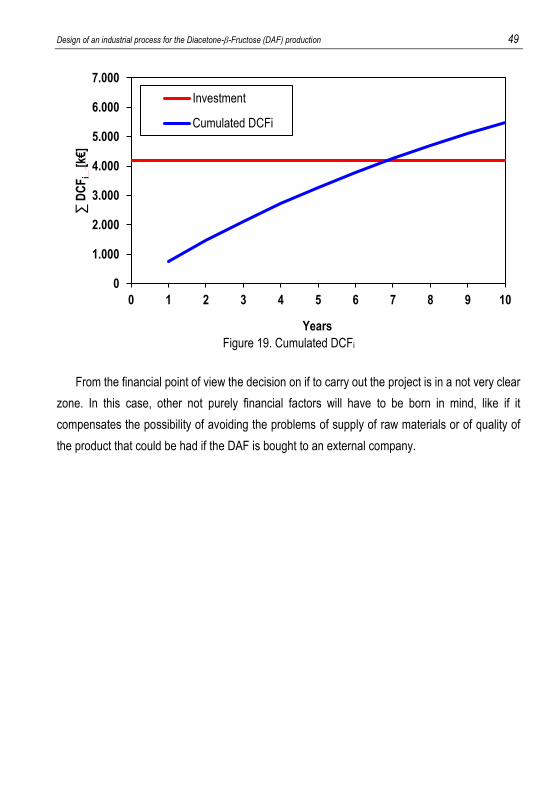
Figure 19. Cumulated DCFi
From the financial point of view the decision on if to carry out the project is in a not very clear
zone. In this case, other not purely financial factors will have to be born in mind, like if it
compensates the possibility of avoiding the problems of supply of raw materials or of quality of
the product that could be had if the DAF is bought to an external company.
0
1.000
2.000
3.000
4.000
5.000
6.000
7.000
0 1 2 3 4 5 6 7 8 9 10
∑ D
CF
i [k
€]
Years
Investment
Cumulated DCFi
50 González Arias, Noelia
9. CONCLUSIONS
Once concluded this project, there are exposed the obtained conclusions in reference with
the initial aims of the project:
Bearing in mind that it is wanted to carry out the production with the minimal number
of equipments, one has concluded that are necessary: 2 vessels (reactors), 2
rotating filters and a rotating dryer, each one with its respective auxiliary necessary
equipments, automation and control.
o The two vessels are necessary because on having had to leak big
volumes, it has been chosen for filtrations in continuous, so minimum is
needed two vessels, the vessel in use and a second where to be leading
the volume of already leaked liquid.
o As for the rotary filters, it could have been decided to use an only filter.
Nevertheless, the fact that first the solid crystalline is filtered and then the
solid porous organic, it involves that the mesh has to be replaced in each
occasion. In addition, in the second filtration the wished product is
obtained and it is tried to be obtained with a very high purity, for what the
use of an only one filter would force to carry out too careful processes of
cleanliness.
According to the chapter 3.2, it has concluded that batches of 3500 kg of DAF will
be produced, the half of the necessary to produce one batch of Topiramate.
The sizing of the equipments has been realized bearing in mind the way and the
conditions of operation, as well as the fact that they are the same equipments those
who limit the development of process. Finally, one has concluded that the tanks will
be of the same size, of approximately 44.2 m3, whereas both filters will be different
between them. The first one will be of 3.80x2.05X1.70 m, whereas the second one
will be low, of 4.30x2.30x2.00 m. To finish, the rotating dryer will be of 1.20x1.20 m.
Design of an industrial process for the Diacetone-β-Fructose (DAF) production 51
From the analysis of the functioning of the equipments in each stage, one has
concluded that the time of batch, including the times of cleanliness of the
equipments, is of 58.2 h. The bounding stage of the process is the stage of dried,
which lasts 34 hours and fixes the time of a cycle. From the accomplishment of the
scheduling, one has concluded that, in campaigns with overlapping, the most
feasible form of production for the saving in time of occupation of the equipments,
the wished production could be carry out, at best, in only 14 weeks. However,
foreseeing the worst of the cases in which the production was realized in campaigns
of two weeks, 16 weeks would be sufficient, which means that the process presents
flexibility in the distribution of the production throughout the year.
By means of the calculation of the financial basic indicators, one has concluded that
from the financial point of view, the viability of the starting up of the project is not
clear. The initial estimated investment is of 4,200,000 € and the obtained Payback
Period has been of approximately 7 years, a bit high for what one comes asking in
the industries of the sector (from 3 to 5 years), by what to take the decision other
factors will have to be born in mind, in addition to the purely financial ones, like it
can be the possibility of save the problems related with the supply of the raw
materials or with the quality of the received product.
RECOMMENDATIONS
Of all the information extracted along the accomplishment of this project, they propose some
recommendations for those that are interested in looking to beyond into this topic:
One of the longest stages of the process is the stage of neutralization. His exothermic
character forces to carry out the stage of slow form and with a very exhaustive control
of the temperature. It would propose to realize studies in laboratory on how to improve
the selectivity of the reaction without need to need a pH so acid, that way the duration
of the stage of neutralization would be shorter
52 González Arias, Noelia
The most important losses of product are caused by the dissolution of the DAF in the
solvents that are withdrawn from the principal line of the process. It would be interesting
to try of taking the reaction to higher concentrations, with what the quantities of solvents
to use you would be minor.
The sodium sulfate is a by-product of the process that is produced practically in the
same quantities that the principal product. It would be advisable to realize a study to
see what can be done to save the expenses that it produces as residue.
Design of an industrial process for the Diacetone-β-Fructose (DAF) production 53
10. REFERENCES AND NOTES
1. Gobierno de España. (2016). Agencia Española de Medicamentos y Productos Sanitarios. . Recovered of http://www.aemps.gob.es (February, 2016).
2. Moser, A. (2008). Producción del Topiramato: Elección de la vía de síntesis y estudios en planta piloto (Trabajo Final de Carrera) Ingeniería Química. Universitat de Barcelona.
3. Batchu, C., Kumar, B., Bhirud, S. (2005). Process for the preparation of sulfamate derivatives. Recovered of http://worldwide.espacenet.com (March, 2016).
4. Maryanoff, C., Sorgi, L., Scott, L. (1993). Process for the preparation of chlorosulfate and sulfamate derivatives of 2,3:4,5-bis-O-(1-methylethylidene)-beta-D-fructopyranose and (1-methylcyclohexyl)methanol. Recovered of http//register.epo.org (March, 2016).
5. Ferreira, V., Silva, F. (2001). Sacarose no laboratória de química orgánica de graduação. Ed. Quim
Nova, Vol. 24, 6, 905-907. 6. Espuña, A. (1994). Contribución al estudio de plantas químicas multiproducto de procesos discontinuos
(Tesis doctoral no publicada). Escola tècnica superior d’enginyers industrials de Barcelona. Recovered of http://www.tdx.cat (May, 2016).
7. Biegler, L.T., Grossmann, I.E., Westerberg, A.W. (1997) Systematic methods of chemical process design. Ed. Prentice Hall.
8. Diwekar, U. (2014). Batch Processing: Modeling and Design. Ed. CRC Press, Tayloe & Francis Group. 9. Shallcross, D.C. (1996). Psychrometric charts for hydrocarbon vapours in nitrogen; Calphah, Vol 20, 3,
273-288. Ed. Elsevier Science. 10. Massó, Y. (2008) El aislamiento térmico en el nuevo RITE. El Artículo, 22-24. 11. Grup TEFSA. (2016). FIltros Rotativos a vacío. Técnicas de filtración S.A. Recovered of
http://www.gruptefsa.com (May, 2016). 12. Happel, J., Jordan, D.G. (1981). Economía de los procesos químicos. Ed. Reverté S.A.. 13 Perry, R. (1999). Perry’s Chemical engineers’ handbook. Ed. McGraw Hill. 14. Kilfrost. (2012). SFD – Specialty Fluids Division: Guía de Asistencia Técnica, Recovered of
http://www.kilfrost.com (April, 2016). 15. Coulson, J, Richardson, J. (1983) Chemical engineering design. Ed. Elsevier Science. 16. Aguirre, K.C. (2010). Diseño de un condensador barométrico tipo bandeja perforada sencilla para un
sistema de evaporación. Universidad de San Carlos. 17. Taicheng Machinery. (2016). Rotary dryer specifications. Recovered of http://www.hncrusher.com
(June, 2016). 18. Fortinox. (2016). Tuberías y accesorios de acero inoxidable.. Recovered of http://www.fortinox.com
(June, 2016). 19. Generalitat de Catalunya. (2016). Catàleg de Residus de Catalunya. Recovered of
http://www.gencat.cat (April, 2016). 20. Gobierno de España. (2016). Ministerio de Empleo y Seguridad Laboral. Fichas Internacionales de
Seguridad Química. Recovered of http://www.insht.es (February, 2016).

Design of an industrial process for the Diacetone-β-Fructose (DAF) production 55
11. ACRONYMS
CA: Current Assets
CF: Cash Flow
COGS: Cost of Goods Sold
CQ: Control Quality
DAF: Diacetone-β-fructose
DCF: Discounted Cash Flow
EBIT: Earnings Before Interests and Taxes
EBT: Earnings Before Taxes
FA: Fixed Assets
FIS: Finite Intermediate Storage
HE: Heat Exchanger
IRR: Internal Rate of Return
NIS: No intermediate Storage
NPV: Net Present Value
P&L: Profit and Losses
PBT: Profit Before Taxes
RD: Rotary dryer
RF: Rotary Filter
V: Vessel
VIS: Unlimited Intermediate Storage
ZW: Zero wait
56 González Arias, Noelia
12. NOMENCLATURE
As: Cross flow area [m2]
ATUBE: Area of a tube [m]
BT: Batch time [h]
c: Thickness [mm]
Cp: Calorific capacity [J/(kg·K)]
CT: Cycle time [h]
Db: Diameter of tubular bundle [mm]
DCFi: Discount factor for cash flow in year i
Dd: Diameter of the baffle [m]
Deq: Equivalent diameter [m]
Dext,c: External diameter of the shell [m]
Dext,t: External diameter of tubes [m]
Di: Impellier diameter [m]
Dint,c: Internal diameter of the shell [m]
Dint,t: Internal diameter of tubes [m]
DN: Nominal diameter [m]
Dt: Tank diameter [m]
Ed: Spread between baffles [m]
g: Gravity [m/s2]
Gs: Linear velocity of vapor [kg/s]
hc: Individual coefficient of heat transfer [W/(m2·K)]
jh: Factor of heat transfer [-]
kr: Coefficient of material transfer [J/(s·m·K)]
L: Length [m]
lB: Leugth of the baffle [m]
Design of an industrial process for the Diacetone-β-Fructose (DAF) production 57
M: Molecular mass [g/mol]
mi: Mass of i [kg]
MSn: Makespan [h]
N: Number of batches
N: Turn speed [rpm]
NB: Number of baffles [-]
Np: Power number
NT,pass: Number of tubes by pass [tubes]
NT: Number of tubes [tubes]
Nu: Nusselt [-]
OTj: Occupation time of j [h]
P: Pressure [Pa]
Pr: Prandlt [-]
Pt: Tube pitch [mm]
Q: Exchanged heat [W]
q: Volumetric flow rate [m3/s]
r: Discount rate [-]
Re: Reynolds [-]
Scol: Column section [m2]
ST: Section of a tube [m2]
STOTAL: Total section [m2]
T: Temperature [ºC]
t: Time
ti: Inlet temperature of coolant [ºC]
to: Outlet temperature of coolant [ºC]
V: Volume [m3]
Vr: Linear speed of coolant [m/s]
Wi: Impellier width [m]
58 González Arias, Noelia
Wr: Coolant flow rate [kg/s]
Wv: Vapor flow rate [kg/s]
zi: Height of i [m]
Δhdiss: Enthalpy of dissolution [J/mol]
Δhr: Enthalpy of reaction [J/mol]
ΔT: Difference of temperature [K]
λ: Latent heat [J/kg]
μi: viscosity of i [Pa·s]
ρ: Density [kg/m3]
σLE: Elastic yield [Pa]
Design of an industrial process for the Diacetone-β-Fructose (DAF) production 59
13. INDEX OF FIGURES AND TABLES FIGURES
Figure 1. Forming reaction of Topiramate 7
Figure 2. Routes of synthesis of DAF 8
Figure 3. Overall diagram of the inputs and outputs of the production of DAF 12
Figure 4. Stages of synthesis process of DAF 14
Figure 5. Distribution of the tasks on the equipments 16
Figure 6. Material balance representation 18
Figure 7. Variations of mass in vessel V-01 21
Figure 8. Variations of temperature in vessel V-01 22
Figure 9. Rotary filter 23
Figure 10. Scheme of a shell and tube condenser 26
Figure 11. Variations of mass in vessel V-02 27
Figure 12. Variations of temperature in vessel V-02 28
Figure 13. Connectivity and automation 30
Figure 14. Batch time 35
Figure 15. Production in non-overlapping campaign 35
Figure 16. Production in overlapping campaign 36
Figure 17. Equipment time utilization 37
Figure 18. Production planning of the first weeks 40
Figure 19. Cumulated DCF, 49
Figure 20. Global material balance 73
Figure 21. Table individual coefficients of heat transfer 82
Figure 21. Factor of heat transfer depending on the Reynolds 84
Figure 22. Psychrometric diagram hexane-air 91
TABLES
Table 1. Summary of patents of synthesis with D-Fructose 8
Table 2. Summary of patents of synthesis with Sucrose 9
Table 3. Roadmap of production planning 10
Table 4. Mass of raw materials for 1Kg of DAF production 16
Table 5. Characteristics of vessel V-01 19
Table 6. Characteristics of agitation system 20
Table 7. Characteristics of coils 21
60 González Arias, Noelia
Table 8. Characteristics of rotary filters RF-02 23
Table 9. Operating conditions of rotary filters 24
Table 10. Characteristics of barometric condenser 26
Table 11. Characteristics of rotary dryer RD-01 29
Table 12. Characteristics of pipes 31
Table 13. Classification of residues 32
Table 14. Stages time 34
Table 15. Operating time of equipment 34
Table 16. Roadmap project 38
Table 17. Long-term production. Example for 15 batches 39
Table 18. Cost of raw materials for a batch production 41
Table 19. Working hours operator 43
Table 20. Energetic cost for a batch production 44
Table 21. COGS 45
Table 22. Profit & Losses 46
Table 23. Discounted cash flow (DCF) 47
Table 24. DCF, cumulated 47
Table 25. Contained of Vessel V-01 74
Table 26. Specifications of V-01 74
Table 27. Characteristics of an anchor stirrer 75
Table 28. Characteristics of agitation system 75
Table 29. Parameters of agitation dependents of the regime 76
Table 30. Power of agitation 76
Table 31. Parameters for tubular bundle design 79
Table 32. Relation tubular bundle – size of shell 80
Table 33. Calculus of coolings 86
Table 34. Calculus of heatings 87
Table 35. Adding stages 88
Table 36. V-01 specifications sheet 93
Table 37. V-02 specifications sheet 94
Table 38. Anchor agitator V-01 specifications sheet 95
Table 39. Anchor agitator V-02 specifications sheet 96
Table 10. Paddle agitator V-01 specifications sheet 97
Table 41. Paddle agitator V-02 specifications sheet 98
Table 42. RF-01 specifications sheet 99
Table 43. RF-02 specifications sheet 100
Table 44. RD-01 specifications sheet 101
Table 45. HE-01 specifications sheet 102

Design of an industrial process for the Diacetone-β-Fructose (DAF) production 61
APPENDICES

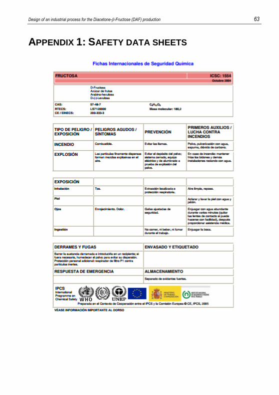
Design of an industrial process for the Diacetone-β-Fructose (DAF) production 63
APPENDIX 1: SAFETY DATA SHEETS
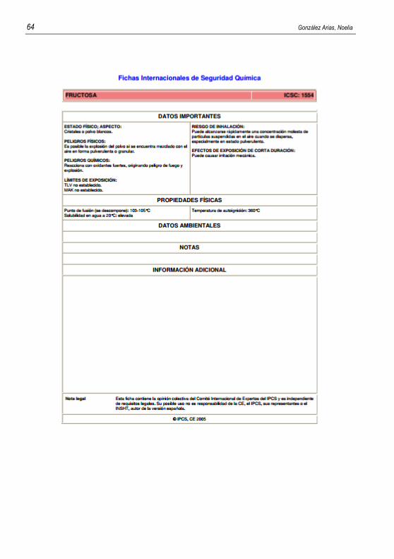
64 González Arias, Noelia
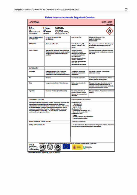
Design of an industrial process for the Diacetone-β-Fructose (DAF) production 65
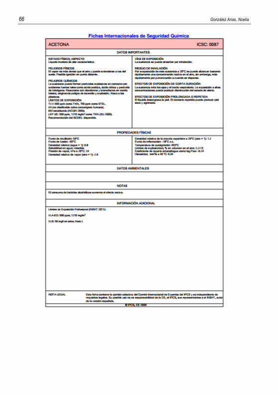
66 González Arias, Noelia
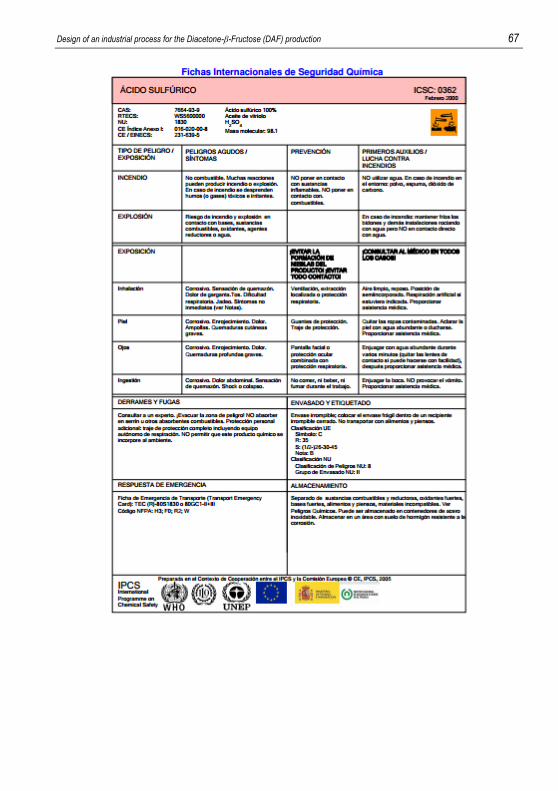
Design of an industrial process for the Diacetone-β-Fructose (DAF) production 67
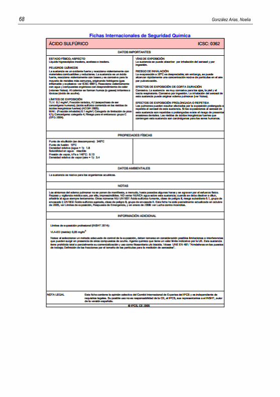
68 González Arias, Noelia
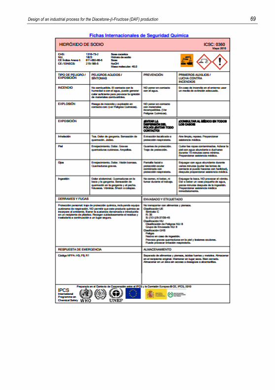
Design of an industrial process for the Diacetone-β-Fructose (DAF) production 69

70 González Arias, Noelia
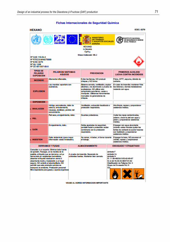
Design of an industrial process for the Diacetone-β-Fructose (DAF) production 71
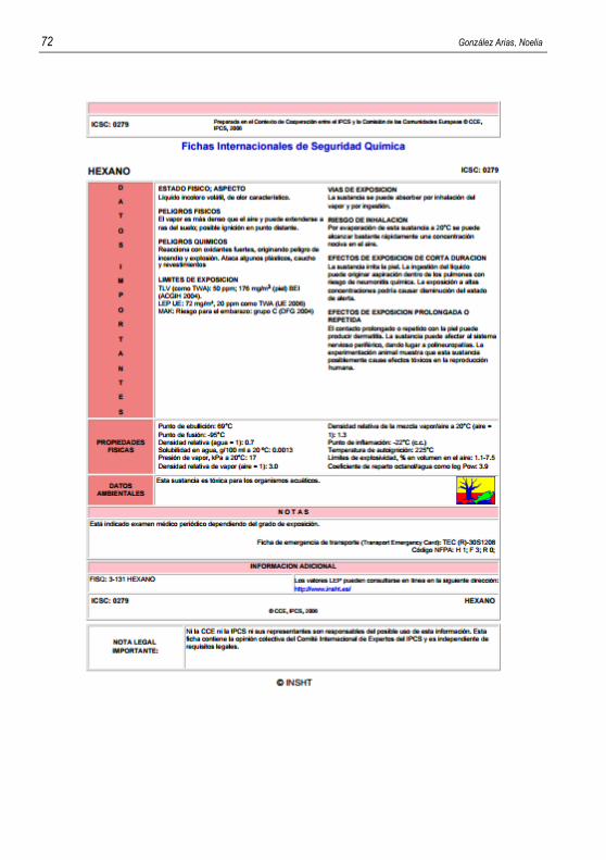
72 González Arias, Noelia
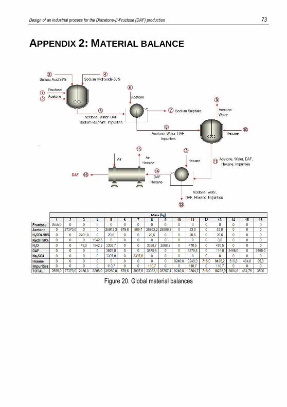
Design of an industrial process for the Diacetone-β-Fructose (DAF) production 73
APPENDIX 2: MATERIAL BALANCE
Figure 20. Global material balances
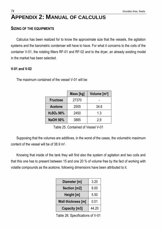
74 González Arias, Noelia
APPENDIX 2: MANUAL OF CALCULUS
SIZING OF THE EQUIPMENTS
Calculus has been realized for to know the approximate size that the vessels, the agitation
systems and the barometric condenser will have to have. For what it concerns to the coils of the
container V-01, the rotating filters RF-01 and RF-02 and to the dryer, an already existing model
in the market has been selected.
V-01 and V-02
The maximum contained of the vessel V-01 will be:
Mass [kg] Volume [m3]
Fructose 27370 -
Acetone 2555 34.6
H2SO4 98% 2450 1.3
NaOH 50% 3885 2.9
Table 25. Contained of Vessel V-01
Supposing that the volumes are additives, in the worst of the cases, the volumetric maximum
content of the vessel will be of 38.9 m3.
Knowing that inside of the tank they will find also the system of agitation and two coils and
that this one has to present between 15 and one 20 % of volume free by the fact of working with
volatile compounds as the acetone, following dimensions have been attributed to it.
Diameter [m] 3.20
Section [m2] 8.00
Height [m] 5.50
Wall thickness [m] 0.01
Capacity [m3] 44.20
Table 26: Specifications of V-01
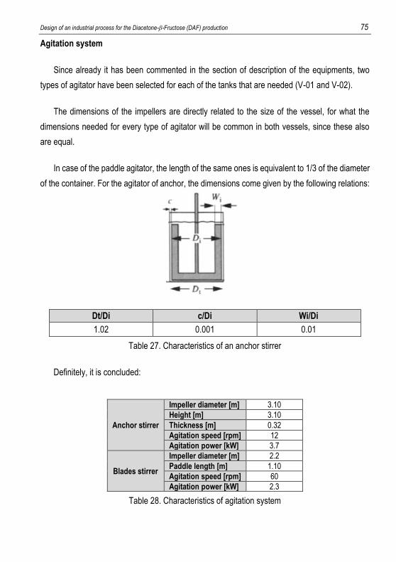
Design of an industrial process for the Diacetone-β-Fructose (DAF) production 75
Agitation system
Since already it has been commented in the section of description of the equipments, two
types of agitator have been selected for each of the tanks that are needed (V-01 and V-02).
The dimensions of the impellers are directly related to the size of the vessel, for what the
dimensions needed for every type of agitator will be common in both vessels, since these also
are equal.
In case of the paddle agitator, the length of the same ones is equivalent to 1/3 of the diameter
of the container. For the agitator of anchor, the dimensions come given by the following relations:
Dt/Di c/Di Wi/Di
1.02 0.001 0.01
Table 27. Characteristics of an anchor stirrer
Definitely, it is concluded:
Anchor stirrer
Impeller diameter [m] 3.10
Height [m] 3.10
Thickness [m] 0.32
Agitation speed [rpm] 12
Agitation power [kW] 3.7
Blades stirrer
Impeller diameter [m] 2.2
Paddle length [m] 1.10
Agitation speed [rpm] 60
Agitation power [kW] 2.3
Table 28. Characteristics of agitation system
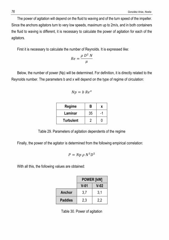
76 González Arias, Noelia
The power of agitation will depend on the fluid to waving and of the turn speed of the impeller.
Since the anchors agitators turn to very low speeds, maximum up to 2m/s, and in both containers
the fluid to waving is different, it is necessary to calculate the power of agitation for each of the
agitators.
First it is necessary to calculate the number of Reynolds. It is expressed like:
𝑅𝑒 =𝜌 𝐷2 𝑁
𝜇
Below, the number of power (Np) will be determined. For definition, it is directly related to the
Reynolds number. The parameters b and x will depend on the type of regime of circulation:
𝑁𝑝 = 𝑏 𝑅𝑒𝑥
Regime B x
Laminar 35 -1
Turbulent 2 0
Table 29. Parameters of agitation dependents of the regime
Finally, the power of the agitator is determined from the following empirical correlation:
𝑃 = 𝑁𝑝 𝜌 𝑁3𝐷5
With all this, the following values are obtained:
POWER [kW]
V-01 V-02
Anchor 3,7 3,1
Paddles 2,3 2,2
Table 30. Power of agitation
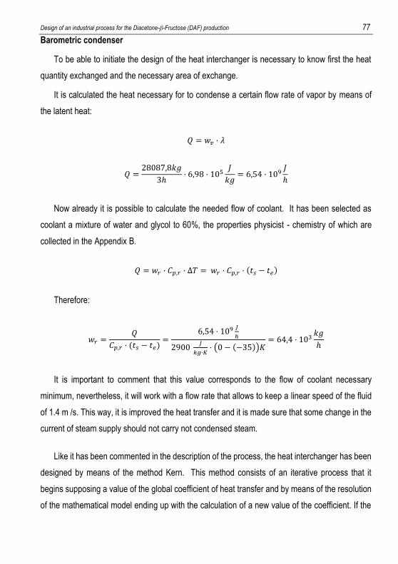
Design of an industrial process for the Diacetone-β-Fructose (DAF) production 77
Barometric condenser
To be able to initiate the design of the heat interchanger is necessary to know first the heat
quantity exchanged and the necessary area of exchange.
It is calculated the heat necessary for to condense a certain flow rate of vapor by means of
the latent heat:
𝑄 = 𝑤𝑣 · 𝜆
𝑄 =28087,8𝑘𝑔
3ℎ· 6,98 · 105
𝐽
𝑘𝑔= 6,54 · 109
𝐽
ℎ
Now already it is possible to calculate the needed flow of coolant. It has been selected as
coolant a mixture of water and glycol to 60%, the properties physicist - chemistry of which are
collected in the Appendix B.
𝑄 = 𝑤𝑟 · 𝐶𝑝,𝑟 · ∆𝑇 = 𝑤𝑟 · 𝐶𝑝,𝑟 · (𝑡𝑠 − 𝑡𝑒)
Therefore:
𝑤𝑟 =𝑄
𝐶𝑝,𝑟 · (𝑡𝑠 − 𝑡𝑒)=
6,54 · 109𝐽
ℎ
2900 𝐽
𝑘𝑔·𝐾· (0 − (−35))𝐾
= 64,4 · 103𝑘𝑔
ℎ
It is important to comment that this value corresponds to the flow of coolant necessary
minimum, nevertheless, it will work with a flow rate that allows to keep a linear speed of the fluid
of 1.4 m /s. This way, it is improved the heat transfer and it is made sure that some change in the
current of steam supply should not carry not condensed steam.
Like it has been commented in the description of the process, the heat interchanger has been
designed by means of the method Kern. This method consists of an iterative process that it
begins supposing a value of the global coefficient of heat transfer and by means of the resolution
of the mathematical model ending up with the calculation of a new value of the coefficient. If the
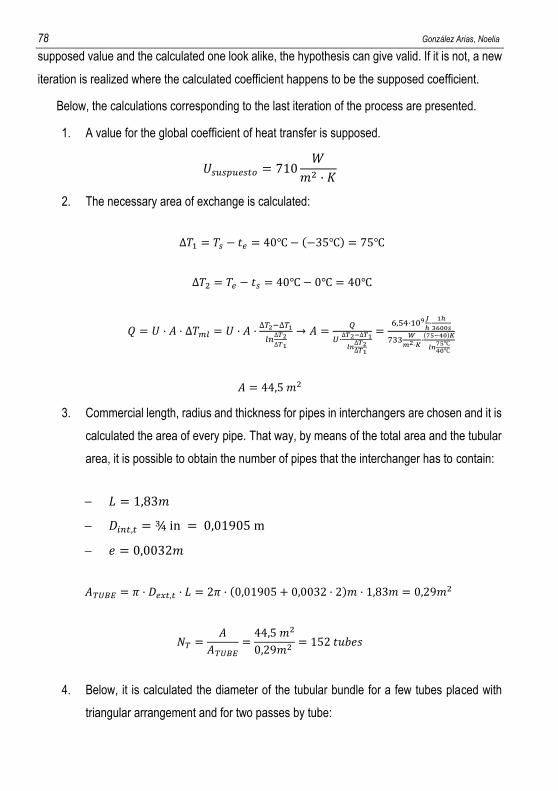
78 González Arias, Noelia
supposed value and the calculated one look alike, the hypothesis can give valid. If it is not, a new
iteration is realized where the calculated coefficient happens to be the supposed coefficient.
Below, the calculations corresponding to the last iteration of the process are presented.
1. A value for the global coefficient of heat transfer is supposed.
𝑈𝑠𝑢𝑠𝑝𝑢𝑒𝑠𝑡𝑜 = 710𝑊
𝑚2 · 𝐾
2. The necessary area of exchange is calculated:
∆𝑇1 = 𝑇𝑠 − 𝑡𝑒 = 40℃− (−35℃) = 75℃
∆𝑇2 = 𝑇𝑒 − 𝑡𝑠 = 40℃− 0℃ = 40℃
𝑄 = 𝑈 · 𝐴 · ∆𝑇𝑚𝑙 = 𝑈 · 𝐴 ·∆𝑇2−∆𝑇1
𝑙𝑛∆𝑇2∆𝑇1
→ 𝐴 =𝑄
𝑈·∆𝑇2−∆𝑇1
𝑙𝑛∆𝑇2∆𝑇1
=6,54·109
𝐽
ℎ·1ℎ
3600𝑠
733𝑊
𝑚2·𝐾·(75−40)𝐾
𝑙𝑛75℃40℃
𝐴 = 44,5 𝑚2
3. Commercial length, radius and thickness for pipes in interchangers are chosen and it is
calculated the area of every pipe. That way, by means of the total area and the tubular
area, it is possible to obtain the number of pipes that the interchanger has to contain:
𝐿 = 1,83𝑚
𝐷𝑖𝑛𝑡,𝑡 = ¾ in = 0,01905 m
𝑒 = 0,0032𝑚
𝐴𝑇𝑈𝐵𝐸 = 𝜋 · 𝐷𝑒𝑥𝑡,𝑡 · 𝐿 = 2𝜋 · (0,01905 + 0,0032 · 2)𝑚 · 1,83𝑚 = 0,29𝑚2
𝑁𝑇 =𝐴
𝐴𝑇𝑈𝐵𝐸=44,5 𝑚2
0,29𝑚2 = 152 𝑡𝑢𝑏𝑒𝑠
4. Below, it is calculated the diameter of the tubular bundle for a few tubes placed with
triangular arrangement and for two passes by tube:
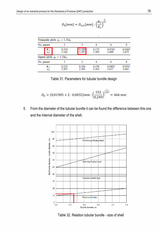
Design of an industrial process for the Diacetone-β-Fructose (DAF) production 79
𝐷𝑏[𝑚𝑚] = 𝐷𝑒𝑥𝑡[𝑚𝑚] · (𝑁𝑇𝐾1)
1
𝑛1
Table 31. Parameters for tubular bundle design
𝐷𝑏 = (0,01905 + 2 · 0,0032)𝑚𝑚 · (152
0,249)
1
2,207
= 466 𝑚𝑚
5. From the diameter of the tubular bundle it can be found the difference between this one
and the internal diameter of the shell.
Table 32. Relation tubular bundle - size of shell
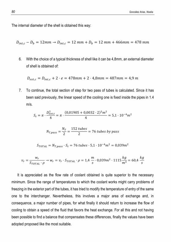
80 González Arias, Noelia
The internal diameter of the shell is obtained this way:
𝐷𝑖𝑛𝑡,𝑐 − 𝐷𝑏 = 12𝑚𝑚 → 𝐷𝑖𝑛𝑡,𝑐 = 12 𝑚𝑚 + 𝐷𝑏 = 12 𝑚𝑚 + 466𝑚𝑚 = 478 𝑚𝑚
6. With the choice of a typical thickness of shell like it can be 4,8mm, an external diameter
of shell is obtained of:
𝐷𝑒𝑥𝑡,𝑐 = 𝐷𝑖𝑛𝑡,𝑐 + 2 · 𝑒 = 478𝑚𝑚 + 2 · 4,8𝑚𝑚 = 487𝑚𝑚 = 4,9 𝑚
7. To continue, the total section of step for two pass of tubes is calculated. Since it has
been said previously, the linear speed of the cooling one is fixed inside the pipes in 1.4
m/s.
𝑆𝑡 = 𝜋 ·𝐷𝑒𝑥𝑡,𝑡2
4= 𝜋 ·
(0,01905 + 0,0032 · 2)2𝑚2
4= 5,1 · 10−4𝑚2
𝑁𝑇,𝑝𝑎𝑠𝑠 =𝑁𝑇2=152 𝑡𝑢𝑏𝑒𝑠
2= 76 𝑡𝑢𝑏𝑒𝑠 𝑏𝑦 𝑝𝑎𝑠𝑠
𝑆𝑇𝑂𝑇𝐴𝐿 = 𝑁𝑇,𝑝𝑎𝑠𝑠 · 𝑆𝑡 = 76 𝑡𝑢𝑏𝑒𝑠 · 5,1 · 10−4𝑚2 = 0,039𝑚2
𝑣𝑟 =𝑤𝑟
𝑆𝑇𝑂𝑇𝐴𝐿 · 𝜌→ 𝑤𝑟 = 𝑣𝑟 · 𝑆𝑇𝑂𝑇𝐴𝐿 · 𝜌 = 1,4
𝑚
𝑠· 0,039𝑚2 · 1115
𝑘𝑔
𝑚3= 60,4
𝑘𝑔
𝑠
It is appreciated as the flow rate of coolant obtained is quite superior to the necessary
minimum. Since the range of temperatures to which the coolant works might carry problems of
freezing in the exterior part of the tubes, it has tried to modify the temperature of entry of the same
one to the interchanger. Nevertheless, this involves a major area of exchange and, in
consequence, a major number of pipes, for what finally it should return to increase the flow of
cooling to obtain a speed of the fluid that favors the heat exchange. For all this and not having
been possible to find a balance that compensates these differences, finally the values have been
adopted proposed like the most suitable.
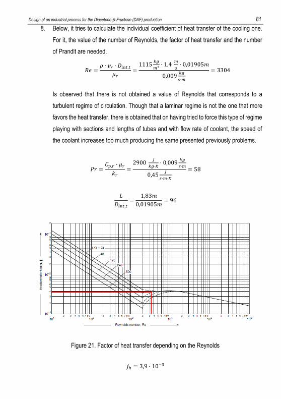
Design of an industrial process for the Diacetone-β-Fructose (DAF) production 81
8. Below, it tries to calculate the individual coefficient of heat transfer of the cooling one.
For it, the value of the number of Reynolds, the factor of heat transfer and the number
of Prandlt are needed.
𝑅𝑒 =𝜌 · 𝑣𝑟 · 𝐷𝑖𝑛𝑡,𝑡
𝜇𝑟=1115
𝑘𝑔
𝑚3· 1,4
𝑚
𝑠· 0,01905𝑚
0,009𝑘𝑔
𝑠·𝑚
= 3304
Is observed that there is not obtained a value of Reynolds that corresponds to a
turbulent regime of circulation. Though that a laminar regime is not the one that more
favors the heat transfer, there is obtained that on having tried to force this type of regime
playing with sections and lengths of tubes and with flow rate of coolant, the speed of
the coolant increases too much producing the same presented previously problems.
𝑃𝑟 =𝐶𝑝,𝑟 · 𝜇𝑟
𝑘𝑟=2900
𝐽
𝑘𝑔·𝐾· 0,009
𝑘𝑔
𝑠·𝑚
0,45𝐽
𝑠·𝑚·𝐾
= 58
𝐿
𝐷𝑖𝑛𝑡,𝑡=
1,83𝑚
0,01905𝑚= 96
Figure 21. Factor of heat transfer depending on the Reynolds
𝑗ℎ = 3,9 · 10−3
82 González Arias, Noelia
𝑁𝑢 =ℎ𝑖 · 𝐷𝑖𝑛𝑡,𝑡𝑘𝑟
= 𝑗ℎ · 𝑅𝑒 · 𝑃𝑟1
3 · (𝜇𝑟𝜇𝑤)0,14
→ ℎ𝑖 =𝑗ℎ · 𝑅𝑒 · 𝑃𝑟
1
3 · (𝜇𝑟
𝜇𝑤)0,14
· 𝑘𝑟
𝐷𝑖𝑛𝑡,𝑡
ℎ𝑖 =
3,9 · 10−3 · 3304 · 581
3 · (0,009
𝑘𝑔
𝑠·𝑚
0,001𝑘𝑔
𝑠·𝑚
)
0,14
· 0,45𝐽
𝑠·𝑚·𝐾
0,018𝑚= 1602
𝐽
𝑠 · 𝑚2 · 𝐾
9. For triangular arrangements, it is recommended that the tube pitch (Pt) should be 1,25
times the external diameter of the tubes. It is advised also that the distance between
baffles should be 45 % of the inside diameter of the shell. With it, it is calculated the
cross area, the linear speed of the steam and the equivalent diameter.
𝐴𝑠 =(𝑝𝑡 − 𝐷𝑒𝑥𝑡,𝑡) · 𝐷𝑖𝑛𝑡,𝑐 · 𝑙𝐵
𝑝𝑡=(0,03181 − 0,02545)𝑚 · 0,48𝑚 · 0,45 · 0,48𝑚
0,03183𝑚= 0,92𝑚2
𝐺𝑠 =𝑤𝑣𝐴𝑠=28087,8
𝑘𝑔
ℎ·3ℎ
3600𝑠
0,92𝑚2= 25,5
𝑘𝑔
𝑠 · 𝑚2
𝐷𝑒𝑞 =4·(
𝑝𝑡2·0,87·𝑝𝑡−
1
2𝜋𝐷𝑒𝑥𝑡,𝑡2
4)
𝜋·𝐷𝑒𝑥𝑡,𝑡2
=4·(
0,03181𝑚
2·0,87·0,03181𝑚−
1
2𝜋0,025452𝑚2
4)
𝜋·0,02545𝑚
2
𝐷𝑒𝑞 = 0,037𝑚
10. Finally, considering despicable the resistance to the heat transfer in the steam
phase due to his high speed, it is calculated the global coefficient of heat transfer:
1
𝑈𝑐𝑎𝑙𝑐𝑢𝑙𝑎𝑡𝑒𝑑=𝐷𝑒𝑥𝑡,𝑡𝑙𝑛 (
𝐷𝑒𝑥𝑡,𝑡
𝐷𝑖𝑛𝑡,𝑡)
2 · 𝑘𝑤+𝐷𝑒𝑥𝑡,𝑡𝐷𝑖𝑛𝑡,𝑡
·1
ℎ𝑖𝑑+𝐷𝑒𝑥𝑡,𝑡𝐷𝑖𝑛𝑡,𝑡
·1
ℎ𝑖
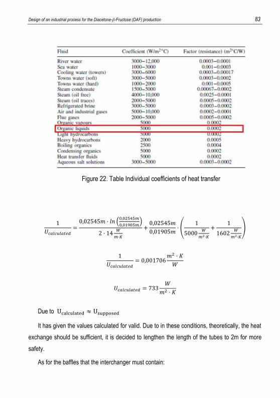
Design of an industrial process for the Diacetone-β-Fructose (DAF) production 83
Figure 22. Table Individual coefficients of heat transfer
1
𝑈𝑐𝑎𝑙𝑐𝑢𝑙𝑎𝑡𝑒𝑑=0,02545𝑚 · 𝑙𝑛 (
0,02545𝑚
0,01905𝑚)
2 · 14𝑊
𝑚·𝐾
+0,02545𝑚
0,01905𝑚· (
1
5000𝑊
𝑚2·𝐾
+1
1602𝑊
𝑚2·𝐾
)
1
𝑈𝑐𝑎𝑙𝑐𝑢𝑙𝑎𝑡𝑒𝑑= 0,001706
𝑚2 · 𝐾
𝑊
𝑈𝑐𝑎𝑙𝑐𝑢𝑙𝑎𝑡𝑒𝑑 = 733𝑊
𝑚2 · 𝐾
Due to Ucalculated ≈ Usupposed
It has given the values calculated for valid. Due to in these conditions, theoretically, the heat
exchange should be sufficient, it is decided to lengthen the length of the tubes to 2m for more
safety.
As for the baffles that the interchanger must contain:
84 González Arias, Noelia
𝐸𝑑 = 0,45 · 𝐷𝑖𝑛𝑡,𝑐 = 0,45 · 0,48𝑚 = 0,22𝑚
𝐷𝑑 = 𝐷𝑖𝑛𝑡,𝑐 −1
16= 0,42𝑚
𝑁𝐵 =𝐿
𝐸𝑑=2 𝑚
0,22= 9 𝑏𝑎𝑓𝑓𝑙𝑒𝑠
Barometric column design
For the design of the barometric column, it has been born in mind that it is recommended that
in internal side it is kept a speed of the fluid of approximately 0.98 m/s.
Therefore, knowing the flow rate of liquid that must be removed of the column for to keep
constant the height of liquid, it is calculed its diameter:
𝑞 =𝑤
𝜌=
2,6 𝑘𝑔/𝑠
0,9 · 790 𝑘𝑔 𝐴𝑐.
𝑚3 + 0,1 · 1000 𝑘𝑔 𝐻2𝑂
𝑚3
= 3,2 · 10−3𝑚3
𝑠
𝑞 = 𝑣𝐻2𝑂 · 𝑆𝑐𝑜𝑙 = 𝑣𝐻2𝑂 ·𝜋 · 𝐷𝑐𝑜𝑙
2
4→ 𝐷𝑐𝑜𝑙 = √
𝑞 · 4
𝑣𝐻2𝑂 · 𝜋= √
3,2 · 10−3𝑚3
𝑠· 4
0,98𝑚
𝑠· 𝜋
= 0,065𝑚
As for the height of the column, following equation of Bernoulli:
𝑧1 +𝑃1𝜌 · 𝑔
+𝑣12
2 · 𝑔= 𝑧2 +
𝑃2𝜌 · 𝑔
+𝑣22
2 · 𝑔
Considering despicable the term of kinetic energy:
𝑧1 +𝑃1𝜌 · 𝑔
= 𝑧2 +𝑃2𝜌 · 𝑔
∆𝑧 =𝑃2 − 𝑃1𝜌 · 𝑔
=44572𝑃𝑎
(0,9 · 790 𝑘𝑔 𝐴𝑐.
𝑚3 + 0,1 · 1000 𝑘𝑔 𝐻2𝑂
𝑚3 ) · 9,8𝑚
𝑠2
= 5,6𝑚
Design of an industrial process for the Diacetone-β-Fructose (DAF) production 85
It is recommended to add an excess of height to the column of approximately 2,5ft (0,8m) to
assure that its low part is always plunged and that the air inlet is impossible. Therefore, a final
height of column is obtained of:
𝑧𝑐𝑜𝑙 = 5,6𝑚 + 0,8𝑚 = 6,4𝑚
CALCULATION OF THE TIMES OF OPERATION
Coolings
For the calculation of the necessary time to carry out the stages of cooling the following
procedure has followed:
1. To suppose a value of the global coefficient of heat transfer.
2. To calculate the area of contact that is had in every case. Due to that the coolant
circulates along the jacketed of the vessels, the area of contact has been calculated as
the lateral area of the tank that corresponds with the height of the liquid that exists in
his interior.
3. To calculate the total heat to extracting of the system.
4. To fix a temperature of entry of the coolant.
5. Since one works in discontinuously and the driving force of the heat exchange, the
difference of temperature between liquid and coolant, is decreasing, the calculations
are realized with an intermediate temperature of liquid between the initial and the
wished final.
6. Having in tells the section of step of the cooling fluid across the jacketed (0,05m2) and
that the speed of this one has to be of between 1,5-2 m/s, there is calculated the flow
of coolant maximum.
7. By means of the maximum flow rate, the final temperature of the coolant is calculated.
8. Finally, the heat flow that the coolant is capable of extracting can be calculated and, in
consequence, the total time needed to extract the wished heat.
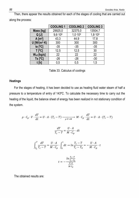
86 González Arias, Noelia
Then, there appear the results obtained for each of the stages of cooling that are carried out
along the process:
COOLING 1 COOLING 2 COOLING 3
Mass [kg] 29925,0 32375,0 13504,7
Q [J] 9,6·108 1,0·109 1,8·109
A [m2] 43,3 44,9 17,8
U [W/(m2·K) 300 300 300
te [ºC] -35 -35 -35
T [ºC] 12,5 12,5 30
Wref [kg/s] 22 22 22
Ts [ºC] -26 -26 -30
t [h] 0,5 0,5 1,5
Table 33. Calculus of coolings
Heatings
For the stages of heating, it has been decided to use as heating fluid water steam of half a
pressure to a temperature of entry of 143ºC. To calculate the necessary time to carry out the
heating of the liquid, the balance sheet of energy has been realized in not stationary condition of
the system.
𝜌 · 𝐶𝑝 · 𝑉 ·𝑑𝑇
𝑑𝑡= 𝑈 · 𝐴 · (𝑇𝑐 − 𝑇)
𝜌·𝑉=𝑀 → 𝑀 · 𝐶𝑝 ·
𝑑𝑇
𝑑𝑡= 𝑈 · 𝐴 · (𝑇𝑐 − 𝑇)
𝑑𝑇
𝑇𝑐 − 𝑇=𝑈 · 𝐴
𝑀 · 𝐶𝑝· 𝑑𝑡
∫𝑑𝑇
𝑇𝑐 − 𝑇=𝑈 · 𝐴
𝑀 · 𝐶𝑝· ∫ 𝑑𝑡
𝑡
0
𝑇
𝑇0
→ 𝑙𝑛𝑇𝑐 − 𝑇
𝑇𝑐 − 𝑇0= −
𝑈 · 𝐴
𝑀 · 𝐶𝑝· 𝑡
𝑡 = −𝑙𝑛
𝑇𝑐−𝑇
𝑇𝑐−𝑇0𝑈·𝐴
𝑀·𝐶𝑝
The obtained results are:
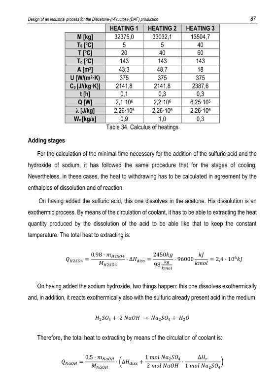
Design of an industrial process for the Diacetone-β-Fructose (DAF) production 87
HEATING 1 HEATING 2 HEATING 3
M [kg] 32375,0 33032,1 13504,7
T0 [ºC] 5 5 40
T [ºC] 20 40 60
Tc [ºC] 143 143 143
A [m2] 43,3 48,7 18
U [W/(m2·K) 375 375 375
Cp [J/(kg·K)] 2141,8 2141,8 2387,6
t [h] 0,1 0,3 0,3
Q [W] 2,1·106 2,2·106 6,25·105
λ [J/kg] 2,26·106 2,26·106 2,26·106
Wv [kg/s] 0,9 1,0 0,3
Table 34. Calculus of heatings
Adding stages
For the calculation of the minimal time necessary for the addition of the sulfuric acid and the
hydroxide of sodium, it has followed the same procedure that for the stages of cooling.
Nevertheless, in these cases, the heat to withdrawing has to be calculated in agreement by the
enthalpies of dissolution and of reaction.
On having added the sulfuric acid, this one dissolves in the acetone. His dissolution is an
exothermic process. By means of the circulation of coolant, it has to be able to extracting the heat
quantity produced by the dissolution of the acid to be able like that to keep the constant
temperature. The total heat to extracting is:
𝑄𝐻2𝑆𝑂4 =0,98 · 𝑚𝐻2𝑆𝑂4𝑀𝐻2𝑆𝑂4
· ∆𝐻𝑑𝑖𝑠𝑠 =2450𝑘𝑔
98𝑘𝑔
𝑘𝑚𝑜𝑙
· 96000𝑘𝐽
𝑘𝑚𝑜𝑙= 2,4 · 106𝑘𝐽
On having added the sodium hydroxide, two things happen: this one dissolves exothermically
and, in addition, it reacts exothermically also with the sulfuric already present acid in the medium.
𝐻2𝑆𝑂4 + 2 𝑁𝑎𝑂𝐻 → 𝑁𝑎2𝑆𝑂4 + 𝐻2𝑂
Therefore, the total heat to extracting by means of the circulation of coolant is:
𝑄𝑁𝑎𝑂𝐻 =0,5 · 𝑚𝑁𝑎𝑂𝐻𝑀𝑁𝑎𝑂𝐻
· (∆𝐻𝑑𝑖𝑠𝑠 +1 𝑚𝑜𝑙 𝑁𝑎2𝑆𝑂42 𝑚𝑜𝑙 𝑁𝑎𝑂𝐻
·∆𝐻𝑟
1 𝑚𝑜𝑙 𝑁𝑎2𝑆𝑂4)
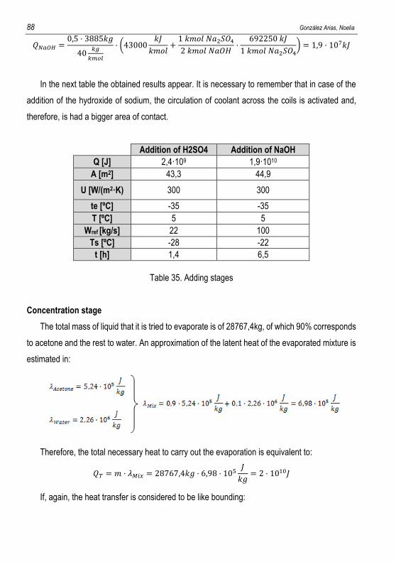
88 González Arias, Noelia
𝑄𝑁𝑎𝑂𝐻 =0,5 · 3885𝑘𝑔
40𝑘𝑔
𝑘𝑚𝑜𝑙
· (43000𝑘𝐽
𝑘𝑚𝑜𝑙+1 𝑘𝑚𝑜𝑙 𝑁𝑎2𝑆𝑂42 𝑘𝑚𝑜𝑙 𝑁𝑎𝑂𝐻
·692250 𝑘𝐽
1 𝑘𝑚𝑜𝑙 𝑁𝑎2𝑆𝑂4) = 1,9 · 107𝑘𝐽
In the next table the obtained results appear. It is necessary to remember that in case of the
addition of the hydroxide of sodium, the circulation of coolant across the coils is activated and,
therefore, is had a bigger area of contact.
Addition of H2SO4 Addition of NaOH
Q [J] 2,4·109 1,9·1010
A [m2] 43,3 44,9
U [W/(m2·K) 300 300
te [ºC] -35 -35
T [ºC] 5 5
Wref [kg/s] 22 100
Ts [ºC] -28 -22
t [h] 1,4 6,5
Table 35. Adding stages
Concentration stage
The total mass of liquid that it is tried to evaporate is of 28767,4kg, of which 90% corresponds
to acetone and the rest to water. An approximation of the latent heat of the evaporated mixture is
estimated in:
Therefore, the total necessary heat to carry out the evaporation is equivalent to:
𝑄𝑇 = 𝑚 · 𝜆𝑀𝑖𝑥 = 28767,4𝑘𝑔 · 6,98 · 105𝐽
𝑘𝑔= 2 · 1010𝐽
If, again, the heat transfer is considered to be like bounding:
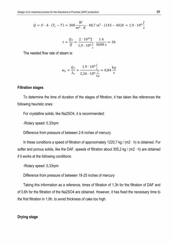
Design of an industrial process for the Diacetone-β-Fructose (DAF) production 89
𝑄 = 𝑈 · 𝐴 · (𝑇𝑐 − 𝑇) = 300𝑊
𝑚2 · 𝐾· 48,7 𝑚2 · (143 − 40)𝐾 = 1,9 · 106
𝐽
𝑠
𝑡 =𝑄𝑇𝑄=2 · 1010𝐽
1,9 · 106𝐽
𝑠
·1 ℎ
3600 𝑠= 3ℎ
The needed flow rate of steam is:
𝑤𝑣 =𝑄𝑇𝜆𝑣=
1,9 · 106𝐽
𝑠
2,26 · 106𝐽
𝑘𝑔
= 0,84𝑘𝑔
𝑠
Filtration stages
To determine the time of duration of the stages of filtration, it has taken like references the
following heuristic ones:
For crystalline solids, like Na2SO4, it is recommended:
-Rotary speed: 0,33rpm
Difference from pressure of between 2-6 inches of mercury
In these conditions a speed of filtration of approximately 1220,7 kg / (m2 · h) is obtained. For
softer and porous solids, like the DAF, speeds of filtration about 305,2 kg / (m2 · h) are obtained
if it works at the following conditions:
-Rotary speed: 0,33rpm
Difference from pressure of between 18-25 inches of mercury
Taking this information as a reference, times of filtration of 1,3h for the filtration of DAF and
of 0,6h for the filtration of the Na2SO4 are obtained. However, it has fixed the necessary time to
the first filtration in 1,6h, to avoid thickness of cake too high.
Drying stage
90 González Arias, Noelia
The dried consists of the elimination of present liquid in a wet solid by evaporation by means
of the contact of the solidwith a warm gas that provides the energy necessary for the evaporation.
It is therefore a stage of transfer of material and energy simultaneously.
The driving force of the process is the saturation humidity of the air in the conditions of
operation of the solvent to evaporating.
Since already it has been commented along the document, the speed of dried of the solid
presents two periods: a speed period of dried constant, where it limits the heat transfer, and a
period of variable speed, dependent on the solid - solvent system, where it limits the transfer of
material.
Due to:
The necessary information to determine the speed of dried of the DAF in the variable period
should decide experimentally.
The dryer turns and provokes the fall in waterfall of the wet solid, favoring the contact between
the phases and the transfer of material.
It has been decided to determine only the initial speed of dried of the solid to obtain an
estimation of the necessary time to carry out the stage.
In the period of constant speed, it is possible to calculate the speed of dried like:
By means of the use of the psychrometric diagram, the saturation temperature of the air in
hexane in the conditions of work and the speed of dried are decided.
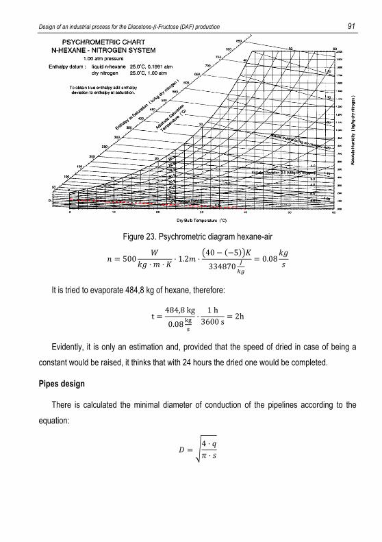
Design of an industrial process for the Diacetone-β-Fructose (DAF) production 91
Figure 23. Psychrometric diagram hexane-air
𝑛 = 500𝑊
𝑘𝑔 · 𝑚 · 𝐾· 1.2𝑚 ·
(40 − (−5))𝐾
334870𝐽
𝑘𝑔
= 0.08𝑘𝑔
𝑠
It is tried to evaporate 484,8 kg of hexane, therefore:
t =484,8 kg
0.08kg
s
·1 h
3600 s= 2h
Evidently, it is only an estimation and, provided that the speed of dried in case of being a
constant would be raised, it thinks that with 24 hours the dried one would be completed.
Pipes design
There is calculated the minimal diameter of conduction of the pipelines according to the
equation:
𝐷 = √4 · 𝑞
𝜋 · 𝑠
92 González Arias, Noelia
Speeds recommended for fluids in pipelines are used: for liquids for lines of conduction 1,5
m/s, for flows for gravity m/s and, both for air and for steam, 15 m/s.
Once obtained a value of diameter chooses as normalized diameter immediately top to the
calculated one.
As for the calculation of the minimal thickness, one resorts to the expression:
𝑒 =𝑃 · 𝑟
𝜎𝐿𝐸
All the calculated thicknesses are lower than the catalogued, so it will be chosen most adapted
according to the offer of the manufacturer.
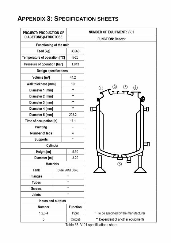
APPENDIX 3: SPECIFICATION SHEETS
PROJECT: PRODUCTION OF DIACETONE-β-FRUCTOSE
NUMBER OF EQUIPMENT: V-01
FUNCTION: Reactor
Functioning of the unit
Feed [kg] 36260
Temperature of operation [°C] 5-25
Pressure of operation [bar] 1.013
Design specifications
Volume [m3] 44.2
Wall thickness [mm] 10
Diameter 1 [mm] **
Diameter 2 [mm] **
Diameter 3 [mm] **
Diameter 4 [mm] **
Diameter 5 [mm] 203.2
Time of occupation [h] 17.1
Painting -
Number of legs 4
Supports *
Cylinder
Height [m] 5.50
Diameter [m] 3.20
Materials
Tank Steel AISI 304L
Flanges *
Tubes *
Screws *
Joints *
Inputs and outputs
Number Function
1,2,3,4 Input * To be specified by the manufacturer
5 Output ** Dependent of another equipments
Table 35. V-01 specifications sheet
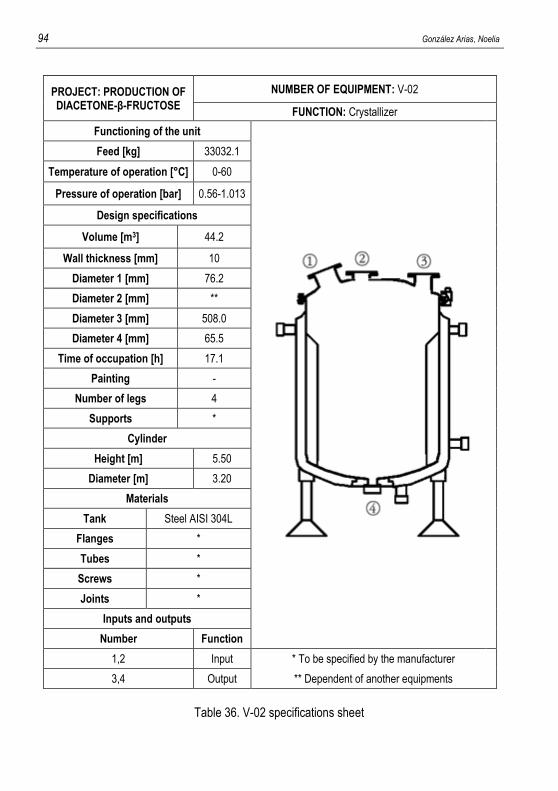
94 González Arias, Noelia
PROJECT: PRODUCTION OF DIACETONE-β-FRUCTOSE
NUMBER OF EQUIPMENT: V-02
FUNCTION: Crystallizer
Functioning of the unit
Feed [kg] 33032.1
Temperature of operation [°C] 0-60
Pressure of operation [bar] 0.56-1.013
Design specifications
Volume [m3] 44.2
Wall thickness [mm] 10
Diameter 1 [mm] 76.2
Diameter 2 [mm] **
Diameter 3 [mm] 508.0
Diameter 4 [mm] 65.5
Time of occupation [h] 17.1
Painting -
Number of legs 4
Supports *
Cylinder
Height [m] 5.50
Diameter [m] 3.20
Materials
Tank Steel AISI 304L
Flanges *
Tubes *
Screws *
Joints *
Inputs and outputs
Number Function
1,2 Input * To be specified by the manufacturer
3,4 Output ** Dependent of another equipments
Table 36. V-02 specifications sheet
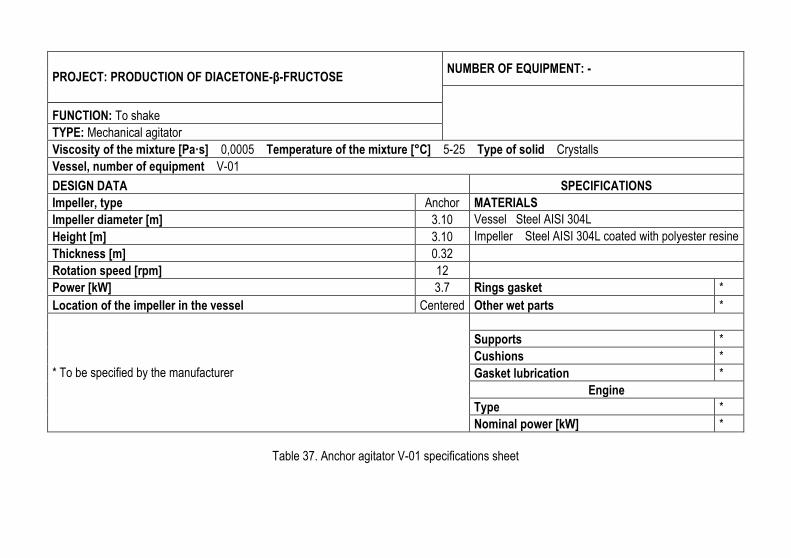
PROJECT: PRODUCTION OF DIACETONE-β-FRUCTOSE NUMBER OF EQUIPMENT: -
FUNCTION: To shake
TYPE: Mechanical agitator
Viscosity of the mixture [Pa·s] 0,0005 Temperature of the mixture [°C] 5-25 Type of solid Crystalls
Vessel, number of equipment V-01
DESIGN DATA SPECIFICATIONS
Impeller, type Anchor MATERIALS
Impeller diameter [m] 3.10 Vessel Steel AISI 304L
Height [m] 3.10 Impeller Steel AISI 304L coated with polyester resine
Thickness [m] 0.32
Rotation speed [rpm] 12
Power [kW] 3.7 Rings gasket *
Location of the impeller in the vessel Centered Other wet parts *
* To be specified by the manufacturer
Supports *
Cushions *
Gasket lubrication *
Engine
Type *
Nominal power [kW] *
Table 37. Anchor agitator V-01 specifications sheet
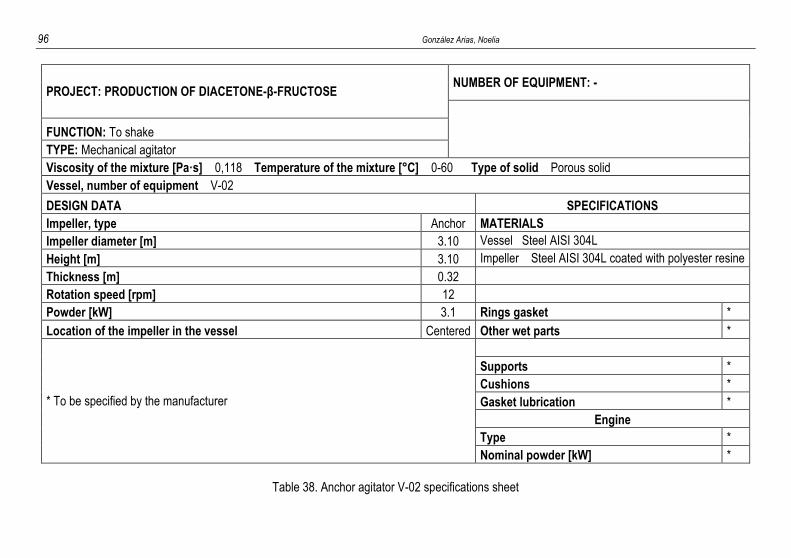
96 González Arias, Noelia
PROJECT: PRODUCTION OF DIACETONE-β-FRUCTOSE NUMBER OF EQUIPMENT: -
FUNCTION: To shake
TYPE: Mechanical agitator
Viscosity of the mixture [Pa·s] 0,118 Temperature of the mixture [°C] 0-60 Type of solid Porous solid
Vessel, number of equipment V-02
DESIGN DATA SPECIFICATIONS
Impeller, type Anchor MATERIALS
Impeller diameter [m] 3.10 Vessel Steel AISI 304L
Height [m] 3.10 Impeller Steel AISI 304L coated with polyester resine
Thickness [m] 0.32
Rotation speed [rpm] 12
Powder [kW] 3.1 Rings gasket *
Location of the impeller in the vessel Centered Other wet parts *
* To be specified by the manufacturer
Supports *
Cushions *
Gasket lubrication *
Engine
Type *
Nominal powder [kW] *
Table 38. Anchor agitator V-02 specifications sheet
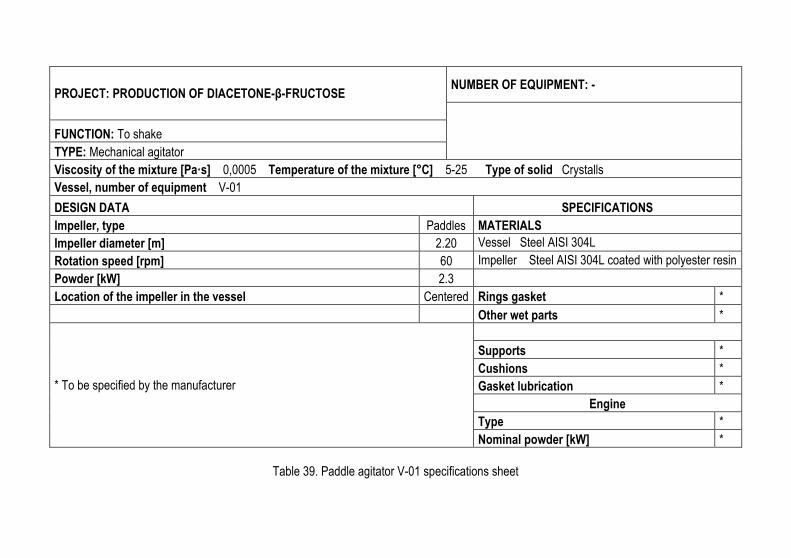
PROJECT: PRODUCTION OF DIACETONE-β-FRUCTOSE NUMBER OF EQUIPMENT: -
FUNCTION: To shake
TYPE: Mechanical agitator
Viscosity of the mixture [Pa·s] 0,0005 Temperature of the mixture [°C] 5-25 Type of solid Crystalls
Vessel, number of equipment V-01
DESIGN DATA SPECIFICATIONS
Impeller, type Paddles MATERIALS
Impeller diameter [m] 2.20 Vessel Steel AISI 304L
Rotation speed [rpm] 60 Impeller Steel AISI 304L coated with polyester resin
Powder [kW] 2.3
Location of the impeller in the vessel Centered Rings gasket *
Other wet parts *
* To be specified by the manufacturer
Supports *
Cushions *
Gasket lubrication *
Engine
Type *
Nominal powder [kW] *
Table 39. Paddle agitator V-01 specifications sheet
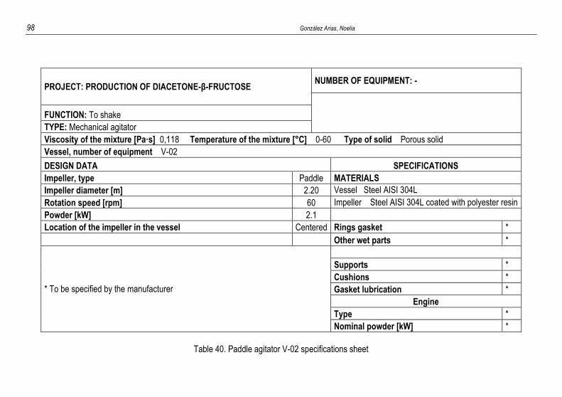
98 González Arias, Noelia
PROJECT: PRODUCTION OF DIACETONE-β-FRUCTOSE NUMBER OF EQUIPMENT: -
FUNCTION: To shake
TYPE: Mechanical agitator
Viscosity of the mixture [Pa·s] 0,118 Temperature of the mixture [°C] 0-60 Type of solid Porous solid
Vessel, number of equipment V-02
DESIGN DATA SPECIFICATIONS
Impeller, type Paddle MATERIALS
Impeller diameter [m] 2.20 Vessel Steel AISI 304L
Rotation speed [rpm] 60 Impeller Steel AISI 304L coated with polyester resin
Powder [kW] 2.1
Location of the impeller in the vessel Centered Rings gasket *
Other wet parts *
* To be specified by the manufacturer
Supports *
Cushions *
Gasket lubrication *
Engine
Type *
Nominal powder [kW] *
Table 40. Paddle agitator V-02 specifications sheet
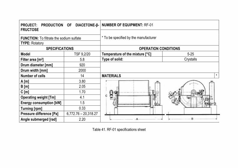
PROJECT: PRODUCTION OF DIACETONE-β-FRUCTOSE
NUMBER OF EQUIPMENT: RF-01
* To be specified by the manufacturer FUNCTION: To fíltrate the sodium sulfate
TYPE: Rotatory
SPECIFICATIONS OPERATION CONDITIONS
Model TSF 9,2/20 Temperature of the mixture [°C] 5-25
Filter area [m2] 5.8 Type of solid: Crystalls
Drum diameter [mm] 920
Drum width [mm] 2000
Number of cells 14 MATERIALS *
A [m] 3.80
B [m] 2.05
C [m] 1.70
Operating weight [Tm] 4.1
Energy consumption [kW] 1.5
Turning [rpm] 0.33
Pressure difference [Pa] 6,772.76 – 20,318.27
Angle submerged [rad] 2.20
Table 41. RF-01 specifications sheet
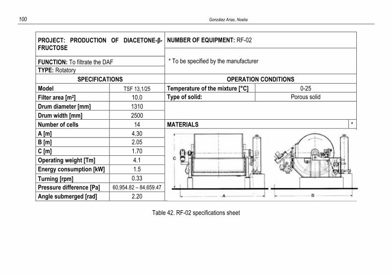
100 González Arias, Noelia
PROJECT: PRODUCTION OF DIACETONE-β-FRUCTOSE
NUMBER OF EQUIPMENT: RF-02
* To be specified by the manufacturer FUNCTION: To fíltrate the DAF
TYPE: Rotatory
SPECIFICATIONS OPERATION CONDITIONS
Model TSF 13,1/25 Temperature of the mixture [°C] 0-25
Filter area [m2] 10.0 Type of solid: Porous solid
Drum diameter [mm] 1310
Drum width [mm] 2500
Number of cells 14 MATERIALS *
A [m] 4.30
B [m] 2.05
C [m] 1.70
Operating weight [Tm] 4.1
Energy consumption [kW] 1.5
Turning [rpm] 0.33
Pressure difference [Pa] 60,954.82 – 84,659.47
Angle submerged [rad] 2.20
Table 42. RF-02 specifications sheet
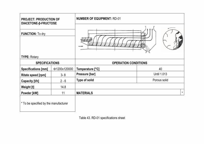
PROJECT: PRODUCTION OF DIACETONE-β-FRUCTOSE
NUMBER OF EQUIPMENT: RD-01
FUNCTION: To dry
TYPE: Rotary
SPECIFICATIONS OPERATION CONDITIONS
Specifications [mm] Փ1200x120000 Temperature [°C] 40
Ritate speed [rpm] 3- 8 Pressure [bar] Until 1.013
Capacity [t/h] 2 - 6 Type of solid Porous solid
Weight [t] 14.8
Powder [kW] 11 MATERIALS *
* To be specified by the manufacturer
Table 43. RD-01 specifications sheet

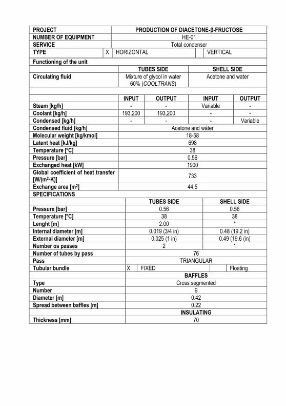
PROJECT PRODUCTION OF DIACETONE-β-FRUCTOSE
NUMBER OF EQUIPMENT HE-01
SERVICE Total condenser
TYPE X HORIZONTAL VERTICAL
Functioning of the unit
TUBES SIDE SHELL SIDE
Circulating fluid Mixture of glycol in water 60% (COOLTRANS)
Acetone and water
INPUT OUTPUT INPUT OUTPUT
Steam [kg/h] - - Variable -
Coolant [kg/h] 193,200 193,200 - -
Condensed [kg/h] - - - Variable
Condensed fluid [kg/h] Acetone and wáter
Molecular weight [kg/kmol] 18-58
Latent heat [kJ/kg] 698
Temperature [ºC] 38
Pressure [bar] 0.56
Exchanged heat [kW] 1900
Global coefficient of heat transfer [W/(m2·K)]
733
Exchange area [m2] 44.5
SPECIFICATIONS
TUBES SIDE SHELL SIDE
Pressure [bar] 0.56 0.56
Temperature [ºC] 38 38
Lenght [m] 2.00 *
Internal diameter [m] 0.019 (3/4 in) 0.48 (19.2 in)
External diameter [m] 0.025 (1 in) 0.49 (19.6 (in)
Number os passes 2 1
Number of tubes by pass 76
Pass TRIANGULAR
Tubular bundle X FIXED Floating
BAFFLES
Type Cross segmented
Number 9
Diameter [m] 0.42
Spread between baffles [m] 0.22
INSULATING
Thickness [mm] 70
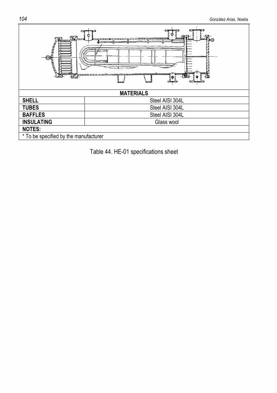
104 González Arias, Noelia
MATERIALS
SHELL Steel AISI 304L
TUBES Steel AISI 304L
BAFFLES Steel AISI 304L
INSULATING Glass wool
NOTES:
* To be specified by the manufacturer
Table 44. HE-01 specifications sheet