Embed Size (px)
Citation preview
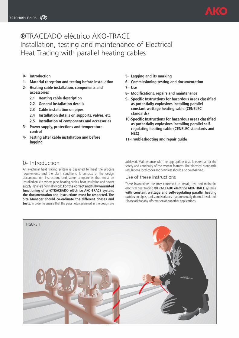
0- IntroductionAn electrical heat tracing system is designed to meet the process requirements and the plant conditions. It consists of the design documentation, instructions and some components that must be installed on site, where pipe, heating cables, heat insulation and power supply installers normally work. For the correct and fully warranted functioning of a ®TRACEADO eléctrico AKO-TRACE system, the documentation and instructions must be respected. The Site Manager should co-ordinate the different phases and tests, in order to ensure that the parameters planned in the design are
®TRACEADO eléctrico AKO-TRACE Installation, testing and maintenance of Electrical Heat Tracing with parallel heating cables
5- Lagging and its marking
6- Commissioning testing and documentation
7- Use
8- Modifications, repairs and maintenance
9- Specific Instructions for hazardous areas classified as potentially explosives installing parallel constant wattage heating cable (CENELEC standards)
10-Specific Instructions for hazardous areas classified as potentially explosives installing parallel self-regulating heating cable (CENELEC standards and NEC)
11-Troubleshooting and repair guide
FIGURE 1
GB7210H051 Ed.06
0- Introduction
1- Material reception and testing before installation
2- Heating cable installation, components and accessories
2.1 Heating cable description
2.2 General installation details
2.3 Cable installation on pipes
2.4 Installation details on supports, valves, etc.
2.5 Installation of components and accessories
3- Power supply, protections and temperature control
4- Testing after cable installation and before lagging
achieved. Maintenance with the appropriate tests is essential for the safety and continuity of the system features. The electrical standards, regulations, local codes and practices should also be observed.
Use of these instructions
These instructions are only conceived to install, test and maintain, electrical heat tracing ®TRACEADO eléctrico AKO-TRACE systems, with constant wattage and self-regulating parallel heating cables on pipes, tanks and surfaces that are usually thermal insulated. Please ask for any information about other applications.
Warnings!These instructions should be read and observed before to start the installation of the materials so that facility safety is not affected
Design documentation should be provided, for every electric heat trace ®TRACEADO eléctrico AKO-TRACE, system installation. If AKO or any authorised agent or distributor has not been the supplier of the design, the user or installer should design the system following AKO instructions and data sheet. Qualified personnel should carry out installation, tests and tracing system co-ordination, competent electricians should carry out connection to the power supply.
As in any other electric wiring system connected to the supply, an incorrect installation as well as damage caused to the cable or its accessories, allowing intrusion of moisture or corrosion may cause an electrical leakage, short circuit and the consequent failure risk.
Heating cables should not be installed in contact with wood or other combustible materials. If they were installed near these materials, it would be necessary to place a separation by means of a non-flammable material.
In order to avoid fire or an explosion in hazardous areas classified as potentially explosives, check in parallel constant wattage cables its maximum working temperature depending on the gas or vapour ignition temperature (item 9.2), in parallel self-regulating cables its maximum surface temperature depending on the gas or vapour ignition temperature.
In the parallel constant wattage heating cables the heating lengths should not be accessible. The two conductors of the heating cable should not be interconnected. This would cause a short-circuit.
The ends of each cable length should be sealed using the appropriate kit.
1.1 ReceptionMake sure that you have the latest version of the instructions and the project documentation and that you have received the materials you had ordered. Check the cables, the components, the thermostats and the accessories in order to make sure that their voltages, power and features are appropriate.
Check the aspect of the material you have received to detect any possible damage caused by transport. It is advisable to check the cable resistance or power and the insulation resistance of every cable reel. The minimum resistance should be 20 MW and it should be measured with an insulation resistance tester “Megger” at 1000 Vcc . Do not connect the heating cable while it is wound around the reel.
1.2 StorageKeep the materials in a clean and dry place until you need to install them on site, in order to minimise any possible mechanic damage. Storage temperature ranges from -15 ºC (5 ºF) up to +60 ºC (140 ºF) are accepted.
1.3 Tests before installationBefore starting the installation and in order to check that the design matches the construction conditions, it is essential to check and test each one of the following items.
1.3.1 Piping and fittings to be head traced
Make sure that the pipes and/or fittings installation is completed, the provisional supports has been removed after installing the definitive ones, the covering or painting is completely dry, and the pressure tests has been satisfactorily passed. Carrying out this type of works after having installed the cable can damage it.
Follow and check the planned heating cable routing, find the points where the power supply, the thermostats, the junction boxes and the
2.1 Heating cable description
AKO parallel heating cables both constant wattage or selfregulating, have a per-meter wattage output regardless of their length. These cables can be therefore supplied in reels, so that they can be cut-to length and finished on site.
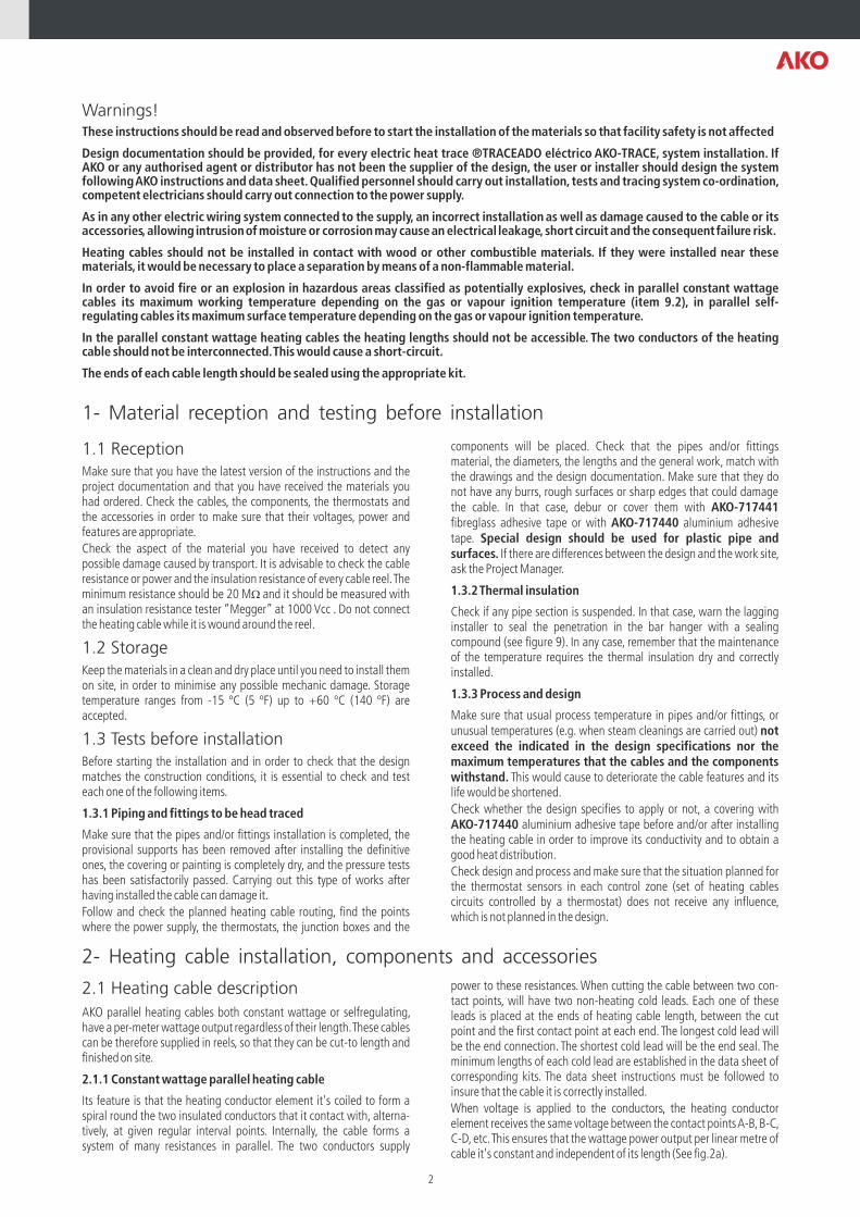
2.1.1 Constant wattage parallel heating cable
Its feature is that the heating conductor element it's coiled to form a spiral round the two insulated conductors that it contact with, alterna-tively, at given regular interval points. Internally, the cable forms a system of many resistances in parallel. The two conductors supply
components will be placed. Check that the pipes and/or fittings material, the diameters, the lengths and the general work, match with the drawings and the design documentation. Make sure that they do not have any burrs, rough surfaces or sharp edges that could damage the cable. In that case, debur or cover them with AKO-717441 fibreglass adhesive tape or with AKO-717440 aluminium adhesive tape. Special design should be used for plastic pipe and surfaces. If there are differences between the design and the work site, ask the Project Manager.
1.3.2 Thermal insulation
Check if any pipe section is suspended. In that case, warn the lagging installer to seal the penetration in the bar hanger with a sealing compound (see figure 9). In any case, remember that the maintenance of the temperature requires the thermal insulation dry and correctly installed.
1.3.3 Process and design
Make sure that usual process temperature in pipes and/or fittings, or unusual temperatures (e.g. when steam cleanings are carried out) not exceed the indicated in the design specifications nor the maximum temperatures that the cables and the components withstand. This would cause to deteriorate the cable features and its life would be shortened.
Check whether the design specifies to apply or not, a covering with AKO-717440 aluminium adhesive tape before and/or after installing the heating cable in order to improve its conductivity and to obtain a good heat distribution.
Check design and process and make sure that the situation planned for the thermostat sensors in each control zone (set of heating cables circuits controlled by a thermostat) does not receive any influence, which is not planned in the design.
power to these resistances. When cutting the cable between two con-tact points, will have two non-heating cold leads. Each one of these leads is placed at the ends of heating cable length, between the cut point and the first contact point at each end. The longest cold lead will be the end connection. The shortest cold lead will be the end seal. The minimum lengths of each cold lead are established in the data sheet of corresponding kits. The data sheet instructions must be followed to insure that the cable it is correctly installed.
When voltage is applied to the conductors, the heating conductor element receives the same voltage between the contact points A-B, B-C, C-D, etc. This ensures that the wattage power output per linear metre of cable it's constant and independent of its length (See fig.2a).
1- Material reception and testing before installation
2- Heating cable installation, components and accessories
2
Heatingconductor element
A C
D
A C
B D
Heating zone length Conductors
Connectioncold lead
Connectioncold lead
Coldend-seal
B
FIGURE 2a Constant wattage parallel cable
FIGURE 2b Self-regulating parallel cable
2.1.2 Self-regulating parallel heating cable
Its feature is that the heating element consists of a special polymer with a carbon mixture which acts as a semiconductor. When the temperature drops in the cable, numerous conducting lines are created in the poly-mer, decreasing its electrical resistance. The current through them
2.2 General installations details
The heating cable should be fixed in contact with the pipe or the surface to be heated. When constant wattage parallel cable is used, the connection cold lead should be the only part that passes through the lagging. Its function is supply power from the junction box to the heating zones of the cable. The connection cold lead should pass through the bottom part of the lagging to avoid the penetration of water or moisture in the lagging. It should be avoided that the lead is tense. Make sure that it allows any movement caused by vibrations or expansions.
On unwinding and installing the cable, we recommend:
AVOID any sharp edge, excessive mechanical efforts and do not twist, squash it, step on the cable, or put any load on it.
WE ADVISE to put the reel on a support in order to reduce the strength of unwinding the cable. Unwind the cable and extend it near the pipe avoiding any interference with supports or fittings. Do it in lengths and fix the cable on the pipe.
Add 1 m (3 ft) of cable length to each power end, splice, branch pipe or termination. Plan the supplementary lengths to compensate for anyhigher heat losses in the supports, valves and flanges or for spiralling as required by the system design documentation.
The cut cable ends on which the connection kit and end-seal have not
increase the heating cable power output. With this, it is possible to maintain the required temperature level. Inversely, when the cable temperature rise the conducting lines decrease, its electrical resistance rises and its power output decrease (see fig.2b).
been immediately installed should be protected from moisture, corrosion or any possible mechanical damage until the installation is completed (i.e. liquid silicone)
2.3 Cable installation on pipes
Make sure that the catalogue num. and features of the cable to be applied on each pipe length or equipment, match with the ones established by the design documentation.
Enough length of cold lead should be left in the power supply point for the connection to the box. Make sure that in constant wattage parallel heating cables, the heating length of the cable comes into contact with the pipe or surface to be heated. Fix the cable with AKO-717441 fibre glass adhesive tape AKO-717440 aluminium adhesive tape if a better heat transference were needed and if it were so specified. Do not use metallic fixing elements that could damage the cable or vinyl tapes or other kinds that could cause corrosion on the cables or the pipes.
Cable installation should be planned in order to facilitate any subsequent intervention, assembly and disassembly on the pipe and equipment (repair, valves exchange, etc.). Once the installation is completed and tested, the lagging and protection of pipe and/or equipment should be started following the design specifications as well as the item 5 of these instructions.
3
Cables should be uniformly distributed on the surface to be heated. Cables should not intersect or make contact. The distance between cables should be of at least 10 mm (0.4"). If these instructions are not observed, points and areas with higher temperatures will exist.
The bend radius should be of at least:
20 mm (0.82") in constant wattage cables
32 mm (1 ¼") in self-regulating cables
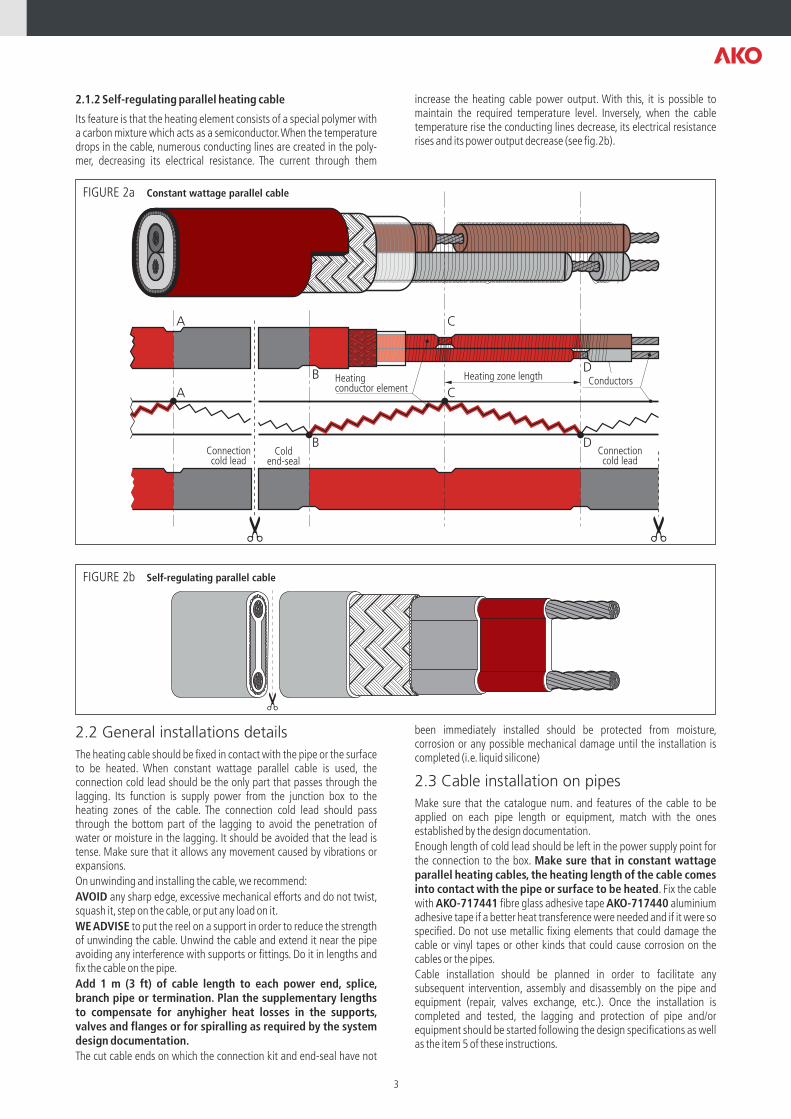
The heating cable should be applied straight along the pipe (one or more cables) or in spiral on the pipe only if it is specified in the ®TRACEADO eléctrico AKO-TRACE system documentation or as a result of the calculations.
2.3.1 Straight tracing
Cables should be installed according to figure 4 and avoiding the lower generatrix on the horizontal pipe. On vertical pipes, cables should be distributed equidistantly.
Install the heating cable in its position and fix it with AKO-717441 fibreglass adhesive tape rings every 300 mm (12") or less if necessary. See figure 5.
Adhesive tape
FIGURE 6
Fix adhesivetape afterspiralling Heating
cable length
Wind in theopposite direction
Fix adhesivetape afterspiralling
Heatingcable
Pipe
Fibreglassadhesive tape
Pipe lengthPitch
FIGURE 7
Adhesive tapeMax. 300 mm (12")
FIGURE 5
Heatinglength
Cold lead
In constantwattage
parallel cable
FIGURE 3
Uppergeneratrix
Lagging
45º 45º 45º
One heatingcable
Two heatingcable
Three heatingcable
Pipe
FIGURE 4
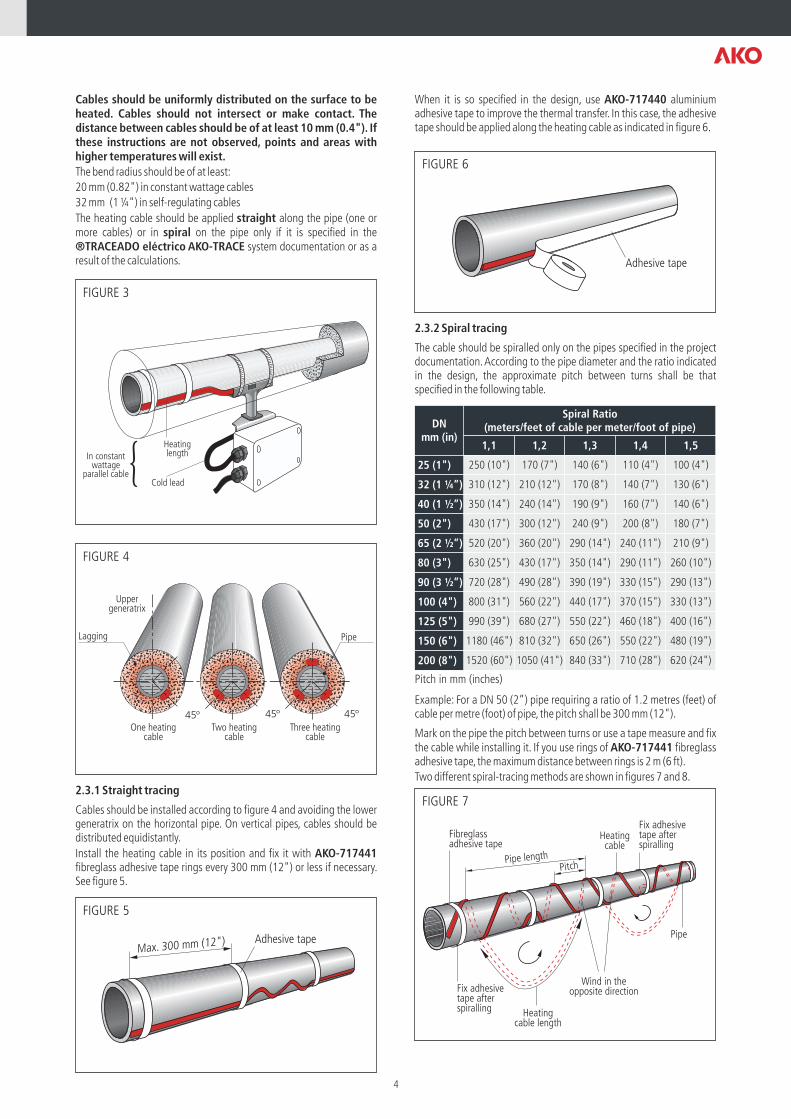
When it is so specified in the design, use AKO-717440 aluminium adhesive tape to improve the thermal transfer. In this case, the adhesive tape should be applied along the heating cable as indicated in figure 6.
2.3.2 Spiral tracing
The cable should be spiralled only on the pipes specified in the project documentation. According to the pipe diameter and the ratio indicated in the design, the approximate pitch between turns shall be that specified in the following table.
Example: For a DN 50 (2”) pipe requiring a ratio of 1.2 metres (feet) of cable per metre (foot) of pipe, the pitch shall be 300 mm (12").
Mark on the pipe the pitch between turns or use a tape measure and fix the cable while installing it. If you use rings of AKO-717441 fibreglass adhesive tape, the maximum distance between rings is 2 m (6 ft).
Two different spiral-tracing methods are shown in figures 7 and 8.
DNmm (in)
Spiral Ratio (meters/feet of cable per meter/foot of pipe)
1,1 1,2 1,3 1,4 1,5
25 (1") 250 (10") 170 (7") 140 (6") 110 (4") 100 (4")
32 (1 ¼”) 310 (12") 210 (12") 170 (8") 140 (7") 130 (6")
40 (1 ½”) 350 (14") 240 (14") 190 (9") 160 (7") 140 (6")
50 (2") 430 (17") 300 (12") 240 (9") 200 (8") 180 (7")
65 (2 ½”) 520 (20") 360 (20") 290 (14") 240 (11") 210 (9")
80 (3") 630 (25") 430 (17") 350 (14") 290 (11") 260 (10")
90 (3 ½”) 720 (28") 490 (28") 390 (19") 330 (15") 290 (13")
100 (4") 800 (31") 560 (22") 440 (17") 370 (15") 330 (13")
125 (5") 990 (39") 680 (27") 550 (22") 460 (18") 400 (16")
150 (6") 1180 (46") 810 (32") 650 (26") 550 (22") 480 (19")
200 (8") 1520 (60") 1050 (41") 840 (33") 710 (28") 620 (24")
Pitch in mm (inches)
4
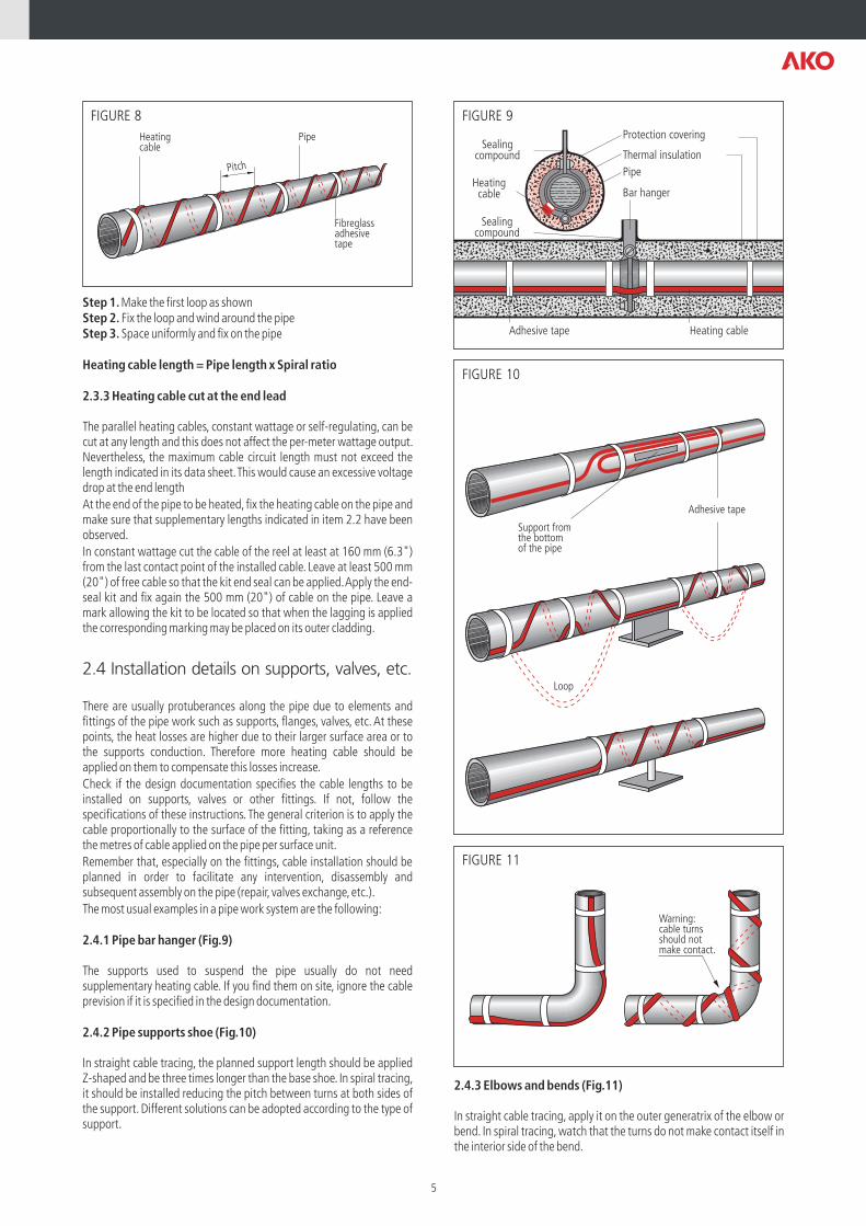
Sealingcompound
Protection covering
Thermal insulation
PipeHeatingcable Bar hanger
Heating cableAdhesive tape
Sealingcompound
FIGURE 9
Adhesive tape
Loop
Support fromthe bottomof the pipe
FIGURE 10
Warning:cable turnsshould notmake contact.
FIGURE 11
Heatingcable
Pitch
Pipe
Fibreglassadhesivetape
FIGURE 8
Step 1. Make the first loop as shownStep 2. Fix the loop and wind around the pipeStep 3. Space uniformly and fix on the pipe
Heating cable length = Pipe length x Spiral ratio
2.3.3 Heating cable cut at the end lead
The parallel heating cables, constant wattage or self-regulating, can be cut at any length and this does not affect the per-meter wattage output. Nevertheless, the maximum cable circuit length must not exceed the length indicated in its data sheet. This would cause an excessive voltage drop at the end length
At the end of the pipe to be heated, fix the heating cable on the pipe and make sure that supplementary lengths indicated in item 2.2 have been observed.
In constant wattage cut the cable of the reel at least at 160 mm (6.3") from the last contact point of the installed cable. Leave at least 500 mm (20") of free cable so that the kit end seal can be applied. Apply the end-seal kit and fix again the 500 mm (20") of cable on the pipe. Leave a mark allowing the kit to be located so that when the lagging is applied the corresponding marking may be placed on its outer cladding.
2.4 Installation details on supports, valves, etc.
There are usually protuberances along the pipe due to elements and fittings of the pipe work such as supports, flanges, valves, etc. At these points, the heat losses are higher due to their larger surface area or to the supports conduction. Therefore more heating cable should be applied on them to compensate this losses increase.
Check if the design documentation specifies the cable lengths to be installed on supports, valves or other fittings. If not, follow the specifications of these instructions. The general criterion is to apply the cable proportionally to the surface of the fitting, taking as a reference the metres of cable applied on the pipe per surface unit.
Remember that, especially on the fittings, cable installation should be planned in order to facilitate any intervention, disassembly and subsequent assembly on the pipe (repair, valves exchange, etc.).
The most usual examples in a pipe work system are the following:
2.4.1 Pipe bar hanger (Fig.9)
The supports used to suspend the pipe usually do not need supplementary heating cable. If you find them on site, ignore the cable prevision if it is specified in the design documentation.
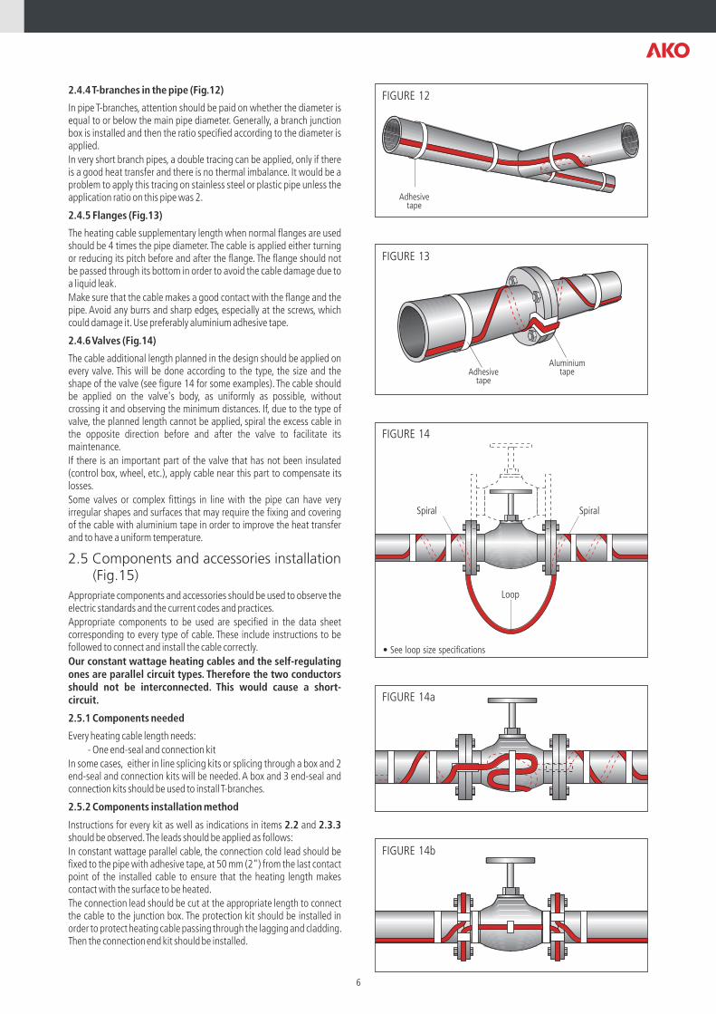
2.4.2 Pipe supports shoe (Fig.10)
In straight cable tracing, the planned support length should be applied Z-shaped and be three times longer than the base shoe. In spiral tracing, it should be installed reducing the pitch between turns at both sides of the support. Different solutions can be adopted according to the type of support.
2.4.3 Elbows and bends (Fig.11)
In straight cable tracing, apply it on the outer generatrix of the elbow or bend. In spiral tracing, watch that the turns do not make contact itself in the interior side of the bend.
5
Loop
SpiralSpiral
FIGURE 14
FIGURE 14a
FIGURE 14b
• See loop size specifications
Adhesivetape
FIGURE 12
AluminiumtapeAdhesive
tape
FIGURE 13
2.4.4 T-branches in the pipe (Fig.12)
In pipe T-branches, attention should be paid on whether the diameter is equal to or below the main pipe diameter. Generally, a branch junction box is installed and then the ratio specified according to the diameter is applied.
In very short branch pipes, a double tracing can be applied, only if there is a good heat transfer and there is no thermal imbalance. It would be a problem to apply this tracing on stainless steel or plastic pipe unless the application ratio on this pipe was 2.
2.4.5 Flanges (Fig.13)
The heating cable supplementary length when normal flanges are used should be 4 times the pipe diameter. The cable is applied either turning or reducing its pitch before and after the flange. The flange should not be passed through its bottom in order to avoid the cable damage due to a liquid leak.
Make sure that the cable makes a good contact with the flange and the pipe. Avoid any burrs and sharp edges, especially at the screws, which could damage it. Use preferably aluminium adhesive tape.
2.4.6 Valves (Fig.14)
The cable additional length planned in the design should be applied on every valve. This will be done according to the type, the size and the shape of the valve (see figure 14 for some examples). The cable should be applied on the valve's body, as uniformly as possible, without crossing it and observing the minimum distances. If, due to the type of valve, the planned length cannot be applied, spiral the excess cable in the opposite direction before and after the valve to facilitate its maintenance.
If there is an important part of the valve that has not been insulated (control box, wheel, etc.), apply cable near this part to compensate its losses.
Some valves or complex fittings in line with the pipe can have very irregular shapes and surfaces that may require the fixing and covering of the cable with aluminium tape in order to improve the heat transfer and to have a uniform temperature.
2.5 Components and accessories installation (Fig.15)
Appropriate components and accessories should be used to observe the electric standards and the current codes and practices.
Appropriate components to be used are specified in the data sheet corresponding to every type of cable. These include instructions to be followed to connect and install the cable correctly.
Our constant wattage heating cables and the self-regulating ones are parallel circuit types. Therefore the two conductors should not be interconnected. This would cause a short-circuit.
2.5.1 Components needed
Every heating cable length needs:
- One end-seal and connection kit
In some cases, either in line splicing kits or splicing through a box and 2 end-seal and connection kits will be needed. A box and 3 end-seal and connection kits should be used to install T-branches.
2.5.2 Components installation method
Instructions for every kit as well as indications in items 2.2 and 2.3.3 should be observed. The leads should be applied as follows:
In constant wattage parallel cable, the connection cold lead should be fixed to the pipe with adhesive tape, at 50 mm (2") from the last contact point of the installed cable to ensure that the heating length makes contact with the surface to be heated.
The connection lead should be cut at the appropriate length to connect the cable to the junction box. The protection kit should be installed in order to protect heating cable passing through the lagging and cladding. Then the connection end kit should be installed.
6

CABLE B
CABLE C
Supportto fix boxesto protection kit
Protection kitpassing throughthe laggingand cladding
FIGURE 15
End-seal of the kit
Signalling label
Fixingadhesivetape
Power supply
Connectionend of the kit
Identification label
Electric tracingwarning label
Ca
ble
ca
lefa
cto
r PARALELOd
e PO
TENCIA CO
NSTAN
TER
eferencia del cable: AK
O-712941
Núm
ero de fabricación: 000000Tem
peratura máxim
a exposición: 180 ° C
Voltaje: 230 V
Potencia: 10
W/m
± 7%P
royecto: RV-000000Tram
o calefactor: 1/C1/L1Tem
peratura de trabajo: 40 °C
Sis
tem
a A
KO•TRA
CE
CABLE C CABLE B CABLE A
Siliconprotector
Once end-seal kit has been installed at the cable end lead, It should be fixed with adhesive tape to the pipe in order for it to be subsequently covered by the lagging.
2.5.3 Junction boxes and other accessories
In a ®TRACEADO eléctrico AKO-TRACE system, junction boxes, supports to fix boxes to pipe, heating cables protection kits to passing through the lagging and cladding, adhesive tapes, and signalling and warning labels are usually used.
The box protection type or degree must be suitable for the environment where they are to be installed. On horizontal pipes and whenever possible, place the connection boxes below the pipe so that they are easily accessible and protected from possible hit, and where access is not normally necessary. Try not to place cable entries on top of the box and make sure that the glands are appropriate and have been correctly fixed. Unused entries shall be blanked off with suitable plugs. Close the junction boxes with their lids whenever access to them is not necessary.
Fixing supports to pipes can be used for junction boxes as well as for temperature controllers. Whenever it is possible, they should be in-stalled so that the lagging can be passed through its lower part in order to avoid the penetration of moisture. If it is not possible, remember to seal this point of the lagging.
Protection kits to pass through the lagging, mentioned in item 2.5.2, are used to protect the cable during the installation of the lagging. They
should be placed under the pipe to avoid the penetration of water, moisture or corrosion in the lagging.
The silicon protectors are used to protect the heating cables at sharp edges such as endplates of insulation cladding in flanges, valves, pumps, etc.
Clamps for fixing on pipes are included in the supports for fixing to pipes and in the protection kits to pass through the lagging. Clamps should not nip the heating cable because they would damage it.
Fixing adhesive tapes should be appropriate to withstand any temperature and not to cause corrosion in cables or in pipe and/or surfaces.
Warning labels are supplied. Attach them on the cladding to indicate that there is an electric tracing system under the lagging.
It is advisable that the installer marks with indelible identifying labels the heating cable length, junction boxes and thermostats. They should be labelled according to the nomenclature or code used in the design documentation. In heating cable lengths, labels should be placed in the connection lead next to the junction box. They should be applied according to instructions in item 5.
2.5.4 Typical system
See a detail of the typical installation with the most usual components and accessories in figure 15.
7
Heatingcable
Steel pipe Stainless steel pipe Plastic pipe
Sensor
Heatingcable
Sensor
Heatingcable
FIGURE 16
3- Power supply, protections and temperature control
Electric installation for the power supply of heating circuits should respect all standards, regulations and current codes of practice related to the environment and the facility features. Every heating circuit should be supplied by a power line with its corresponding protections, that should be identified according to the nomenclature or code used in the design documentation. If the heating cable has a protection metal braid, this braid shall be connected to the protective conductor (PE) of de plant installation.
3.1 Overcurrent protection
Electric protection should be in accordance with the project documentation and appropriate for the planned current in every circuit. It can be done either with circuit breaker switches or with fuses.
3.2 Residual current protection
In installations with heating cable without metal braid protection, a residual current device with a trip level of 30 mA should be used.
In installations with heating cable with metal braid protection, a residual current device with a trip level of 30 mA should be used in the following cases:
- In hazardous areas with a potentially explosive atmosphere
- In places with a risk of mechanical damages
- In environments with moisture or with a risk or corrosion
- Whenever frequent repairs or modifications are predicted
Other trip levels may also be used, all standards, regulations and current codes of practice should be observed.
3.2.1- Compliance with NEC requirements
According to Article 427 ground fault protection of equipment (GFPD) will be provided for electric heat tracing. Futhermore, IEEE 515 recommends a nominal 30 mA trip rating.
3.3 Protective earth
To obtain an efficient earth connection (with PE protection conductor element), use cable with a metal braid covering in installations with
- Plastic pipes
- Stainless steel pipes
- Painted pipes with bad electric conductivity
3.4 Temperature control
Temperature control allows us to save energy and makes the system work within its process and security limits.
3.4.0 General considerations
During the design process and according to temperatures given to carry out the project, normal working temperatures and maximum temper-atures that the system could reach should have been planned so that
they are within the security levels. Temperature limits that should have been taken into consideration are due to fluids, heating cables and their components, plastic pipe, thermal insulation, classified hazardous areas, etc. It should be also planned how to control and ensure this temperature.
The two usual methods to do so are:
3.4.1 Ambient temperature detection
During the design process, this method is usually specified for frost protection systems and/or to maintain temperature levels near to ambient or non-critical temperatures.
The maximum point temperature, with the system being stabilised at the sensor detection maximum ambient temperature, should not ex-ceed the maximum temperature allowed in any point of the system.
The temperature sensor should be installed in a place where minimum ambient temperatures can be predicted. It cannot be directly exposed either to the sunlight or to the influence of any thermal process or other plant temperatures.
3.4.2 Surface temperature detection
It is very usual that, due to process conditions, controlling pipe surface temperature is specified. In this case, the design documentation should define the control zones (group of heating cables circuits controlled by a thermostat) and the position of sensors on pipe.
The temperature sensor should be fixed parallel to the pipe and with a good thermal contact with it using binding clamps. Watch not to nip the heating cable. The maximum distance between the sensor and the heating cable, should be 80 mm (3") for steel pipe, 30 mm (1 ¼”) for stainless steel pipe, and in contact with the heating cable for plastic pipe. Different conditions specified in the design documentation should have priority over these general instructions.
If the thermostat's function is to protect from maximum exposure temperature disconnecting the cable (e.g. steam cleaning), the sensor should be fixed in the place where the highest temperatures are foreseen, taking into consideration that regulation should not exceed maximum working temperatures established for each cable.
When the sensor is installed on the pipe, it should be taken into consid-eration that it cannot receive any influence from heat bridges, such as supports, valves, pumps, etc., or from areas with temperatures different from the temperature to be maintained. The distance between these areas should not be less than 1 m (40"). If there exists more than one control zone, place the sensor on the correct pipe.
When the capillary or the cable of the thermostat sensor is installed, to pass through the lagging, precautions should be taken to avoid any damage. See picture 16.
8
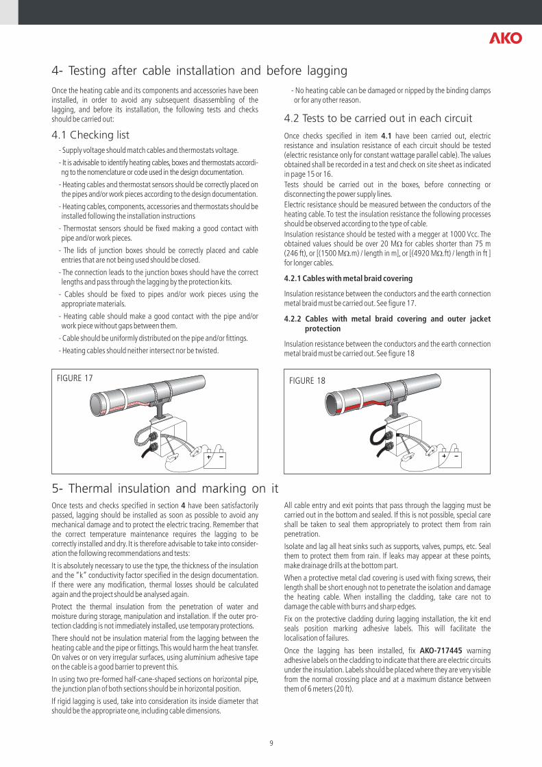
FIGURE 17 FIGURE 18
4- Testing after cable installation and before lagging
5- Thermal insulation and marking on it
Once the heating cable and its components and accessories have been installed, in order to avoid any subsequent disassembling of the lagging, and before its installation, the following tests and checks should be carried out:
4.1 Checking list
- Supply voltage should match cables and thermostats voltage.
- It is advisable to identify heating cables, boxes and thermostats accordi-ng to the nomenclature or code used in the design documentation.
- Heating cables and thermostat sensors should be correctly placed on the pipes and/or work pieces according to the design documentation.
- Heating cables, components, accessories and thermostats should be installed following the installation instructions
- Thermostat sensors should be fixed making a good contact with pipe and/or work pieces.
- The lids of junction boxes should be correctly placed and cable entries that are not being used should be closed.
- The connection leads to the junction boxes should have the correct lengths and pass through the lagging by the protection kits.
- Cables should be fixed to pipes and/or work pieces using the appropriate materials.
- Heating cable should make a good contact with the pipe and/or work piece without gaps between them.
- Cable should be uniformly distributed on the pipe and/or fittings.
- Heating cables should neither intersect nor be twisted.
- No heating cable can be damaged or nipped by the binding clamps or for any other reason.
4.2 Tests to be carried out in each circuit
Once checks specified in item 4.1 have been carried out, electric resistance and insulation resistance of each circuit should be tested (electric resistance only for constant wattage parallel cable). The values obtained shall be recorded in a test and check on site sheet as indicated in page 15 or 16.
Tests should be carried out in the boxes, before connecting or disconnecting the power supply lines.
Electric resistance should be measured between the conductors of the heating cable. To test the insulation resistance the following processes should be observed according to the type of cable.
Insulation resistance should be tested with a megger at 1000 Vcc. The obtained values should be over 20 MW for cables shorter than 75 m (246 ft), or [(1500 MW.m) / length in m], or [(4920 MW.ft) / length in ft ] for longer cables.
4.2.1 Cables with metal braid covering
Insulation resistance between the conductors and the earth connection metal braid must be carried out. See figure 17.
4.2.2 Cables with metal braid covering and outer jacket protection
Insulation resistance between the conductors and the earth connection metal braid must be carried out. See figure 18
All cable entry and exit points that pass through the lagging must be carried out in the bottom and sealed. If this is not possible, special care shall be taken to seal them appropriately to protect them from rain penetration.
Isolate and lag all heat sinks such as supports, valves, pumps, etc. Seal them to protect them from rain. If leaks may appear at these points, make drainage drills at the bottom part.
When a protective metal clad covering is used with fixing screws, their length shall be short enough not to penetrate the isolation and damage the heating cable. When installing the cladding, take care not to damage the cable with burrs and sharp edges.
Fix on the protective cladding during lagging installation, the kit end seals position marking adhesive labels. This will facilitate the localisation of failures.
Once the lagging has been installed, fix AKO-717445 warning adhesive labels on the cladding to indicate that there are electric circuits under the insulation. Labels should be placed where they are very visible from the normal crossing place and at a maximum distance between them of 6 meters (20 ft).
Once tests and checks specified in section 4 have been satisfactorily passed, lagging should be installed as soon as possible to avoid any mechanical damage and to protect the electric tracing. Remember that the correct temperature maintenance requires the lagging to be correctly installed and dry. It is therefore advisable to take into consider-ation the following recommendations and tests:
It is absolutely necessary to use the type, the thickness of the insulation and the “k” conductivity factor specified in the design documentation. If there were any modification, thermal losses should be calculated again and the project should be analysed again.
Protect the thermal insulation from the penetration of water and moisture during storage, manipulation and installation. If the outer pro-tection cladding is not immediately installed, use temporary protections.
There should not be insulation material from the lagging between the heating cable and the pipe or fittings. This would harm the heat transfer. On valves or on very irregular surfaces, using aluminium adhesive tape on the cable is a good barrier to prevent this.
In using two pre-formed half-cane-shaped sections on horizontal pipe, the junction plan of both sections should be in horizontal position.
If rigid lagging is used, take into consideration its inside diameter that should be the appropriate one, including cable dimensions.
9

6- Commissioning testing and documentation
7- Use
8- Modifications, repairs and maintenance
In this item the tests to be carried out in the commissioning until closing the construction site with its corresponding as built documentation are indicated.
6.1 Tests to be carried out
A visual inspection should be carried out to check that recommen-dations in item 5 have been observed. It should be specially observed that cables have not been damaged and that any possible rain penetration in the lagging has been sealed.
The tests indicated in item 4.2 shall be repeated for each circuit, following the same procedures. The values obtained must not be substantially different from the values recorded on testing this point and they shall also be recorded on the same on site test and check sheet. If any anomaly is detected, it shall be revised and modified if appropriate before commisioning.
6.2 Commissioning
1- Observations indicated in previous tests should be taken into con-sideration for the commissioning.
2- Before commissioning, make sure that the installation of the power supply observes all electric standards, regulations and current codes of practice.
3- Check identification or identify the circuit protections.
4- Set thermostats to around 5 ºC (41 ºF) above ambient temperature or pipe temperature at the moment of checking. Remember that once the circuits have been tested, thermostats shall be set to design temper-ature.
5- Switch on the general circuit breaker with individual circuit breakers off.
Any modification in the installation and/or process implies the review of the design documentation (project) associated to this facility, since its security can be affected by the modification.
It is important to apply the appropriate processes and to respect intervals, tests and checks when pipes, cables, lagging and other system components are modified, repaired or maintained so that a ®TRACEADO eléctrico AKO-TRACE system maintains long-lasting functional and safety characteristics.
8.1 Modifications
Any modification in the system, either of its dimensions or of its process conditions, implies that design of the modified part should be tested, checked and, if necessary, modified. To carry out the modification, indications and tests included in these instructions should be observed. All data should be recorded and modified in the system documentation.
8.2 Repairs
Pipe, work pieces and lagging as well as heating cables and accessories may need some repairs:
8.2.1 Pipes, work pieces and lagging
Disconnect the heating cable and protect it from any possible mechan-ical or thermal damage during the pipe, work pieces and lagging repair works. Check that it has been correctly installed according to these instructions at the end of the repair and fit the lagging again according to indications in item 5. When modification, repair or maintenance work is carried out, an inspection sheet like the one in page 15 or 16 should be filled in (use only the appropriate part of the sheet).
Make sure that electric protections work properly.
6- Start switching on each circuit and check:
- The correct functioning of its residual current protection
-Measure voltage and intensity
-Check the thermostat switches off correctly (if necessary, due to its slowness, lower its set point)
7- Once tests of the circuits in each heating control zone have been carried out, set the thermostat to the design temperature desired to be maintained (when ambient thermostats for frost protection systems are used, these shall be set to 6 ºC (43 ºF) unless another value is specified). Note down the set point temperature on the data sheet.
8- If convenient and possible, check that pipe and/or work piece reach the desired working temperature and that the thermostat works properly. Check the different temperatures in the heating control zone and reset the thermostat if necessary.
9- The obtained values should be recorded according to indications in item 6.3.
6.3 Documentation
The data obtained in items 4.2, 6.1 and 6.2 should be recorded in test and check on site sheets as indicated in page 15 or 16. These sheets can be included with the as built documentation of the construction site closing. This documentation should be given to the user, who should have it for any possible modification, repair and maintenance in pipe, or any subsequent incident.
Data or values in units demanded should be recorded in test and check on site sheets.
As process modification are included:
-Maximum operating process temperature.
-Maximum temperature at which the cable may be exposed (steam cleaning, etc.).
8.2.2 Heating cables
As in every electric installation, a damaged cable may facilitate the penetration of moisture or corrosion that may cause a short-circuit, with the resulting fire risk. The damaged cable should be immediately re-placed. Before doing it, it is important to analyse the cause of the failure so that the fault may be corrected and avoided in the future.
A heating cable should be repaired with original AKO kits and compo-nents according to their included instructions. The damaged cable length should be cut and replaced with a new cable length using the splicing system specified for each type of cable.
8.3 Maintenance
It is advisable to carry out periodic inspections at not more than two years intervals. However, they should be carried out more frequently when working, safety, corrosion, moisture, etc., conditions require it. In frost protection installations and in those ones whose correct operation is closely related to weather conditions, it is recommended to carry out inspections every year, before these conditions take place. An inspection should be carried out after any repair or maintenance work in pipe, work piece or lagging.
Check regularly the correct operation of electric protections and ther-mostats, as well as the identification labels indicated in item 2.5.3. These labels should be legible, and replaced when necessary.
The inspection process should be the same as the one specified in item 6. It should be also recorded in inspection sheets as the one indicated in page 15 or 16, (use only the appropriate part of the sheet).
10
9-Specific instructions for hazardous areas classified as potentially explosive using constant wattage parallel heating cables (CENELEC standards)
If a ®TRACEADO eléctrico AKO-TRACE system, or a part of it, is installed or has to pass through a hazardous classified area as poten-tially explosive atmosphere, in addition previous items indications the instructions and tests specified in this item should be strictly ensured.
Electric or tracing installers who take part in the work should be qual-ified, competent and fully conversant with safety standards to work in hazardous areas classified as potentially explosive atmospheres.
9.1 At the materials reception
Check that heating cables, their end seal and connection kits, boxes, thermostats, glands and other electric material are certified and appro-priate for the area and temperature classification.
The most commonly used protection methods are:
- Heating cables with their end seal and connection kits:“e”
- Junction boxes: “e”
- Thermostats or temperature control: “d”, “e” or “i”
- Glands: “e” or “d”
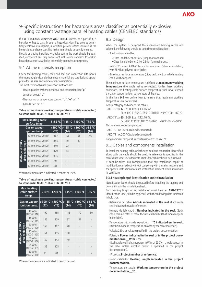
Table of maximum working temperatures (cable connected) to standards EN 60079-0 and EN 60079-7
When no temperature is indicated, it cannot be used.
Table of maximum working temperatures (cable connected) to standards EN 60079-0 and EN 60079-7
When no temperature is indicated, it cannot be used.
9.2 Design
When the system is designed the appropriate heating cables are selected, the following should be taken into consideration:
- The location should be:
ŸClass I and the Zones 1 or 2 (for gas or vapours)ŸClass II and the Zones 21 or 22 (for flammable dust)
- AKO-701xx and AKO-711xx cables materials: Silicone insulation, with FEP fluorpolymer outer jacket.
- Maximum surface temperature (pipe, tank, etc.) on which heating cable will be applied.
The maximum surface temperature is defined as maximum working temperature (the cable being connected). Under these working conditions, the heating cable surface temperature shall never exceed the gas or vapour ignition temperature of the area.
In the item 9.4 we define how to ensure that maximum working temperatures are not exceed.
Group, category and code of the cables:
-AKO-701xx: II 2 GD Ex e IIC T3..T6 Gb
Ex tb IIIC T185 °C..T85 °C Db IP66 -40 ºC £ Ta £ +60 ºC
-AKO-711xx: II 2 GD Ex e IIC T2..T6 Gb
Ex tb IIIC T210 °C..T85 °C Db IP66 -40 ºC £ Ta £ +60 ºC
Maximum exposure temperature:
-AKO-701xx: 180 °C (cable disconnected)
-AKO-711xx: 200 °C (cable disconnected)
Range ambient temperature for its use: -40 °C to +60 °C
9.3 Cables and components installation
To install the heating cable, only the end-seal and connection kit certified along with the cable should be used. Its reference is specified in the cables data sheet. Included instructions for each kit should be observed.
It must be taken into consideration that any installation, repair or modification carried out without complying with these instructions and the specific instructions for each installation element would invalidate its certificate.
9.3.1 Heating length identification on site installation
Identification labels should be placed before installing the lagging and before filling in the installation sheet.
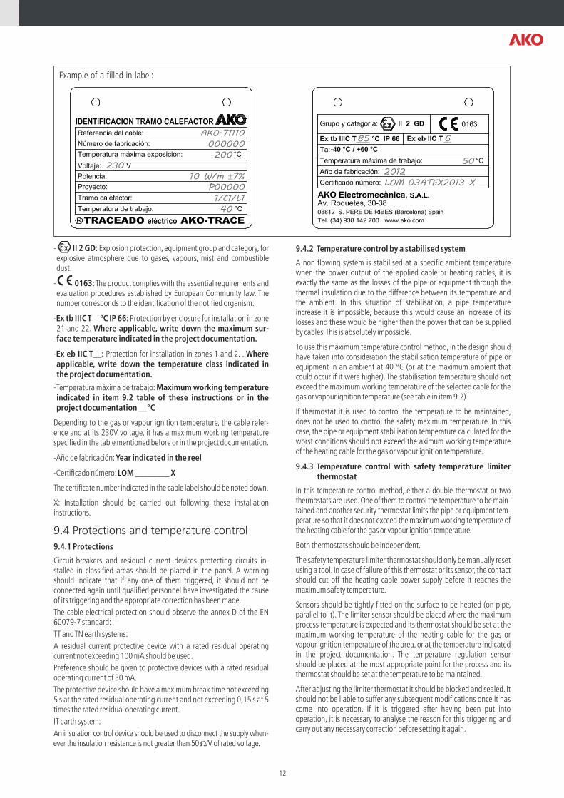
Each heating length of an installation must have an AKO-71751 identification label, filled in by pencil, with the following data indicated in bold type:
-Referencia del cable: AKO-As indicated in the reel. (Each cable reel indicates the cable reference).
-Número de fabricación: Number indicated in the reel. (Each cable reel indicates its manufacture number (Nº) that should appear in the label).
-Temperatura máxima de exposición: __ºC indicated en the reel. (It is the maximum temperature allowed by the cable materials).
-Voltaje: 230 V or voltage specified in the project documentation.
-Potencia: Power indicated in the reel or in the project docu-mentation in __W/m ±7%.(Each cable reel indicates power in W/m at 230 V. It should appear in the label unless another power is specified in the project documentation).
-Proyecto: Project number or reference.
-Tramo calefactor: Heating length indicated in the project documentation.
-Temperatura de trabajo: Working temperature in the project documentation __ºC.
Max. heating cable surface temp.
T185 ºC T135 ºC T100 ºC T85 ºC
Gas or vapourignition temp.
>200 ºC(T3)
>135 ºC(T4)
>100 ºC(T5)
>85 ºC(T6)
Pot
enc
10 W/m (AKO-70110) 167 108 65 46
15 W/m (AKO-70115) 155 90 40 -
20 W/m (AKO-70120) 140 72 - -
25 W/m (AKO-70125) 129 53 - -
30 W/m (AKO-70130) 115 - - -
35 W/m (AKO-70135) 98 - - -
40 W/m (AKO-70140) 84 - - -
Max. heating cable surface
temp.T210 ºC T200 ºC T135 ºC T100 ºC T85 ºC
Gas or vapourignition temp.
>300 ºC(T2)
>200 ºC(T3)
>135 ºC(T4)
>100 ºC(T5)
>85 ºC(T6)
10 W/m(AKO-71110)
190 185 113 70 50
15 W/m (AKO-71115)
185 179 97 49 -
20 W/m (AKO-71120)
168 162 78 - -
25 W/m (AKO-71125)
161 155 60 - -
30 W/m (AKO-71130)
150 143 40 - -
35 W/m (AKO-71135)
132 125 - - -
50 W/m (AKO-71150)
91 82 - - -
Wat
tag
e at
230 V
d
/on c
able
typ
e
Wat
tag
e at
230 V
d
/on c
able
typ
e
11
Example of a filled in label:
- II 2 GD: Explosion protection, equipment group and category, for explosive atmosphere due to gases, vapours, mist and combustible dust.
- 0163: The product complies with the essential requirements and evaluation procedures established by European Community law. The number corresponds to the identification of the notified organism.
-Ex tb IIIC T__ºC IP 66: Protection by enclosure for installation in zone 21 and 22. Where applicable, write down the maximum sur-face temperature indicated in the project documentation.
-Ex eb IIC T__: Protection for installation in zones 1 and 2. . Where applicable, write down the temperature class indicated in the project documentation.
-Temperatura máxima de trabajo: Maximum working temperature indicated in item 9.2 table of these instructions or in the project documentation __°C
Depending to the gas or vapour ignition temperature, the cable refer-ence and at its 230V voltage, it has a maximum working temperature specified in the table mentioned before or in the project documentation.
-Año de fabricación: Year indicated in the reel
-Certificado número: LOM ________ X
The certificate number indicated in the cable label should be noted down.
X: Installation should be carried out following these installation instructions.
9.4 Protections and temperature control
9.4.1 Protections
Circuit-breakers and residual current devices protecting circuits in-stalled in classified areas should be placed in the panel. A warning should indicate that if any one of them triggered, it should not be connected again until qualified personnel have investigated the cause of its triggering and the appropriate correction has been made.
The cable electrical protection should observe the annex D of the EN 60079-7 standard:
TT and TN earth systems:
A residual current protective device with a rated residual operating current not exceeding 100 mA should be used.
Preference should be given to protective devices with a rated residual operating current of 30 mA.
The protective device should have a maximum break time not exceeding 5 s at the rated residual operating current and not exceeding 0,15 s at 5 times the rated residual operating current.
IT earth system:
An insulation control device should be used to disconnect the supply when-ever the insulation resistance is not greater than 50 W/V of rated voltage.
9.4.2 Temperature control by a stabilised system
A non flowing system is stabilised at a specific ambient temperature when the power output of the applied cable or heating cables, it is exactly the same as the losses of the pipe or equipment through the thermal insulation due to the difference between its temperature and the ambient. In this situation of stabilisation, a pipe temperature increase it is impossible, because this would cause an increase of its losses and these would be higher than the power that can be supplied by cables. This is absolutely impossible.
To use this maximum temperature control method, in the design should have taken into consideration the stabilisation temperature of pipe or equipment in an ambient at 40 °C (or at the maximum ambient that could occur if it were higher). The stabilisation temperature should not exceed the maximum working temperature of the selected cable for the gas or vapour ignition temperature (see table in item 9.2)
If thermostat it is used to control the temperature to be maintained, does not be used to control the safety maximum temperature. In this case, the pipe or equipment stabilisation temperature calculated for the worst conditions should not exceed the aximum working temperature of the heating cable for the gas or vapour ignition temperature.
9.4.3 Temperature control with safety temperature limiter thermostat
In this temperature control method, either a double thermostat or two thermostats are used. One of them to control the temperature to be main-tained and another security thermostat limits the pipe or equipment tem-perature so that it does not exceed the maximum working temperature of the heating cable for the gas or vapour ignition temperature.
Both thermostats should be independent.
The safety temperature limiter thermostat should only be manually reset using a tool. In case of failure of this thermostat or its sensor, the contact should cut off the heating cable power supply before it reaches the maximum safety temperature.
Sensors should be tightly fitted on the surface to be heated (on pipe, parallel to it). The limiter sensor should be placed where the maximum process temperature is expected and its thermostat should be set at the maximum working temperature of the heating cable for the gas or vapour ignition temperature of the area, or at the temperature indicated in the project documentation. The temperature regulation sensor should be placed at the most appropriate point for the process and its thermostat should be set at the temperature to be maintained.
After adjusting the limiter thermostat it should be blocked and sealed. It should not be liable to suffer any subsequent modifications once it has come into operation. If it is triggered after having been put into operation, it is necessary to analyse the reason for this triggering and carry out any necessary correction before setting it again.
85 6
50
LOM 03ATEX2013 X2012
AKO-71110
000000200
40
23010 W/m ±7%
P00000
1/C1/L1
12
9.5 Test and check on site sheet
In the test and check on site sheet at page 15, the location in item 1 and the identification labels in item 9 should be filled in.
9.6 Modifications and repairs
When in addition to indicated in items 8.1 and 8.2, there were modifi-cations as, hazardous area classification, dangerous materials that are being handled, process or dimensional conditions, design conditions should be checked. Carry out any necessary modifications and record all them in the project documentation with all new checking that have
been carried out
Any repair should be carried out according to these instructions and the specific instructions with which every component has been certified. When this is not possible, replace the damaged component with a new one.
When in the initial design and installation, cables have been covered and fitted on the valves and complex on line fittings, with aluminium adhesive tape to reduce surface temperatures and make them uniform, the same criteria should be followed whenever a repair is carried out. An inspection should be carried out so that the repair is correct and working conditions are the same as in the initial design.
10- Specific instructions for hazardous areas classified as potentially explosive using self-regulating parallel heating cables (CENELEC standards and NEC)
If a ®TRACEADO eléctrico AKO-TRACE, system, or a part of it, is installed or has to pass through a hazardous classified area as poten-tially explosive atmosphere, in addition previous items indica-tions the instructions and tests specified in this item should be strictly ensured.
Electric or tracing installers who take part in the work should be qualified, competent and fully conversant with safety standards to work in hazardous areas classified as potentially explosive atmospheres.
10.1 At the materials reception
Check that heating cables, their end seal and connection kits, boxes, thermostats, glands and other electric material are certified and appro-priate for the area and temperature classification.
The most commonly used protection methods according to CENELEC are:
- Heating cables with their end seal and connection kits: “e”
- Junction boxes: “e”
- Thermostats or temperature control: “d”, “e” or “i”
- Glands: “e” or “d”
10.2 Design
When the system is designed the appropriate heating cables are selected, the following should be taken into consideration:
-The location should be:
-The heating cable maximum surface temperature (temperature class) never should be higher than gas or vapour ignition temperature of the classified area.
10.3 Cables and components installation
To install the heating cable, only the end-seal and connection kit certi-fied along with the cable should be used. Its reference is specified in the cables data sheet. Included instructions for each kit should be observed.
It must be taken into consideration that any installation, repair or mod-ification carried out without complying with these instructions and the specific instructions for each installation element would invalidate its certificate.
10.4 Protections and temperature control
10.4.1 Protections
Circuit-breakers and residual current devices protecting circuits in-stalled in classified areas should be placed in the panel. A warning should indicate that if any one of them triggered, it should not be connected again until qualified personnel have investigated the cause of its triggering and the appropriate correction has been made.
According to CENELEC the cable electrical protection should observe the annex D of the EN 60079-7 standard:
TT and TN earth systems:
A residual current protective device with a rated residual operating current not exceeding 100 mA should be used.
Preference should be given to protective devices with a rated residual operating current of 30 mA.
The protective device should have a maximum break time not exceeding 5 s at the rated residual operating current and not exceeding 0,15 s at 5 times the rated residual operating current.
IT earth system:
An insulation control device should be used to disconnect the supply whenever the insulation resistance is not greater than 50 W/V of rated voltage.
10.4.2 Temperature control by a stabilised system
A non flowing system is stabilised at a specific ambient temperature when the power output of the applied cable or heating cables, it is exactly the same as the losses of the pipe or equipment through the thermal insulation due to the difference between its temperature and the ambient. In this situation of stabilisation, a pipe temperature increase it is impossible, because this would cause an increase of its losses and these would be higher than the power that can be supplied by cables. This is absolutely impossible.
To use this maximum temperature control method, in the design should have taken into consideration the stabilisation temperature of pipe or equipment in an ambient at 40 °C (104 ºF) (or at the maximum ambient that could occur if it were higher). The stabilisation temperature should not exceed the maximum working temperature of the selected cable for the gas or vapour ignition temperature.
If thermostat it is used to control the temperature to be maintained, does not be used to control the safety maximum temperature. In this case, the pipe or equipment stabilisation temperature calculated for the worst conditions should not exceed the maximum working temperature of the heating cable for the gas or vapour ignition temperature.
10.4.3 Temperature control with safety temperature limiter thermostat
In this temperature control method, either a double thermostat or two thermostats are used. One of them to control the temperature to be main-tained and another security thermostat limits the pipe or equipment temperature so that it does not exceed the maximum working temperature of the heating cable for the gas or vapour ignition temperature.
Both thermostats should be independent.
The safety temperature limiter thermostat should only be manually reset using a tool. In case of failure of this thermostat or its sensor, the contact should cut off the heating cable power supply before it reaches the maximum safety temperature.
The temperature regulation sensor should be placed at the most appropriate point for the process and its thermostat should be set at the temperature to be maintained. Sensor should be fitted on the surface to be heated (on pipes, parallel to it).
For gas or vapors For flammable dust
CENELEC Class I, Zones 1 or 2 Class II, Zones 21 or 22
NEC Class I Div.2 or Class I Zone 2 -
13
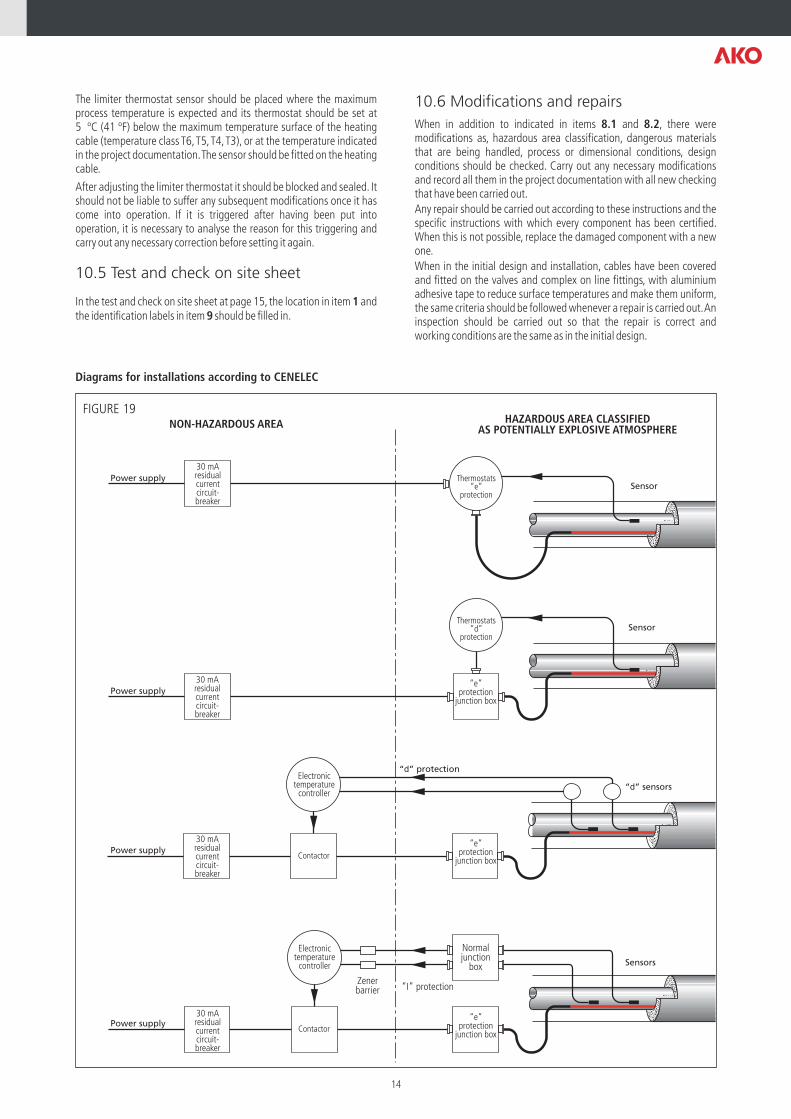
Normaljunction
box
Power supplyContactor
Zenerbarrier “I” protection
Power supplyContactor
Electronictemperature
controller
Electronictemperature
controller
“d” protection
“d” sensors
“e”protection
junction box
“e”protection
junction box
“e”protection
junction box
Power supply
Power supply
30 mAresidualcurrentcircuit-breaker
30 mAresidualcurrentcircuit-breaker
30 mAresidualcurrentcircuit-breaker
30 mAresidualcurrentcircuit-breaker
Sensor
Sensors
Thermostats“e”
protection
Thermostats“d”
protection
NON-HAZARDOUS AREA HAZARDOUS AREA CLASSIFIEDAS POTENTIALLY EXPLOSIVE ATMOSPHERE
Sensor
FIGURE 19
The limiter thermostat sensor should be placed where the maximum process temperature is expected and its thermostat should be set at 5 ºC (41 ºF) below the maximum temperature surface of the heating cable (temperature class T6, T5, T4, T3), or at the temperature indicated in the project documentation. The sensor should be fitted on the heating cable.
After adjusting the limiter thermostat it should be blocked and sealed. It should not be liable to suffer any subsequent modifications once it has come into operation. If it is triggered after having been put into operation, it is necessary to analyse the reason for this triggering and carry out any necessary correction before setting it again.
10.5 Test and check on site sheet
In the test and check on site sheet at page 15, the location in item 1 and the identification labels in item 9 should be filled in.
10.6 Modifications and repairs
When in addition to indicated in items 8.1 and 8.2, there were modifications as, hazardous area classification, dangerous materials that are being handled, process or dimensional conditions, design conditions should be checked. Carry out any necessary modifications and record all them in the project documentation with all new checking that have been carried out.
Any repair should be carried out according to these instructions and the specific instructions with which every component has been certified. When this is not possible, replace the damaged component with a new one.
When in the initial design and installation, cables have been covered and fitted on the valves and complex on line fittings, with aluminium adhesive tape to reduce surface temperatures and make them uniform, the same criteria should be followed whenever a repair is carried out. An inspection should be carried out so that the repair is correct and working conditions are the same as in the initial design.
Diagrams for installations according to CENELEC
14
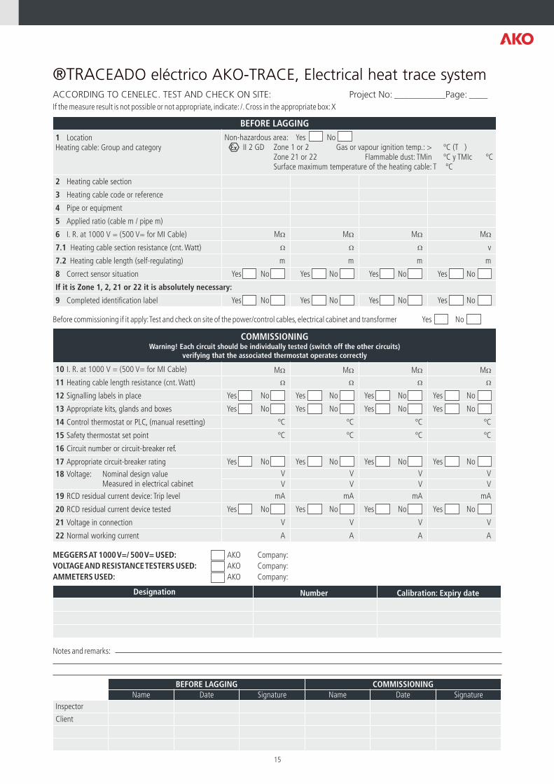
®TRACEADO eléctrico AKO-TRACE, Electrical heat trace systemACCORDING TO CENELEC. TEST AND CHECK ON SITE: Project No: ___________Page: ____
If the measure result is not possible or not appropriate, indicate: /. Cross in the appropriate box: X
Before commissioning if it apply: Test and check on site of the power/control cables, electrical cabinet and transformer
MEGGERS AT 1000 V=/ 500 V= USED:
VOLTAGE AND RESISTANCE TESTERS USED: AKO Company:
AMMETERS USED: AKO Company:
Notes and remarks:
Yes No
AKO Company:
Designation Number Calibration: Expiry date
BEFORE LAGGING COMMISSIONINGName Date Signature Name Date Signature
Inspector
Client
BEFORE LAGGING
1 LocationHeating cable: Group and category
Non-hazardous area: Yes NoII 2 GD Zone 1 or 2 Gas or vapour ignition temp.: > ºC (T )
Zone 21 or 22 Flammable dust: TMin ºC y TMIc ºCSurface maximum temperature of the heating cable: T ºC
2 Heating cable section
3 Heating cable code or reference
4 Pipe or equipment
5 Applied ratio (cable m / pipe m)
6 I. R. at 1000 V = (500 V= for MI Cable) MW MW MW MW
7.1 Heating cable section resistance (cnt. Watt) W W W v
7.2 Heating cable length (self-regulating) m m m m
8 Correct sensor situation Yes No Yes No Yes No Yes No
If it is Zone 1, 2, 21 or 22 it is absolutely necessary:
9 Completed identification label Yes No Yes No Yes No Yes No
15
COMMISSIONINGWarning! Each circuit should be individually tested (switch off the other circuits)
verifying that the associated thermostat operates correctly
10 I. R. at 1000 V = (500 V= for MI Cable) MW MW MW MW
11 Heating cable length resistance (cnt. Watt) W W W W
12 Signalling labels in place Yes No Yes No Yes No Yes No
13 Appropriate kits, glands and boxes Yes No Yes No Yes No Yes No
14 Control thermostat or PLC, (manual resetting) ºC ºC ºC ºC
15 Safety thermostat set point ºC ºC ºC ºC
16 Circuit number or circuit-breaker ref.
17 Appropriate circuit-breaker rating Yes No Yes No Yes No Yes No
18 Voltage: Nominal design value Measured in electrical cabinet
V V V V
V V V V
19 RCD residual current device: Trip level mA mA mA mA
20 RCD residual current device tested Yes No Yes No Yes No Yes No
21 Voltage in connection V V V V
22 Normal working current A A A A
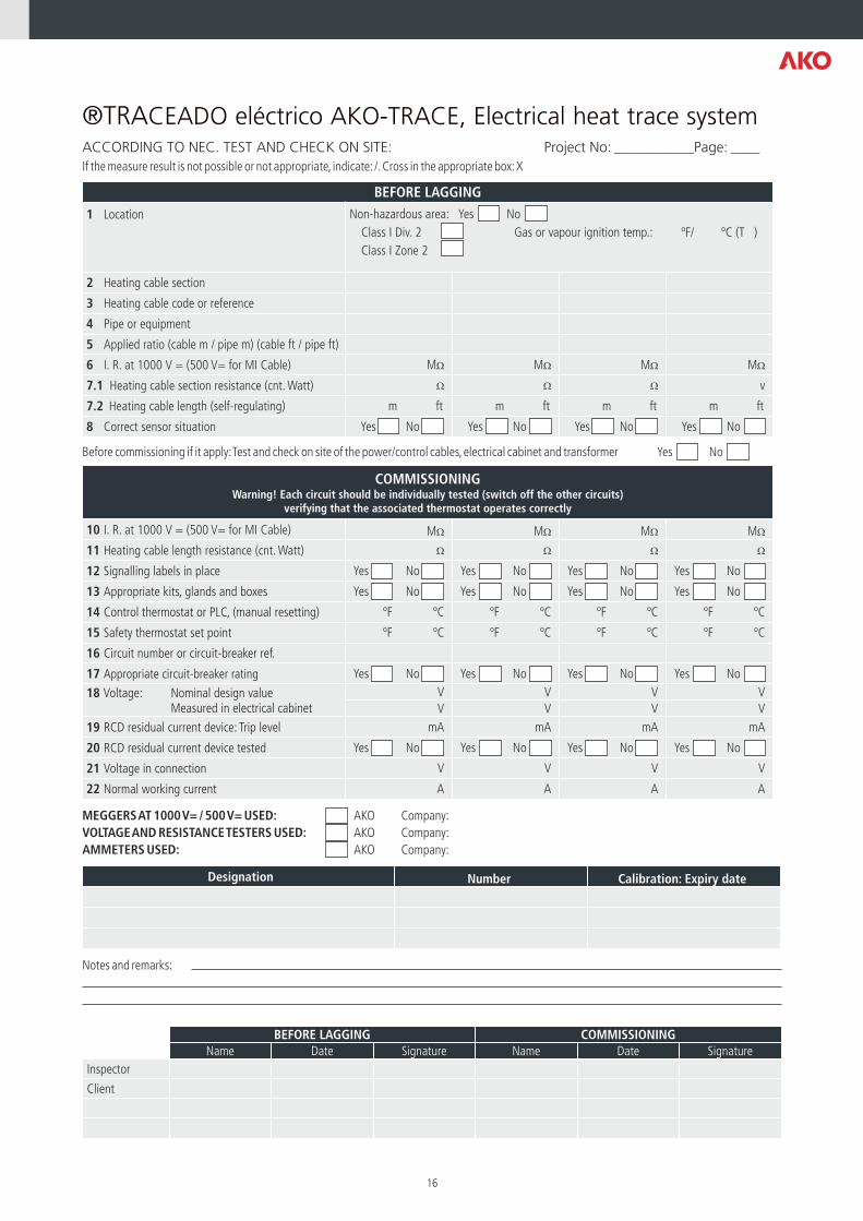
®TRACEADO eléctrico AKO-TRACE, Electrical heat trace systemACCORDING TO NEC. TEST AND CHECK ON SITE: Project No: ___________Page: ____
If the measure result is not possible or not appropriate, indicate: /. Cross in the appropriate box: X
Before commissioning if it apply: Test and check on site of the power/control cables, electrical cabinet and transformer
MEGGERS AT 1000 V= / 500 V= USED:
VOLTAGE AND RESISTANCE TESTERS USED: AKO Company:
AMMETERS USED: AKO Company:
Notes and remarks:
Yes No
AKO Company:
COMMISSIONINGWarning! Each circuit should be individually tested (switch off the other circuits)
verifying that the associated thermostat operates correctly
10 I. R. at 1000 V = (500 V= for MI Cable) MW MW MW MW
11 Heating cable length resistance (cnt. Watt) W W W W
12 Signalling labels in place Yes No Yes No Yes No Yes No
13 Appropriate kits, glands and boxes Yes No Yes No Yes No Yes No
14 Control thermostat or PLC, (manual resetting) ºF ºC ºF ºC ºF ºC ºF ºC
15 Safety thermostat set point ºF ºC ºF ºC ºF ºC ºF ºC
16 Circuit number or circuit-breaker ref.
17 Appropriate circuit-breaker rating Yes No Yes No Yes No Yes No
18 Voltage: Nominal design value Measured in electrical cabinet
V V V V
V V V V
19 RCD residual current device: Trip level mA mA mA mA
20 RCD residual current device tested Yes No Yes No Yes No Yes No
21 Voltage in connection V V V V
22 Normal working current A A A A
Designation Number Calibration: Expiry date
BEFORE LAGGING COMMISSIONINGName Date Signature Name Date Signature
Inspector
Client
BEFORE LAGGING
1 Location Non-hazardous area: Yes No
Class I Div. 2 Gas or vapour ignition temp.: ºF/ ºC (T )
Class I Zone 2
2 Heating cable section
3 Heating cable code or reference
4 Pipe or equipment
5 Applied ratio (cable m / pipe m) (cable ft / pipe ft)
6 I. R. at 1000 V = (500 V= for MI Cable) MW MW MW MW
7.1 Heating cable resistance (cnt. Watt)section W W W v
7.2 Heating cable length (self-regulating) m ft m ft m ft m ft
8 Correct sensor situation Yes No Yes No Yes No Yes No
16
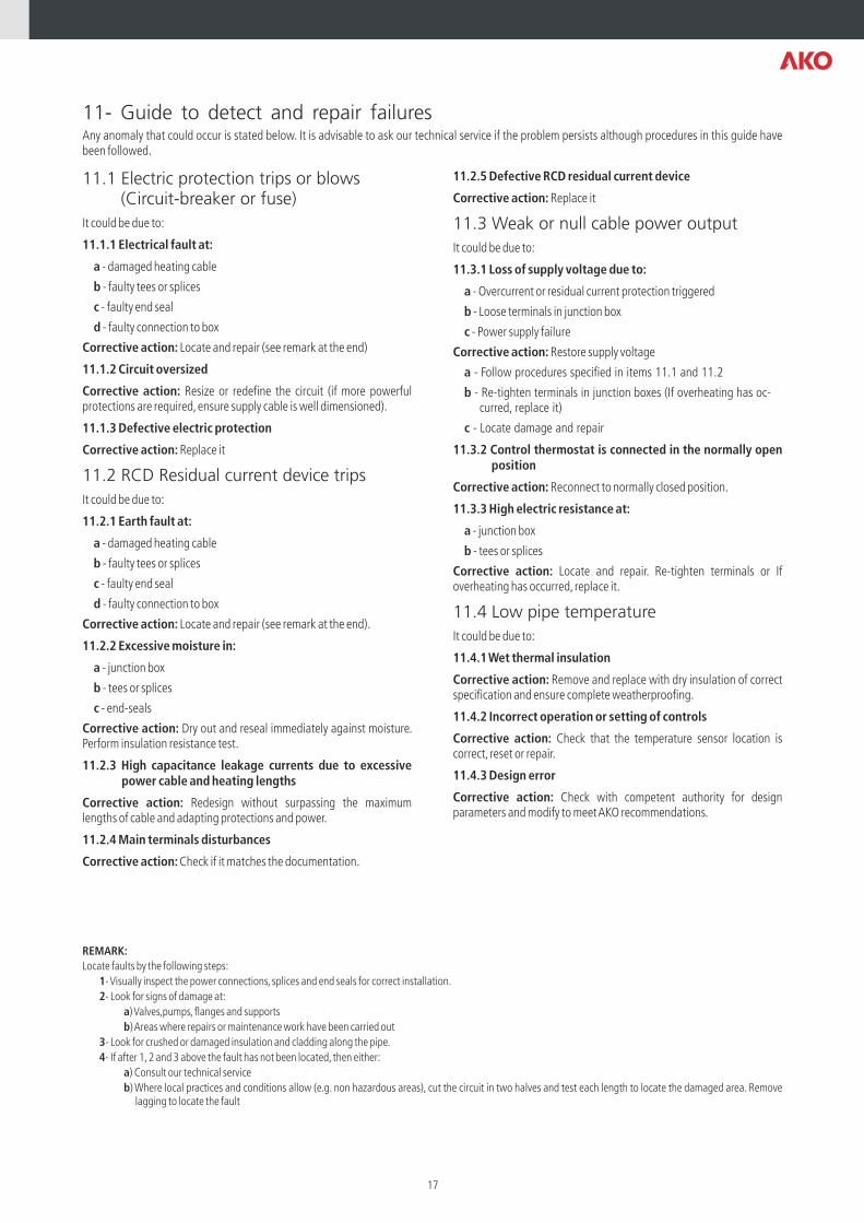
11- Guide to detect and repair failuresAny anomaly that could occur is stated below. It is advisable to ask our technical service if the problem persists although procedures in this guide have been followed.
11.1 Electric protection trips or blows (Circuit-breaker or fuse)
It could be due to:
11.1.1 Electrical fault at:
a - damaged heating cable
b - faulty tees or splices
c - faulty end seal
d - faulty connection to box
Corrective action: Locate and repair (see remark at the end)
11.1.2 Circuit oversized
Corrective action: Resize or redefine the circuit (if more powerful protections are required, ensure supply cable is well dimensioned).
11.1.3 Defective electric protection
Corrective action: Replace it
11.2 RCD Residual current device trips
It could be due to:
11.2.1 Earth fault at:
a - damaged heating cable
b - faulty tees or splices
c - faulty end seal
d - faulty connection to box
Corrective action: Locate and repair (see remark at the end).
11.2.2 Excessive moisture in:
a - junction box
b - tees or splices
c - end-seals
Corrective action: Dry out and reseal immediately against moisture. Perform insulation resistance test.
11.2.3 High capacitance leakage currents due to excessive power cable and heating lengths
Corrective action: Redesign without surpassing the maximum lengths of cable and adapting protections and power.
11.2.4 Main terminals disturbances
Corrective action: Check if it matches the documentation.
11.2.5 Defective RCD residual current device
Corrective action: Replace it
11.3 Weak or null cable power output
It could be due to:
11.3.1 Loss of supply voltage due to:
a - Overcurrent or residual current protection triggered
b - Loose terminals in junction box
c - Power supply failure
Corrective action: Restore supply voltage
a - Follow procedures specified in items 11.1 and 11.2
b - Re-tighten terminals in junction boxes (If overheating has oc-curred, replace it)
c - Locate damage and repair
11.3.2 Control thermostat is connected in the normally open position
Corrective action: Reconnect to normally closed position.
11.3.3 High electric resistance at:
a - junction box
b - tees or splices
Corrective action: Locate and repair. Re-tighten terminals or If overheating has occurred, replace it.
11.4 Low pipe temperature
It could be due to:
11.4.1 Wet thermal insulation
Corrective action: Remove and replace with dry insulation of correct specification and ensure complete weatherproofing.
11.4.2 Incorrect operation or setting of controls
Corrective action: Check that the temperature sensor location is correct, reset or repair.
11.4.3 Design error
Corrective action: Check with competent authority for design parameters and modify to meet AKO recommendations.
REMARK:
Locate faults by the following steps:
1- Visually inspect the power connections, splices and end seals for correct installation.
2- Look for signs of damage at:
a) Valves,pumps, flanges and supports
b) Areas where repairs or maintenance work have been carried out
3- Look for crushed or damaged insulation and cladding along the pipe.
4- If after 1, 2 and 3 above the fault has not been located, then either:
a) Consult our technical service
b) Where local practices and conditions allow (e.g. non hazardous areas), cut the circuit in two halves and test each length to locate the damaged area. Remove lagging to locate the fault
17
357210051 R
EV
.05 2014
AKO ELECTROMECÀNICA, S.A.L.We reserve the right to supply materials that might vary slightly to those described in our Technical Sheets. Updated information is available on our website
Av. Roquetes, 30-38 | 08812 Sant Pere de Ribes | Barcelona | EspañaTel. (34) 938 142 700 | Fax (34) 938 934 054 | e-mail: [email protected] | www.ako.com