Embed Size (px)
DESCRIPTION
hj
Citation preview
1..
..
Ultrasonic TOFD TechniqueUltrasonic TOFD Technique
Prepared by : Prepared by :
MJMJ Inspection Consultancy, Malaysia Inspection Consultancy, Malaysia
Tel : 60 - 7 - 5568-907 Tel : 60 - 7 - 5568-907
Fax : 60 - 7 - 5568-918Fax : 60 - 7 - 5568-918
Email : [email protected] : [email protected]
Rev .03-Sept
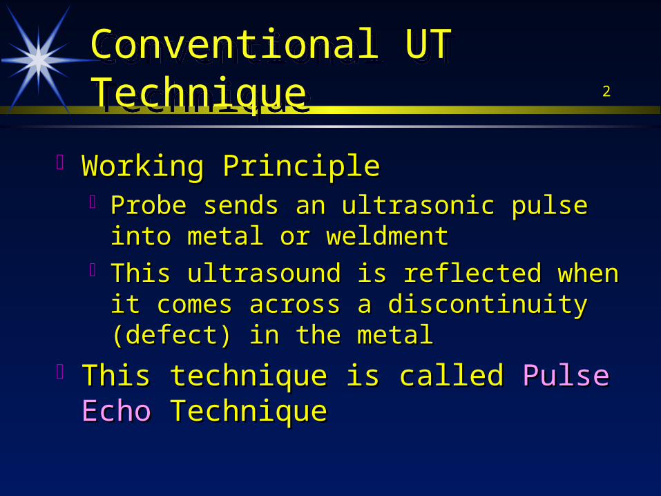
2Conventional UT TechniqueConventional UT Technique
Working PrincipleWorking Principle Probe sends an ultrasonic pulse into metal or Probe sends an ultrasonic pulse into metal or
weldmentweldment This ultrasound is reflected when it comes across This ultrasound is reflected when it comes across
a discontinuity (defect) in the metala discontinuity (defect) in the metal This technique is called This technique is called Pulse EchoPulse Echo Technique Technique
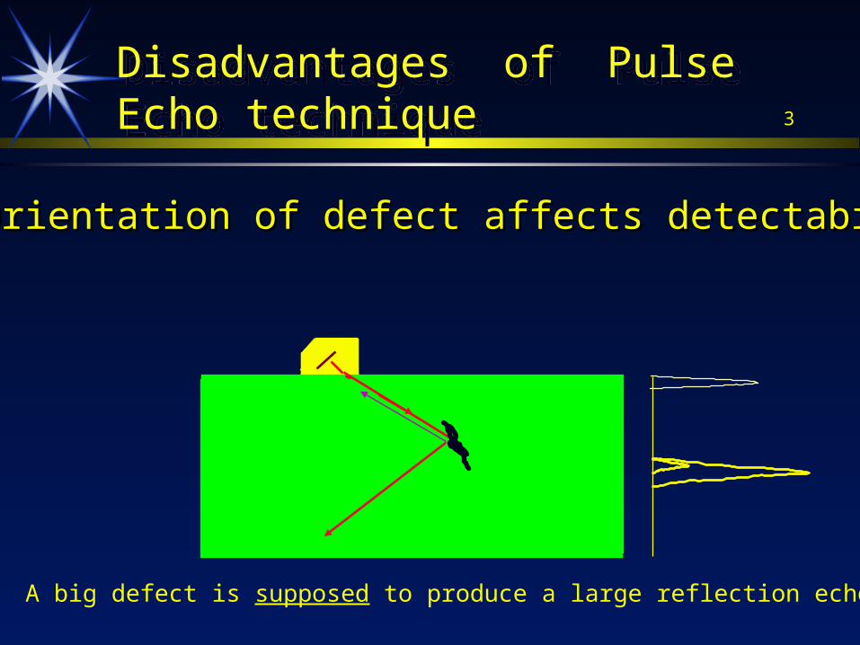
3Disadvantages of Pulse Echo techniqueDisadvantages of Pulse Echo technique
1. 1. Orientation of defect affects detectability.Orientation of defect affects detectability.
A big defect is supposed to produce a large reflection echo
4Disadvantages of Pulse Echo techniqueDisadvantages of Pulse Echo technique
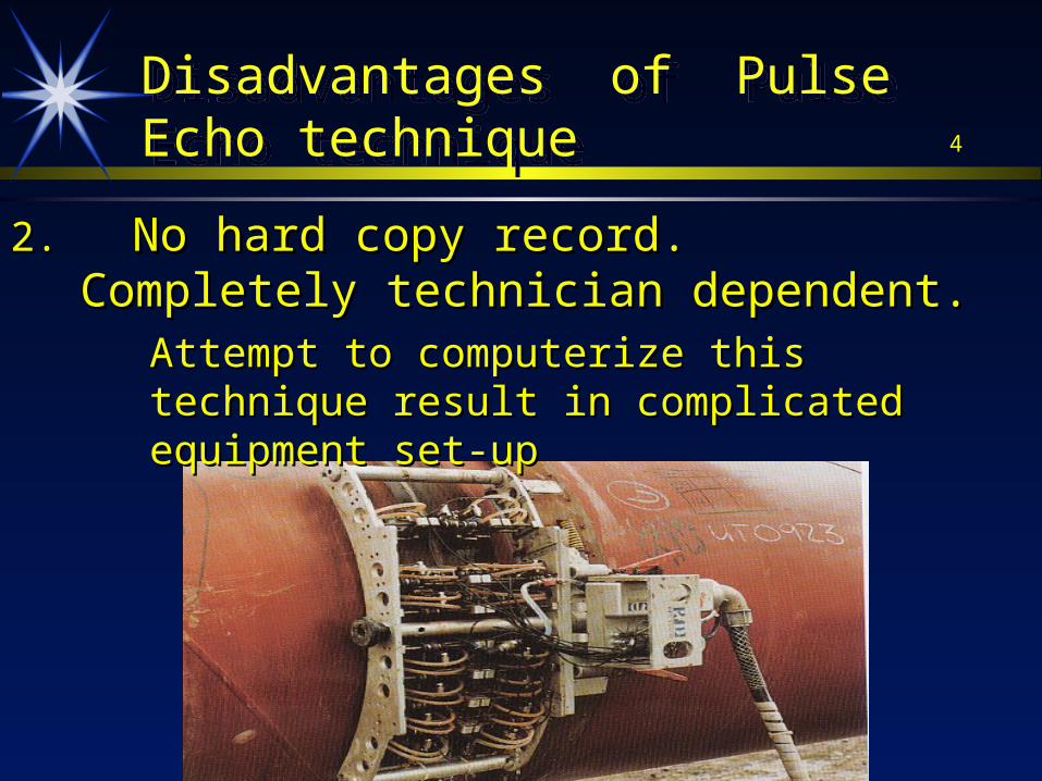
2. 2. No hard copy record. Completely technician No hard copy record. Completely technician dependent.dependent.
Attempt to computerize this technique result Attempt to computerize this technique result in complicated equipment set-upin complicated equipment set-up
5Disadvantages of Pulse Echo techniqueDisadvantages of Pulse Echo technique
3. Time consuming to size defect accurately, use of DAC curve to estimate defect size
6Disadvantages of Pulse Echo techniqueDisadvantages of Pulse Echo technique
As such, Radiography, which produces a As such, Radiography, which produces a picture, is utilized; even though defect picture, is utilized; even though defect detectability is lower than UT.detectability is lower than UT.
Radiography or X’ray produces Radiography or X’ray produces Radiation Radiation Safety Problems Safety Problems
Radiograhpy is time consuming on thick Radiograhpy is time consuming on thick materials or large diameters .materials or large diameters .
7Ultrasonic TOFDUltrasonic TOFD
Late 1970s , AEA ( Atomic Energy Authority) Late 1970s , AEA ( Atomic Energy Authority) of United Kingdom explored new ultrasonic of United Kingdom explored new ultrasonic technique technique
This technique utilizes sound This technique utilizes sound diffractiondiffraction from from defect tips, not defect tips, not reflectionreflection echoesechoes..
8
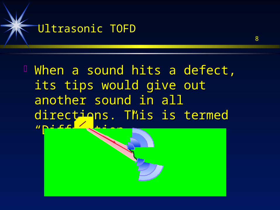
When a sound hits a defect, its tips would When a sound hits a defect, its tips would give out another sound in all directions. give out another sound in all directions. This is termed “Diffraction”This is termed “Diffraction”
Ultrasonic TOFD
9
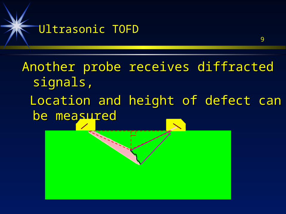
Another probe receives diffracted signals,Another probe receives diffracted signals,
Location and height of defect can be measuredLocation and height of defect can be measured
Ultrasonic TOFD
10Ultrasonic TOFDUltrasonic TOFD
Lateral Wave
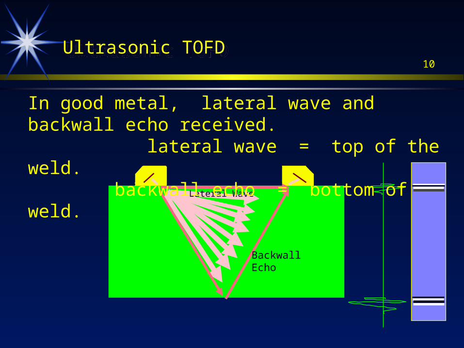
In good metal, lateral wave and backwall echo received. lateral wave = top of the weld. backwall echo = bottom of weld.
BackwallEcho
11Ultrasonic TOFDUltrasonic TOFD
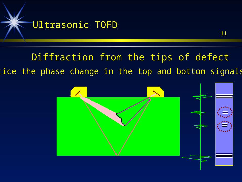
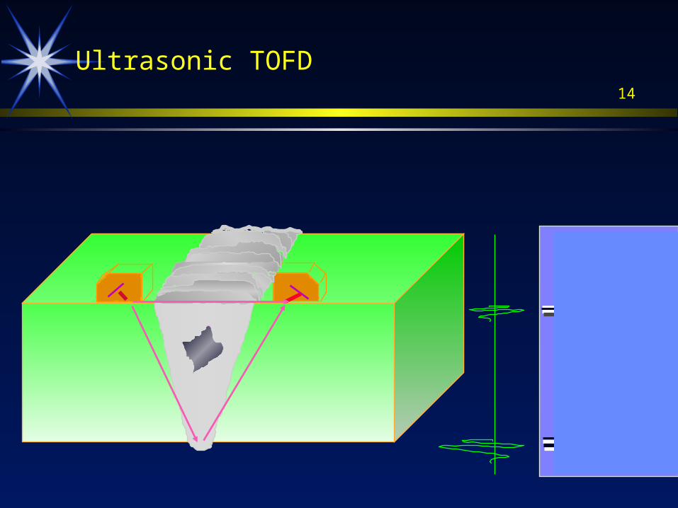
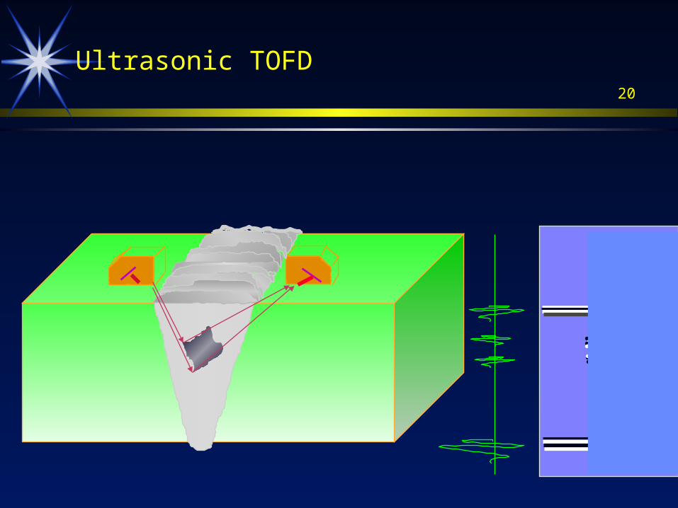
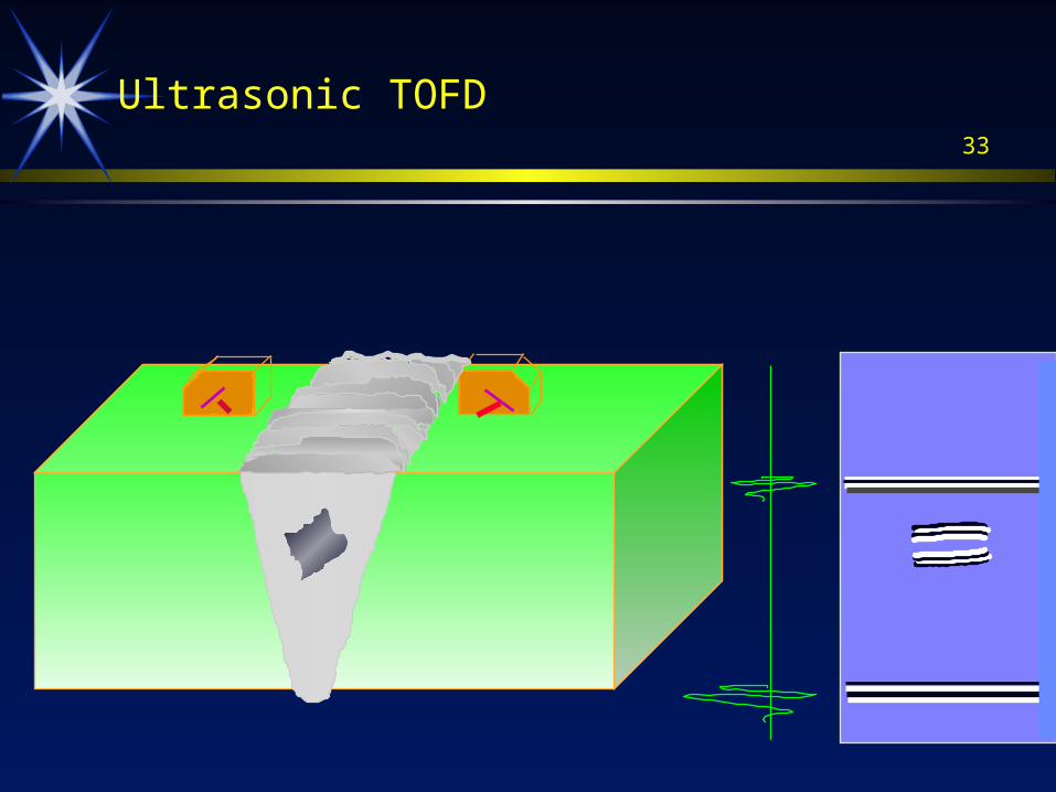
Diffraction from the tips of defect
Notice the phase change in the top and bottom signals
12
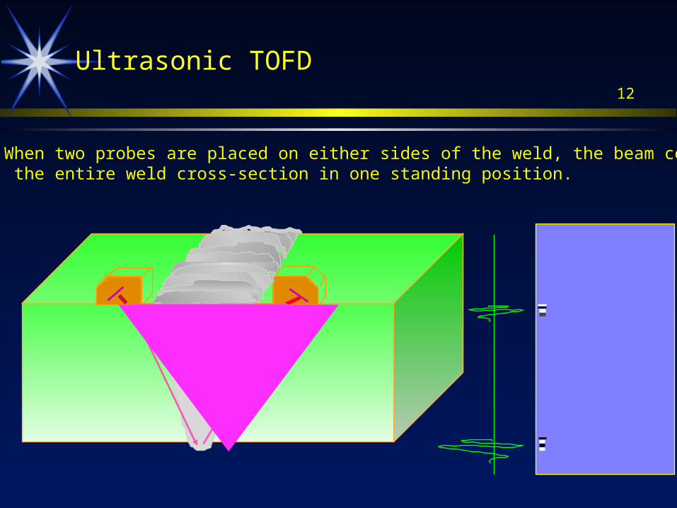
When two probes are placed on either sides of the weld, the beam covers the entire weld cross-section in one standing position.
Ultrasonic TOFD

13
When two probes are placed on either sides of the weld, the beam covers the entire weld cross-section in one standing position.
Ultrasonic TOFD
14
Ultrasonic TOFD

15
Ultrasonic TOFD

16
Ultrasonic TOFD

17
Ultrasonic TOFD

18
Ultrasonic TOFD

19
Ultrasonic TOFD
20
Ultrasonic TOFD

21
Ultrasonic TOFD

22
Ultrasonic TOFD

23
Ultrasonic TOFD

24
Ultrasonic TOFD

25
Ultrasonic TOFD

26
Ultrasonic TOFD

27
Ultrasonic TOFD

28
Ultrasonic TOFD

29
Ultrasonic TOFD

30
Ultrasonic TOFD

31
Ultrasonic TOFD

32
Ultrasonic TOFD
33
Ultrasonic TOFD

34
Ultrasonic TOFD
35
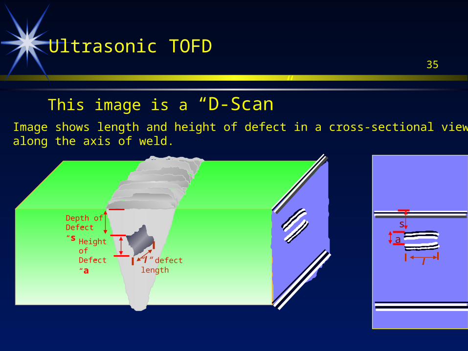
Image shows length and height of defect in a cross-sectional viewalong the axis of weld.
This image is a “D-Scan”
Ultrasonic TOFD
Depth of Defect “s”
Height of Defect “a”
a
s
“l “ defect length l

36
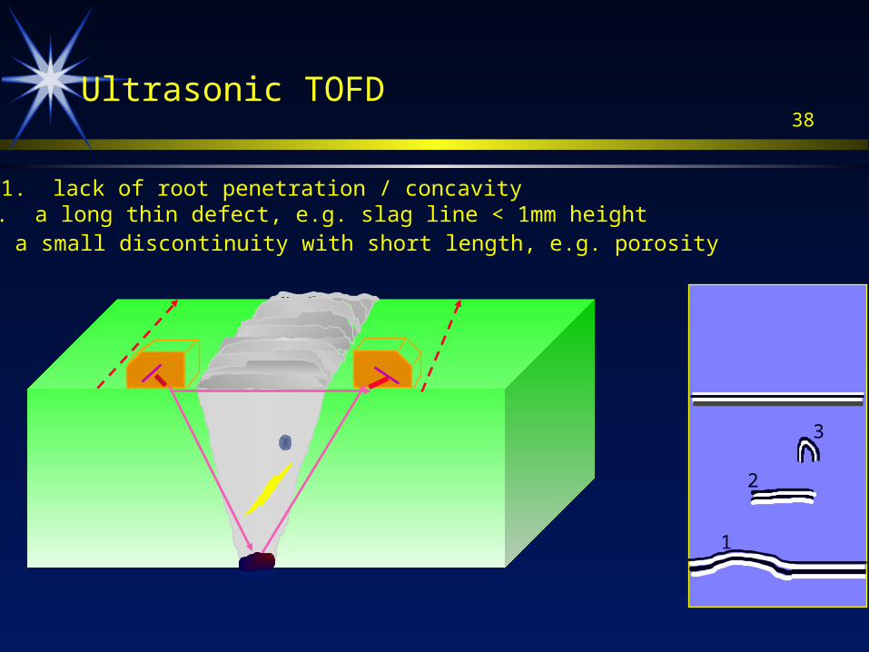
1. lack of root penetration / concavity
1
Ultrasonic TOFD

37
1. lack of root penetration / concavity
1
Ultrasonic TOFD
2
2. a long thin defect, e.g. slag line < 1mm height
38
1. lack of root penetration / concavity
1
Ultrasonic TOFD
2
2. a long thin defect, e.g. slag line < 1mm height
3
3. a small discontinuity with short length, e.g. porosity

39
40
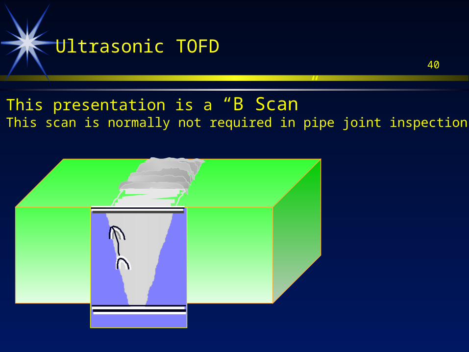
This presentation is a “B Scan”This scan is normally not required in pipe joint inspection
Ultrasonic TOFD
41
X’Ray GammaRay
TOFD UT P/E
20
40
60
80
100
0
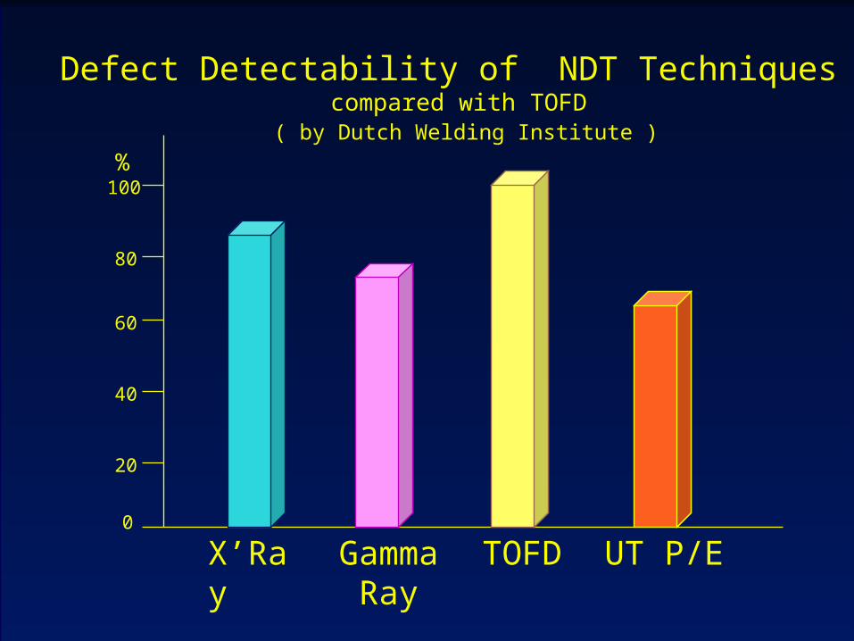
Defect Detectability of NDT Techniques compared with TOFD
( by Dutch Welding Institute )
%
42TOFD ApplicationTOFD Application
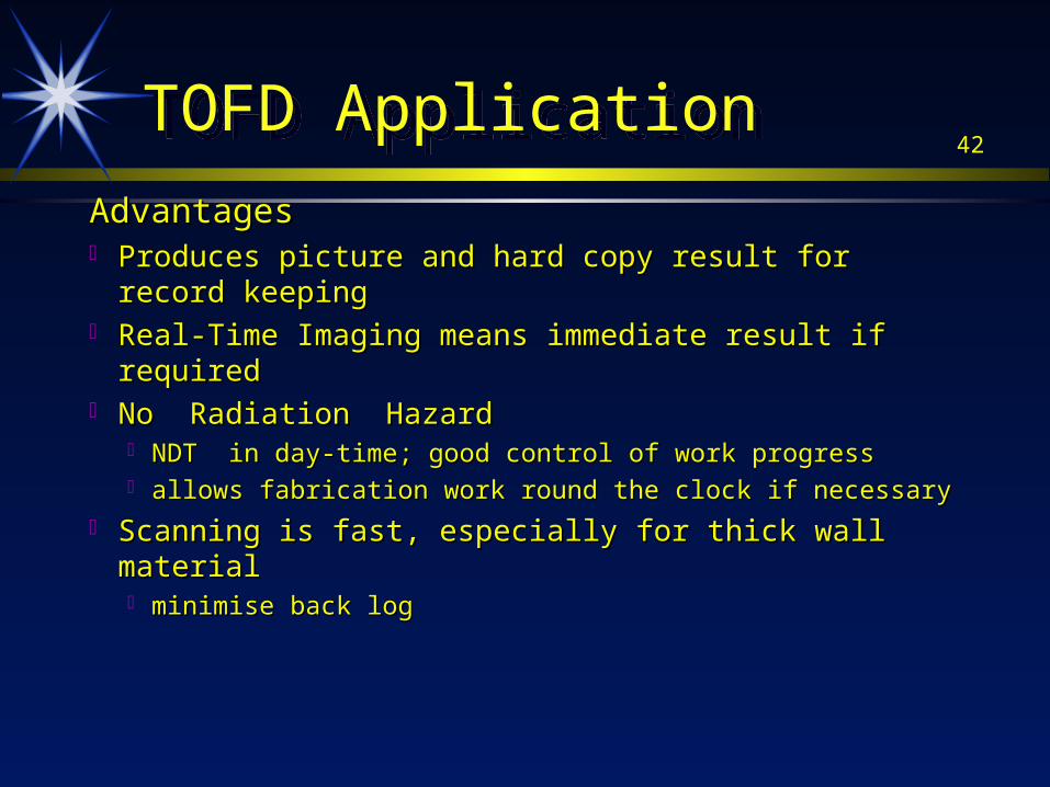
AdvantagesAdvantages Produces picture and hard copy result for record Produces picture and hard copy result for record
keepingkeeping Real-Time Imaging means immediate result if requiredReal-Time Imaging means immediate result if required No Radiation HazardNo Radiation Hazard
NDT in day-time; good control of work progressNDT in day-time; good control of work progress allows fabrication work round the clock if necessaryallows fabrication work round the clock if necessary
Scanning is fast, especially for thick wall materialScanning is fast, especially for thick wall material minimise back logminimise back log
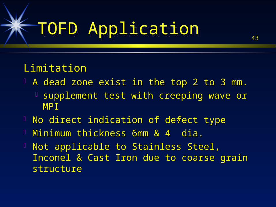
43TOFD ApplicationTOFD Application
LimitationLimitation A dead zone exist in the top 2 to 3 mm.A dead zone exist in the top 2 to 3 mm.
supplement test with creeping wave or MPIsupplement test with creeping wave or MPI No direct indication of defect typeNo direct indication of defect type Minimum thickness 6mm & 4” dia.Minimum thickness 6mm & 4” dia. Not applicable to Stainless Steel, Inconel & Cast Not applicable to Stainless Steel, Inconel & Cast
Iron due to coarse grain structureIron due to coarse grain structure
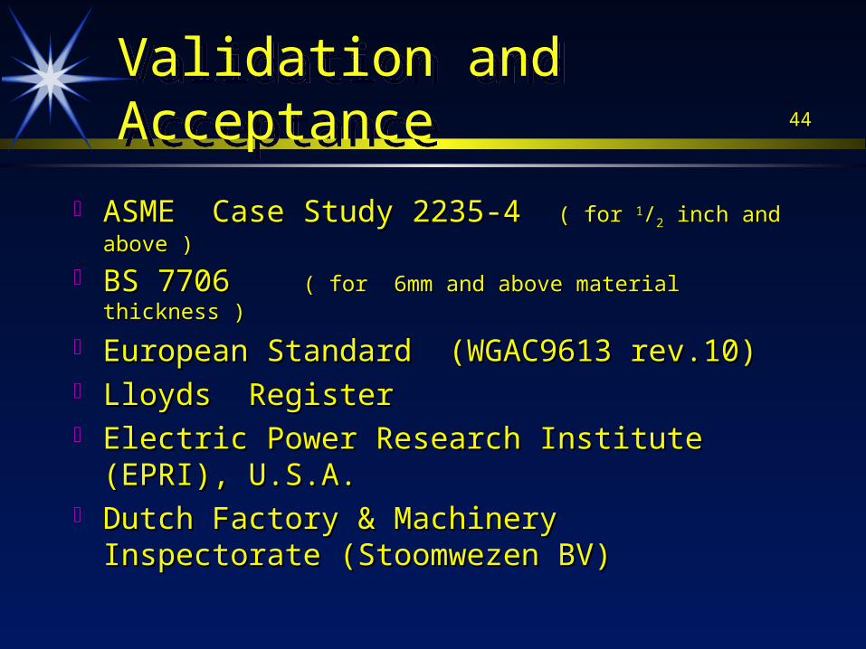
44Validation and AcceptanceValidation and Acceptance
ASME Case Study 2235-4 ASME Case Study 2235-4 ( for ( for 11//22 inch and above ) inch and above )
BS 7706 BS 7706 ( for 6mm and above material thickness )( for 6mm and above material thickness )
European Standard (WGAC9613 rev.10)European Standard (WGAC9613 rev.10) Lloyds RegisterLloyds Register Electric Power Research Institute (EPRI), U.S.A.Electric Power Research Institute (EPRI), U.S.A. Dutch Factory & Machinery Inspectorate Dutch Factory & Machinery Inspectorate
(Stoomwezen BV)(Stoomwezen BV)
45Defect Rejection CriteriaDefect Rejection Criteria
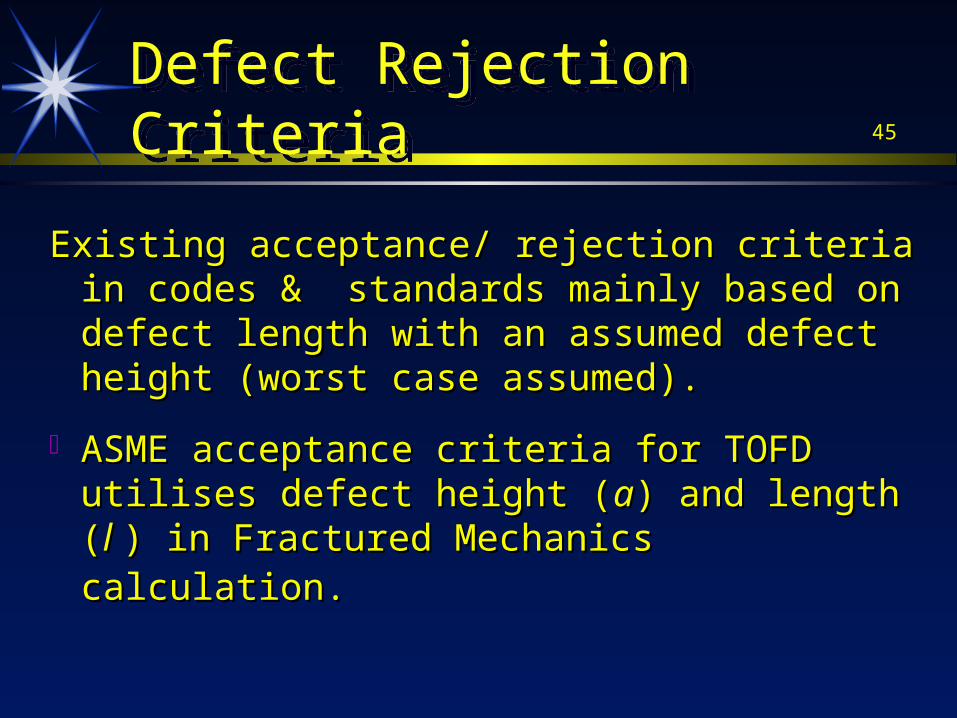
Existing acceptance/ rejection criteria in codes & Existing acceptance/ rejection criteria in codes & standards mainly based on defect length with an standards mainly based on defect length with an assumed defect height (worst case assumed).assumed defect height (worst case assumed).
ASME acceptance criteria for TOFD utilises ASME acceptance criteria for TOFD utilises defect height (defect height (aa) and length () and length (l l ) in Fractured ) in Fractured Mechanics calculation.Mechanics calculation.
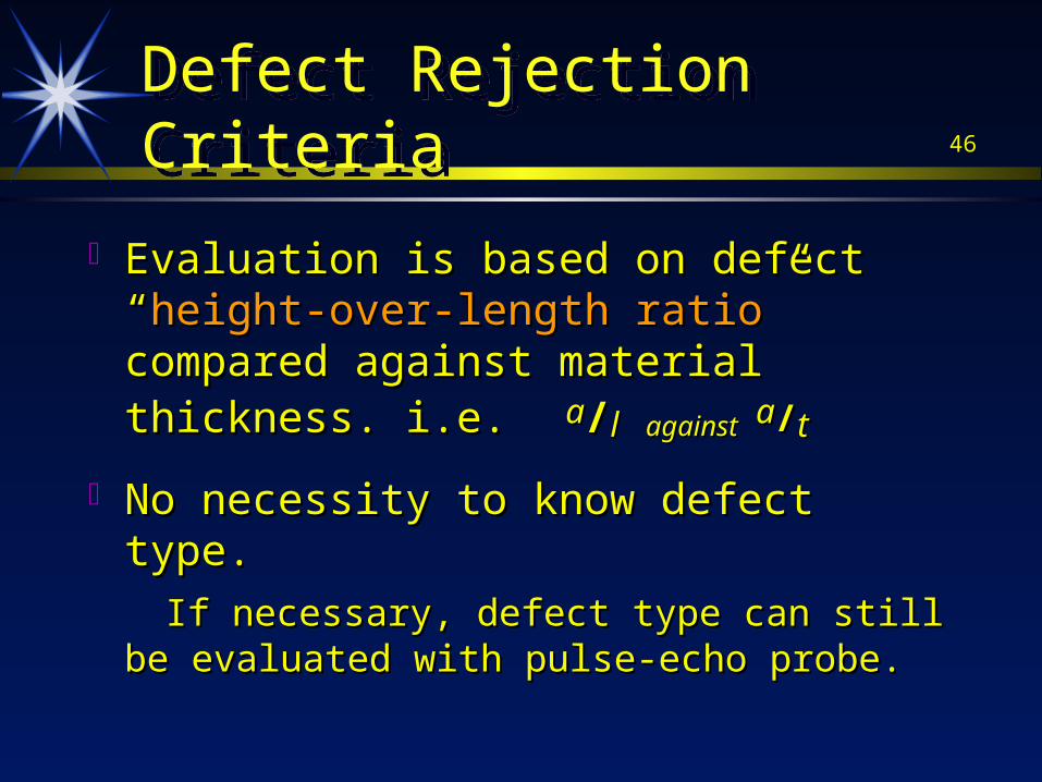
46Defect Rejection CriteriaDefect Rejection Criteria
Evaluation is based on defect “Evaluation is based on defect “height-over-height-over-length ratiolength ratio” compared against material ” compared against material thickness. i.e.thickness. i.e. aa//l l againstagainst aa//tt
No necessity to know defect type. No necessity to know defect type.
If necessary, defect type can still be evaluated with If necessary, defect type can still be evaluated with pulse-echo probe.pulse-echo probe.
47
Field Application Experience of MJ since 1996
Field Application Experience of MJ since 1996 Project Piping Construction --- in lieu of RTProject Piping Construction --- in lieu of RT
Shell LPG Plant Construction for Foster Wheeler/ Shell LPG Plant Construction for Foster Wheeler/ Kellogg/ JGCKellogg/ JGC
Shell MLNG Plant No.3 Construction for JGC/ Shell MLNG Plant No.3 Construction for JGC/ Kellogg Brown & Root and Slug Catcher for RanhillKellogg Brown & Root and Slug Catcher for Ranhill
Petronas Common Utilities Facilities construction Petronas Common Utilities Facilities construction for Foster Wheeler for Foster Wheeler
Gas Transmission Piping for JGC at Ourhoud, Gas Transmission Piping for JGC at Ourhoud, AlgeriaAlgeria
Ammonia Syn-Gas Plant construction for PetronasAmmonia Syn-Gas Plant construction for Petronas
48
Field ApplicationExperience of MJ since 1996
Field ApplicationExperience of MJ since 1996
Project Piping Construction --- in lieu of RTProject Piping Construction --- in lieu of RT Shell Sarawak Offshore M-1 Platform expansion Shell Sarawak Offshore M-1 Platform expansion
projectproject Exxon Pyrolysis Furnace Project for Agra Birwelco Exxon Pyrolysis Furnace Project for Agra Birwelco
LtdLtd Petronas RESAK Offshore Project for ProjassPetronas RESAK Offshore Project for Projass Petronas ANGSI Offshore Project for Sime-Petronas ANGSI Offshore Project for Sime-
SembawangSembawang Titan Chemicals TPP 2 Project for JGCTitan Chemicals TPP 2 Project for JGC
49
Field ApplicationExperience of MJ since 1996Field ApplicationExperience of MJ since 1996
Pressure Vessel fabrication --- in lieu of RT Pressure Vessel fabrication --- in lieu of RT Shell Refinery LPG Bullet Tank ConstructionShell Refinery LPG Bullet Tank Construction Insallah Project Algeria for JGC / MechmarInsallah Project Algeria for JGC / Mechmar Shell Sarawak B-11 Platform projectShell Sarawak B-11 Platform project Nippon Oil Helang Field Offshore projectNippon Oil Helang Field Offshore project Petronas/MTBE LPG Bullet Tank for Toyo/ KNMPetronas/MTBE LPG Bullet Tank for Toyo/ KNM Petronas Dagangan Bullet Tank for MechmarPetronas Dagangan Bullet Tank for Mechmar
50
Field ApplicationExperience of MJ since 1996Field ApplicationExperience of MJ since 1996
Monitoring Stress Corrosion Cracking in Monitoring Stress Corrosion Cracking in pipings & pressure vessels for refineries pipings & pressure vessels for refineries and chemical plants in Malaysia, Singapore.and chemical plants in Malaysia, Singapore.
Inspection of Spherical Tank & Reactors for Inspection of Spherical Tank & Reactors for service-induced defects for oil refineries in service-induced defects for oil refineries in Malaysia and Singapore & ThailandMalaysia and Singapore & Thailand
51
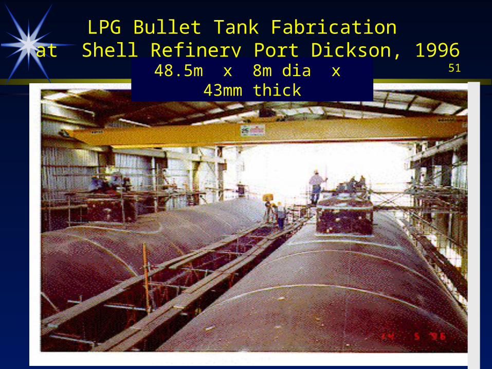
LPG Bullet Tank Fabrication at Shell Refinery Port Dickson, 1996
48.5m x 8m dia x 43mm thick
52
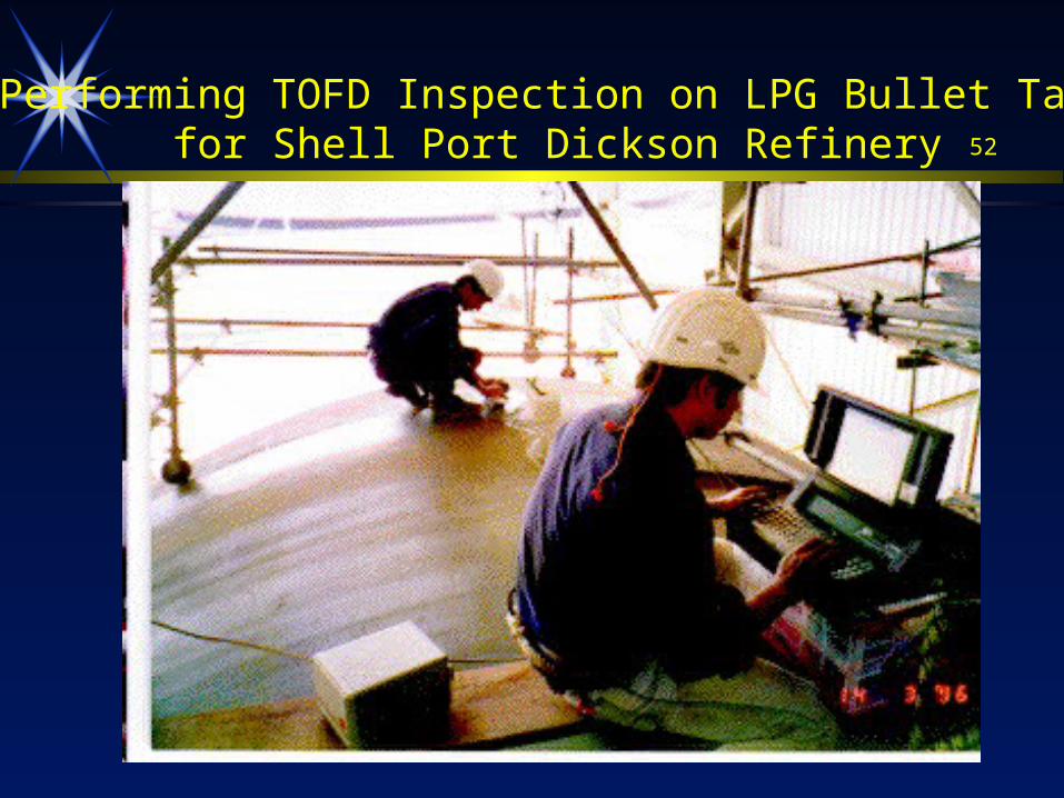
Performing TOFD Inspection on LPG Bullet Tankfor Shell Port Dickson Refinery
53
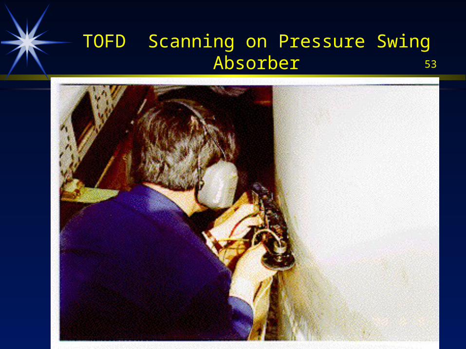
TOFD Scanning on Pressure Swing Absorber
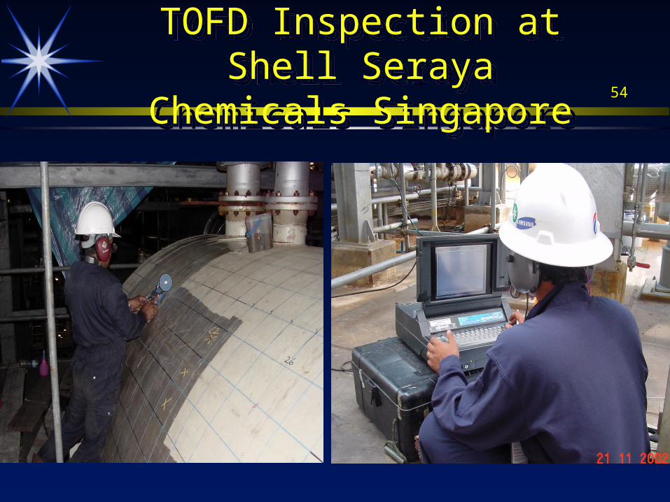
54
TOFD Inspection at Shell Seraya Chemicals SingaporeTOFD Inspection at Shell
Seraya Chemicals Singapore
55
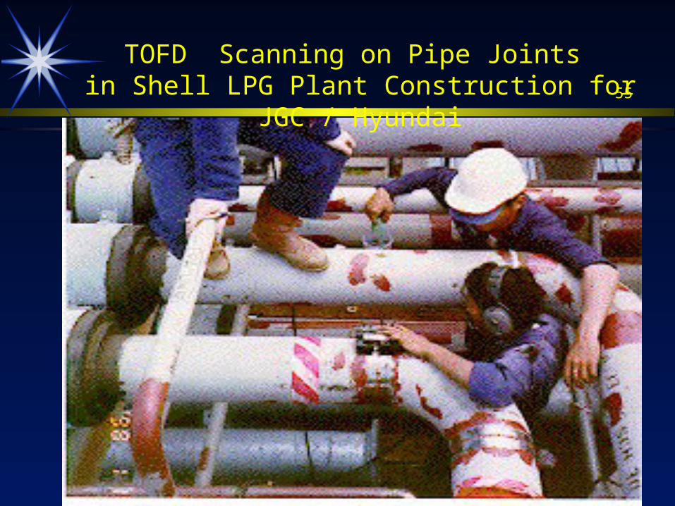
TOFD Scanning on Pipe Joints in Shell LPG Plant Construction for JGC / Hyundai
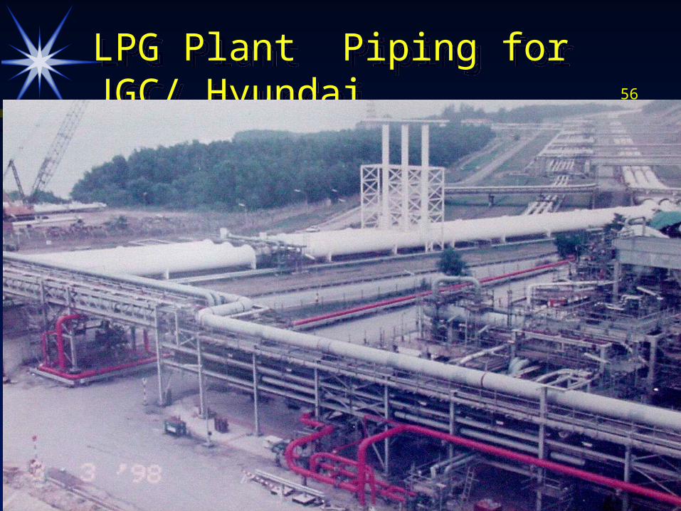
56LPG Plant Piping for JGC/ HyundaiLPG Plant Piping for JGC/ Hyundai
57
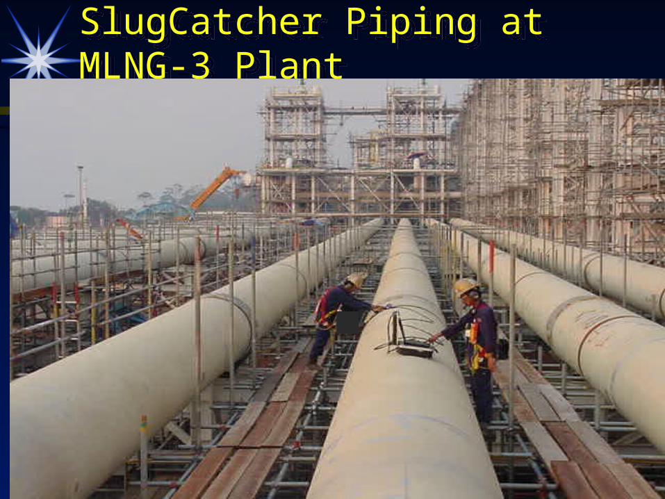
SlugCatcher Piping at MLNG-3 PlantSlugCatcher Piping at MLNG-3 Plant
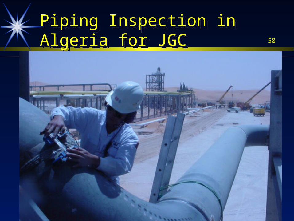
58Piping Inspection in Algeria for JGCPiping Inspection in Algeria for JGC
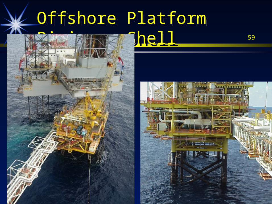
59Offshore Platform Piping --ShellOffshore Platform Piping --Shell
60
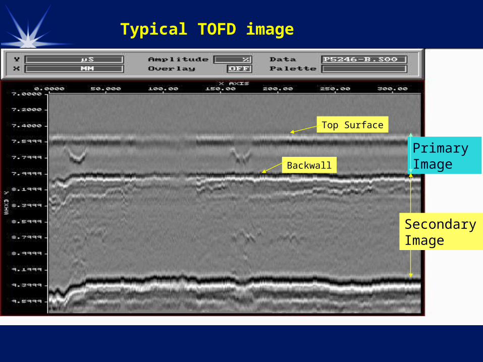
Top Surface
Backwall
Primary Image
Secondary Image
Typical TOFD image
61Porosi ty
Defec t Wi th L ength
Hi-low B ac k-wal l
La ck-Of-Root-Penet ra ti on
Ultrasonic TOFD Images
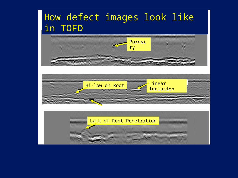
Porosity
Linear InclusionHi-low on Root
Lack of Root Penetration
How defect images look like in TOFD
Porosi ty
Defec t Wi th L ength
Hi-low B ac k-wal l
La ck-Of-Root-Penet ra ti on
Ultrasonic TOFD Images
Porosity
Linear InclusionHi-low on Root
Lack of Root Penetration
How defect images look like in TOFD
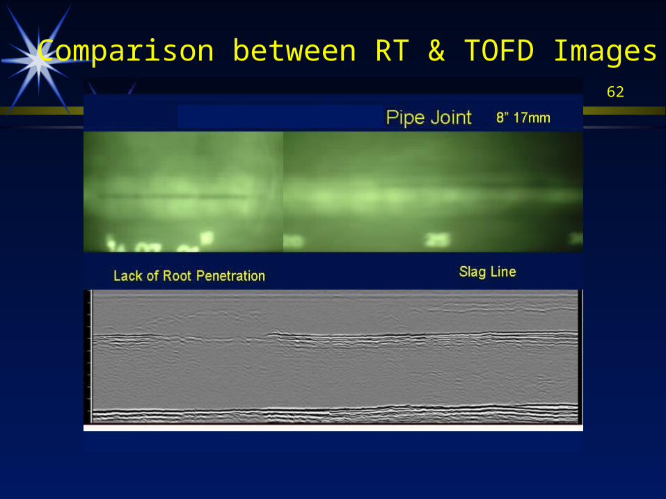
62
Comparison between RT & TOFD Images
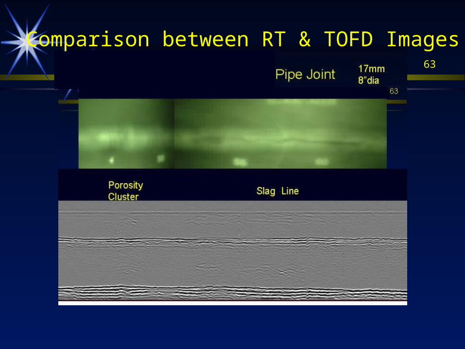
63
Comparison between RT & TOFD Images
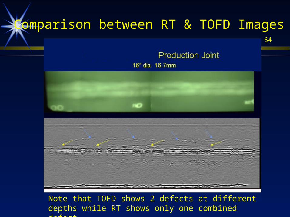
64
Comparison between RT & TOFD Images
Note that TOFD shows 2 defects at different depths while RT shows only one combined defect.
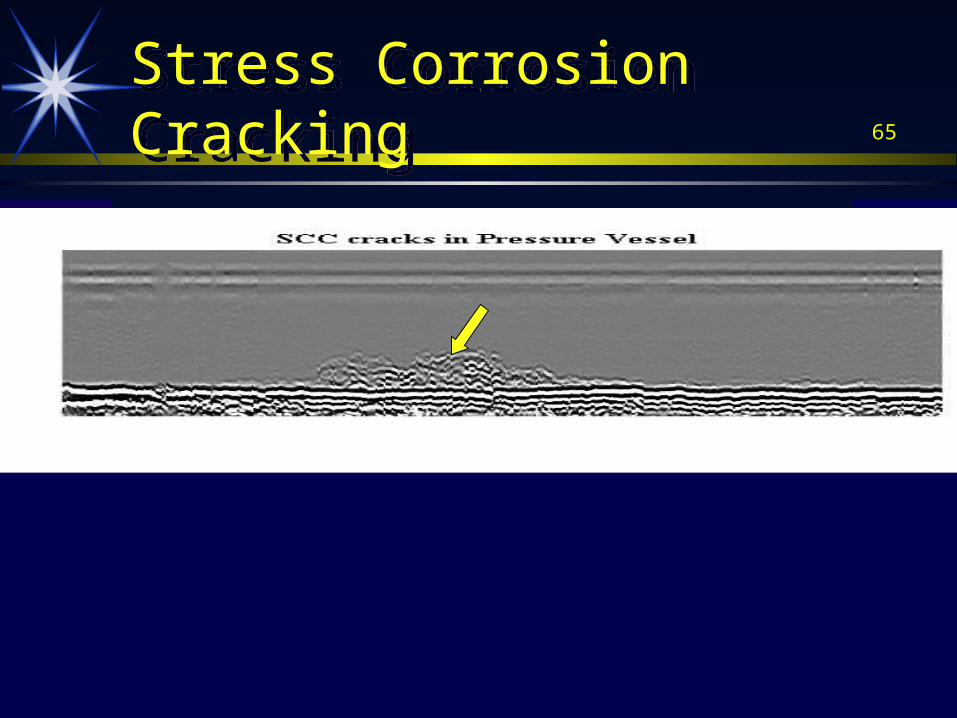
65Stress Corrosion CrackingStress Corrosion Cracking
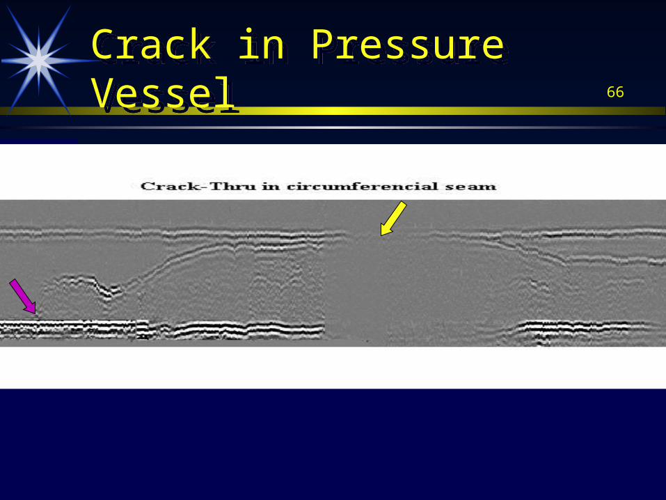
66Crack in Pressure VesselCrack in Pressure Vessel
67
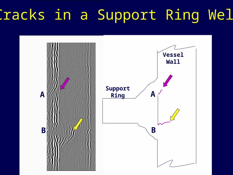
Cracks in a Support Ring Weld
A
B
A
B
SupportRing
VesselWall
68
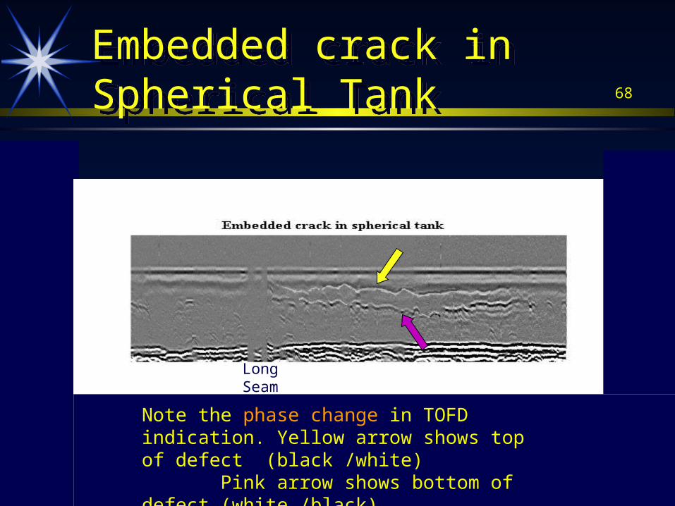
Embedded crack in Spherical TankEmbedded crack in Spherical Tank
LongSeam
LongSeam
Note the phase change in TOFD indication. Yellow arrow shows top of defect (black /white) Pink arrow shows bottom of defect (white /black)
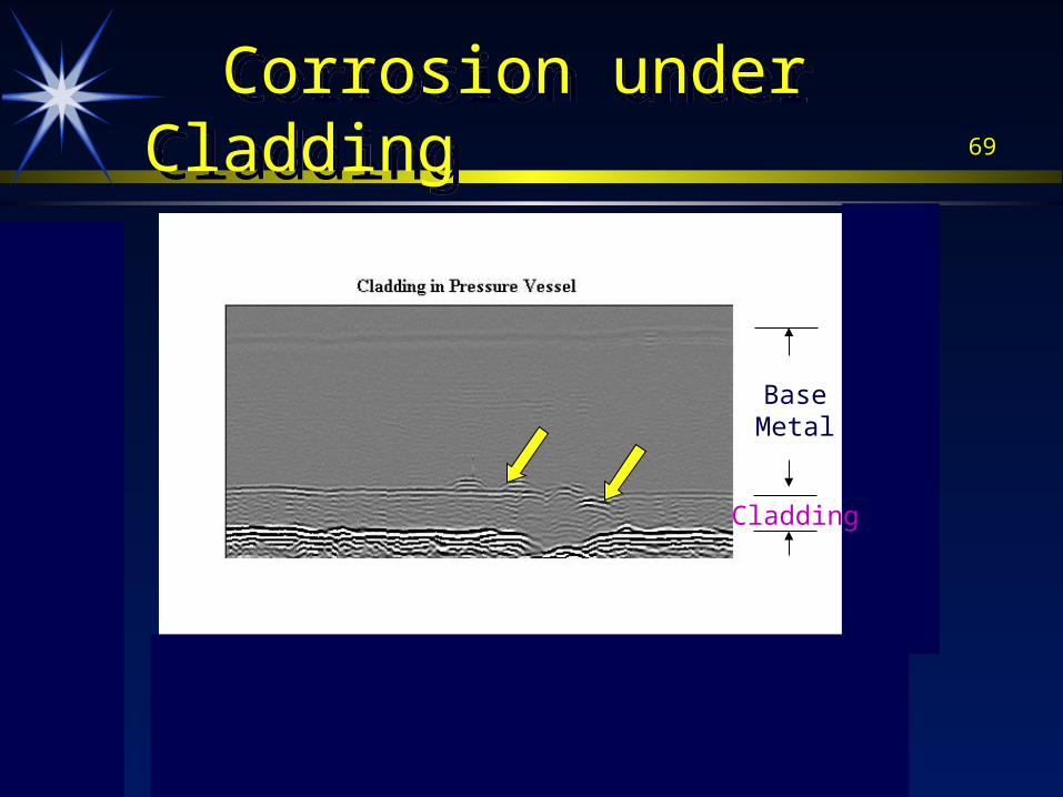
69 Corrosion under Cladding Corrosion under Cladding
BaseMetal
Cladding
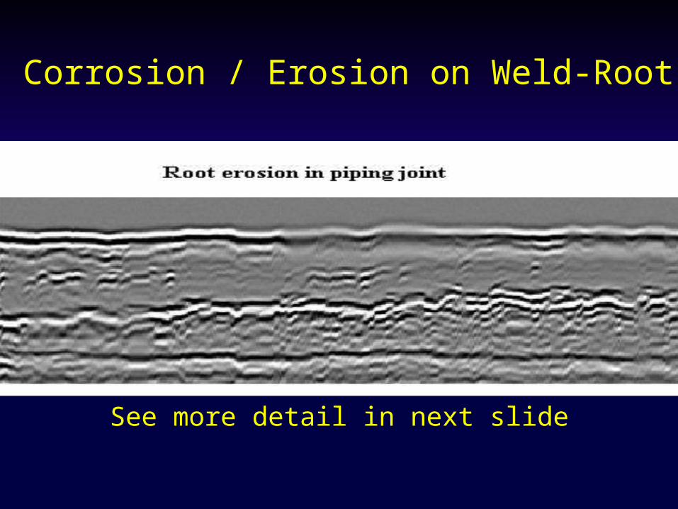
70Corrosion / Erosion on Weld-Root
See more detail in next slide
71
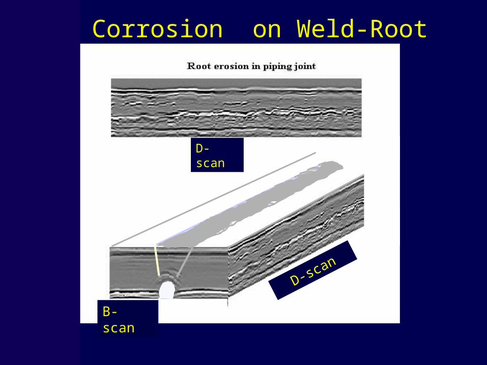
Corrosion on Weld-Root
B- scan
D-scan
D-scan
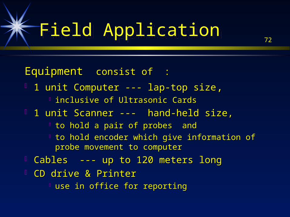
72Field Application Field Application
Equipment Equipment consist of :consist of : 1 unit Computer --- lap-top size1 unit Computer --- lap-top size, ,
inclusive of Ultrasonic Cardsinclusive of Ultrasonic Cards
1 unit Scanner --- hand-held size, 1 unit Scanner --- hand-held size, to hold a pair of probes and to hold a pair of probes and to hold encoder which give information of probe movement to to hold encoder which give information of probe movement to
computercomputer
Cables --- up to 120 meters longCables --- up to 120 meters long CD drive & Printer CD drive & Printer
use in office for reportinguse in office for reporting
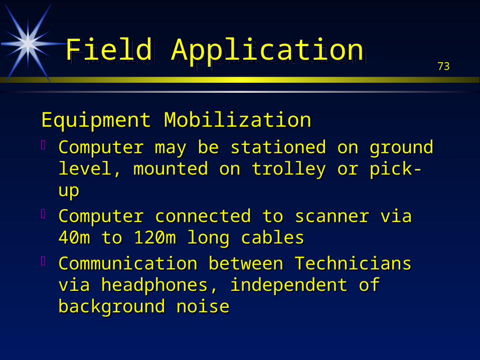
73Field ApplicationField Application
Equipment MobilizationEquipment Mobilization Computer may be stationed on ground level, Computer may be stationed on ground level,
mounted on trolley or pick-upmounted on trolley or pick-up Computer connected to scanner via 40m to 120m Computer connected to scanner via 40m to 120m
long cableslong cables Communication between Technicians via Communication between Technicians via
headphones, independent of background noiseheadphones, independent of background noise
74Field ApplicationField Application
ManpowerManpower
A team normally consists of 3 personnelA team normally consists of 3 personnel 1 number Level II Technician1 number Level II Technician 2 numbers Level I Technician2 numbers Level I Technician
Additional helper for cleaning weldAdditional helper for cleaning weld
75Field ApplicationField Application
Weld Preparation for TOFDWeld Preparation for TOFD Avoid grindingAvoid grinding base metal --base metal --
--favorite practice of welder to remove undercut and spatter by favorite practice of welder to remove undercut and spatter by grinding grinding
Grinding creates uneven surface and makes probe contact Grinding creates uneven surface and makes probe contact difficultdifficult
Use scrapper, chisel or sanding disc, to remove spatterUse scrapper, chisel or sanding disc, to remove spatter
Make weld cap as narrow as possible. Avoid Make weld cap as narrow as possible. Avoid excessive weld reinforcement. This also reduces excessive weld reinforcement. This also reduces amount of welding.amount of welding.
76
The EndThe End
Thank YouThank You
For further enquiry, please contact us at :For further enquiry, please contact us at :
Email : [email protected] : [email protected]


![Boeing Group Assignment for Improvement[Rev03]](https://img.pdfslide.us/doc/110x75/54f9f3c54a7959575b8b45b4/boeing-group-assignment-for-improvementrev03.jpg)