Embed Size (px)
Citation preview

7/23/2019 IAQPoint2 Manual ENG Rev03
http://slidepdf.com/reader/full/iaqpoint2-manual-eng-rev03 1/80
IAQPoint2TM Indoor Air Quality Monitor
Technical Manual

7/23/2019 IAQPoint2 Manual ENG Rev03
http://slidepdf.com/reader/full/iaqpoint2-manual-eng-rev03 2/80

7/23/2019 IAQPoint2 Manual ENG Rev03
http://slidepdf.com/reader/full/iaqpoint2-manual-eng-rev03 3/801
IAQPoint2™
Introduction ...................................................................................................................3
Air Quality ...................................................................................................................4
Danger/Warning/Caution/Notes ................................................................................ 5
Contact information ......................................................................................................6
Americas .................................................................................................................... 6
Europe, Middle East, and Africa................................................................................ 6
Asia Pacific .................................................................................................................6
Technical Services .....................................................................................................6
Glossary ..................................................................................................................... 7
Configurations ............................................................................................................... 8
Dimensions ..................................................................................................................11
Wiring and installation ................................................................................................. 11
Wall-mounting procedure .......................................................................................17
Duct-mounting procedure .......................................................................................20
Operation ..................................................................................................................... 24First power-up .......................................................................................................... 24
Commissioning ........................................................................................................ 24
Warm-up ...................................................................................................................25
The ABC algorithm ................................................................................................... 25
Output levels ............................................................................................................... 26
Configuration of Display Units ....................................................................................28
Calibration ...................................................................................................................44
CO2 Calibration ........................................................................................................ 44
VOC Calibration .......................................................................................................45
Temperature Calibration .......................................................................................... 45rH Calibration ........................................................................................................... 46
Troubleshooting ....................................................................................................... 47
Faults and warning messages ................................................................................ 47
Maintenance ................................................................................................................55
Sensor accuracy test ...............................................................................................55
Sensor poisons/inhibitors ........................................................................................55
Specifications .............................................................................................................. 56
Modbus ........................................................................................................................ 57
Modbus registers ....................................................................................................57
BACnet ........................................................................................................................ 59Introduction .............................................................................................................. 59
BACnet Protocol Implementation Conformance Statement .................................. 59
BACNet Objects and Properties .............................................................................64
Limited Warranty ......................................................................................................... 73
Index ............................................................................................................................ 75
Table of Contents

7/23/2019 IAQPoint2 Manual ENG Rev03
http://slidepdf.com/reader/full/iaqpoint2-manual-eng-rev03 4/802
IAQPoint2™
7/23/2019 IAQPoint2 Manual ENG Rev03
http://slidepdf.com/reader/full/iaqpoint2-manual-eng-rev03 5/803
IAQPoint2™
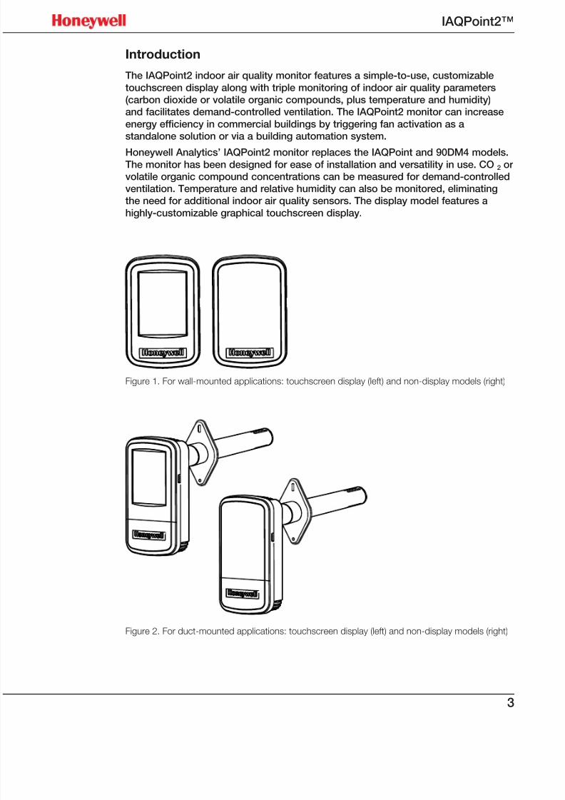
Introduction
The IAQPoint2 indoor air quality monitor features a simple-to-use, customizable
touchscreen display along with triple monitoring of indoor air quality parameters(carbon dioxide or volatile organic compounds, plus temperature and humidity)and facilitates demand-controlled ventilation. The IAQPoint2 monitor can increase
energy efficiency in commercial buildings by triggering fan activation as a
standalone solution or via a building automation system.Honeywell Analytics’ IAQPoint2 monitor replaces the IAQPoint and 90DM4 models.
The monitor has been designed for ease of installation and versatility in use. CO2 orvolatile organic compound concentrations can be measured for demand-controlledventilation. Temperature and relative humidity can also be monitored, eliminatingthe need for additional indoor air quality sensors. The display model features a
highly-customizable graphical touchscreen display.
Figure 1. For wall-mounted applications: touchscreen display (left) and non-display models (right)
Figure 2. For duct-mounted applications: touchscreen display (left) and non-display models (right)
7/23/2019 IAQPoint2 Manual ENG Rev03
http://slidepdf.com/reader/full/iaqpoint2-manual-eng-rev03 6/804
IAQPoint2™
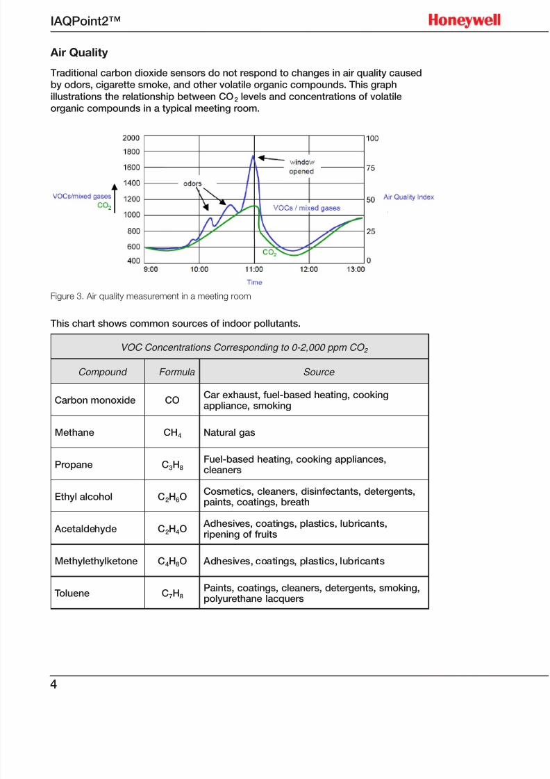
Air Quality
Traditional carbon dioxide sensors do not respond to changes in air quality causedby odors, cigarette smoke, and other volatile organic compounds. This graph
illustrations the relationship between CO2 levels and concentrations of volatileorganic compounds in a typical meeting room.
Figure 3. Air quality measurement in a meeting room
This chart shows common sources of indoor pollutants.
VOC Concentrations Corresponding to 0-2,000 ppm CO 2
Compound Formula Source
Carbon monoxide COCar exhaust, fuel-based heating, cooking
appliance, smoking
Methane CH4 Natural gas
Propane C3H8Fuel-based heating, cooking appliances,cleaners
Ethyl alcohol C2H6OCosmetics, cleaners, disinfectants, detergents,paints, coatings, breath
Acetaldehyde C2H4O Adhesives, coatings, plastics, lubricants,ripening of fruits
Methylethylketone C4H8O Adhesives, coatings, plastics, lubricants
Toluene C7H8Paints, coatings, cleaners, detergents, smoking,polyurethane lacquers
7/23/2019 IAQPoint2 Manual ENG Rev03
http://slidepdf.com/reader/full/iaqpoint2-manual-eng-rev03 7/805
IAQPoint2™
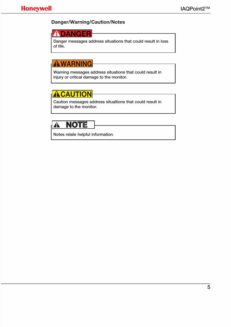
Danger/Warning/Caution/Notes
Danger messages address situations that could result in lossof life.
DANGER!
Warning messages address situations that could result ininjury or critical damage to the monitor.
WARNING!
Caution messages address situaltions that could result indamage to the monitor.
CAUTION!
Notes relate helpful information.
NOTE!

7/23/2019 IAQPoint2 Manual ENG Rev03
http://slidepdf.com/reader/full/iaqpoint2-manual-eng-rev03 8/806
IAQPoint2™
Contact information
www.honeywell.com
www.honeywellanalytics.com
Americas
Honeywell Analytics4005 Matte Blvd., Local G
Brossard, Québec, Canada J4Y 2P4
Tel: 1 450 619 1450
Toll free: 1 800 563 2967
Fax: 1 888 967 9938
Honeywell Analytics
405 Barclay Boulevard
Lincolnshire, Illinois, USA 60069
Tel: +1 847 955 8200Toll free: +1 800 538 0363
Fax: +1 847 955 8208
Europe, Middle East, and Africa
Life Safety Distribution AG
Wilstrasse 11-U11
CH-8610 Uster
Switzerland
Tel: +41 (0)1 943 4300Fax: +41 (0)1 943 4398
Asia Pacific
Honeywell Analytics Asia Pacific
#508, Kolon Science Valley (1)
187-10 Guro-Dong, Guro-Gu
Seoul, 152-729
Korea
Tel: +82 (0)2 6909 0307
Fax: +82 (0)2 2025 0328
Technical Services
7/23/2019 IAQPoint2 Manual ENG Rev03
http://slidepdf.com/reader/full/iaqpoint2-manual-eng-rev03 9/807
IAQPoint2™
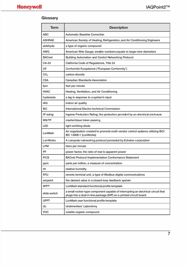
Glossary
Term Description
ABC Automatic Baseline Correction
ASHRAE American Society of Heating, Refrigeration, and Air Conditioning Engineers
aldehyde a type of organic compound
AWG American Wire Gauge; smaller numbers equate to larger wire diameters
BACnet Building Automation and Control Networking Protocol
CA-24 California Code of Regulations, Title 24
CE Conformité Européenne (“European Conformity”)
CO2 carbon dioxide
CSA Canadian Standards Association
fpm feet per minute
HVAC Heating, Ventilation, and Air Conditioning
hysteresis a lag in response to a system’s input
IAQ indoor air quality
IEC International Electro-technical Commission
IP rating Ingress Protection Rating; the protection provided by an electrical enclosure
MS/TP master/slave token passing
LED light-emitting diode
LonMark An organization created to promote multi-vendor control systems utilizing ISO/
IEC 14908-1 (LonWorks)
LonWorks A computer networking protocol promoted by Echelon corporation
LPM liters per minute
PF power factor, the ratio of real to apparent power
PICS BACnet Protocol Implementation Conformance Statement
ppm parts per million, a measure of concentration
rH relative humidity
RTU remote terminal unit, a type of Modbus digital communications
setpoint the desired value in a closed-loop feedback system
SFPT LonMark standard functional prole template
slide switcha small rocker-type component capable of interrupting an electrical circuit that
plugs into a dual in-line package (DIP) on a printed circuit board.
UFPT LonMark user functional prole template
UL Underwriters’ Laboratory
VOC volatile organic compound
7/23/2019 IAQPoint2 Manual ENG Rev03
http://slidepdf.com/reader/full/iaqpoint2-manual-eng-rev03 10/808
IAQPoint2™
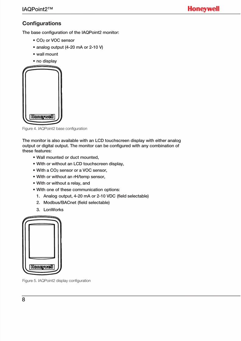
Congurations
The base configuration of the IAQPoint2 monitor:
• CO2 or VOC sensor
• analog output (4-20 mA or 2-10 V)
• wall mount
• no display
Figure 4. IAQPoint2 base confguration
The monitor is also available with an LCD touchscreen display with either analog
output or digital output. The monitor can be configured with any combination ofthese features:
• Wall mounted or duct mounted,
• With or without an LCD touchscreen display,
• With a CO2 sensor or a VOC sensor,
• With or without an rH/temp sensor,
• With or without a relay, and
• With one of these communication options:
1. Analog output, 4-20 mA or 2-10 VDC (field selectable)
2. Modbus/BACnet (field selectable)
3. LonWorks
Figure 5. IAQPoint2 display confguration
7/23/2019 IAQPoint2 Manual ENG Rev03
http://slidepdf.com/reader/full/iaqpoint2-manual-eng-rev03 11/809
IAQPoint2™
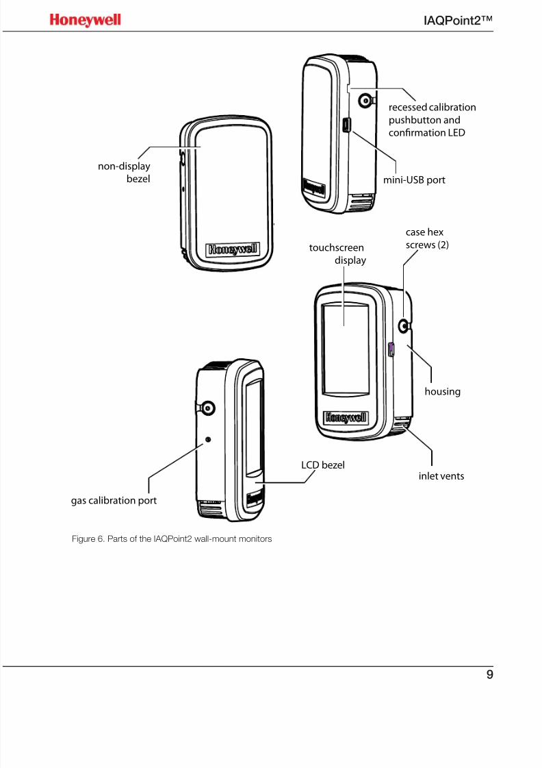
recessed calibration
pushbutton and
confirmation LED
non-display
bezel
housing
inlet vents
gas calibration port
touchscreen
display
case hex
screws (2)
mini-USB port
LCD bezel
Figure 6. Parts of the IAQPoint2 wall-mount monitors
7/23/2019 IAQPoint2 Manual ENG Rev03
http://slidepdf.com/reader/full/iaqpoint2-manual-eng-rev03 12/8010
IAQPoint2™
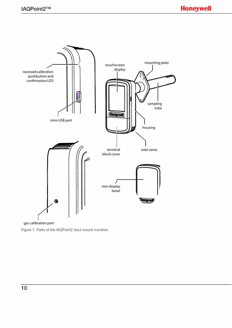
Figure 7. Parts of the IAQPoint2 duct-mount monitors
gas calibration port
recessed calibration
pushbutton and
confirmation LED
case hex
screws (2)
mini-USB port
touchscreen
display
sampling
tube
housing
inlet ventsterminal
block cover
mounting plate
non-display
bezel
7/23/2019 IAQPoint2 Manual ENG Rev03
http://slidepdf.com/reader/full/iaqpoint2-manual-eng-rev03 13/8011
IAQPoint2™
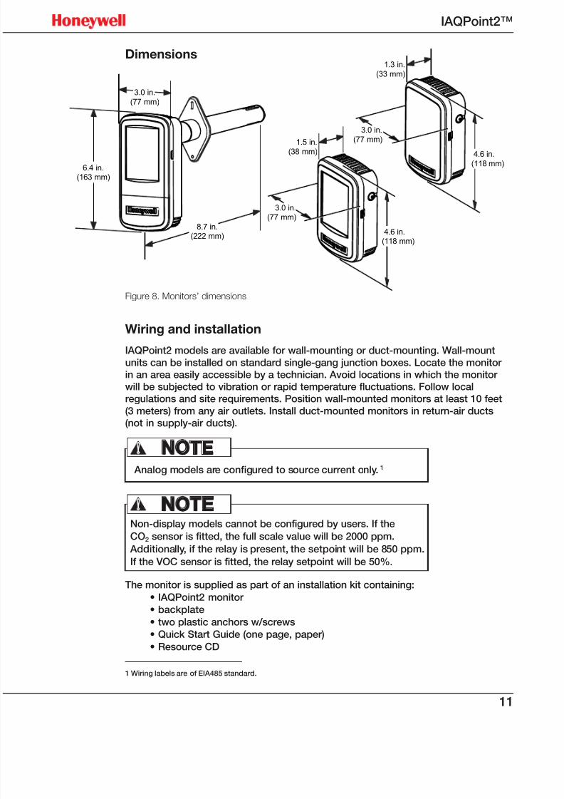
Dimensions
Figure 8. Monitors’ dimensions
Wiring and installation
IAQPoint2 models are available for wall-mounting or duct-mounting. Wall-mount
units can be installed on standard single-gang junction boxes. Locate the monitorin an area easily accessible by a technician. Avoid locations in which the monitorwill be subjected to vibration or rapid temperature fluctuations. Follow localregulations and site requirements. Position wall-mounted monitors at least 10 feet
(3 meters) from any air outlets. Install duct-mounted monitors in return-air ducts
(not in supply-air ducts).
Analog models are configured to source current only.1
NOTE!
Non-display models cannot be configured by users. If the
CO2 sensor is fitted, the full scale value will be 2000 ppm.
Additionally, if the relay is present, the setpoint will be 850 ppm.
If the VOC sensor is fitted, the relay setpoint will be 50%.
NOTE!
The monitor is supplied as part of an installation kit containing:
• IAQPoint2 monitor
• backplate
• two plastic anchors w/screws
• Quick Start Guide (one page, paper)
• Resource CD
1 Wiring labels are of EIA485 standard.
8.7 in.
(222 mm)
3.0 in.
(77 mm)
6.4 in.
(163 mm)
1.3 in.
(33 mm)
3.0 in.
(77 mm)
4.6 in.
(118 mm)
1.5 in.(38 mm)
3.0 in.
(77 mm)
4.6 in.
(118 mm)
7/23/2019 IAQPoint2 Manual ENG Rev03
http://slidepdf.com/reader/full/iaqpoint2-manual-eng-rev03 14/8012
IAQPoint2™
An optional calibration kit is also available. The kit contains:
• test gas
• M-502875: 0.5LPM Regulator for 58 & 103L Cylinders
• M-502585: 0.5LPM Regulator for 17L Cylinders
• M-501038: CAL GAS 17L CYLINDER NITROGEN (N2)
• M-501011: CAL GAS 103L CYLINDER NITROGEN (N2)
• M-501010: CAL GAS 103L CYLINDER 1,000 PPM CO2 BAL N2
• M-500989: CAL GAS 103L CYLINDER 2,000 PPM CO2 BAL N2• M-512438: CALIBRATION ADAPTER IAQPOINT
• M-508808: CAL KIT TUBING 6 FEET 1/8 I.D. X 1/4 O.D.
Tools needed:
• drill
• drill bit
• #2 Phillips and 1/8 inch (3 mm) straight screwdrivers
• wire strippers
The IAQPoint2 Air Quality Monitor is not designed for industrialapplications or for use in hazardous locations.
CAUTION!
Digital models of the IAQPoint2 monitor should be wired as indicated on the label.Note that the meaning of the A and B symbols for EIA/RS-485 wiring varies amongvendors. Terminal 6 corresponds to BACnet ‘+’, the Modbus ‘D1’ and the EIA/RS-485‘B’. Terminal 5 corresponds to BACnet ‘-‘, the Modbus ‘D0’, and EIA/RS-485 ‘A’.
Line voltages may be present on the relay terminals.
DANGER!
7/23/2019 IAQPoint2 Manual ENG Rev03
http://slidepdf.com/reader/full/iaqpoint2-manual-eng-rev03 15/8013
IAQPoint2™
IAQPoint2 Duct Mount Analog
Note:
RLoad = 0 – 500Ω in mA mode
1
2
3NO
NC
Com
load
loadEnergized when IAQ good
Energized when IAQ poor
250 VAC, 30 VDC max
7
8
9
10
24 VAC/DCInternal
loads
4
5
6
+
-
14.5VDC
5 0 0 Ω
5 0 0 Ω
5 0 0 Ω
4 - 2 0 m A g a s s i g n a l
4 - 2 0 m A g a s o r t e m p s i g n a l
4 - 2 0 m A r H s i g n a l
R L o a d
R L o a d
R L o a d
External Controller
Ch. 3
Ch. 2
Ch. 1
Common-
+
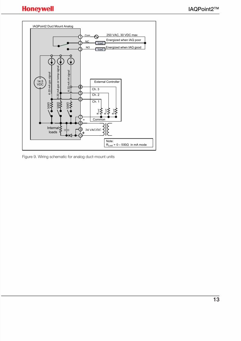
Figure 9. Wiring schematic for analog duct-mount units
7/23/2019 IAQPoint2 Manual ENG Rev03
http://slidepdf.com/reader/full/iaqpoint2-manual-eng-rev03 16/8014
IAQPoint2™
IAQPoint2 Wall Mount Analog
1
2
3
NO
NC
Com
load
load
Energized when IAQ good
Energized when IAQ poor
250 VAC, 30 VDC max
Note:
RLoad = 0 – 500Ω in mA mode
7
8
9
10
24 VAC/DCInternal
loads
4
5
6
+
-
14.5VDC
5 0 0 Ω
5 0 0 Ω
5 0 0 Ω
4 - 2 0 m A g a s s i g n a l
4 - 2 0 m A g a s o r t e m p s i g n a l
4 - 2 0 m A r H s i g n a l
R L o a d
R L o a d
R L o a d
External Controller
Ch. 3
Ch. 2
Ch. 1
Common-
+
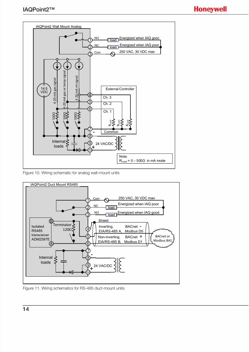
Figure 10. Wiring schematic for analog wall-mount units
IAQPoint2 Duct Mount RS485
1
2
3NO
NC
Com
load
loadEnergized when IAQ good
Energized when IAQ poor
250 VAC, 30 VDC max
7
8
9
10
24 VAC/DC
Internal
loads
4
5
6 A
B
Isolated
RS485
transceiver
ADM2587E
Terminator
120ΩInverting, BACnet -EIA/RS-485 A, Modbus D0
BACnet or
Modbus BAS
Non-inverting, BACnet +EIA/RS-485 B, Modbus D1
Shield
+
-
Figure 11. Wiring schematics for RS-485 duct-mount units
7/23/2019 IAQPoint2 Manual ENG Rev03
http://slidepdf.com/reader/full/iaqpoint2-manual-eng-rev03 17/8015
IAQPoint2™
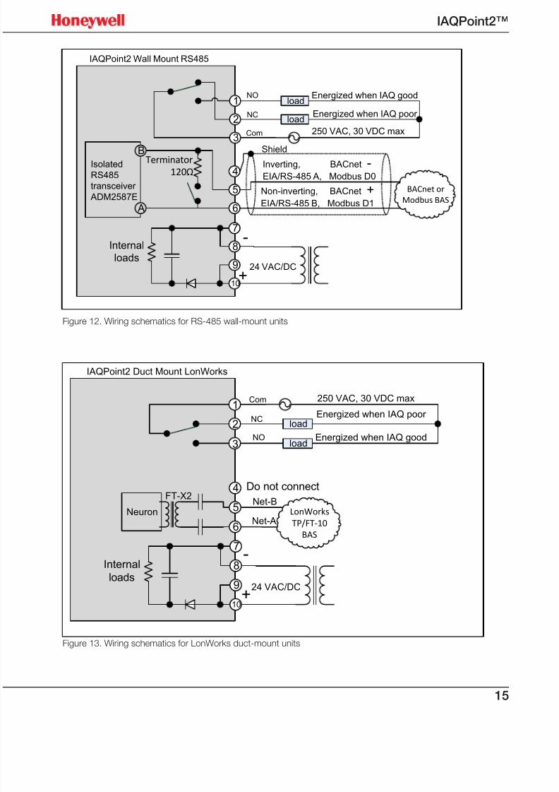
Figure 12. Wiring schematics for RS-485 wall-mount units
IAQPoint2 Duct Mount LonWorks
1
2
3NO
NC
Com
load
loadEnergized when IAQ good
Energized when IAQ poor
250 VAC, 30 VDC max
7
8
9
10
24 VAC/DC
Internal
loads
4
5
6
Net-BNeuron
FT-X2
Net-ALonWorks
TP/FT-10
BAS
Do not connect
-
+
Figure 13. Wiring schematics for LonWorks duct-mount units
IAQPoint2 Wall Mount RS485
7
8
9
10
24 VAC/DC
Internal
loads
1
2
3
NO
NC
Com
load
load
Energized when IAQ good
Energized when IAQ poor
250 VAC, 30 VDC max
4
5
6 A
B
Isolated
RS485
transceiver
ADM2587E
Terminator
120ΩInverting, BACnet -EIA/RS-485 A, Modbus D0
BACnet or
Modbus BAS
Non-inverting, BACnet +EIA/RS-485 B, Modbus D1
Shield
+
-
7/23/2019 IAQPoint2 Manual ENG Rev03
http://slidepdf.com/reader/full/iaqpoint2-manual-eng-rev03 18/8016
IAQPoint2™
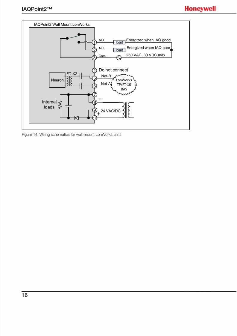
IAQPoint2 Wall Mount LonWorks
1
2
3
NO
NC
Com
load
load
Energized when IAQ good
Energized when IAQ poor
250 VAC, 30 VDC max
7
8
9
10
24 VAC/DC
Internal
loads
4
5
6
Net-BNeuron
FT-X2
Net-ALonWorks
TP/FT-10
BAS
Do not connect
-
+
Figure 14. Wiring schematics for wall-mount LonWorks units
7/23/2019 IAQPoint2 Manual ENG Rev03
http://slidepdf.com/reader/full/iaqpoint2-manual-eng-rev03 19/8017
IAQPoint2™
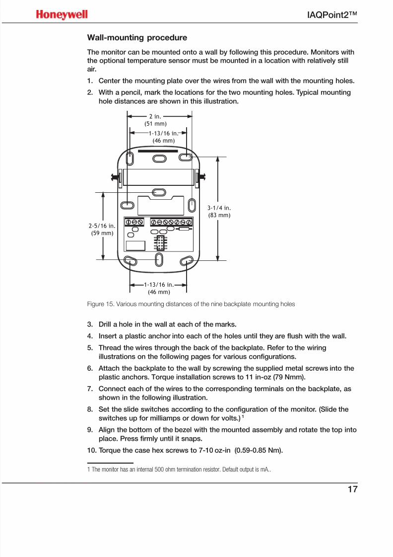
Wall-mounting procedure
The monitor can be mounted onto a wall by following this procedure. Monitors withthe optional temperature sensor must be mounted in a location with relatively still
air.
1. Center the mounting plate over the wires from the wall with the mounting holes.
2. With a pencil, mark the locations for the two mounting holes. Typical mounting
hole distances are shown in this illustration.
1-13/16 in.
(46 mm)
3-1/4 in.
(83 mm)
1-13/16 in.
(46 mm)
2 in.
(51 mm)
2-5/16 in.
(59 mm)
Figure 15. Various mounting distances of the nine backplate mounting holes
3. Drill a hole in the wall at each of the marks.
4. Insert a plastic anchor into each of the holes until they are flush with the wall.
5. Thread the wires through the back of the backplate. Refer to the wiring
illustrations on the following pages for various configurations.
6. Attach the backplate to the wall by screwing the supplied metal screws into the
plastic anchors. Torque installation screws to 11 in-oz (79 Nmm).
7. Connect each of the wires to the corresponding terminals on the backplate, asshown in the following illustration.
8. Set the slide switches according to the configuration of the monitor. (Slide the
switches up for milliamps or down for volts.)1
9. Align the bottom of the bezel with the mounted assembly and rotate the top into
place. Press firmly until it snaps.
10. Torque the case hex screws to 7-10 oz-in (0.59-0.85 Nm).
1 The monitor has an internal 500 ohm termination resistor. Default output is mA..
7/23/2019 IAQPoint2 Manual ENG Rev03
http://slidepdf.com/reader/full/iaqpoint2-manual-eng-rev03 20/8018
IAQPoint2™
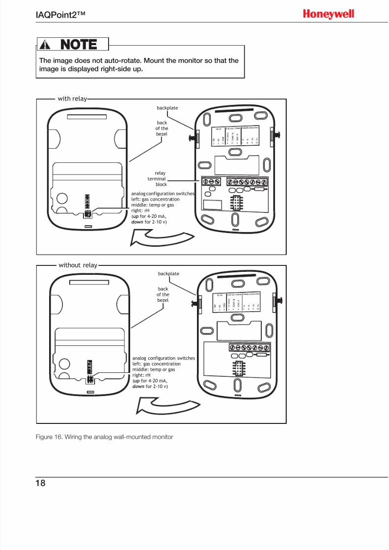
The image does not auto-rotate. Mount the monitor so that theimage is displayed right-side up.
NOTE!
with relay
backplate
backof thebezel
relay
terminalblock
backof thebezel
without relay
backplate
analog configuration switchesleft: gas concentrationmiddle: temp or gasright: rH
(up for 4-20 mA,down for 2-10 v)
analog configuration switchesleft: gas concentrationmiddle: temp or gasright: rH(up for 4-20 mA,
down for 2-10 v)
Figure 16. Wiring the analog wall-mounted monitor
7/23/2019 IAQPoint2 Manual ENG Rev03
http://slidepdf.com/reader/full/iaqpoint2-manual-eng-rev03 21/8019
IAQPoint2™
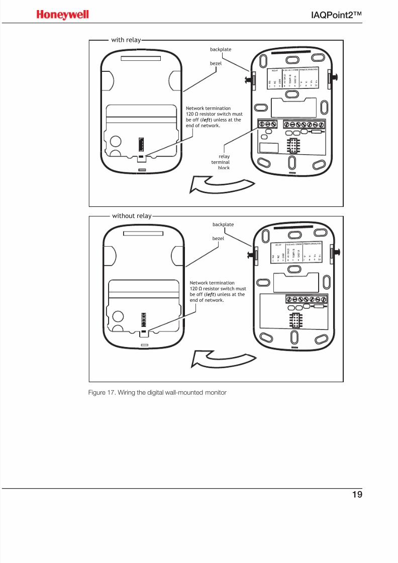
with relay
backplate
bezel
relay
terminal
block
Network termination
120 Ω resistor switch must
be off (left) unless at the
end of network.
Network termination
120 Ω resistor switch must
be off (left) unless at theend of network.
without relay
backplate
bezel
Figure 17. Wiring the digital wall-mounted monitor

7/23/2019 IAQPoint2 Manual ENG Rev03
http://slidepdf.com/reader/full/iaqpoint2-manual-eng-rev03 22/8020
IAQPoint2™
Duct-mounting procedure
The monitor can be mounted on a rectangular duct at least 7 in. × 7 in. (18 cm ×
18 cm) or a round duct at least 24 inches (61 cm) in diameter by two sheet metal
screws which are supplied in the installer’s kit. Do not mount the monitor on the top
or bottom of a duct. (The sampling tube is designed for horizontal installation.)
Installation kit:
• IAQPoint2 monitor
• backplate
• Two metal screws
• Quick Start Guide (one page, paper)
• Resource CD
Optional calibration kit (see page 11 for details)
Tools needed:
• drill
• hole saw
• drill bit
• #1, #2 Phillips, and 1/8 inch (3 mm) straight screwdrivers
• wire strippers
Procedure:
1. Make a 11 / 16–inch (27 mm) hole in the duct at the desired sampling location.
2. Position the duct-mount bracket over the hole.
3. With a pencil, mark the locations for the two mounting holes.
4. Drill a hole in the duct at each of the marks.5. Attach the mounting plate to the duct with the supplied sheet metal screws.
Torque the screws to 11 in-oz (79 Nmm).
6. Slide the sampling tube through the mounting bracket up to the collar (shown in
the following illustration).
Figure 18. Positioning the sampling tube in the mounting plate
7. Torque the case hex screws to screws to 7-10 oz-in (0.59-0.85 Nm).

7/23/2019 IAQPoint2 Manual ENG Rev03
http://slidepdf.com/reader/full/iaqpoint2-manual-eng-rev03 23/8021
IAQPoint2™
collar
gasket
gasket
intake/
exhaust
mounting plate
sampling tube
connector
mounting
plate clamp
O-ring
cross-sections in
vertical ducts
air flow
connector orientations
cross-sections in
horizontal ducts
air flow air flowair flow
Figure 19. Sampling tube and mounting plate
8. Rotate the sampling tube until the divider shown in the cross-section illustration
above is perpendicular to the flow of air in the duct.
9. Lightly lubricate the connector O-ring with water to facilitate installation.
10. Position the connector on the back of the monitor on the sampling tube
connector and twist a quarter-turn counter-clockwise. A tight fit is normal (the
O-ring on the sampling tube provides a snug seal with the monitor). The monitor
will snap into position when it is securely attached to the sampling tube.
The display does not auto-rotate. Mount the monitor so thatthe display is right-side up and wires enter the two conduit
holes from the bottom.
NOTE!
11. Tighten the mounting plate clamp screws.
12. Conduit is attached to the bottom of the monitor in the same manner as
standard electrical junction boxes. Refer to the wiring illustrations on the
following pages for various configurations.
13. Install the terminal block cover.
7/23/2019 IAQPoint2 Manual ENG Rev03
http://slidepdf.com/reader/full/iaqpoint2-manual-eng-rev03 24/8022
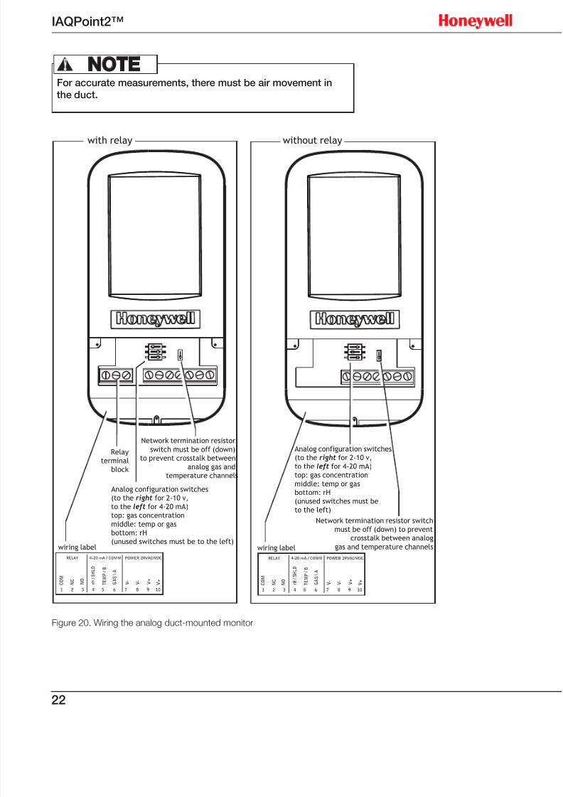
IAQPoint2™
For accurate measurements, there must be air movement inthe duct.
NOTE!
Network termination resistor switch
must be off (down) to prevent
crosstalk between analog
gas and temperature channelswiring label
without relay
4-20 mA / COMMRELAY POWER 24VAC/VDC
N O
N C
C O M
r H /
S H L D
T E M P / B
G A S \ A
V -
V -
V +
V +
1 2 3 4 5 6 7 8 9 10
Analog configuration switches
(to the right for 2-10 v,
to the left for 4-20 mA)
top: gas concentration
middle: temp or gas
bottom: rH
(unused switches must be to the left)
Network termination resistor
switch must be off (down)
to prevent crosstalk between
analog gas and
temperature channels
Relay
terminal
block
wiring label
4-20 mA / COMMRELAY POWER 24VAC/VDC
N O
N C
C O M
r H /
S H L D
T E M P / B
G A S \ A
V -
V -
V +
V +
1 2 3 4 5 6 7 8 9 10
with relay
Analog configuration switches
(to the right for 2-10 v,
to the left for 4-20 mA)
top: gas concentration
middle: temp or gas
bottom: rH
(unused switches must be
to the left)
Figure 20. Wiring the analog duct-mounted monitor
7/23/2019 IAQPoint2 Manual ENG Rev03
http://slidepdf.com/reader/full/iaqpoint2-manual-eng-rev03 25/8023
IAQPoint2™
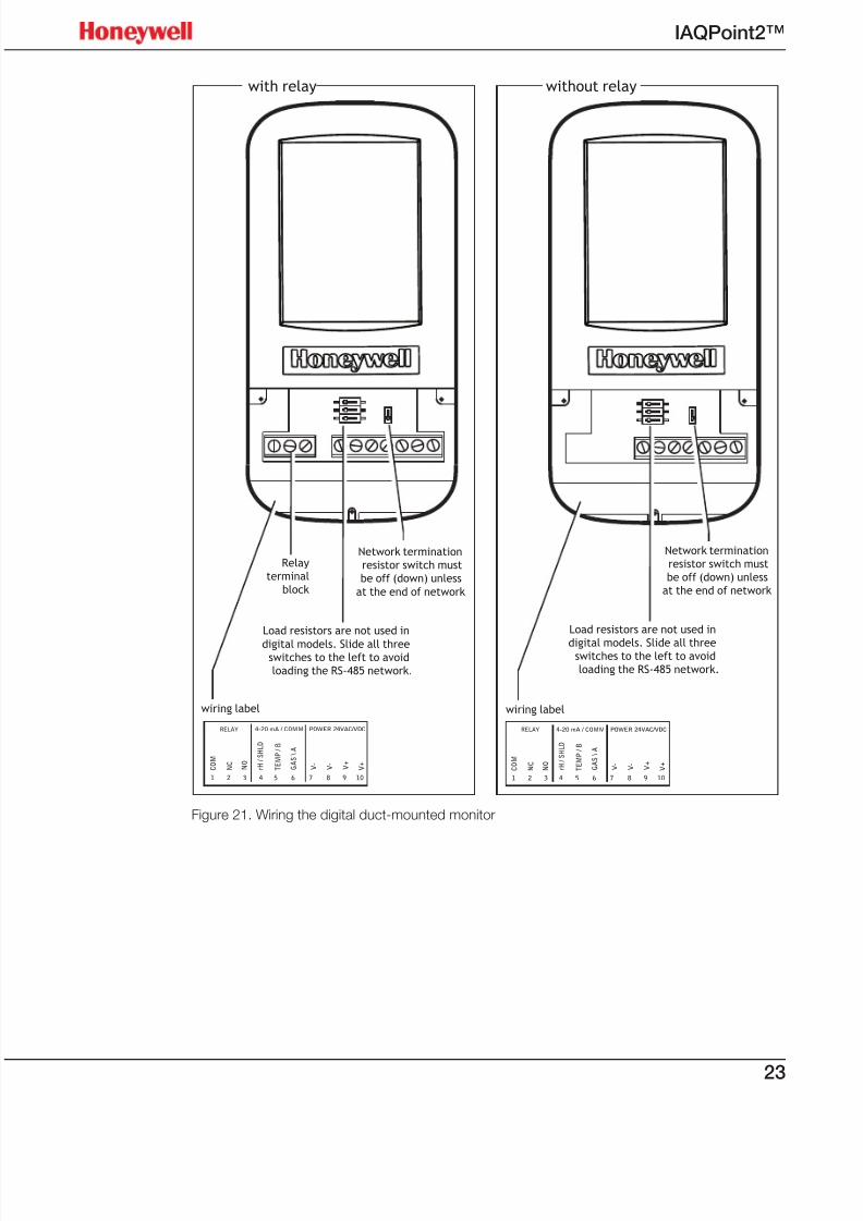
wiring label
Relay
terminal
block
with relay
Network termination
resistor switch must
be off (down) unless
at the end of network
Load resistors are not used in
digital models. Slide all threeswitches to the left to avoid
loading the RS-485 network.
4-20 mA / COMMRELAY POWER 24VAC/VDC
N O
N C
C O M
r H /
S H L D
T E M P / B
G A S \ A
V -
V -
V +
V +
1 2 3 4 5 6 7 8 9 10
wiring label
without relay
4-20 mA / COMMRELAY POWER 24VAC/VDC
N O
N C
C O M
r H /
S H L D
T E M P / B
G A S \ A
V -
V -
V +
V +
1 2 3 4 5 6 7 8 9 10
Network termination
resistor switch must
be off (down) unless
at the end of network
Load resistors are not used in
digital models. Slide all threeswitches to the left to avoid
loading the RS-485 network.
Figure 21. Wiring the digital duct-mounted monitor

7/23/2019 IAQPoint2 Manual ENG Rev03
http://slidepdf.com/reader/full/iaqpoint2-manual-eng-rev03 26/8024
IAQPoint2™
Operation
First power-up
No calibration of the CO2 or VOC sensors is required at startup. The monitor will
immediately begin operation with the default parameters discussed in the Menus section. If desired, the monitor can be calibrated, however. Calibration procedures
are described beginning on page 44.
Expect some slight variability in the monitor’s output wheninitially powered up. The sensors will fully stabilize after two to
three weeks.
NOTE!
Commissioning
CO 2 Configurations
With Automatic Baseline Correction (ABC) enabled
When the monitor is first powered up with ABC enabled (the default is ABC on),no calibration is required. ABC monitors the background CO2 levels and makesadjustments to the baseline calibration once every 24 hours. Within three weeks,the CO2 sensor will adjust to the environment and be performing at the specified
accuracy. No further adjustment or calibration of the CO2 sensor is required.
With ABC disabled
This section applies to display models only. For applications in which ABC is
disabled, the monitor must be calibrated at least annually to accommodate anydrift due to the environment in which it is installed and to compensate for the
sensor electronics.
When the monitor is first powered up with ABC disabled, allow it to operate for 24hours in the environment in which it will be used. If necessary, check the accuracyof the sensor by applying a known concentration of test gas, following the
instructions in this manual for proper calibration procedures.
Temperature and relative humidity
The monitor’s internal temperature will stabilize about twenty minutes after first
being powered up. The monitor provides the capability to calibrate temperatureand humidity sensor readings. If, after the system has stabilized, it is determinedthat a temperature offset is required, follow the instructions in this manual for
proper calibration procedures. VOC Configurations
The VOC sensor used with the IAQPoint2 monitor requires no calibration but allow
it fifteen minutes to warm up each time power is applied. The sensor will use theair in which it is powered up as the baseline. The VOC sensor will adapt to theenvironment in which it is installed.
7/23/2019 IAQPoint2 Manual ENG Rev03
http://slidepdf.com/reader/full/iaqpoint2-manual-eng-rev03 27/8025
IAQPoint2™
If the monitor is installed in an area with a chronically high
level of VOCs, it will use that level to establish its baseline. Itwill then report a high VOC level only when the concentrationrises above this baseline. It will recalibrate the baseline when
chronic VOCs are abated.
NOTE!
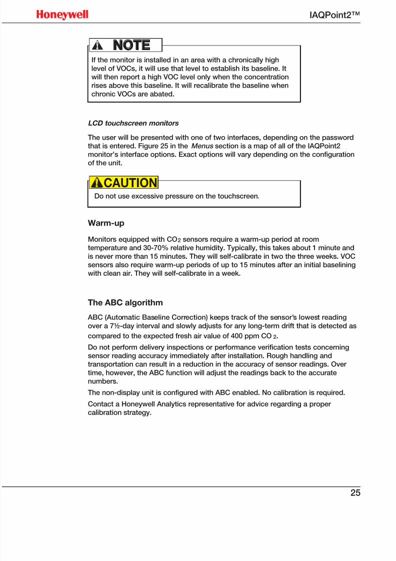
LCD touchscreen monitors
The user will be presented with one of two interfaces, depending on the passwordthat is entered. Figure 25 in the Menus section is a map of all of the IAQPoint2monitor’s interface options. Exact options will vary depending on the configurationof the unit.
Do not use excessive pressure on the touchscreen.
CAUTION!
Warm-up
Monitors equipped with CO2 sensors require a warm-up period at roomtemperature and 30-70% relative humidity. Typically, this takes about 1 minute and
is never more than 15 minutes. They will self-calibrate in two the three weeks. VOCsensors also require warm-up periods of up to 15 minutes after an initial baseliningwith clean air. They will self-calibrate in a week.
The ABC algorithm
ABC (Automatic Baseline Correction) keeps track of the sensor’s lowest reading
over a 7½-day interval and slowly adjusts for any long-term drift that is detected as
compared to the expected fresh air value of 400 ppm CO2.
Do not perform delivery inspections or performance verification tests concerningsensor reading accuracy immediately after installation. Rough handling andtransportation can result in a reduction in the accuracy of sensor readings. Over
time, however, the ABC function will adjust the readings back to the accuratenumbers.
The non-display unit is configured with ABC enabled. No calibration is required.Contact a Honeywell Analytics representative for advice regarding a propercalibration strategy.
7/23/2019 IAQPoint2 Manual ENG Rev03
http://slidepdf.com/reader/full/iaqpoint2-manual-eng-rev03 28/8026
IAQPoint2™
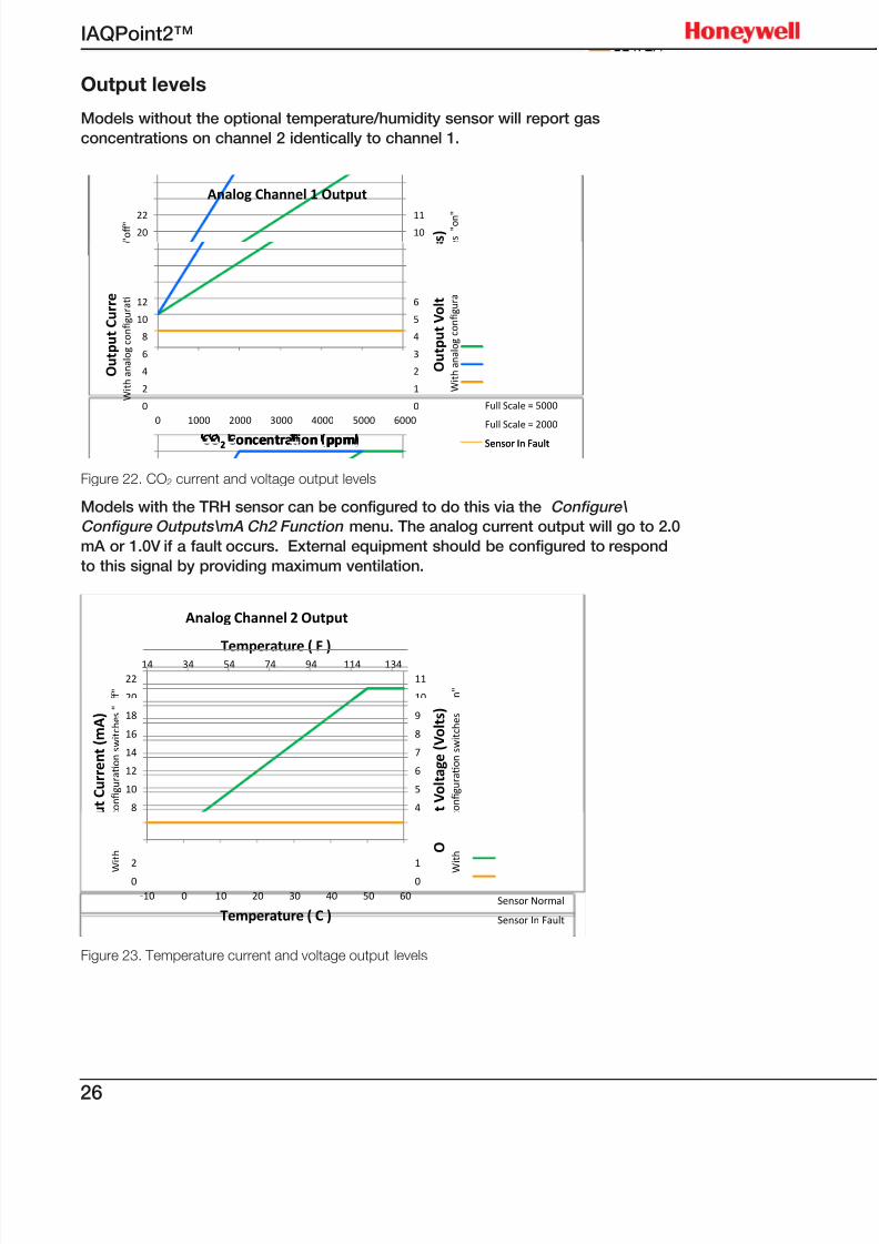
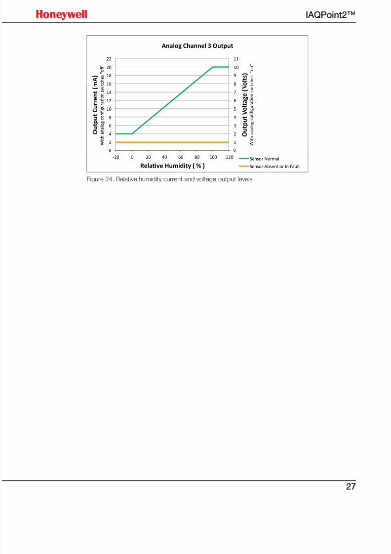
Output levels
Models without the optional temperature/humidity sensor will report gas
concentrations on channel 2 identically to channel 1.
Relav
Humidi
(%)
Tempe
rature
(F )
Tempe
rature
(C )
Gas
Conce
ntrao
n
Output
Curren
t (mA)
if
Output
Curren
t (mA)
if
In
Fault
Output
Voltag
e
(Volts)
Output
Voltag
e
(Volts)
-40 -10 4 4 2
-20 14 -10 0 4 4 2 30 2
5
6
7
8
9
1011
10
12
14
16
18
2022
V o l t a g e ( V o l t s )
n fi g u r a t o n
s w i t c h e s " o n
"
C u r r e n t ( m A )
i g u r a t o n s w i t c h e s " o ff "
Analog Channel 1 Output
0 32 0 0 4 4 2 30 2
40 68 20 2000 10.4 20 2 30 10
100 122 50 5000 20 20 2 30 10
120 140 60 6000 20 20 2 30
0
1
2
3
4
5
6
0
2
4
6
8
10
12
0 1000 2000 3000 4000 5000 6000
O u t p u t V o l t
W i t h a n a l o g c o n fi g u r a
O u t p u t C u r r e
W i t h a n a l o g c o n fi g u r a t
CO2 Concentraton (ppm)
Full Scale = 5000
Full Scale = 2000
Sensor In Fault2 oncentra on ppm Sensor In Fault
Figure 22. CO2 current and voltage output levels
Models with the TRH sensor can be configured to do this via the Configure\
Configure Outputs\mA Ch2 Function menu. The analog current output will go to 2.0
mA or 1.0V if a fault occurs. External equipment should be configured to respond
to this signal by providing maximum ventilation.
14 34 54 74 94 114 134
8
9
10
11
16
18
20
22
Temperature ( F )
V o l t s )
w i t c h e s " o n "
m A )
w i t c h e s " o ff "
Analog Channel 2 Output
0
1
2
3
4
5
6
7
8
9
0
2
4
6
8
10
12
14
16
18
O u t p u t V o l t a g e ( V o l t s )
W
i t h a n a l o g c o n fi g u r a t o n
s w i t c h e s
O u t p u t C u r r e n t ( m A )
W
i t h a n a l o g c o n fi g u r a t o n
s w i t c h e s "
0
1
0
2
-10 0 10 20 30 40 50 60
O
W
i t h
W
i t h
Temperature ( C )Sensor Normal
Sensor In Fault
Figure 23. Temperature current and voltage output levels
7/23/2019 IAQPoint2 Manual ENG Rev03
http://slidepdf.com/reader/full/iaqpoint2-manual-eng-rev03 29/8027
IAQPoint2™
7
8
9
10
11
14
16
18
20
22
g e ( V o l t s )
t i o n s w i t c h e s " o n "
e n t ( m A )
t i o n s w i t c h e s " o ff "
Analog Channel 3 Output
0
1
2
3
4
5
6
7
0
2
4
6
8
10
12
14
-20 0 20 40 60 80 100 120
O u t p u t V o l t a g e (
W i t h a n a l o g c o n fi g u r a t o n
s w
O u t p u t C u r r e n t (
W i t h a n a l o g c o n fi g u r a t o
n
s w
Sensor Normal-20 0 20 40 60 80 100 120
Relatve Humidity ( % )
Sensor Normal
Sensor Absent or In Fault
Figure 24. Relative humidity current and voltage output levels
7/23/2019 IAQPoint2 Manual ENG Rev03
http://slidepdf.com/reader/full/iaqpoint2-manual-eng-rev03 30/8028
IAQPoint2™
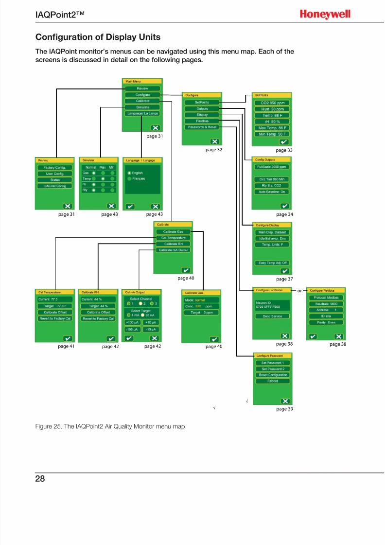
Conguration of Display Units
The IAQPoint monitor’s menus can be navigated using this menu map. Each of the
screens is discussed in detail on the following pages.
Figure 25. The IAQPoint2 Air Quality Monitor menu map
√
√
page 31
page 32 page 33
page 34
page 37
page 38
page 39
page 40page 42page 41
page 43
page 40
page 43page 31
page 42
or
page 38
7/23/2019 IAQPoint2 Manual ENG Rev03
http://slidepdf.com/reader/full/iaqpoint2-manual-eng-rev03 31/8029
IAQPoint2™
The contents of some menus vary depending on the configuration of the monitorand on which password was entered. Those variations are noted in the appropriatesections.
Menu naming conventions
Menus are navigated by pressing the appropriate buttons. Active buttons areindicated by yellow borders. These buttons will be identified by placing them in
brackets, for example, if the instruction is “Select [Configure]”, press the buttonwhich contains the word “Configure”.
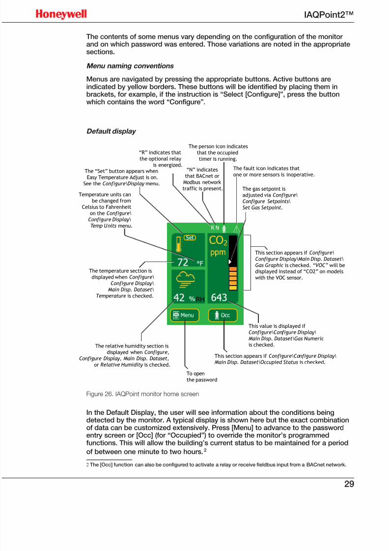
Default display
Figure 26. IAQPoint monitor home screen
In the Default Display, the user will see information about the conditions beingdetected by the monitor. A typical display is shown here but the exact combinationof data can be customized extensively. Press [Menu] to advance to the passwordentry screen or [Occ] (for “Occupied”) to override the monitor’s programmedfunctions. This will allow the building’s current status to be maintained for a period
of between one minute to two hours.2
2 The [Occ] function can also be configured to activate a relay or receive fieldbus input from a BACnet network.
196 mm.
RH
The relative humidity section is
displayed when Configure,
Configure Display, Main Disp. Dataset,
or Relative Humidity is checked.
The temperature section is
displayed when Configure\
Configure Display\
Main Disp. Dataset\Temperature is checked.
Temperature units canbe changed from
Celsius to Fahrenheit
on the Configure\
Configure Display\
Temp Units menu.
The “Set” button appears when
Easy Temperature Adjust is on.
See the Configure\Display menu.
“R” indicates that
the optional relay
is energized.“N” indicates
that BACnet or
Modbus network
traffic is present.
The person icon indicates
that the occupied
timer is running.
The fault icon indicates that
one or more sensors is inoperative.
The gas setpoint is
adjusted via Configure\Configure Setpoints\
Set Gas Setpoint.
This section appears if Configure\
Configure Display\Main Disp. Dataset\
Gas Graphic is checked. “VOC” will bedisplayed instead of “CO2” on models
with the VOC sensor.
This value is displayed if
Configure\Configure Display\
Main Disp. Dataset\Gas Numericis checked.
This section appears if Configure\Configure Display\Main Disp. Dataset\Occupied Status is checked.
To open
the password
7/23/2019 IAQPoint2 Manual ENG Rev03
http://slidepdf.com/reader/full/iaqpoint2-manual-eng-rev03 32/8030
IAQPoint2™
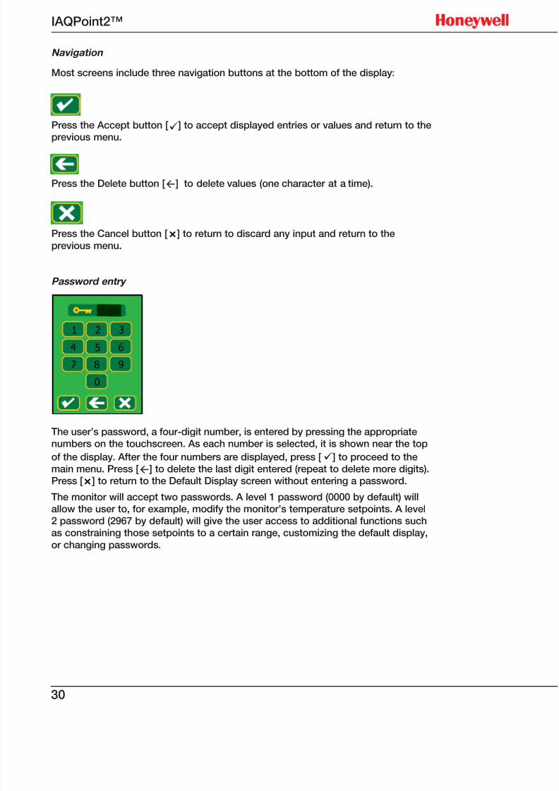
Navigation
Most screens include three navigation buttons at the bottom of the display:
Press the Accept button [ü] to accept displayed entries or values and return to the
previous menu.
Press the Delete button [ß] to delete values (one character at a time).
Press the Cancel button [Ñ] to return to discard any input and return to the
previous menu.
Password entry
1 32
4 65
7 98
0
√
The user’s password, a four-digit number, is entered by pressing the appropriatenumbers on the touchscreen. As each number is selected, it is shown near the top
of the display. After the four numbers are displayed, press [ü] to proceed to themain menu. Press [ß] to delete the last digit entered (repeat to delete more digits).Press [Ñ] to return to the Default Display screen without entering a password.
The monitor will accept two passwords. A level 1 password (0000 by default) willallow the user to, for example, modify the monitor’s temperature setpoints. A level2 password (2967 by default) will give the user access to additional functions suchas constraining those setpoints to a certain range, customizing the default display,
or changing passwords.
7/23/2019 IAQPoint2 Manual ENG Rev03
http://slidepdf.com/reader/full/iaqpoint2-manual-eng-rev03 33/8031
IAQPoint2™
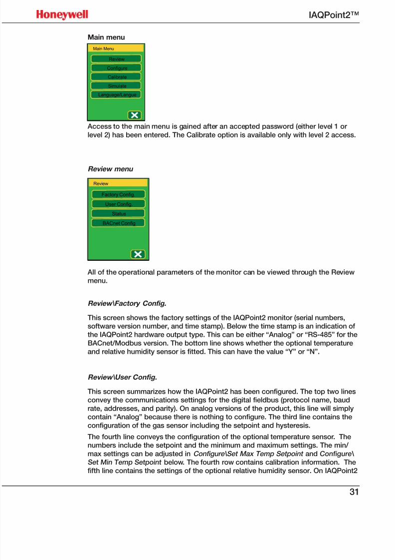
Main menu
Main Menu
Review
Configure
Calibrate
Simulate
Language/Langue
Access to the main menu is gained after an accepted password (either level 1 or
level 2) has been entered. The Calibrate option is available only with level 2 access.
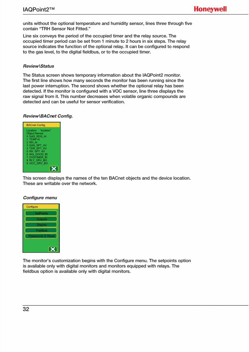
Review menu
Review
Factory Config.
User Config.
Status
BACnet Config
All of the operational parameters of the monitor can be viewed through the Reviewmenu.
Review\Factory Config.
This screen shows the factory settings of the IAQPoint2 monitor (serial numbers,software version number, and time stamp). Below the time stamp is an indication ofthe IAQPoint2 hardware output type. This can be either “Analog” or “RS-485” for the
BACnet/Modbus version. The bottom line shows whether the optional temperatureand relative humidity sensor is fitted. This can have the value “Y” or “N”.
Review\ User Config.
This screen summarizes how the IAQPoint2 has been configured. The top two linesconvey the communications settings for the digital fieldbus (protocol name, baudrate, addresses, and parity). On analog versions of the product, this line will simplycontain “Analog” because there is nothing to configure. The third line contains the
configuration of the gas sensor including the setpoint and hysteresis.
The fourth line conveys the configuration of the optional temperature sensor. Thenumbers include the setpoint and the minimum and maximum settings. The min/
max settings can be adjusted in Configure\Set Max Temp Setpoint and Configure\
Set Min Temp Setpoint below. The fourth row contains calibration information. Thefifth line contains the settings of the optional relative humidity sensor. On IAQPoint2
7/23/2019 IAQPoint2 Manual ENG Rev03
http://slidepdf.com/reader/full/iaqpoint2-manual-eng-rev03 34/8032
IAQPoint2™
units without the optional temperature and humidity sensor, lines three through fivecontain “TRH Sensor Not Fitted.”
Line six conveys the period of the occupied timer and the relay source. Theoccupied timer period can be set from 1 minute to 2 hours in six steps. The relaysource indicates the function of the optional relay. It can be configured to respond
to the gas level, to the digital fieldbus, or to the occupied timer.
Review\Status
The Status screen shows temporary information about the IAQPoint2 monitor.The first line shows how many seconds the monitor has been running since the
last power interruption. The second shows whether the optional relay has beendetected. If the monitor is configured with a VOC sensor, line three displays theraw signal from it. This number decreases when volatile organic compounds aredetected and can be useful for sensor verification.
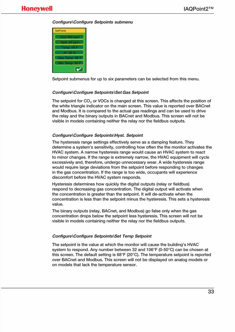
Review\BACnet Config.
BACnet Config.
Location “location”Object Names0 GAS_RDG_AI1 TEMP AI2 RH_AI3 GAS_SPT_AV4 TEM_SPT_AV5 RH_SPT_AV6 IAQ_GOOD_BI7 OVDTIMER_BI8 RLY_DRV_BO9 OCC_DRV_BO
This screen displays the names of the ten BACnet objects and the device location.
These are writable over the network.
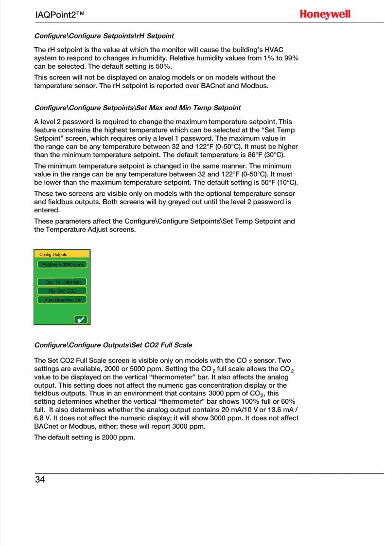
Configure menu
Configure
SetPoints
Outputs
Display
Fieldbus
Passwords & Reset
The monitor’s customization begins with the Configure menu. The setpoints option
is available only with digital monitors and monitors equipped with relays. Thefieldbus option is available only with digital monitors.
7/23/2019 IAQPoint2 Manual ENG Rev03
http://slidepdf.com/reader/full/iaqpoint2-manual-eng-rev03 35/8033
IAQPoint2™
Configure\Configure Setpoints submenu
SetPoints
CO2 850 ppm
Hyst 50 ppm
Temp 68 F
rH 50 %
Max Temp 86 F
Min Temp 50 F
√
Setpoint submenus for up to six parameters can be selected from this menu.
Configure\Configure Setpoints\Set Gas Setpoint
The setpoint for CO2 or VOCs is changed at this screen. This affects the position ofthe white triangle indicator on the main screen. This value is reported over BACnetand Modbus. It is compared to the actual gas readings and can be used to drive
the relay and the binary outputs in BACnet and Modbus. This screen will not bevisible in models containing neither the relay nor the fieldbus outputs.
Configure\Configure Setpoints\Hyst. Setpoint
The hysteresis range settings effectively serve as a damping feature. Theydetermine a system’s sensitivity, controlling how often the the monitor activates theHVAC system. A narrow hysteresis range would cause an HVAC system to react
to minor changes. If the range is extremely narrow, the HVAC equipment will cycleexcessively and, therefore, undergo unnecessary wear. A wide hysteresis rangewould require large deviations from the setpoint before responding to changes
in the gas concentration. If the range is too wide, occupants will experiencediscomfort before the HVAC system responds.
Hysteresis determines how quickly the digital outputs (relay or fieldbus)respond to decreasing gas concentration. The digital output will activate when
the concentration is greater than the setpoint. It will de-activate when theconcentration is less than the setpoint minus the hysteresis. This sets a hysteresisvalue.
The binary outputs (relay, BACnet, and Modbus) go false only when the gasconcentration drops below the setpoint less hysteresis. This screen will not bevisible in models containing neither the relay nor the fieldbus outputs.
Configure\Configure Setpoints\Set Temp Setpoint
The setpoint is the value at which the monitor will cause the building’s HVACsystem to respond. Any number between 32 and 106°F (0-50°C) can be chosen atthis screen. The default setting is 68°F (20°C). The temperature setpoint is reported
over BACnet and Modbus. This screen will not be displayed on analog models oron models that lack the temperature sensor.
7/23/2019 IAQPoint2 Manual ENG Rev03
http://slidepdf.com/reader/full/iaqpoint2-manual-eng-rev03 36/8034
IAQPoint2™
Configure\Configure Setpoints\rH Setpoint
The rH setpoint is the value at which the monitor will cause the building’s HVAC
system to respond to changes in humidity. Relative humidity values from 1% to 99%can be selected. The default setting is 50%.
This screen will not be displayed on analog models or on models without the
temperature sensor. The rH setpoint is reported over BACnet and Modbus.
Configure\Configure Setpoints\Set Max and Min Temp Setpoint
A level 2 password is required to change the maximum temperature setpoint. Thisfeature constrains the highest temperature which can be selected at the “Set Temp
Setpoint” screen, which requires only a level 1 password. The maximum value inthe range can be any temperature between 32 and 122°F (0-50°C). It must be higherthan the minimum temperature setpoint. The default temperature is 86°F (30°C).
The minimum temperature setpoint is changed in the same manner. The minimumvalue in the range can be any temperature between 32 and 122°F (0-50°C). It mustbe lower than the maximum temperature setpoint. The default setting is 50°F (10°C).
These two screens are visible only on models with the optional temperature sensorand fieldbus outputs. Both screens will by greyed out until the level 2 password isentered.
These parameters affect the Configure\Configure Setpoints\Set Temp Setpoint andthe Temperature Adjust screens.
Config Outputs
FullScale 2000 ppm
Occ Tmr 060 Min
Rly Src: CO2
Auto Baseline: On
Configure\Configure Outputs\Set CO2 Full Scale
The Set CO2 Full Scale screen is visible only on models with the CO2 sensor. Twosettings are available, 2000 or 5000 ppm. Setting the CO2 full scale allows the CO2
value to be displayed on the vertical “thermometer” bar. It also affects the analog
output. This setting does not affect the numeric gas concentration display or thefieldbus outputs. Thus in an environment that contains 3000 ppm of CO2, thissetting determines whether the vertical “thermometer” bar shows 100% full or 60%full. It also determines whether the analog output contains 20 mA/10 V or 13.6 mA /
6.8 V. It does not affect the numeric display; it will show 3000 ppm. It does not affectBACnet or Modbus, either; these will report 3000 ppm.
The default setting is 2000 ppm.
7/23/2019 IAQPoint2 Manual ENG Rev03
http://slidepdf.com/reader/full/iaqpoint2-manual-eng-rev03 37/8035
IAQPoint2™
Configure\Configure Outputs\Set mA Ch2 Function
The IAQPoint monitor has three channels. Channels 1 and 2 report gas values.Channel 2 can be configured to measure temperature (voltage) instead. Channel 3measures humidity when the optional rH sensor is installed. Report Temperatureis the default when the monitor is configured with a temperature/humidity sensor,
otherwise Report Gas Conc. is the default.
The operation of the middle of the three analog outputs is determined at thisscreen. (It will not be visible on digital models.) Models without the optional
temperature sensor route the gas signal to channel 2 by default and so do notshow this screen. Thus this screen is visible only on models with analog output anda temperature sensor.
This screen permits changing the function of channel two. For example, a certainmonitor might be in an environment with a CO2 concentration of 5000 ppm (fullscale) and a temperature of 77°F (half scale). If the channel 2 function is set totemperature, the 12 mA/6 V (temperature) signal will be produced by channel 2.
But if the channel 2 function is set to CO2, the 20 mA/10 V (the CO2 signal) will beproduced by channel 2. This feature works in a similar fashion if a VOC sensor is
fitted. It has no effect on the operation of channels 1 or 3. This facilitates gettingfrom a single monitor both current and voltage signals that are proportional to theCO2 concentration.
Configure\Configure Outputs\Set Occupied Timeout
Set Occupied Timeout controls the delay between when the HVAC system is given
the command to deactivate and when it actually shuts down. Available valuesvary from one minute to two hours in six steps. The occupied timer starts runningwhenever the [Occ] button on the main screen is pressed. (The [Occ] button is
hidden by default but can be shown via Configure\Configure Display\Main Display
Datase t.) The timer drives the “occupied” icon ( ) on the main screen, a fieldbusoutput, and can be configured to drive the relay. (The relay is configured via theConfigure\Configure Outputs\Set Relay Source screen.)
7/23/2019 IAQPoint2 Manual ENG Rev03
http://slidepdf.com/reader/full/iaqpoint2-manual-eng-rev03 38/8036
IAQPoint2™
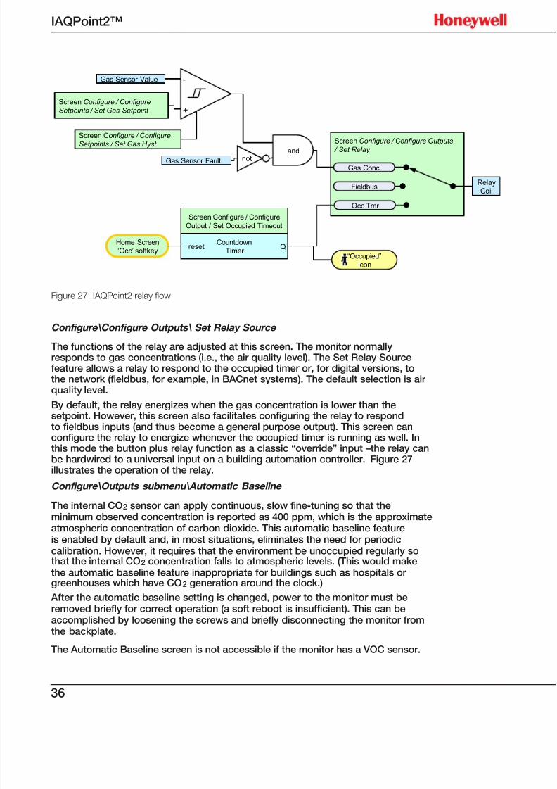
Figure 27. IAQPoint2 relay ow
Configure\Configure Outputs\ Set Relay Source
The functions of the relay are adjusted at this screen. The monitor normallyresponds to gas concentrations (i.e., the air quality level). The Set Relay Sourcefeature allows a relay to respond to the occupied timer or, for digital versions, tothe network (fieldbus, for example, in BACnet systems). The default selection is airquality level.
By default, the relay energizes when the gas concentration is lower than the
setpoint. However, this screen also facilitates configuring the relay to respondto fieldbus inputs (and thus become a general purpose output). This screen canconfigure the relay to energize whenever the occupied timer is running as well. Inthis mode the button plus relay function as a classic “override” input –the relay canbe hardwired to a universal input on a building automation controller. Figure 27illustrates the operation of the relay.
Configure\Outputs submenu\Automatic Baseline
The internal CO2 sensor can apply continuous, slow fine-tuning so that theminimum observed concentration is reported as 400 ppm, which is the approximateatmospheric concentration of carbon dioxide. This automatic baseline featureis enabled by default and, in most situations, eliminates the need for periodic
calibration. However, it requires that the environment be unoccupied regularly sothat the internal CO2 concentration falls to atmospheric levels. (This would make
the automatic baseline feature inappropriate for buildings such as hospitals orgreenhouses which have CO2 generation around the clock.)
After the automatic baseline setting is changed, power to the monitor must beremoved briefly for correct operation (a soft reboot is insufficient). This can beaccomplished by loosening the screws and briefly disconnecting the monitor fromthe backplate.
The Automatic Baseline screen is not accessible if the monitor has a VOC sensor.
Screen Configure / Configure Outputs
/ Set Relay
Relay
Coil
Home Screen
‘Occ’ softkey
Screen Configure / Configure
Setpoints / Set Gas Setpoint
Gas Sensor Value
“Occupied”
icon
Gas Sensor FaultGas Conc.
Fieldbus
Occ Tmr
Screen Configure / ConfigureSetpoints / Set Gas Hyst and
-
+
Screen Configure / Configure
Output / Set Occupied Timeout
Countdown
Timerreset Q
not
7/23/2019 IAQPoint2 Manual ENG Rev03
http://slidepdf.com/reader/full/iaqpoint2-manual-eng-rev03 39/8037
IAQPoint2™
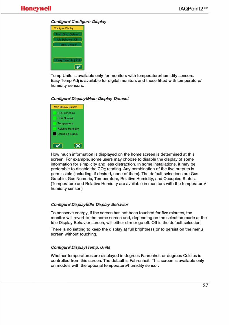
Configure\Configure Display
Configure Display
Main Disp. Dataset
Idle Behavior: Dim
Temp. Units: F
Easy Temp Adj: Off
Temp Units is available only for monitors with temperature/humidity sensors.Easy Temp Adj is available for digital monitors and those fitted with temperature/
humidity sensors.
Configure\Display\Main Display Dataset
Main Display Dataset
CO2 Graphics
CO2 Numeric
Temperature
Relative Humidity
Occupied Status
How much information is displayed on the home screen is determined at this
screen. For example, some users may choose to disable the display of someinformation for simplicity and less distraction. In some installations, it may be
preferable to disable the CO2 reading. Any combination of the five outputs ispermissible (including, if desired, none of them). The default selections are GasGraphic, Gas Numeric, Temperature, Relative Humidity, and Occupied Status.
(Temperature and Relative Humidity are available in monitors with the temperature/ humidity sensor.)
Configure\Display\Idle Display Behavior
To conserve energy, if the screen has not been touched for five minutes, themonitor will revert to the home screen and, depending on the selection made at theIdle Display Behavior screen, will either dim or go off. Off is the default selection.
There is no setting to keep the display at full brightness or to persist on the menuscreen without touching.
Configure\Display\ Temp. Units
Whether temperatures are displayed in degrees Fahrenheit or degrees Celcius is
controlled from this screen. The default is Fahrenheit. This screen is available onlyon models with the optional temperature/humidity sensor.
7/23/2019 IAQPoint2 Manual ENG Rev03
http://slidepdf.com/reader/full/iaqpoint2-manual-eng-rev03 40/8038
IAQPoint2™
Configure\Configure Display\Easy Temp Adj
If desired, a “Set” button can be displayed on the main menu, allowing thetemperature setpoint to be changed without entering a password. By default, thisfeature is disabled. This feature is disabled by default and is only available onmodels with the temperature sensor and the BACnet/Modbus interface.
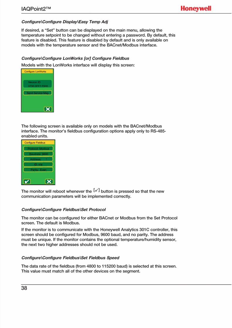
Configure\Configure LonWorks [or] Configure Fieldbus
Models with the LonWorks interface will display this screen:
Configure LonWorks
Neuron ID
Send Service Msg.
0700 0FF7 F600
The following screen is available only on models with the BACnet/Modbusinterface. The monitor’s fieldbus configuration options apply only to RS-485-enabled units.
Configure Fieldbus
Protocol: Modbus
Baudrate: 9600
Address: 1
ID: n/a
Parity: Even
The monitor will reboot whenever the [ü] button is pressed so that the new
communication parameters will be implemented correctly.
Configure\Configure Fieldbus\Set Protocol
The monitor can be configured for either BACnet or Modbus from the Set Protocolscreen. The default is Modbus.
If the monitor is to communicate with the Honeywell Analytics 301C controller, thisscreen should be configured for Modbus, 9600 baud, and no parity. The addressmust be unique. If the monitor contains the optional temperature/humidity sensor,
the next two higher addresses should not be used.
Configure\Configure Fieldbus\Set Fieldbus Speed
The data rate of the fieldbus (from 4800 to 115200 baud) is selected at this screen.This value must match all of the other devices on the segment.
7/23/2019 IAQPoint2 Manual ENG Rev03
http://slidepdf.com/reader/full/iaqpoint2-manual-eng-rev03 41/8039
IAQPoint2™
Configure\Configure Fieldbus\Set Address
If the BACnet protocol is selected, this screen facilitates setting the BACnet MACaddress from 1 to 127. If the Modbus protocol is selected, it facilitates setting theModbus ID from 1 to 247. The address must be unique within the segment.
Configure\Configure Fieldbus\Set BACnet ID
The BACnet ID can be adjusted to any value between 1 and 4,194,302 with thenumeric keyboard. The default value is 1. The Set BACnet ID menu applies onlyif the BACnet protocol is selected. This number must be unique within the entirenetwork. A network may consist of multiple segments separated by routers. Values
from 0 to 4194302 may be entered.
Configure\Fieldbus\Set Parity
Parity value selections apply only to monitors configured with the Modbus
communications protocol. Even parity is the default.
This parity screen is available only if the Modbus protocol is selected. (BACnetalways uses no parity.) The monitor will use one stop bit unless the parity is set to
“none” in which case it will use two stop bits.
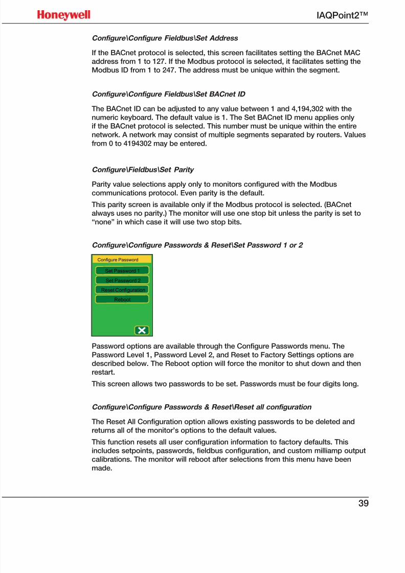
Configure\Configure Passwords & Reset\Set Password 1 or 2
Configure Password
Set Password 1
Set Password 2
Reset Configuration
Reboot
Password options are available through the Configure Passwords menu. The
Password Level 1, Password Level 2, and Reset to Factory Settings options aredescribed below. The Reboot option will force the monitor to shut down and thenrestart.
This screen allows two passwords to be set. Passwords must be four digits long.
Configure\Configure Passwords & Reset\Reset all configuration
The Reset All Configuration option allows existing passwords to be deleted andreturns all of the monitor’s options to the default values.
This function resets all user configuration information to factory defaults. Thisincludes setpoints, passwords, fieldbus configuration, and custom milliamp outputcalibrations. The monitor will reboot after selections from this menu have been
made.

7/23/2019 IAQPoint2 Manual ENG Rev03
http://slidepdf.com/reader/full/iaqpoint2-manual-eng-rev03 42/8040
IAQPoint2™
Configure\Configure Passwords & Reset\Reboot
This will force the monitor to reboot.
There is no confirmation screen after pressing the [Reboot]button.
NOTE!
Calibrate menu
Calibrate
Calibrate Gas
Cal Temperature
Calibrate RH
Calibration procedures are initiated at the Calibrate menu. Refer to local regulationsfor calibration requirements. Calibrate the monitor at least once a year to maintain
the highest level of accuracy.
Calibrate\Calibrate Gas
Calibrate Gas
Mode: normal
Conc. 676 ppm.
Target 0 ppm
This screen is visible only on models with the CO2 sensor and only after the level-2password has been entered. Calibration cannot be performed if Automatic Baseline
is enabled, as it is by default (see Configure\Configure Outputs\Automatic Baselineabove).
The top line shows the current state of the gas sensor. Possible values include:
• normal
• in base cal
• base cal pass
• base cal fail
• in fault
7/23/2019 IAQPoint2 Manual ENG Rev03
http://slidepdf.com/reader/full/iaqpoint2-manual-eng-rev03 43/8041
IAQPoint2™
The gas sensor must be in the “normal” state for a calibration to be performed. Thesecond line shows the current CO2 concentration reading from the sensor. The thirdline is a button that facilitates setting the target or actual concentration. Leave thisat zero if pure nitrogen is being used for calibration.
The fourth line is the [Base Cal Now] button. This causes the sensor to execute acalibration function to make its output match the target concentration. Calibration
takes about 15 seconds. Another calibration cannot be performed without leavingand returning to this screen.
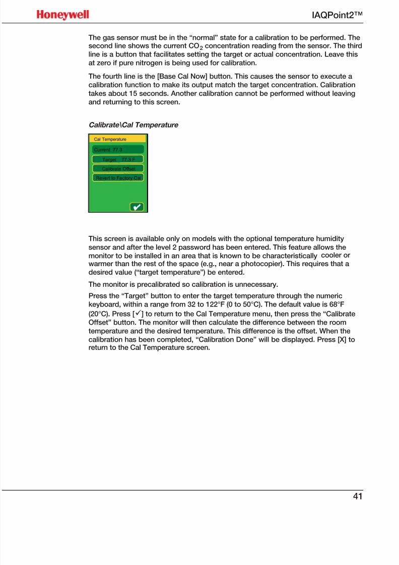
Calibrate\Cal Temperature
Cal Temperature
Current 77.3
Target 77.3 F
Calibrate Offset
Revert to Factory Cal
This screen is available only on models with the optional temperature humidity
sensor and after the level 2 password has been entered. This feature allows themonitor to be installed in an area that is known to be characteristically cooler or
warmer than the rest of the space (e.g., near a photocopier). This requires that adesired value (“target temperature”) be entered.
The monitor is precalibrated so calibration is unnecessary.
Press the “Target” button to enter the target temperature through the numerickeyboard, within a range from 32 to 122°F (0 to 50°C). The default value is 68°F
(20°C). Press [ü] to return to the Cal Temperature menu, then press the “CalibrateOffset” button. The monitor will then calculate the difference between the room
temperature and the desired temperature. This difference is the offset. When thecalibration has been completed, “Calibration Done” will be displayed. Press [X] toreturn to the Cal Temperature screen.
7/23/2019 IAQPoint2 Manual ENG Rev03
http://slidepdf.com/reader/full/iaqpoint2-manual-eng-rev03 44/8042
IAQPoint2™
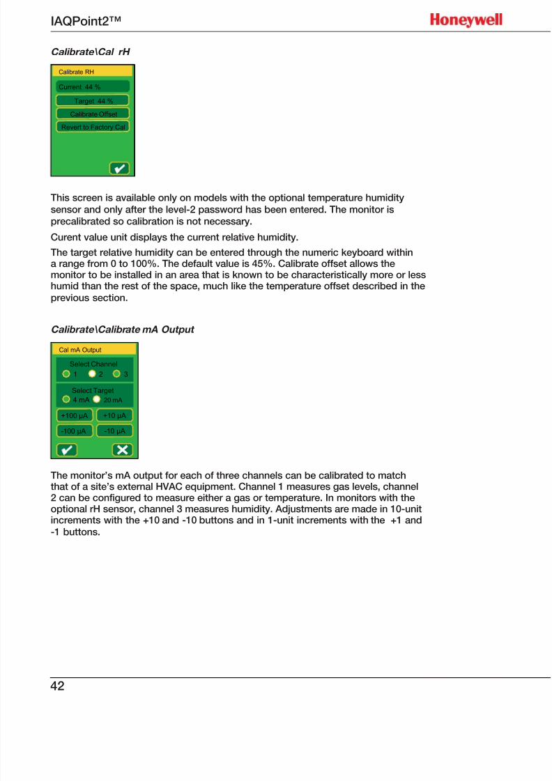
Calibrate\Cal rH
Calibrate RH
Current 44 %
Target 44 %
Calibrate Offset
Revert to Factory Cal
This screen is available only on models with the optional temperature humiditysensor and only after the level-2 password has been entered. The monitor isprecalibrated so calibration is not necessary.
Curent value unit displays the current relative humidity.
The target relative humidity can be entered through the numeric keyboard withina range from 0 to 100%. The default value is 45%. Calibrate offset allows the
monitor to be installed in an area that is known to be characteristically more or lesshumid than the rest of the space, much like the temperature offset described in theprevious section.
Calibrate\Calibrate mA Output
Cal mA Output
Select Channel
1 2 3
Select Target
4 mA 20 mA
+100 μA
-100 μA
+10 μA
-10 μA
The monitor’s mA output for each of three channels can be calibrated to matchthat of a site’s external HVAC equipment. Channel 1 measures gas levels, channel2 can be configured to measure either a gas or temperature. In monitors with theoptional rH sensor, channel 3 measures humidity. Adjustments are made in 10-unitincrements with the +10 and -10 buttons and in 1-unit increments with the +1 and-1 buttons.

7/23/2019 IAQPoint2 Manual ENG Rev03
http://slidepdf.com/reader/full/iaqpoint2-manual-eng-rev03 45/8043
IAQPoint2™
Simulate
Simulate
Normal Max Min
Gas
Temp
rH
Rly
Simulated output permits creating high or low outputs on the three sensors, allowing the operator
to verify that the system will respond as planned to changes in the gas level, temperature, orhumidity level. Any combination of minimum, maximum, or normal values of gas, temperature, andhumidty can be simulated. Default simulation selections are normal for all three parameters.
Additionally, the relay can be forced on or off from this screen. This can be useful to confirm
the operation of external equipment. For example, a service person can simulate a high CO2
concentration to confirm that an external fresh air damper moves to the full open position.
None of the monitor’s configured values is affected by changes in the Simulate menu.
Language
Language / Langage
English
Français
The IAQPoint2 monitor can be configured for English or French (Français). The default languageselection is English.
7/23/2019 IAQPoint2 Manual ENG Rev03
http://slidepdf.com/reader/full/iaqpoint2-manual-eng-rev03 46/8044
IAQPoint2™
Calibration
For the highest possible accuracy when the ABC function is off, the sensor can berecalibrated by a qualified operator. ABC cannot be disabled on a unit without adisplay.
CO2 Calibration
By default, the CO2 sensor uses an Automatic Baseline Calibration (ABC) algorithmto maintain accuracy. However, ABC is inappropriate for environments with
continuously elevated concentration and should be disabled. With ABC disabled,the CO2 sensor can be manually calibrated. The sensor’s response coefficientis fixed during manufacture. The baseline calibration affects only the offset, notthe slope of the sensor’s response. This calibration can be performed at any CO2
concentration level. However, calibration with 1,000 ppm CO2 calibration gasis simplest and is recommended. For non-ABC applications, the unit should becalibrated in the environment in which it will be used.
The calibration procedure (possible only if ABC is disabled):
1. Enter the level 2 password. By default, this is 2967.2. Navigate to Calibrate\Calibrate Gas. This screen will flash every second to
indicate calibration mode.
3. A message may be displayed indicating that ABC is enabled and calibrationis not possible. If ABC is not desired, it can be disabled in the Configure\
Configure Outputs\Auto Baseline menu.
4. Connect a cylinder of a test gas of known concentration (e.g. Honeywellpart M-501010, 1,000 ppm CO2 ) to a 0.5 lpm regulator (e.g. Honeywell part
M-502585).
5. Connect the regulator’s tube into the calibration port on the side of theIAQPoint2 monitor.
6. The top line of the display shows the mode of the CO2 sensor. Verify that this is“normal” and not some other message.
7. The second line of the display shows the current concentration. Verify that thisshows a reasonable number. Since the calibration gas flow has not yet beenstarted, this should show an ambient CO2 concentration. It is normally greaterthan 500 ppm in a room.
8. Open the regulator’s valve to start the flow of gas.
9. Wait three minutes for test gas to purge all of the ambient air out of the sensor.
10. Verify that the concentration reading stabilizes to match the cylinder CO2
concentration within ±200 ppm.11. Verify that the “Target” concentration matches the concentration of the cylinder
of test gas. If pure nitrogen is used, this should be zero. If needed, enter thecorrect concentration by pressing [Target].
12. Press [Base Cal Now].
13. The mode display should show “in base cal” for about ten seconds.
14. Verify that the mode display shows “base cal pass”.
7/23/2019 IAQPoint2 Manual ENG Rev03
http://slidepdf.com/reader/full/iaqpoint2-manual-eng-rev03 47/8045
IAQPoint2™
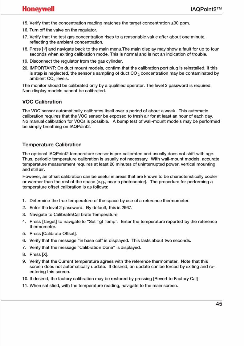
15. Verify that the concentration reading matches the target concentration ±30 ppm.
16. Turn off the valve on the regulator.
17. Verify that the test gas concentration rises to a reasonable value after about one minute,reflecting the ambient concentration.
18. Press [√] and navigate back to the main menu.The main display may show a fault for up to fourseconds when exiting calibration mode. This is normal and is not an indication of trouble.
19. Disconnect the regulator from the gas cylinder.
20. IMPORTANT: On duct mount models, confirm that the calibration port plug is reinstalled. If thisis step is neglected, the sensor’s sampling of duct CO2 concentration may be contaminated by
ambient CO2 levels.
The monitor should be calibrated only by a qualified operator. The level 2 password is required.Non-display models cannot be calibrated.
VOC Calibration
The VOC sensor automatically calibrates itself over a period of about a week. This automaticcalibration requires that the VOC sensor be exposed to fresh air for at least an hour of each day.
No manual calibration for VOCs is possible. A bump test of wall-mount models may be performedbe simply breathing on IAQPoint2.
Temperature Calibration
The optional IAQPoint2 temperature sensor is pre-calibrated and usually does not shift with age.Thus, periodic temperature calibration is usually not necessary. With wall-mount models, accuratetemperature measurement requires at least 20 minutes of uninterrupted power, vertical mounting
and still air.
However, an offset calibration can be useful in areas that are known to be characteristically cooler
or warmer than the rest of the space (e.g., near a photocopier). The procedure for performing atemperature offset calibration is as follows:
1. Determine the true temperature of the space by use of a reference thermometer.
2. Enter the level 2 password. By default, this is 2967.
3. Navigate to Calibrate\Calibrate Temperature.
4. Press [Target] to navigate to “Set Tgt Temp”. Enter the temperature reported by the referencethermometer.
5. Press [Calibrate Offset].
6. Verify that the message “in base cal” is displayed. This lasts about two seconds.7. Verify that the message “Calibration Done” is displayed.
8. Press [X].
9. Verify that the Current temperature agrees with the reference thermometer. Note that thisscreen does not automatically update. If desired, an update can be forced by exiting and re-entering this screen.
10. If desired, the factory calibration may be restored by pressing [Revert to Factory Cal]
11. When satisfied, with the temperature reading, navigate to the main screen.

7/23/2019 IAQPoint2 Manual ENG Rev03
http://slidepdf.com/reader/full/iaqpoint2-manual-eng-rev03 48/8046
IAQPoint2™
rH Calibration
The optional IAQPoint2 relative humidity sensor is pre-calibrated. However,exposure to certain chemicals may cause the reading to shift over time. Thehumidity reading can be recalibrated using the following procedure:
1. Determine the true rH level by use of a reference hygrometer.
2. Enter the level 2 password. By default, this is 2967.
3. Navigate to Calibrate\Calibrate rH.
4. Press [Target] to navigate to “Set Target rH”. Enter the relative humidityreported by the reference instrument.
5. Press [Calibrate Offset].
6. Verify that the message “in base cal” is displayed. This lasts about twoseconds.
7. Verify that the message “Calibration Done” is displayed.
8. Press [X]
9. Verify that the Current rH agrees with the reference hygrometer. Note that this
screen does not automatically update. If desired, an update can be forced byexiting and re-entering this screen.
10. If desired, the factory calibration may be restored by pressing [Revert toFactory Cal]
11. When satisfied, with the humidity reading, navigate to the main screen.
7/23/2019 IAQPoint2 Manual ENG Rev03
http://slidepdf.com/reader/full/iaqpoint2-manual-eng-rev03 49/8047
IAQPoint2™
Troubleshooting
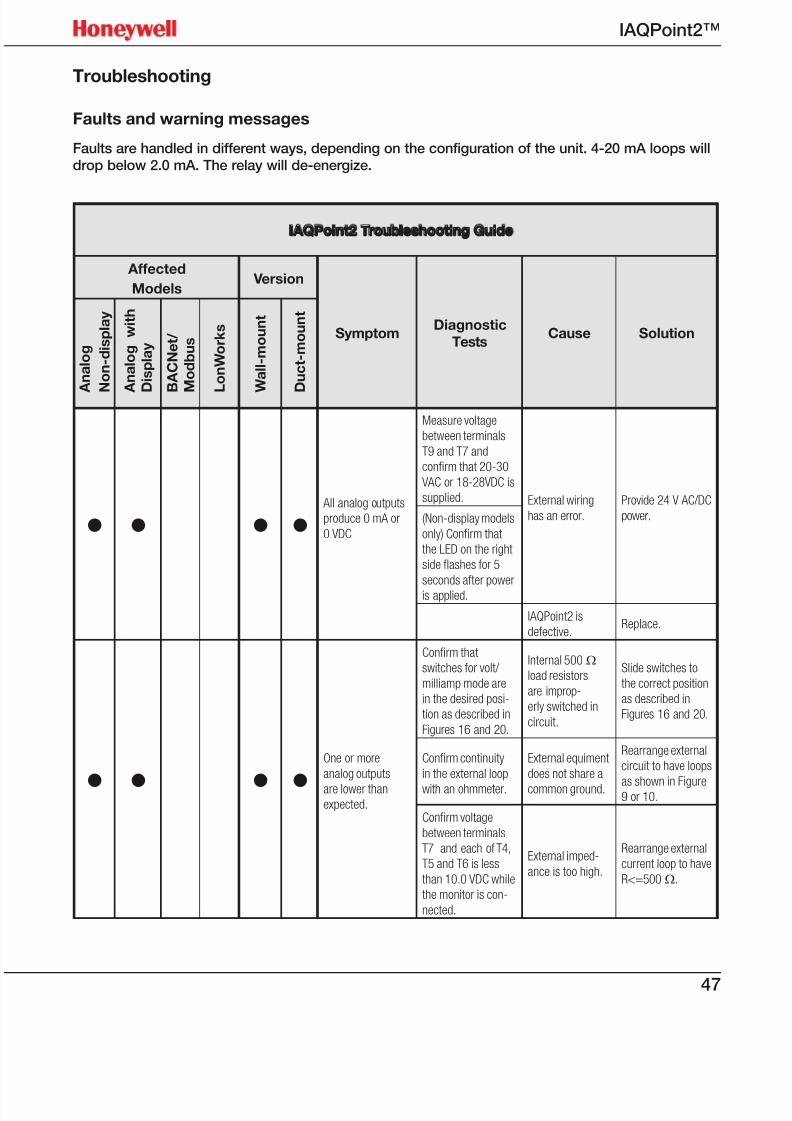
Faults and warning messages
Faults are handled in different ways, depending on the configuration of the unit. 4-20 mA loops willdrop below 2.0 mA. The relay will de-energize.
IAQPoint2 Troubleshooting Guide
Affected
Models Version
SymptomDiagnostic
TestsCause Solution
A n a l o g
N o n - d i s p l a y
A n a l o g w i t h
D i s p l a y
B A C N e t /
M o d b u s
L o n W o r k s
W a l l - m o u n t
D u c t - m o u n t
• • • • All analog outputs
produce 0 mA or
0 VDC
Measure voltage
between terminals
T9 and T7 and
confirm that 20-30
VAC or 18-28VDC is
supplied. External wiring
has an error.
Provide 24 V AC/DC
power.(Non-display models
only) Confirm that
the LED on the right
side flashes for 5
seconds after power
is applied.
IAQPoint2 is
defective.Replace.
• • • •
One or more
analog outputs
are lower thanexpected.
Confirm that
switches for volt/
milliamp mode are
in the desired posi-
tion as described in
Figures 16 and 20.
Internal 500 Ω
load resistors
are improp-
erly switched in
circuit.
Slide switches to
the correct position
as described in
Figures 16 and 20.
Confirm continuity
in the external loop
with an ohmmeter.
External equiment
does not share a
common ground.
Rearrange external
circuit to have loops
as shown in Figure9 or 10.
Confirm voltage
between terminals
T7 and each of T4,
T5 and T6 is less
than 10.0 VDC while
the monitor is con-
nected.
External imped-
ance is too high.
Rearrange external
current loop to have
R<=500 Ω.
7/23/2019 IAQPoint2 Manual ENG Rev03
http://slidepdf.com/reader/full/iaqpoint2-manual-eng-rev03 50/8048
IAQPoint2™
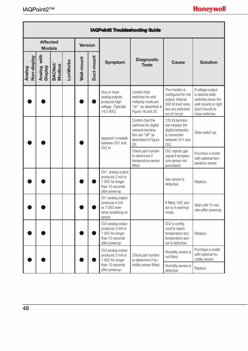
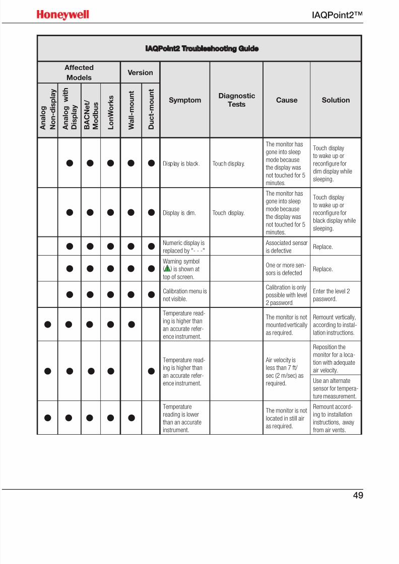
IAQPoint2 Troubleshooting Guide
Affected
Models Version
Symptom DiagnosticTests Cause Solution
A n a l o g
N o n - d i s p l a y
A n a l o g w
i t h
D i s p l a y
B A C N e t /
M o d b u s
L o n W o r k s
W a l l - m o u n t
D u c t - m o u
n t
• • • •One or more
analog outputs
produces high
voltage. (Typically
14.5 VDC)
Confirm that
switches for volt/
milliamp mode are
"on" as described in
Figure 16 and 20.
The monitor is
configured for mA
output; internal
500 Ω load resis-
tors are switched
out of circuit.
If voltage output
is desired slide
switches down (for
wall mount) or right
(duct mount) to
close switches.
• • • Apparent crosstalk
between Ch1 and
Ch2 in
Confirm that the
switches for digital
network termina-
tion are "off" as
described in Figure
20.
120 Ω termina-
tion resistor (for
digital networks)
is connected
between Ch1 and
Ch2.
Slide switch up.
Check part number
to determine if
temperature sensor
fitted.
Ch2 reports gas
signal if tempera-
ture sensor not
purchased.
Purchase a model
with optional tem-
perature sensor.
• • • •
Ch1 analog output
produces 2 mA or
1 VDC for longer
than 10 seconds
after powerup.
Gas sensor is
defective.Replace.
• • • •Ch1 analog output
produces 4 mA
or 2 VDC even
when breathing on
sensor.
If fitted, VOC sen-
sor is in warmup
mode.
Wait until 15 min-
utes after powerup.
• • • •Ch2 analog output
produces 2 mA or
1 VDC for longer
than 10 seconds
after powerup.
Ch2 is config-
ured to report
temperature and
temperature sen-
sor is defective.
Replace.
• • • •Ch3 analog output
produces 2 mA or
1 VDC for longer
than 10 seconds
after powerup.
Check part number
to determine if hu-
midity sensor fitted.
Humidity sensor is
not fitted.
Purchase a model
with optional hu-
midity sensor.
Humidity sensor is
defectiveReplace.
7/23/2019 IAQPoint2 Manual ENG Rev03
http://slidepdf.com/reader/full/iaqpoint2-manual-eng-rev03 51/8049
IAQPoint2™
IAQPoint2 Troubleshooting Guide
Affected
Models Version
Symptom DiagnosticTests Cause Solution
A n a l o g
N o n - d i s p l a y
A n a l o g w
i t h
D i s p l a y
B A C N e t /
M o d b u s
L o n W o r k s
W a l l - m o u n t
D u c t - m o u
n t
• • • • • Display is black. Touch display.
The monitor has
gone into sleep
mode because
the display was
not touched for 5
minutes.
Touch display
to wake up or
reconfigure for
dim display while
sleeping.
• • • • • Display is dim. Touch display.
The monitor has
gone into sleep
mode because
the display was
not touched for 5
minutes.
Touch displayto wake up or
reconfigure for
black display while
sleeping.
• • • • • Numeric display is
replaced by "- - -"
Associated sensor
is defectiveReplace.
• • • • •Warning symbol( ) is shown at
top of screen.
One or more sen-
sors is defectedReplace.
• • • • •Calibration menu is
not visible.
Calibration is only
possible with level2 password.
Enter the level 2
password.
• • • • •Temperature read-
ing is higher than
an accurate refer-
ence instrument.
The monitor is not
mounted vertically
as required.
Remount vertically,
according to instal-
lation instructions.
• • • • •Temperature read-
ing is higher than
an accurate refer-
ence instrument.
Air velocity is
less than 7 ft/
sec (2 m/sec) as
required.
Reposition the
monitor for a loca-
tion with adequate
air velocity.
Use an alternate
sensor for tempera-
ture measurement.
• • • • •Temperature
reading is lower
than an accurate
instrument.
The monitor is not
located in still air
as required.
Remount accord-
ing to installation
instructions, away
from air vents.

7/23/2019 IAQPoint2 Manual ENG Rev03
http://slidepdf.com/reader/full/iaqpoint2-manual-eng-rev03 52/8050
IAQPoint2™
IAQPoint2 Troubleshooting Guide
Affected
Models Version
Symptom DiagnosticTests Cause Solution
A n a l o g
N o n - d i s p l a y
A n a l o g w
i t h
D i s p l a y
B A C N e t /
M o d b u s
L o n W o r k s
W a l l - m o u n t
D u c t - m o u
n t
• • • • •
Temperature set-
point adjustment
range is restricted
to narrower than
50 - 95F (10 -
35C)
Check configura-
tion via Review\User
Config line 4.
The monitor has
been configured
for narrower tem-
perature limits
Enter level 2 pass-
word and navigate
to Configure \
Configure SetPoints
\ MaxTemp or
MinTemp.
• • • • •Features absent
from main display
screen
Navigate to Config-
ure \ Configure Dis-
play \ Main Display
Dataset. Check the
settings
The monitor is set
for simple display.
Change the settings
under Configure \
Configure Display
\ Main Display
Dataset.
Navigate to Con-
figure \ Configure
Display \ Easy Temp
Adj.
The easy tem-
perature adjust
screen is disabled
by default
Enter level 2
password and
change the setting
under Configure \
Configure Display \
Easy Temp Adj.
Check part number
to determine iftemperature and
humidity sensors are
fitted.
Some software
features are notavailable in basic
versions of the
product.
Purchase a model
with all of the
desired features
such as relay and
temperature /
humidity sensor.
• • • • • Gas reading seems
inaccurate.
Confirm that the gas
calibration port (as
shown in Figure 7) is
plugged.
The monitor is
sampling air from
outside the duct.
Plug gas calibration
port.
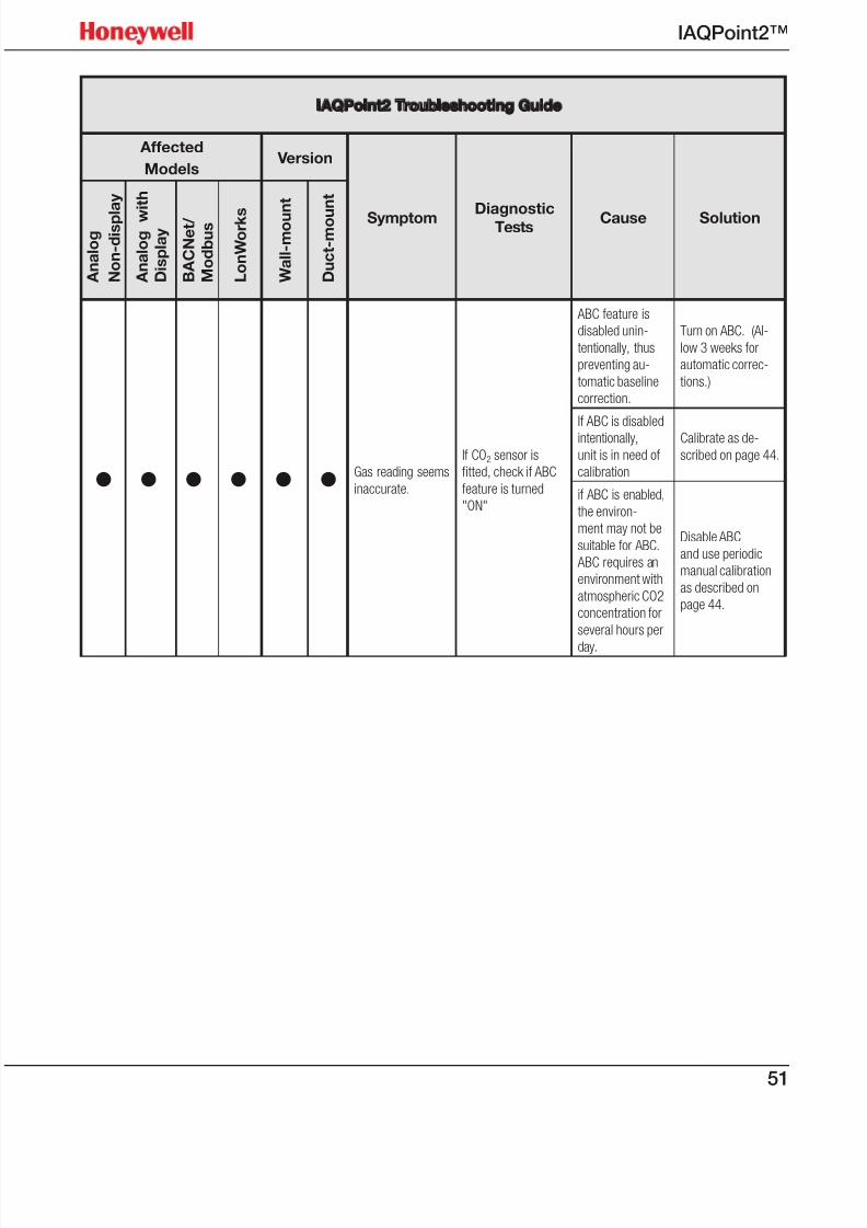
7/23/2019 IAQPoint2 Manual ENG Rev03
http://slidepdf.com/reader/full/iaqpoint2-manual-eng-rev03 53/8051
IAQPoint2™
IAQPoint2 Troubleshooting Guide
Affected
Models Version
Symptom DiagnosticTests Cause Solution
A n a l o g
N o n - d i s p l a y
A n a l o g w
i t h
D i s p l a y
B A C N e t /
M o d b u s
L o n W o r k s
W a l l - m o u n t
D u c t - m o u
n t
• • • • • • Gas reading seems
inaccurate.
If CO2 sensor is
fitted, check if ABC
feature is turned
"ON"
ABC feature is
disabled unin-
tentionally, thus
preventing au-
tomatic baseline
correction.
Turn on ABC. (Al-
low 3 weeks for
automatic correc-
tions.)
If ABC is disabled
intentionally,
unit is in need of
calibration
Calibrate as de-
scribed on page 44.
if ABC is enabled,
the environ-
ment may not be
suitable for ABC.
ABC requires an
environment with
atmospheric CO2
concentration for
several hours per
day.
Disable ABC
and use periodic
manual calibration
as described on
page 44.
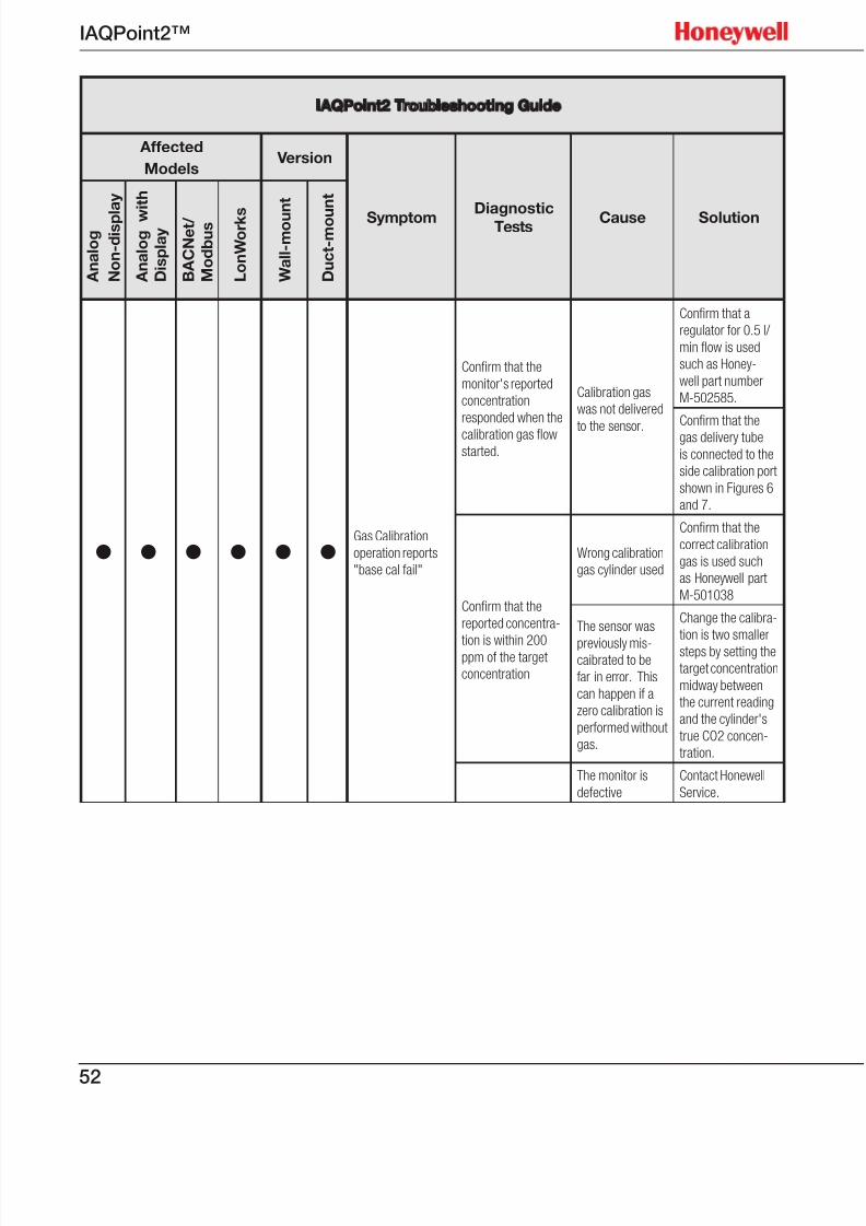
7/23/2019 IAQPoint2 Manual ENG Rev03
http://slidepdf.com/reader/full/iaqpoint2-manual-eng-rev03 54/8052
IAQPoint2™
IAQPoint2 Troubleshooting Guide
Affected
Models Version
Symptom DiagnosticTests Cause Solution
A n a l o g
N o n - d i s p l a y
A n a l o g w
i t h
D i s p l a y
B A C N e t /
M o d b u s
L o n W o r k s
W a l l - m o u n t
D u c t - m o u
n t
• • • • • •Gas Calibration
operation reports
"base cal fail"
Confirm that the
monitor's reported
concentration
responded when the
calibration gas flow
started.
Calibration gas
was not delivered
to the sensor.
Confirm that a
regulator for 0.5 l/
min flow is used
such as Honey-
well part number
M-502585.
Confirm that the
gas delivery tube
is connected to the
side calibration port
shown in Figures 6
and 7.
Confirm that the
reported concentra-
tion is within 200ppm of the target
concentration
Wrong calibration
gas cylinder used
Confirm that the
correct calibration
gas is used such
as Honeywell part
M-501038
The sensor was
previously mis-caibrated to be
far in error. This
can happen if a
zero calibration is
performed without
gas.
Change the calibra-
tion is two smaller
steps by setting the
target concentration
midway between
the current reading
and the cylinder's
true CO2 concen-
tration.
The monitor is
defective
Contact Honewell
Service.
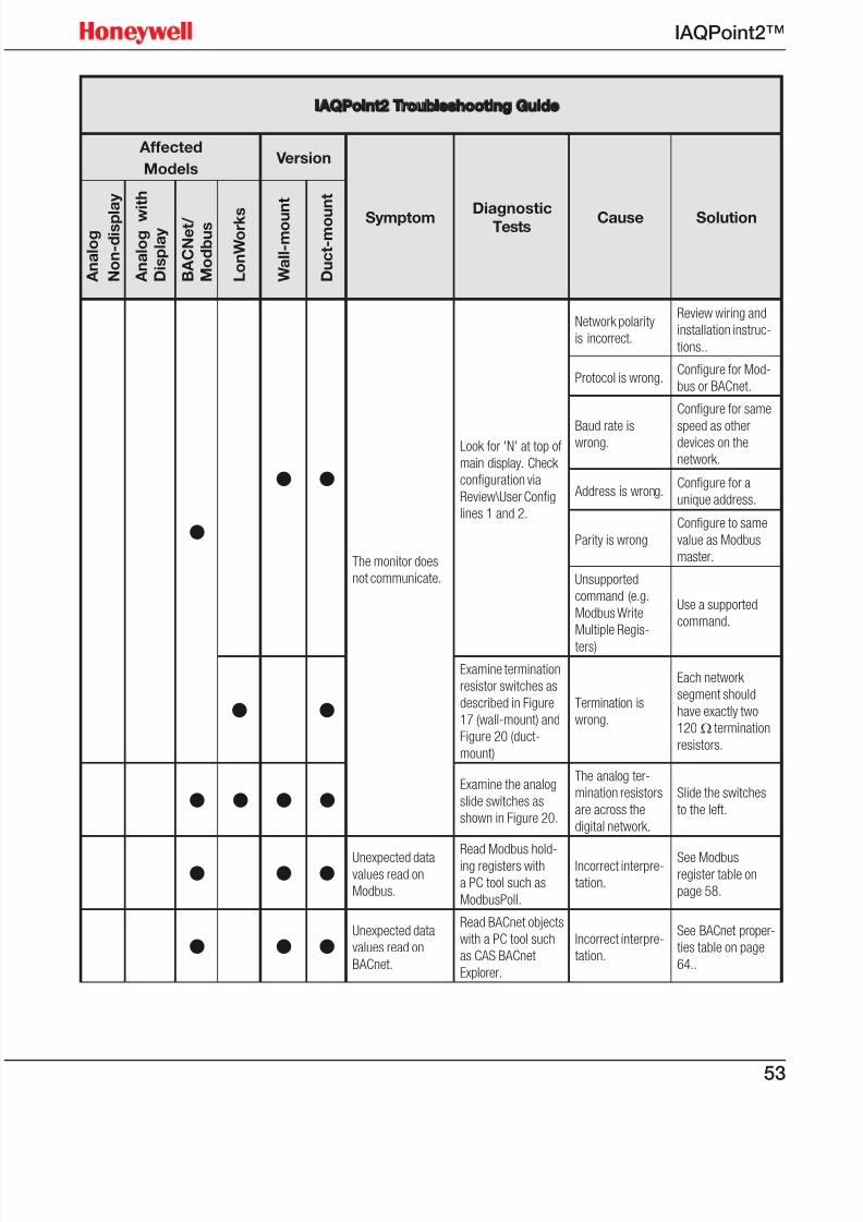
7/23/2019 IAQPoint2 Manual ENG Rev03
http://slidepdf.com/reader/full/iaqpoint2-manual-eng-rev03 55/8053
IAQPoint2™
IAQPoint2 Troubleshooting Guide
Affected
Models Version
Symptom DiagnosticTests Cause Solution
A n a l o g
N o n - d i s p l a y
A n a l o g w
i t h
D i s p l a y
B A C N e t /
M o d b u s
L o n W o r k s
W a l l - m o u n t
D u c t - m o u
n t
•
• •
The monitor does
not communicate.
Look for 'N' at top of
main display. Check
configuration via
Review\User Config
lines 1 and 2.
Network polarity
is incorrect.
Review wiring and
installation instruc-
tions..
Protocol is wrong.Configure for Mod-
bus or BACnet.
Baud rate iswrong.
Configure for same
speed as otherdevices on the
network.
Address is wrong.Configure for a
unique address.
Parity is wrong
Configure to same
value as Modbus
master.
Unsupported
command (e.g.
Modbus Write
Multiple Regis-
ters)
Use a supported
command.
• •
Examine termination
resistor switches as
described in Figure
17 (wall-mount) and
Figure 20 (duct-
mount)
Termination is
wrong.
Each network
segment should
have exactly two
120 Ω termination
resistors.
• • • •Examine the analog
slide switches as
shown in Figure 20.
The analog ter-
mination resistors
are across the
digital network.
Slide the switches
to the left.
• • •Unexpected datavalues read on
Modbus.
Read Modbus hold-
ing registers with
a PC tool such as
ModbusPoll.
Incorrect interpre-
tation.
See Modbusregister table on
page 58.
• • •Unexpected data
values read on
BACnet.
Read BACnet objects
with a PC tool such
as CAS BACnet
Explorer.
Incorrect interpre-
tation.
See BACnet proper-
ties table on page
64..
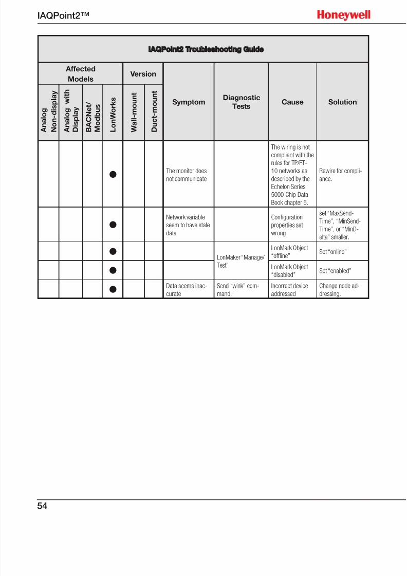
7/23/2019 IAQPoint2 Manual ENG Rev03
http://slidepdf.com/reader/full/iaqpoint2-manual-eng-rev03 56/8054
IAQPoint2™
IAQPoint2 Troubleshooting Guide
Affected
Models Version
Symptom DiagnosticTests Cause Solution
A n a l o g
N o n - d i s p l a y
A n a l o g w
i t h
D i s p l a y
B A C N e t /
M o d b u s
L o n W o r k s
W a l l - m o u n t
D u c t - m o u
n t
• The monitor does
not communicate
The wiring is not
compliant with the
rules for TP/FT-
10 networks as
described by the
Echelon Series
5000 Chip Data
Book chapter 5.
Rewire for compli-
ance.
•Network variable
seem to have stale
data
Configuration
properties set
wrong
set “MaxSend-
Time”, “MinSend-
Time”, or “MinD-
elta” smaller.
• LonMaker “Manage/
Test”
LonMark Object
“offline”Set “online”
• LonMark Object
“disabled”Set “enabled”
• Data seems inac-
curate
Send “wink” com-
mand.
Incorrect device
addressed
Change node ad-
dressing.

7/23/2019 IAQPoint2 Manual ENG Rev03
http://slidepdf.com/reader/full/iaqpoint2-manual-eng-rev03 57/8055
IAQPoint2™
Maintenance
The built-in ABC algorithm makes maintenance unnecessary in normal
environments.
Cleaning
Clean the case and the touchscreen by wiping gently with a soft cloth dampened
only with water. Do not allow water to enter the monitor’s case. Do not spray anyliquids on the touchscreen or the case. Do not use harsh or abrasive cleaningsolutions on the touchscreen or the case.
Sensor accuracy test
To test the CO2 sensor, apply 1000 ppm of CO2 test gas3. The sensor should read
±30 ppm ±5% of the test gas specification. This equates to 1000 ppm ±80 ppm ±of the test gas specification.
There is no accuracy test for VOC sensors.
Sensor poisons/inhibitors
Silicone is one of the major chemicals that has an adverse effect on VOC sensors.It forms a layer on top of the sensitive material, thus limiting the accessibility ofthe sensor surface. When this happens, sensitivity can be reduced drastically. The
effect of this on the monitor’s performance could be severe. The monitor wouldbe unable to recover from this condition. There are no poisons or inhibitors for theCO2 sensor.
VOC sensors can be affected by rapid transitions in relative humidity.
3 part no. M-501010
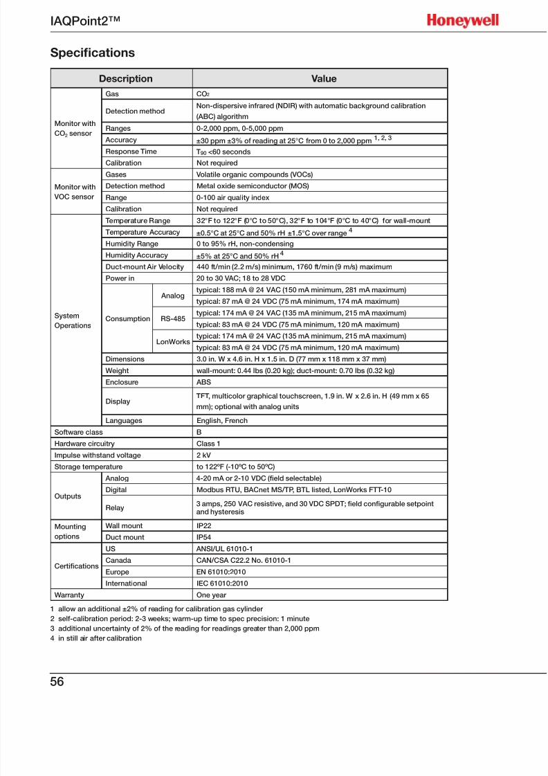
7/23/2019 IAQPoint2 Manual ENG Rev03
http://slidepdf.com/reader/full/iaqpoint2-manual-eng-rev03 58/8056
IAQPoint2™
Specications
Description Value
Monitor with
CO2 sensor
Gas CO2
Detection methodNon-dispersive infrared (NDIR) with automatic background calibration
(ABC) algorithm
Ranges 0-2,000 ppm, 0-5,000 ppm
Accuracy ±30 ppm ±3% of reading at 25°C from 0 to 2,000 ppm 1, 2, 3
Response Time T90 <60 seconds
Calibration Not required
Monitor with
VOC sensor
Gases Volatile organic compounds (VOCs)
Detection method Metal oxide semiconductor (MOS)
Range 0-100 air quality index
Calibration Not required
System
Operations
Temperature Range 32°F to 122°F (0°C to 50°C), 32°F to 104°F (0°C to 40°C) for wall-mount
Temperature Accuracy ±0.5°C at 25°C and 50% rH ±1.5°C over range 4
Humidity Range 0 to 95% rH, non-condensing
Humidity Accuracy ±5% at 25°C and 50% rH 4
Duct-mount Air Velocity 440 ft/min (2.2 m/s) minimum, 1760 ft/min (9 m/s) maximum
Power in 20 to 30 VAC; 18 to 28 VDC
Consumption
Analogtypical: 188 mA @ 24 VAC (150 mA minimum, 281 mA maximum)
typical: 87 mA @ 24 VDC (75 mA minimum, 174 mA maximum)
RS-485typical: 174 mA @ 24 VAC (135 mA minimum, 215 mA maximum)
typical: 83 mA @ 24 VDC (75 mA minimum, 120 mA maximum)
LonWorkstypical: 174 mA @ 24 VAC (135 mA minimum, 215 mA maximum)
typical: 83 mA @ 24 VDC (75 mA minimum, 120 mA maximum)
Dimensions 3.0 in. W x 4.6 in. H x 1.5 in. D (77 mm x 118 mm x 37 mm)
Weight wall-mount: 0.44 lbs (0.20 kg); duct-mount: 0.70 lbs (0.32 kg)
Enclosure ABS
DisplayTFT, multicolor graphical touchscreen, 1.9 in. W x 2.6 in. H (49 mm x 65
mm); optional with analog units
Languages English, French
Software class B
Hardware circuitry Class 1
Impulse withstand voltage 2 kV
Storage temperature to 122ºF (-10ºC to 50ºC)
Outputs
Analog 4-20 mA or 2-10 VDC (eld selectable)
Digital Modbus RTU, BACnet MS/TP, BTL listed, LonWorks FTT-10
Relay3 amps, 250 VAC resistive, and 30 VDC SPDT; eld congurable setpointand hysteresis
Mounting
options
Wall mount IP22
Duct mount IP54
Certications
US ANSI/UL 61010-1
Canada CAN/CSA C22.2 No. 61010-1
Europe EN 61010:2010
International IEC 61010:2010
Warranty One year
1 allow an additional ±2% of reading for calibration gas cylinder
2 self-calibration period: 2-3 weeks; warm-up time to spec precision: 1 minute
3 additional uncertainty of 2% of the reading for readings greater than 2,000 ppm
4 in still air after calibration

7/23/2019 IAQPoint2 Manual ENG Rev03
http://slidepdf.com/reader/full/iaqpoint2-manual-eng-rev03 59/8057
IAQPoint2™
Modbus
Data Flow
The IAQPoint2 can be configured to meet a variety of needs. There are up to three sensors, eachwith a setpoint and fault indication. With the gas sensor, a comparison is made between theconcentration and setpoint to compute a bit. A timer responds to an occupied button. There isa relay which can be made to respond to three possible inputs: the gas level, the fieldbus, or the
occupied timer. Most of the data is available over each of the three fieldbuses. This is showngraphically in Figure 28. All of the fieldbus data is colored yellow.
Screen SimulateScreen Configure /
Configure Outputs /
Set Relay
Relay
Coil
Home Screen
‘Occ’ softkey
Screen Configure / Configure
Setpoints / Set Gas Setpoint
Gas Sensor Value
Gas Sensor Fault
Gas Conc.
Fieldbus
Occ Tmr
Screen Configure / Configure
Setpoints / Set Gas Hyst
and
or
-
+
BACnet object GAS_SPT_AV
Modbus Hld Reg 40105
LonWorks nvi/oCO2SetPtPpm
Screen Configure / Configure
Output / Set Occupied Timeout
Countdown
Timerreset Q
Max (on)
Normal
Min (off)
BACnet object IAQGOOD_BI
LonWorks nvoIAQGood
BACnet object GAS_RDG_AI
Modbus Hld Reg 40102
LonWorks nvoCO2Ppm
LonWorks nvoCO2Percent
BACnet object RLY_DRV_BO
Modbus Hld Reg 40112
LonWorks nviRelayDrive
BACnet object OCC_DRV_BOModbus Hld Reg 40111
LonWorks nviDriveOccIcon
LonWorks nvisDriveOccIcon
not
BACnet object OVDTIMER_BI
Modbus Hld Reg 40101b12
LonWorks nvoOccup
LonWorks nvoSOccup
Modbus Hld Reg 40101b3
Modbus Hld Reg 40101b0, b1
LonWorks nvoCO2Fault
“Occupied”
icon
Modbus Hld Reg 40101b14
Temperature Sensor ValueBACnet object TEMP_AI
Modbus Hld Reg 40103
LonWorks nvoHVACTemp
Temperature Sensor FaultModbus Hld Reg 40101b4
LonWorks nvoTempFault
Screen Configure / Configure
Setpoints / Temp Setpoint
BACnet object Temp_SPT_AV
Modbus Hld Reg 40106
LonWorks nvi/oTempSetPt
Humidity Senso r ValueBACnet object RH_AI
Modbus Hld Reg 40104
LonWorks nvoHVACRH
Humidity Sensor FaultModbus Hld Reg 40101b8
LonWorks nvo_rH_Fault
Screen Configure / Configure
Setpoints / rH Setpoint
BACnet object Temp_SPT_AV
Modbus Hld Reg 40107
LonWorks nvi/o_rH_SetPt
Level
comparison
Figure 28. IAQPoint2 relay ow with feldbus and simulation elements
Modbus registers
Some models of the IAQPoint2 contain a digital interface for communicating over RS-485networks. This interface can be switched in software to use either the Modbus RTU or BACnetMS/TP protocols. It can communicate at any speed from 4800 to 115,200 baud. When configuredfor Modbus and 9600 baud, the IAQPoint2 is compatible with the Honeywell 301C controller. TheIAQPoint2 can directly replace an IAQPoint1 in Modbus or analog applications.
More information on Modbus can be obtained at www.modbus.org. The IAQPoint2 contains 12Modbus holding registers. hese are numbered from 40101 to 40112 – it skips over the first 100.There are no input registers, output registers, or coils. Holding registers 40101 provides a concisesummary of essential status. Two holding registers are writable via command 06.
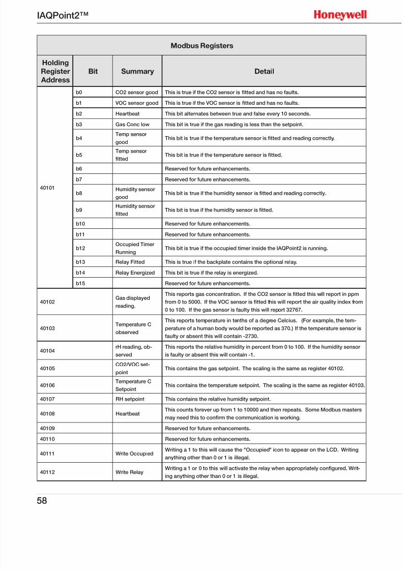
7/23/2019 IAQPoint2 Manual ENG Rev03
http://slidepdf.com/reader/full/iaqpoint2-manual-eng-rev03 60/8058
IAQPoint2™
Modbus Registers
Holding
Register
Address
Bit Summary Detail
40101
b0 CO2 sensor good This is true if the CO2 sensor is tted and has no faults.
b1 VOC sensor good This is true if the VOC sensor is tted and has no faults.
b2 Heartbeat This bit alternates between true and false every 10 seconds.
b3 Gas Conc low This bit is true if the gas reading is less than the setpoint.
b4Temp sensor
goodThis bit is true if the temperature sensor is tted and reading correctly.
b5Temp sensor
ttedThis bit is true if the temperature sensor is tted.
b6 Reserved for future enhancements.
b7 Reserved for future enhancements.
b8Humidity sensor
good
This bit is true if the humidity sensor is tted and reading correctly.
b9Humidity sensor
ttedThis bit is true if the humidity sensor is tted.
b10 Reserved for future enhancements.
b11 Reserved for future enhancements.
b12Occupied Timer
RunningThis bit is true if the occupied timer inside the IAQPoint2 is running.
b13 Relay Fitted This is true if the backplate contains the optional relay.
b14 Relay Energized This bit is true if the relay is energized.
b15 Reserved for future enhancements.
40102 Gas displayedreading.
This reports gas concentration. If the CO2 sensor is tted this will report in ppm
from 0 to 5000. If the VOC sensor is tted this will report the air quality index from
0 to 100. If the gas sensor is faulty this will report 32767.
40103Temperature C
observed
This reports temperature in tenths of a degree Celcius. (For example, the tem-
perature of a human body would be reported as 370.) If the temperature sensor is
faulty or absent this will contain -2730.
40104rH reading, ob-
served
This reports the relative humidity in percent from 0 to 100. If the humidity sensor
is faulty or absent this will contain -1.
40105CO2/VOC set-
pointThis contains the gas setpoint. The scaling is the same as register 40102.
40106Temperature C
SetpointThis contains the temperature setpoint. The scaling is the same as register 40103.
40107 RH setpoint This contains the relative humidity setpoint.
40108 HeartbeatThis counts forever up from 1 to 10000 and then repeats. Some Modbus masters
may need this to conrm the communication is working.
40109 Reserved for future enhancements.
40110 Reserved for future enhancements.
40111 Write OccupiedWriting a 1 to this will cause the "Occupied" icon to appear on the LCD. Writing
anything other than 0 or 1 is illegal.
40112 Write RelayWriting a 1 or 0 to this will activate the relay when appropriately congured. Writ-
ing anything other than 0 or 1 is illegal.

7/23/2019 IAQPoint2 Manual ENG Rev03
http://slidepdf.com/reader/full/iaqpoint2-manual-eng-rev03 61/8059
IAQPoint2™
BACnet
Introduction
When configured for BACnet, the IAQPoint2 contains ten BACnet objects. The reading from eachof the three sensors is conveyed by a analog input objects while the setpoints are conveyed byan analog value objects. Additionally, two binary inputs provide a simple indication of relative air
quality and the occupied timer status. Finally, two binary outputs facilitate manipulation of therelay and the occupied icon by BACnet. Each object has several properties which can be read andsometimes written. All of the objects and properties of the IAQPoint2 BACnet device are listed inthe table at the end of this section. A BACnet protocol implementation conformance statement
(PICS) is included in this section, as well. More information about BACnet can be found at www.
bacnet.org.
ANNEX A - PROTOCOL IMPLEMENTATION CONFORMANCE STATEMENT
(NORMATIVE)
(This annex is part of this Standard and is required for its use.)
BACnet Protocol Implementation Conformance Statement
Date: 2012 Dec 12
Vendor Name: Honeywell International Inc
Product Name: IAQPoint2
Product Model Number: Sixteen variations of the product are offered:
IAQ-WNC-D, IAQ-WNC-R-D, IAQ-WNC-TRH-D, IAQ-WNC-TRH-R-D,
IAQ-WNV-D, IAQ-WNV-R-D, IAQ-WNV-TRH-D, IAQ-WNV-TRH-R-D,
IAQ-DNC-D, IAQ-DNC-R-D, IAQ-DNC-TRH-D IAQ-DNC-TRH-R-D,IAQ-DNV-D, IAQ-DNV-R-D, IAQ-DNV-TRH-D, IAQ-DNV-TRH-R-D
Application Software Version: v1.05b4 Firmware Revision: v1.05b4
BACnet Protocol Revision: 7
Product Description: The IAQPoint2 smart sensor measures three indoor air quality parameters:
carbon dioxide or volatile organic compounds, plus temperature and humidity. Both wall mountand duct mount versions are available with a customizable touchscreen. The IAQPoint2 facilitatesenergy efficiency, productivity, health and comfort by facilitating demand controlled ventilation.
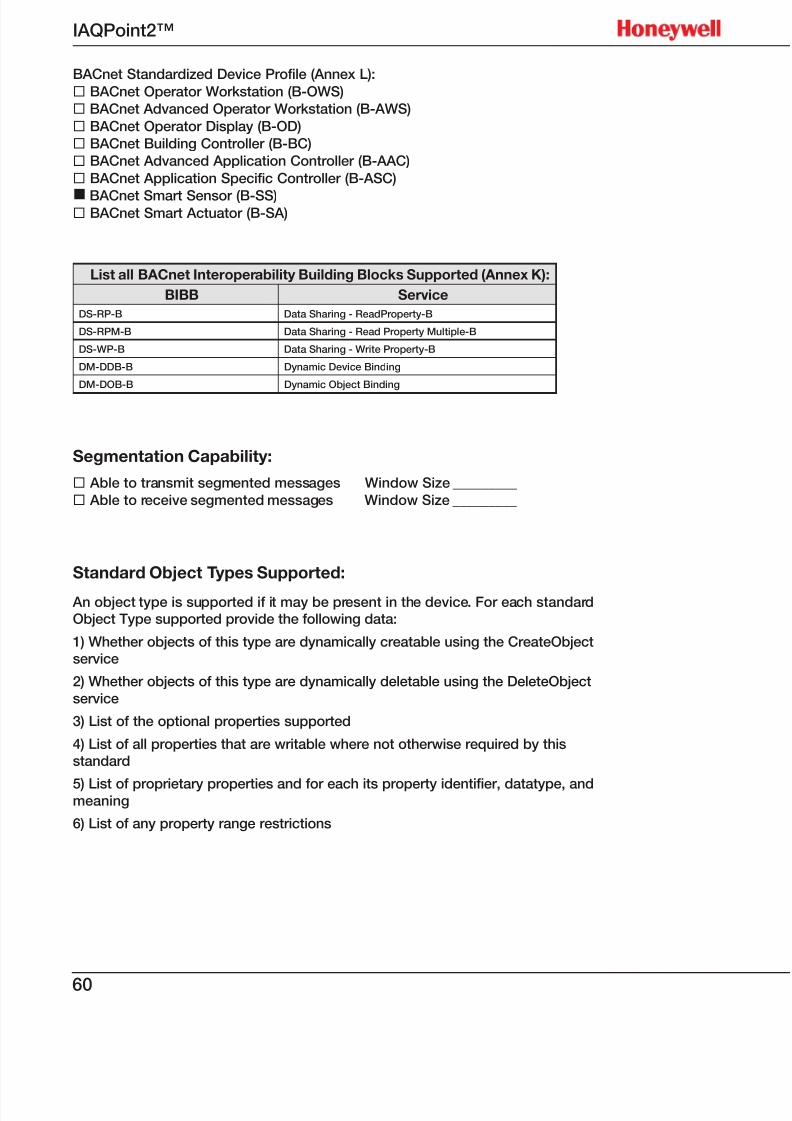
7/23/2019 IAQPoint2 Manual ENG Rev03
http://slidepdf.com/reader/full/iaqpoint2-manual-eng-rev03 62/8060
IAQPoint2™
BACnet Standardized Device Profile (Annex L):
¨ BACnet Operator Workstation (B-OWS)
¨ BACnet Advanced Operator Workstation (B-AWS)
¨ BACnet Operator Display (B-OD)
¨ BACnet Building Controller (B-BC)
¨ BACnet Advanced Application Controller (B-AAC)
¨ BACnet Application Specific Controller (B-ASC)
n BACnet Smart Sensor (B-SS)¨ BACnet Smart Actuator (B-SA)
List all BACnet Interoperability Building Blocks Supported (Annex K):
BIBB Service
DS-RP-B Data Sharing - ReadProperty-B
DS-RPM-B Data Sharing - Read Property Multiple-B
DS-WP-B Data Sharing - Write Property-B
DM-DDB-B Dynamic Device Binding
DM-DOB-B Dynamic Object Binding
Segmentation Capability:
¨ Able to transmit segmented messages Window Size _________
¨ Able to receive segmented messages Window Size _________
Standard Object Types Supported:
An object type is supported if it may be present in the device. For each standardObject Type supported provide the following data:
1) Whether objects of this type are dynamically creatable using the CreateObjectservice
2) Whether objects of this type are dynamically deletable using the DeleteObject
service
3) List of the optional properties supported
4) List of all properties that are writable where not otherwise required by thisstandard
5) List of proprietary properties and for each its property identifier, datatype, andmeaning
6) List of any property range restrictions
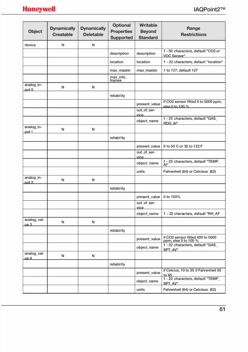
7/23/2019 IAQPoint2 Manual ENG Rev03
http://slidepdf.com/reader/full/iaqpoint2-manual-eng-rev03 63/8061
IAQPoint2™
ObjectDynamically
Creatable
Dynamically
Deletable
Optional
Properties
Supported
Writable
Beyond
Standard
Range
Restrictions
device N N
description description1 - 50 characters, default "CO2 or
VOC Sensor"
location location 1 - 22 characters, default "location"
max_master max_master 1 to 127, default 127
max_info_frames
analog_in-
put 0N N
reliability
present_valueif CO2 sensor tted 0 to 5000 ppm,
else 0 to 100 %out_of_ser-
vice
object_name1 - 22 characters, default "GAS_
RDG_AI"analog_in-
put 1N N
reliability
present_value 0 to 50 C or 32 to 122 F
out_of_ser-
vice
object_name 1 - 22 characters, default "TEMP_ AI"
units Fahrenheit (64) or Celcisus (62)
analog_in-
put 2N N
reliability
present_value 0 to 100%
out_of_ser-
vice
object_name 1 - 22 characters, default "RH_AI"
analog_val-
ue 3N N
reliability
present_value if CO2 sensor tted 400 to 5000ppm, else 0 to 100 %
object_name 1 - 22 characters, default "GAS_SPT_AV"analog_val-
ue 4N N
reliability
present_valueif Celcius, 10 to 35 if Fahrenheit 50
to 95
object_name1 - 22 characters, default "TEMP_
SPT_AV"
units Fahrenheit (64) or Celcisus (62)
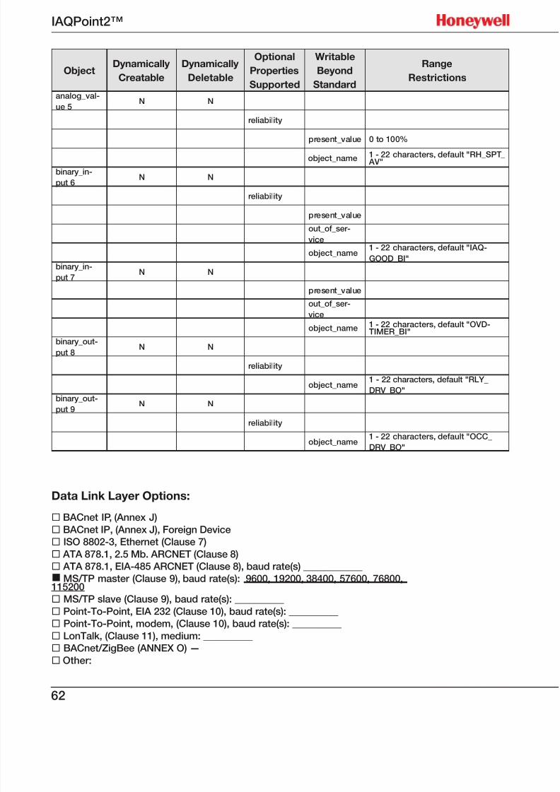
7/23/2019 IAQPoint2 Manual ENG Rev03
http://slidepdf.com/reader/full/iaqpoint2-manual-eng-rev03 64/8062
IAQPoint2™
ObjectDynamically
Creatable
Dynamically
Deletable
Optional
Properties
Supported
Writable
Beyond
Standard
Range
Restrictions
analog_val-
ue 5N N
reliability
present_value 0 to 100%
object_name 1 - 22 characters, default "RH_SPT_ AV"
binary_in-
put 6N N
reliability
present_value
out_of_ser-
vice
object_name1 - 22 characters, default "IAQ-
GOOD_BI"binary_in-
put 7N N
present_value
out_of_ser-
vice
object_name 1 - 22 characters, default "OVD-TIMER_BI"
binary_out-
put 8N N
reliability
object_name1 - 22 characters, default "RLY_
DRV_BO"binary_out-
put 9N N
reliability
object_name1 - 22 characters, default "OCC_
DRV_BO"
Data Link Layer Options:
¨ BACnet IP, (Annex J)
¨ BACnet IP, (Annex J), Foreign Device
¨ ISO 8802-3, Ethernet (Clause 7)
¨ ATA 878.1, 2.5 Mb. ARCNET (Clause 8)¨ ATA 878.1, EIA-485 ARCNET (Clause 8), baud rate(s) ____________
n MS/TP master (Clause 9), baud rate(s): 9600, 19200, 38400, 57600, 76800,115200
¨ MS/TP slave (Clause 9), baud rate(s): __________
¨ Point-To-Point, EIA 232 (Clause 10), baud rate(s): __________
¨ Point-To-Point, modem, (Clause 10), baud rate(s): __________
¨ LonTalk, (Clause 11), medium: __________
¨ BACnet/ZigBee (ANNEX O) —
¨ Other:
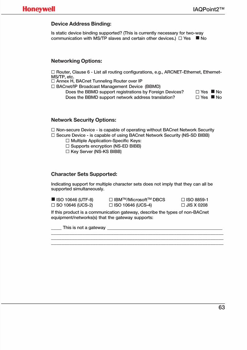
7/23/2019 IAQPoint2 Manual ENG Rev03
http://slidepdf.com/reader/full/iaqpoint2-manual-eng-rev03 65/8063
IAQPoint2™
Device Address Binding:
Is static device binding supported? (This is currently necessary for two-way
communication with MS/TP slaves and certain other devices.) ¨ Yes n No
Networking Options:
¨ Router, Clause 6 - List all routing configurations, e.g., ARCNET-Ethernet, Ethernet-MS/TP, etc.¨ Annex H, BACnet Tunneling Router over IP
¨ BACnet/IP Broadcast Management Device (BBMD)
Does the BBMD support registrations by Foreign Devices? ¨ Yes n No
Does the BBMD support network address translation? ¨ Yes n No
Network Security Options:¨ Non-secure Device - is capable of operating without BACnet Network Security
¨ Secure Device - is capable of using BACnet Network Security (NS-SD BIBB)
¨ Multiple Application-Specific Keys:
¨ Supports encryption (NS-ED BIBB)
¨ Key Server (NS-KS BIBB)
Character Sets Supported:
Indicating support for multiple character sets does not imply that they can all besupported simultaneously.
n ISO 10646 (UTF-8) ¨ IBMTM /MicrosoftTM DBCS ¨ ISO 8859-1
¨ SO 10646 (UCS-2) ¨ ISO 10646 (UCS-4) ¨ JIS X 0208
If this product is a communication gateway, describe the types of non-BACnetequipment/networks(s) that the gateway supports:
____ This is not a gateway ___________________________________________________________________________________________________________________________________________________________________________________________________________________________________________________
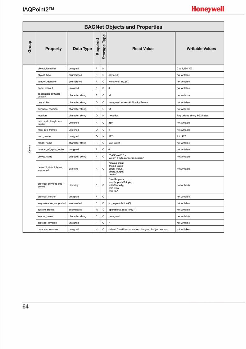
7/23/2019 IAQPoint2 Manual ENG Rev03
http://slidepdf.com/reader/full/iaqpoint2-manual-eng-rev03 66/8064
IAQPoint2™
BACNet Objects and Properties
G r o u p
Property Data Type
R e q u i r e d
S t o r a g e T y p e
Read Value Writable Values
D e v i c e
object_identier unsigned R N 1 0 to 4,194,302
object_type enumerated R C device (8) not writable
vendor_identier enumerated R C Honeywell Inc. (17) not writable
apdu_timeout unsigned R C 0 not writable
application_software_version
character string R C v1 not writable
description character string O C Honeywell Indoor Air Quality Sensor not writable
rmware_revision character string R C v1 not writable
location character string O N "location" Any unique string 1-22 bytes
max_apdu_length_ac-cepted unsigned R C 480 not writable
max_info_frames unsigned O C 1 not writable
max_master unsigned O N 127 1 to 127
model_name character string R C IAQPoint2 not writable
number_of_apdu_retries unsigned R C 0 not writable
object_name character string R C“"IAQPoint2_” +lower 12 bytes of serial number"
not writable
protocol_object_types_supported
bit string R C
"analog_input,analog_value,binary_input,binary_output,device"
not writable
protocol_services_sup-ported
bit string R C
"readProperty,
readPropertyMultiple,writeProperty,who_Has,
who_Is,"
not writable
protocol_version unsigned R C 1 not writable
segmentation_supported enumerated R C no_segmentation (3) not writable
system_status enumerated R C operational_read_only (1) not writable
vendor_name character string R C Honeywell not writable
protocol_revision unsigned R C 7 not writable
database_revision unsigned N C default 0 - will increment on changes of object names not writable
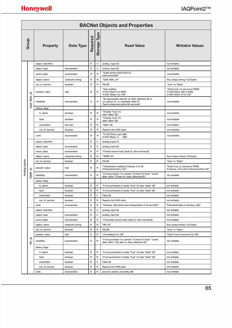
7/23/2019 IAQPoint2 Manual ENG Rev03
http://slidepdf.com/reader/full/iaqpoint2-manual-eng-rev03 67/8065
IAQPoint2™
BACNet Objects and Properties
G r o u p
Property Data Type
R e q u i r e d
S t o r a g e T y p e
Read Value Writable Values
A n a
l o g I n p u t s
G A S_
R D G_
A I
object_identier R C analog_input (0) not writable
object_type enumerated R C analog_input (0) not writable
event_state enumerated R R"if gas sensor fault Fault (1),else normal (0)"
not writable
object_name character string R N "GAS_RDG_AI" Any unique string 1-22 bytes
out_of_service boolean R R FALSE "true" or "false"
present_value real R R"Gas readingif CO2 tted, 0 to 5000 if VOC tted, 0 to 100"
"Only if out_of_service is TRUE.If CO2 tted, 400 to 5000 if VOC tted, 10 to 100"
reliability enumerated O R"As appropriate reports no_fault_detected (0) orno_sensor (1) or unreliable other (7)Fault is detected within 60 seconds"
not writable
status_ags
in_alarm boolean R R"if faulty “true” (1)
else “false” (0)"
not writable
fault boolean R R"if faulty “true” (1)else “false” (0)"
not writable
overridden boolean R R "false" (0) not writable
out_of_service boolean R R Reports the OOS state not writable
units enumerated R N"if CO2 tted, ppm (96) if VOC tted, % (98)"
not writable
T E M P
_ A I
object_identier R C analog_input (1)
object_type enumerated R C analog_input (0)
event_state enumerated R R "if temp sensor fault, fault (1), else normal (0)"
object_name character string R N "TEMP_AI" Any unique string 1-22 bytes
out_of_service boolean R R FALSE "true" or "false"
present_value real R R"Temperature reading if Celcius, 0 to 50if Fahrenheit 32 to 122"
"Only if out_of_service is TRUEif Celcius, 10 to 35 if Fahrenheit 50 to 95"
reliability enumerated O R"if not purchase “no_sensor” (1) else if in fault “unreli-able_other” (7) else no_fault_detected (0)"
not writable
status_ags
in_alarm boolean R R "if not purchased or faulty “true” (1) else “false” (0)" not writable
fault boolean R R "if not purchased or faulty “true” (1) else “false” (0)" not writable
overridden boolean R C False (0) not writable
out_of_service boolean R R Reports the OOS state not writable
units enumerated R N "Celcisus (62) (Units here independent of UI and AV4)" "Fahrenheit (64) or Celcisus (62)"
R H_
A I
object_identier R C analog_input (2) not writable
object_type enumerated R C analog_input (0) not writable
event_state enumerated R R "if humidity sensor fault, fault (1), else normal (0)" not writable
object_name character string R N "RH_AI" Any unique string 1-22 bytes
out_of_service boolean R R FALSE "true" or "false"
present_value real R R "rH reading 0 to 100" "Only if out of service 0 to 100"
reliability enumerated O R"if not purchase “no_sensor” (1) else if in fault “unreli-able_other” (10) else no_fault_detected (0)"
not writable
status_ags
in_alarm boolean R R "if not purchased or faulty “true” (1) else “false” (0)" not writable
fault boolean R R "if not purchased or faulty “true” (1) else “false” (0)" not writable
overridden boolean R C False (0) not writable
out_of_service boolean R R Reports the OOS state not writable
units enumerated R N percent_relative_humidity (29) not writable
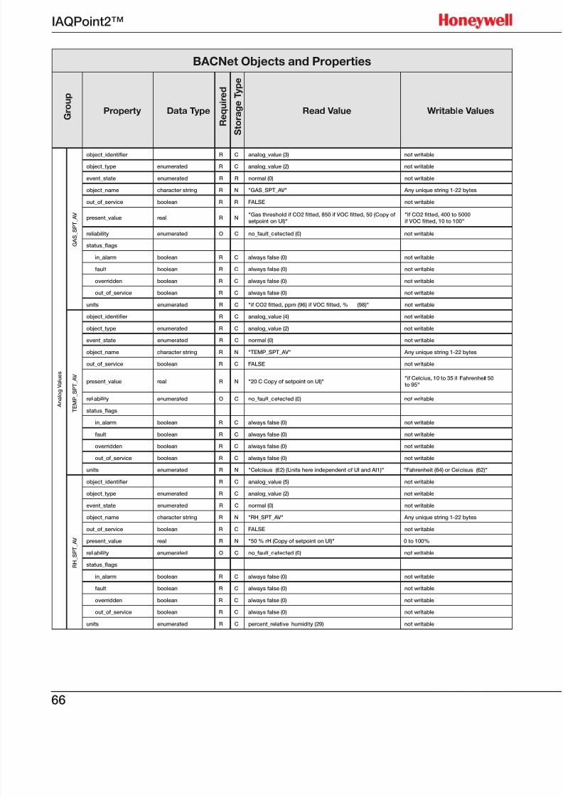
7/23/2019 IAQPoint2 Manual ENG Rev03
http://slidepdf.com/reader/full/iaqpoint2-manual-eng-rev03 68/8066
IAQPoint2™
BACNet Objects and Properties
G r o u p
Property Data Type
R e q u i r e d
S t o r a g e T y p e
Read Value Writable Values
A n a l o g V a l u e s
G A S_
S P T_
A V
object_identier R C analog_value (3) not writable
object_type enumerated R C analog_value (2) not writable
event_state enumerated R R normal (0) not writable
object_name character string R N "GAS_SPT_AV" Any unique string 1-22 bytes
out_of_service boolean R R FALSE not writable
present_value real R N"Gas threshold if CO2 tted, 850 if VOC tted, 50 (Copy of
setpoint on UI)""If CO2 tted, 400 to 5000 if VOC tted, 10 to 100"
reliability enumerated O C no_fault_detected (0) not writable
status_ags
in_alarm boolean R C always false (0) not writable
fault boolean R C always false (0) not writable
overridden boolean R C always false (0) not writable
out_of_service boolean R C always false (0) not writable
units enumerated R C "if CO2 tted, ppm (96) if VOC tted, % (98)" not writable
T E M P_
S P T_
A V
object_identier R C analog_value (4) not writable
object_type enumerated R C analog_value (2) not writable
event_state enumerated R C normal (0) not writable
object_name character string R N "TEMP_SPT_AV" Any unique string 1-22 bytes
out_of_service boolean R C FALSE not writable
present_value real R N "20 C Copy of setpoint on UI)""if Celcius, 10 to 35 if Fahrenheit 50to 95"
reliability enumerated O C no_fault_detected (0) not writable
status_ags
in_alarm boolean R C always false (0) not writable
fault boolean R C always false (0) not writable
overridden boolean R C always false (0) not writable
out_of_service boolean R C always false (0) not writable
units enumerated R N "Celcisus (62) (Units here independent of UI and AI1)" "Fahrenheit (64) or Celcisus (62)"
R H_ S P T_
A V
object_identier R C analog_value (5) not writable
object_type enumerated R C analog_value (2) not writable
event_state enumerated R C normal (0) not writable
object_name character string R N "RH_SPT_AV" Any unique string 1-22 bytes
out_of_service boolean R C FALSE not writable
present_value real R N "50 % rH (Copy of setpoint on UI)" 0 to 100%
reliability enumerated O C no_fault_detected (0) not writable
status_ags
in_alarm boolean R C always false (0) not writable
fault boolean R C always false (0) not writable
overridden boolean R C always false (0) not writable
out_of_service boolean R C always false (0) not writable
units enumerated R C percent_relative_humidity (29) not writable
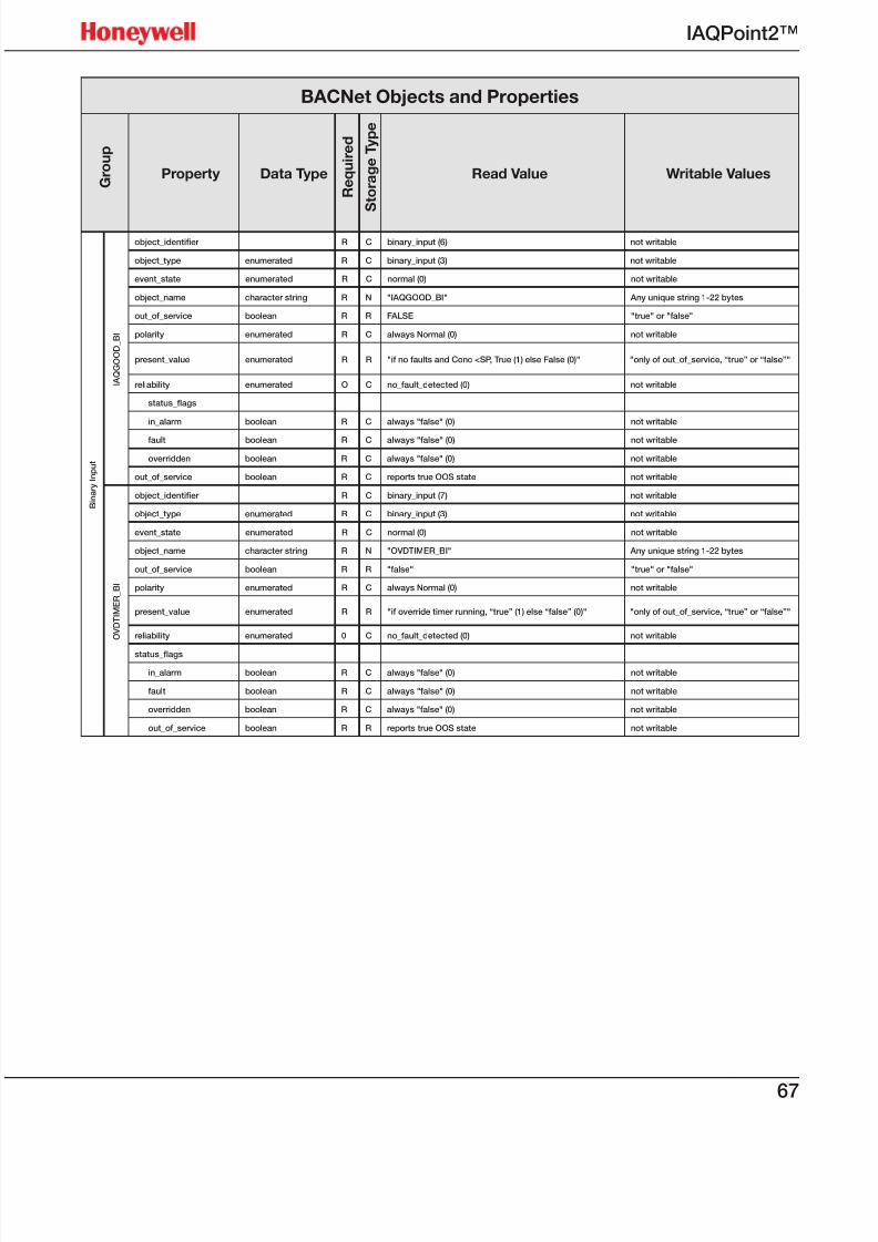
7/23/2019 IAQPoint2 Manual ENG Rev03
http://slidepdf.com/reader/full/iaqpoint2-manual-eng-rev03 69/8067
IAQPoint2™
BACNet Objects and Properties
G r o u p
Property Data Type
R e q u i r e d
S t o r a g e T y p e
Read Value Writable Values
B i n a r y I n p u t
I A Q G O O D_
B I
object_identier R C binary_input (6) not writable
object_type enumerated R C binary_input (3) not writable
event_state enumerated R C normal (0) not writable
object_name character string R N "IAQGOOD_BI" Any unique string 1-22 bytes
out_of_service boolean R R FALSE "true" or "false"
polarity enumerated R C always Normal (0) not writable
present_value enumerated R R "if no faults and Conc <SP, True (1) else False (0)" "only of out_of_service, “true” or “false”"
reliability enumerated O C no_fault_detected (0) not writable
status_ags
in_alarm boolean R C always "false" (0) not writable
fault boolean R C always "false" (0) not writable
overridden boolean R C always "false" (0) not writable
out_of_service boolean R C reports true OOS state not writable
O V D T I M E R_
B I
object_identier R C binary_input (7) not writable
object_type enumerated R C binary_input (3) not writable
event_state enumerated R C normal (0) not writable
object_name character string R N "OVDTIMER_BI" Any unique string 1-22 bytes
out_of_service boolean R R "false" "true" or "false"
polarity enumerated R C always Normal (0) not writable
present_value enumerated R R "if override timer running, “true” (1) else “false” (0)" "only of out_of_service, “true” or “false”"
reliability enumerated 0 C no_fault_detected (0) not writable
status_ags
in_alarm boolean R C always "false" (0) not writable
fault boolean R C always "false" (0) not writable
overridden boolean R C always "false" (0) not writable
out_of_service boolean R R reports true OOS state not writable
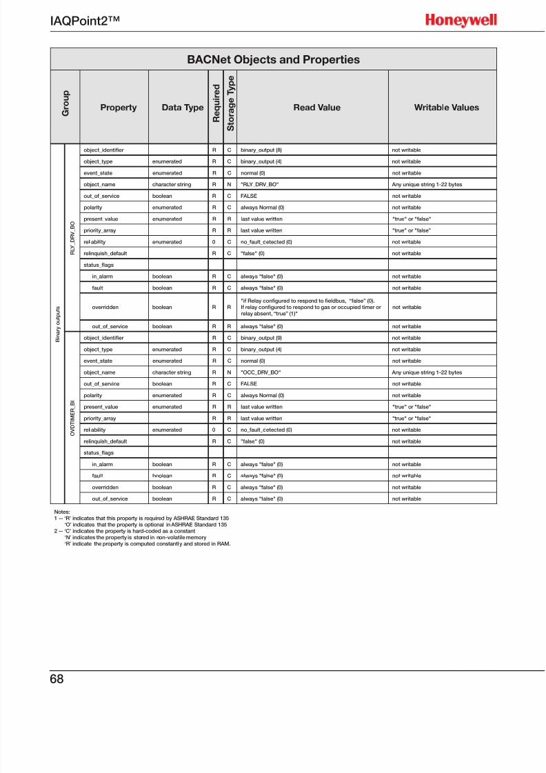
7/23/2019 IAQPoint2 Manual ENG Rev03
http://slidepdf.com/reader/full/iaqpoint2-manual-eng-rev03 70/8068
IAQPoint2™
BACNet Objects and Properties
G r o u p
Property Data Type
R e q u i r e d
S t o r a g e T y p e
Read Value Writable Values
B i n a r y o u t p u t s
R L Y_
D R V_
B O
object_identier R C binary_output (8) not writable
object_type enumerated R C binary_output (4) not writable
event_state enumerated R C normal (0) not writable
object_name character string R N "RLY_DRV_BO" Any unique string 1-22 bytes
out_of_service boolean R C FALSE not writable
polarity enumerated R C always Normal (0) not writable
present_value enumerated R R last value written "true" or "false"
priority_array R R last value written "true" or "false"
reliability enumerated 0 C no_fault_detected (0) not writable
relinquish_default R C "false" (0) not writable
status_ags
in_alarm boolean R C always "false" (0) not writable
fault boolean R C always "false" (0) not writable
overridden boolean R R"if Relay congured to respond to eldbus, “false” (0). If relay congured to respond to gas or occupied timer or
relay absent, “true” (1)"not writable
out_of_service boolean R R always "false" (0) not writable
O V D T I M E R_ B I
object_identier R C binary_output (9) not writable
object_type enumerated R C binary_output (4) not writable
event_state enumerated R C normal (0) not writable
object_name character string R N "OCC_DRV_BO" Any unique string 1-22 bytes
out_of_service boolean R C FALSE not writable
polarity enumerated R C always Normal (0) not writable
present_value enumerated R R last value written "true" or "false"
priority_array R R last value written "true" or "false"
reliability enumerated 0 C no_fault_detected (0) not writable
relinquish_default R C "false" (0) not writable
status_ags
in_alarm boolean R C always "false" (0) not writable
fault boolean R C always "false" (0) not writable
overridden boolean R C always "false" (0) not writable
out_of_service boolean R C always "false" (0) not writable
Notes:1 -- ‘R’ indicates that this property is required by ASHRAE Standard 135 ‘O’ indicates that the property is optional in ASHRAE Standard 1352 -- ‘C’ indicates the property is hard-coded as a constant ‘N’ indicates the property is stored in non-volatile memory
‘R’ indicate the property is computed constantly and stored in RAM.
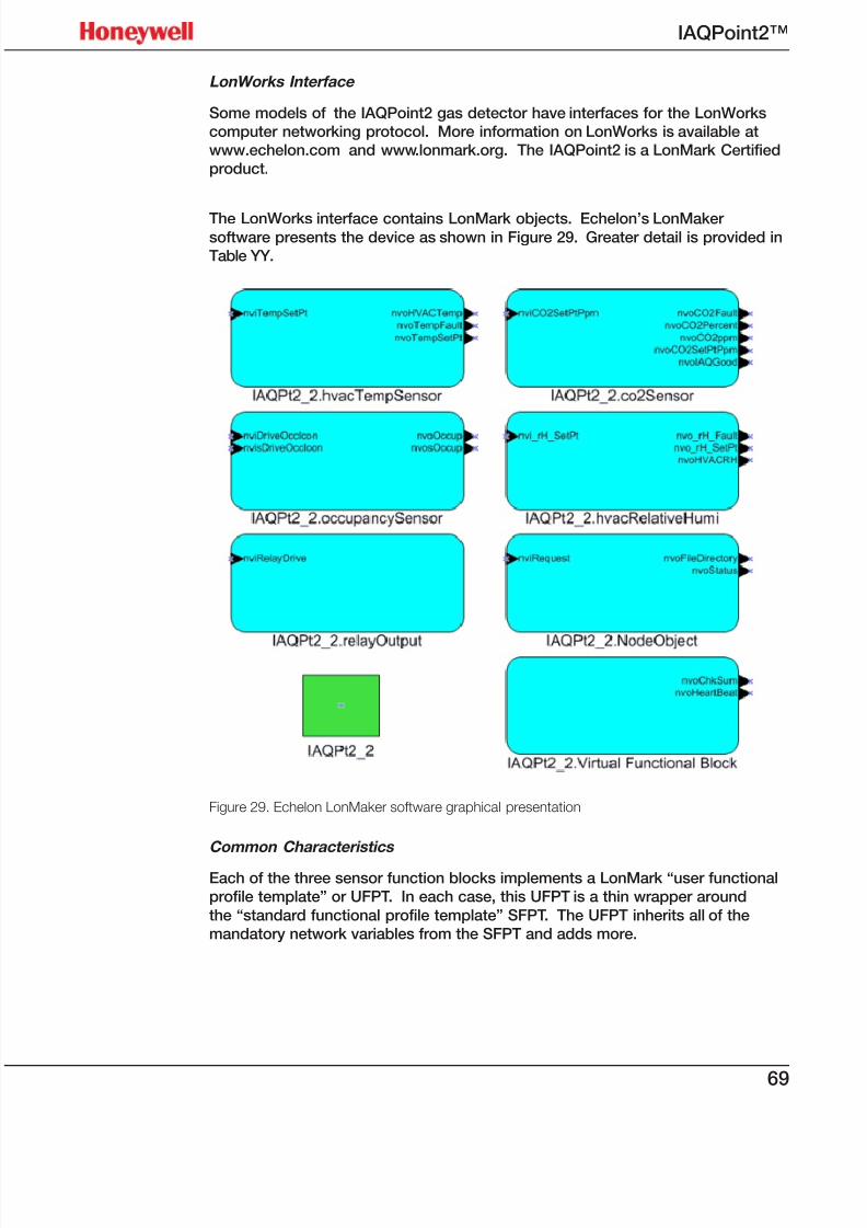
7/23/2019 IAQPoint2 Manual ENG Rev03
http://slidepdf.com/reader/full/iaqpoint2-manual-eng-rev03 71/8069
IAQPoint2™
LonWorks Interface
Some models of the IAQPoint2 gas detector have interfaces for the LonWorkscomputer networking protocol. More information on LonWorks is available atwww.echelon.com and www.lonmark.org. The IAQPoint2 is a LonMark Certifiedproduct.
The LonWorks interface contains LonMark objects. Echelon’s LonMakersoftware presents the device as shown in Figure 29. Greater detail is provided inTable YY.
Figure 29. Echelon LonMaker software graphical presentation
Common Characteristics
Each of the three sensor function blocks implements a LonMark “user functionalprofile template” or UFPT. In each case, this UFPT is a thin wrapper around
the “standard functional profile template” SFPT. The UFPT inherits all of themandatory network variables from the SFPT and adds more.
7/23/2019 IAQPoint2 Manual ENG Rev03
http://slidepdf.com/reader/full/iaqpoint2-manual-eng-rev03 72/8070
IAQPoint2™
The LonWorks interface has seven network variables of type SNVT_switch. Theseare each used simply as a bit. Thus the only output values that will ever be
produced are a LonMark “on” or “off”, which are (100.0; 1) and (0.0; 0) respectively.Similarly, the only input values that will be accepted are “on” and “off”. Othervalues will be ignored.
Each of the three sensor functional blocks has a network variable output for faultsof type SNVT_switch. This will hold the value “off” if the IAQPoint2 is workingcorrectly or “on” if there is some fault. These are provided to facilitate a simpleralternative to nvoStatus which external controllers can read.
Finally each of the three sensor function blocks has an NVI and an NVO forsetpoints. Writes of illegal or out-of range values to the NVI will be ignored. Validwrites to the NVI will be reflected on both the local user interface and the NVO.Whenever contradictory values are written via the local UI and the NVI, the value ofwhichever interface writes last will be retained.
The behavior of these functional blocks is a listed below.
CO2 Sensor Functional Block
CO2 concentration is conveyed both as SNVT_ppm and as SNVT_lev_percent.This percentage is computed using 2000 ppm as full scale. On models with a VOCsensor, the concentration is reported both as an equivalent ppm reading and as anair quality index. The variable nvoIAQGood provides the simplest output -- thistakes the value “on” if the gas level is less than the setpoint and there is no fault;otherwise, it takes the value “off”. Note that when the VOC sensor is fitted thevalue of nvoCO2SetPtPpm may have a rounding error of up to 16 ppm.
Temperature and Humidity Sensor Functional Blocks
These functional blocks report the temperature and humidity and are present on
all LonWorks interfaces. However, in models without the necessary sensor thenvoFault variables will always be “on” and the LonMark block will always “fail selftest”.
Occupancy Sensor Functional Block
The IAQPoint2 does not contain hardware so sense actual occupancy. Instead,this block reports the status of the occupancy timer via SNVT_occupancy and as
SNVT_switch. The timer is started by pressing the [Occ] button as shown in Figure27 and Figure 28. Additionally, the NVI can be used to force the “occupied” icon toappear at the top of the main screen as shown in Figure 21. The two instances of
SNVT_occupancy use the values OC_OCCUPIED and OC_UNOCCUPIED. All othervalues will be ignored.
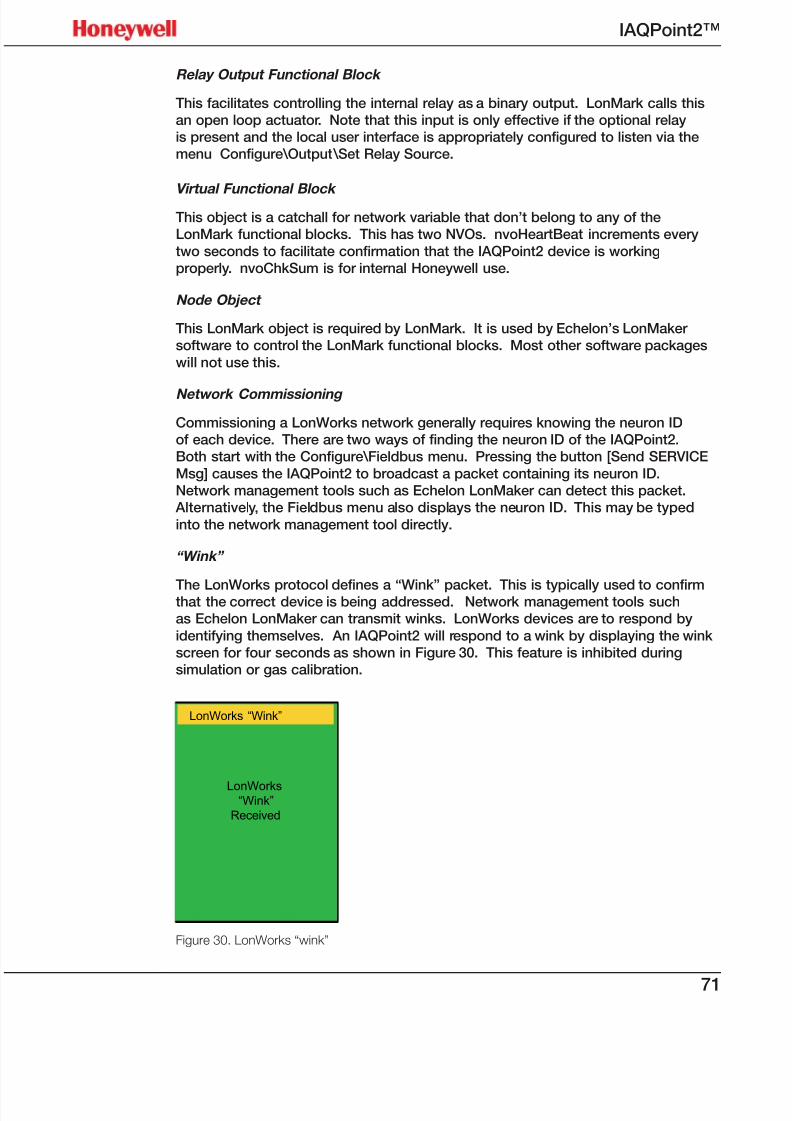
7/23/2019 IAQPoint2 Manual ENG Rev03
http://slidepdf.com/reader/full/iaqpoint2-manual-eng-rev03 73/8071
IAQPoint2™
Relay Output Functional Block
This facilitates controlling the internal relay as a binary output. LonMark calls thisan open loop actuator. Note that this input is only effective if the optional relayis present and the local user interface is appropriately configured to listen via themenu Configure\Output\Set Relay Source.
Virtual Functional Block
This object is a catchall for network variable that don’t belong to any of theLonMark functional blocks. This has two NVOs. nvoHeartBeat increments every
two seconds to facilitate confirmation that the IAQPoint2 device is workingproperly. nvoChkSum is for internal Honeywell use.
Node Object
This LonMark object is required by LonMark. It is used by Echelon’s LonMakersoftware to control the LonMark functional blocks. Most other software packages
will not use this.
Network Commissioning
Commissioning a LonWorks network generally requires knowing the neuron IDof each device. There are two ways of finding the neuron ID of the IAQPoint2.Both start with the Configure\Fieldbus menu. Pressing the button [Send SERVICE
Msg] causes the IAQPoint2 to broadcast a packet containing its neuron ID.Network management tools such as Echelon LonMaker can detect this packet.
Alternatively, the Fieldbus menu also displays the neuron ID. This may be typed
into the network management tool directly.
“Wink”
The LonWorks protocol defines a “Wink” packet. This is typically used to confirmthat the correct device is being addressed. Network management tools suchas Echelon LonMaker can transmit winks. LonWorks devices are to respond by
identifying themselves. An IAQPoint2 will respond to a wink by displaying the winkscreen for four seconds as shown in Figure 30. This feature is inhibited duringsimulation or gas calibration.
LonWorks “Wink”
LonWorks“Wink”
Received
Figure 30. LonWorks “wink”
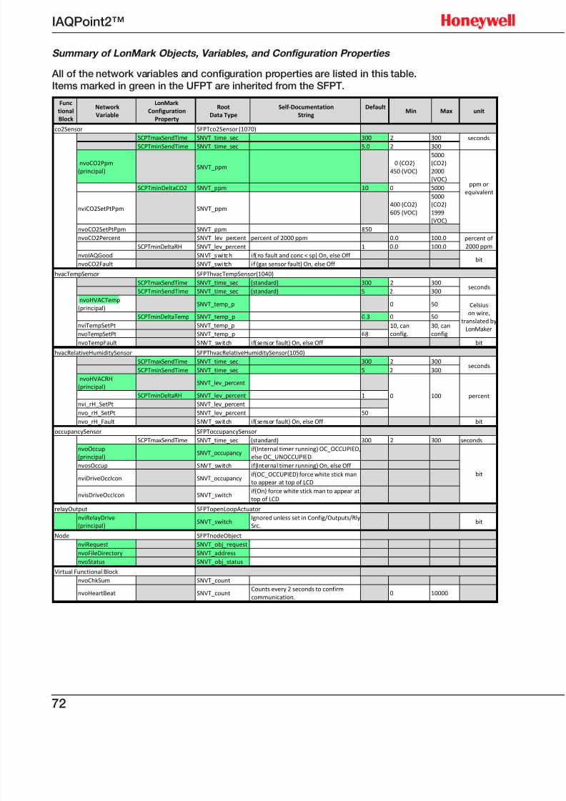
7/23/2019 IAQPoint2 Manual ENG Rev03
http://slidepdf.com/reader/full/iaqpoint2-manual-eng-rev03 74/8072
IAQPoint2™
Summary of LonMark Objects, Variables, and Configuration Properties
All of the network variables and configuration properties are listed in this table.Items marked in green in the UFPT are inherited from the SFPT.
Func
tional
Block
Network
Variable
LonMark
Configuration
Property
Root
Data Type
Self ‐Documentation
String
Default Min Max unit
co2Sensor SFPTco2Sensor (1070)
SCPTmaxSendTime
SNVT_time_sec 300
2
300 seconds
SCPTminSendTime SNVT_time_sec 5.0 2 300
nvoCO2Ppm
(principal) SNVT_ppm
0 (CO2)
450 (VOC)
5000
(CO2)
2000
(VOC) ppm or
equivalent SCPTminDeltaCO2 SNVT_ppm 10 0 5000
nviCO2SetPtPpm SNVT_ppm
400 (CO2)
605 (VOC)
5000
(CO2)
1999
(VOC)
nvoCO2SetPtPpm SNVT_ppm 850
nvoCO2Percent
SNVT_lev_percent percent
of
2000
ppm 0.0
100.0 percent of
2000 ppm SCPTminDeltaRH SNVT_lev_percent 1 0.0 100.0
nvoIAQGood SN VT _s witc h i f(no fault and conc < sp) On, else Off
bit nvoCO2Fault SNVT_swi tch i f (gas sensor fault) On, else Off
hvacTempSensor SFPThvacTempSensor(1040)
SCPTmaxSendTime
SNVT_time_sec (standard) 300
2
300seconds
SCPTminSendTime
SNVT_time_sec (standard) 5 2
300
nvoHVACTemp
(principal) SNVT_temp_p 0 50 Celsius
on wire,
translated by
LonMaker
SCPTminDeltaTemp SNVT_temp_p 0.3 0 50
nviTempSetPt SNVT_temp_p 10, can
config.
30, can
config nvoTempSetPt SNVT_temp_p 68
nvoTempFault SNVT_switch if(sensor fault) On, else Off bit
hvacRelativeHumiditySensor SFPThvacRelativeHumiditySensor(1050)
SCPTmaxSendTime SNVT_time_sec 300 2 300seconds
SCPTminSendTime SNVT_time_sec 5 2 300
nvoHVACRH
(principal) SNVT_lev_percent
0 100 percent SCPTminDeltaRH SNVT_lev_percent 1
nvi_rH_SetPt SNVT_lev_percent
nvo_rH_SetPt SNVT_lev_percent 50
nvo_rH_Fault
SNVT_switch if(sensor
fault)
On,
else
Off
bit
occupancySensor SFPToccupancySensor
SCPTmaxSendTime SNVT_time_sec (standard) 300 2 300 seconds
nvoOccup
(principal) SNVT_occupancy
if(Internal timer running) OC_OCCUPIED,
else OC_UNOCCUPIED.
bit
nvosOccup SNVT_switch if(Internal timer running) On, else Off
nviDriveOccIcon SNVT_occupancy
if(OC_OCCUPIED) force white stick man
to appear at top of LCD
nvisDriveOccIcon SNVT_switch
if(On) force white stick man to appear at
top of LCD
relayOutput SFPTopenLoopActuator
nviRelayDrive
(principal) SNVT_switch
Ignored unless set in Config/Outputs/Rly
Src. bit
Node SFPTnodeObject
nviRequest SNVT_obj_request
nvoFileDirectory SNVT_address
nvoStatus
SNVT_obj_status
Virtual Functional Block
nvoChkSum SNVT_count
nvoHeartBeat SNVT_count Counts every 2 seconds to confirm
communication. 0 10000
7/23/2019 IAQPoint2 Manual ENG Rev03
http://slidepdf.com/reader/full/iaqpoint2-manual-eng-rev03 75/8073
IAQPoint2™
Limited Warranty
Honeywell Analytics, Inc. warrants to the original purchaser and/or ultimate customer(“purchaser”) of Honeywell products (“product”) that if any part thereof proves tobe defective in material or workmanship within one year, such defective part will berepaired or replaced, free of charge, at Honeywell Analytics’ discretion if shippedprepaid to Honeywell Analytics at 405 Barclay Boulevard, Lincolnshire, Illinois, USA60069, in a package equal to or in the original container. The Product will be returnedfreight prepaid and repaired or replaced if it is determined by Honeywell Analyticsthat the part failed due to defective materials or workmanship. The repair or replace-ment of any such defective part shall be Honeywell Analytics’ sole and exclusiveresponsibility and liability under this limited warranty.
Restocking Policy
The following re-stocking fees apply when customers return products for credit: A 15% re-stocking fee will be applied if the product is returned within 1 month of theshipping date.
A 30% re-stocking fee will be applied if the product is returned within 3 months of theshipping date.
A full credit (less re-stocking fee) will be issued only if the product is in like-new con-dition. If repairs are required on the returned product, the cost of these repairs will bededucted from the credit issued.
No credits will be issued beyond the three month period.
Exclusions
If a gas sensor is part of the Product, it is covered by the manufacturer’s twelve-month limited warranty.If a gas sensor is covered by this limited warranty, and a claim by the Purchaser ismade under this limited warranty, the sensor is subject to inspection by Honeywell
Analytics for extended exposure to excessive gas concentrations. If this inspec-tion indicates that the gas sensor has been expended rather than failed prema-turely, this limited warranty shall not apply to the Product.This limited warranty does not cover consumable items, such as batteries, oritems subject to wear or periodic replacement, including lamps, fuses, valves,vanes, sensor elements, cartridges, or filter elements.
Warranty Limitation and Exclusion
Honeywell Analytics has no further obligation under this limited warranty. All war-ranty obligations of Honeywell Analytics are void if the Product has been subjectto abuse, misuse, negligence, or accident or if the Purchaser fails to perform anyof the duties set forth in this limited warranty or if the Product has not been oper-ated in accordance with instructions, or if the Product serial number has beenremoved or altered.
Disclaimer of Unstated Warranties
The warranty in this document is the only warranty applicable to this purchase. Allother warranties, express or implied, including, but not limited to, the implied war-ranties of merchantability or fitness for a particular purpose are hereby disclaimed.
Limitation of Liability
It is understood and agreed that Honeywell Analytics’ liability, whether in contract,in tort, under any warranty, in negligence or otherwise shall not exceed the amountpaid by the purchaser for the product and under no circumstances shall Honeywell
Analytics be liable for special, indirect, or consequential damages. The pricestated for the product is a consideration limiting Honeywell Analytics’ liability. Noaction, regardless of form, arising from the transactions under this warranty maybe brought by the purchaser more than one year after the cause of actions hasoccurred.

7/23/2019 IAQPoint2 Manual ENG Rev03
http://slidepdf.com/reader/full/iaqpoint2-manual-eng-rev03 76/8074
IAQPoint2™
7/23/2019 IAQPoint2 Manual ENG Rev03
http://slidepdf.com/reader/full/iaqpoint2-manual-eng-rev03 77/8075
IAQPoint2™
Index
301C controller 38
A
ABC, see automatic baselinecorrection 7
accuracy of measurements 22acetaldehyde 4addresses, communications
31 Africa 6air movement 22aldehyde 7
American Wire Gauge 7analog 8, 35
ASHRAE 7
Asia Pacic 6automatic baseline correction
7, 25 Automatic Baseline screen 36automatic baseline vorrection
24 AWG, see American Wire
Gauge
B
BACnet 7, 31, 39, 59, 64baud rate 31binary outputs 33buttons 29, 30
C
CA-24, see California Code ofRegulations
Calibrate Gas screen 40Calibrate mA Output screen 42
Calibrate screen 40calibration 26, 44CO2 44kit 12, 20milliamp output 39rH 46strategy 25temperature 45
VOC 45California Code of Regulations
7
Cal rH screen 42Cal Temperature screen 41Canada 6Canadian Standards Associa-
tion 7carbon monoxide 4, 7caution 5
Celcius 37CE, see Conformité Europée- nne
cleaning 55CO2 8
Full Scale screen 34in fresh air 25sensor, calibration 24Setpoint screen 33
commissioning 24Conguration 7, 31
base 8
eldbus 39CO2 24 VOC 24
Congure Display screen 37Congure Fieldbus screen 38Congure Password screen 39Congure screen 32Conformité Européenne 7contact information 6contents 1CO, see carbon monoxide
CSA, see Canadian Standards
Association
D
danger 5digital outputs 8, 33dimensions 11DIP switch 7display, default 29display, dimming 37drift 24, 25duct-mount 3duct-mounting procedure 20
E
Easy Temp Adj screen 38Echelon corporation 7ethyl alcohol 4Europe 6
F
Factory Cong. screen 31, 32factory conguration 31, 32factory defaults 39Fahrenheit 37eldbus, digital 31functional blocks 70, 71
G
glossary 7
H
hazardous locations 12Heating, Ventilation, and Air
Conditioning 7
HVAC, see Heating, Ventilation,and Air Conditioning 7hysteresis 7, 31, 33
I
IAQ, see indoor air quality Idle Display Behavior screen
37IEC, see International Electro-
technical Commission indoor air quality 7industrial applications 12inspections, delivery 25installation 11, 20interfaces 25International Electro-technical
Commission 7IP ratings 7, 56
K
Korea 6
L
LCD, see touchscreen LED, see light-emitting diode
light-emitting diode 7LonMaker 69LonMark 7, 72LonWorks 7, 15, 16, 38, 69
7/23/2019 IAQPoint2 Manual ENG Rev03
http://slidepdf.com/reader/full/iaqpoint2-manual-eng-rev03 78/8076
IAQPoint2™
M
Main Display Dataset screen37
Main menu 31maintenance 55master/slave token passing 7Max Temp. Setpoint screen 34menus 26–41methane 4methylethylketone 4Middle East 6Min Temp Setpoint screen 34Modbus 31, 39, 57, 58MS/TP, see master/slave token
passing
N
no display 8non-display 3notes 5
O
operation 24O-ring 21output, analog 31output type, hardware 31
P
parity 31part names 9, 10Password entry screen 30passwords 25, 29, 30, 39performance verication 25PF, see power factor
power factor 7power-up, rst 24propane 4protocol 31
R
Reboot button 40relative humidity 24relay ow 36, 57Reset All Conguration screen
39review screen 31rH Setpoint screen 34RS-485 14, 15, 31
S
sampling tube 21sensor accuracy 24, 25, 44, 55sensor inhibitors 55sensor poisons 55serial numbers 31Set Address screen 39
Set BACnet ID screen 39Set CO2 Full Scale screen 34Set Fieldbus Speed screen 38Set mA Ch2 Function screen
35Set Occupied Timeout screen
35Set Parity screen 39Set Password 1 screen 39Set Password 2 screen 39setpoints 7, 31, 33, 39Setpoints screen 33
Set Protocol screen 38Set Relay Source screen 36Simulate screen 43software version number 31Status screen 32stop bits 39Switzerland 6
T
temperature 11, 24
Temp Setpoint screen 33Temp. Units screen 37timestamp 31toluene 4tools 12, 20touchscreen 8, 25troubleshooting 47
U
UL, see Underwriters’ Labora-
tory
Underwriters’ Laboratory 7User Cong. screen 31
V
vibration 11 VOC, see volatile organic com-
pound
VOC sensor, calibration 24 VOC Setpoint screen 33volatile organic compound 7
W
wall-mount 3warm-up 25warning 5Warranty 73wink 71wiring 11
analog, duct-mount 22analog, wall-mount 18digital, duct-mount 23digital, wall-mount 19schematics 13, 14, 15, 16
Z
zero calibration 46

7/23/2019 IAQPoint2 Manual ENG Rev03
http://slidepdf.com/reader/full/iaqpoint2-manual-eng-rev03 79/80

7/23/2019 IAQPoint2 Manual ENG Rev03
http://slidepdf.com/reader/full/iaqpoint2-manual-eng-rev03 80/80


![Boeing Group Assignment for Improvement[Rev03]](https://img.pdfslide.us/doc/110x75/54f9f3c54a7959575b8b45b4/boeing-group-assignment-for-improvementrev03.jpg)