Embed Size (px)
Citation preview
LA-UR-95- 3 0 4 6 Title:
A uthor(s):
Submitted to:
DI!
THE STRUCTURE, PROPERTIES AND PERFORMANCE OF PLASMA-SPRAYED BERYLLIUM FOR FUSION APPLICATIONS.
Richard G. Castro, M T-6 Paul W. Stanek, MST-6 Keith E. Elliott, MSt-6 Dennis L. Youchison, SNL, Albuquerque Robert D. Watson, SNL, Albuquerque David S. Walsh, SNL, Albuquerque
2nd IEA International workshop on Beryllium Technology for Fusion, Jackson, Wyoming, September 6-8. 1995
7th International workshop on Carbon Materials, Stockholm, Sweden, September 21-22, 1995
31BUTION OF THIS KXXJMENT IS IJNLJ~~~JED ,;+ -
- - - - - - - - - - - - - - - - - - - - - - - - - -- - -- - -
- - - -
- - -- -- -
-- --- -- -. - __- -- L O ~ Alamos N A T I O N A L L A B O R A T O R Y
Los Alamos National Laboratory, an affirmative actiodequal opportunity employer, is operated by the University of California for the U.S. Department of Energy under conlract W-7405-ENG-36. By acceptance of this article, the publisher recognizes that the U.S. Government retains a nonexclusive, royalty-free license to publish or reproduce the publlshed form of this contribution, or to allow others to do so, for U.S. Government purposes. The Los Alamos National Laboratory requests that the publisher Identify this article a s work performed under the auspices of the US. Department of Energy.
DISCLAIMER
Portions of this document may be illegible in electronic image products. Images are produced from the best available original document.
The Structure, Properties and Performance of Plasma-Sprayed Beryllium for Fusion Applications
R.G. Castro, P.W. Stanek, and K.E. Elliott, Los Alamos National Laboratory, Los Alamos, N.M. 87545, USA
D.L. Youchison, R.D. Watson and D.S. Walsh Sandia National Laboratory, Albuquerque, N.M. 871 85, USA
Abstract
Plasma-spray technology is under investigation as a method for producing high thermal conductivity beryllium coatings for use in magnetic fusion applications. Recent investigations have focused on optimizing the plasma-spray process for depositing beryllium coatings on damaged beryllium surfaces. Of particular interest has been optimizing the processing parameters to maximize the through-thickness thermal conductivity of the beryllium coatings. Experimental results will be reported on the use of secondary H2 gas additions to improve the melting of the beryllium powder and transferred-arc cleaning to improve the bonding between the beryllium coatings and the underlying surface. Information will also be presented on thermal fatigue tests which were done on beryllium coated ISX-B beryllium limiter tiles using 10 sec cycle times with 60 sec cooldowns and an International Thermonuclear Experimental Reactor (ITER) relevant divertor heat flux slightly in excess of 5 MW/m2.
1.0 Introduction
Plasma-spraying of beryllium for coating applications in magnetic fusion energy devices will require extensive research and development in order to qualify this technology for in situ and off-site repair. Areas of research which will need to be investigated include; optimizatiodunderstanding of the thermal and physical properties of the beryllium coatings under irradiated and non-irradiated conditions, maximizing the adherence of the beryllium plasma-sprayed coatings to underlying beryllium and/or copper surfaces, reclamation and recycling of the beryllium oversprayed powder, remote manipulation to perform in situ repair, real-time inspection of the process and the deposited coatings, and technology scale-up. Much of the technology of plasma-spraying has been developed through a trial and error approach. This methodology requires extensive experimental plasma-spray trials and metallographic evaluations to arrive at the optimum conditions for providing the required coatings. Due to the limited facilities available to perform beryllium plasma-spray experiments, development of this technology for fusion energy applications must rely on the available technology and. expertise which has been developed for other material systems.
1
Current advances in plasma-spray technology such as plasma-spraying under a reduced pressure, transferred-arc cleaningkpraying and use of hydrogen gas additions into the arc gas, are being implemented in the R&D program to improve the overall quality of the beryllium coatings. The benefits of plasma-spraying under a reduced pressure (i.e., vacuum plasma-spraying) has been discussed extensively by a number of researchers [1,2,3,4]. In general, spraying under a reduced pressure, results in increased velocities of the molten particles exiting from the plasma torch. This can improve the impacting and consolidation of the individual molten particles which make up the bulk of the coating. In addition, spraying in an inert atmosphere at a reduced pressure also provides the ability to spray reactive materials such as beryllium.
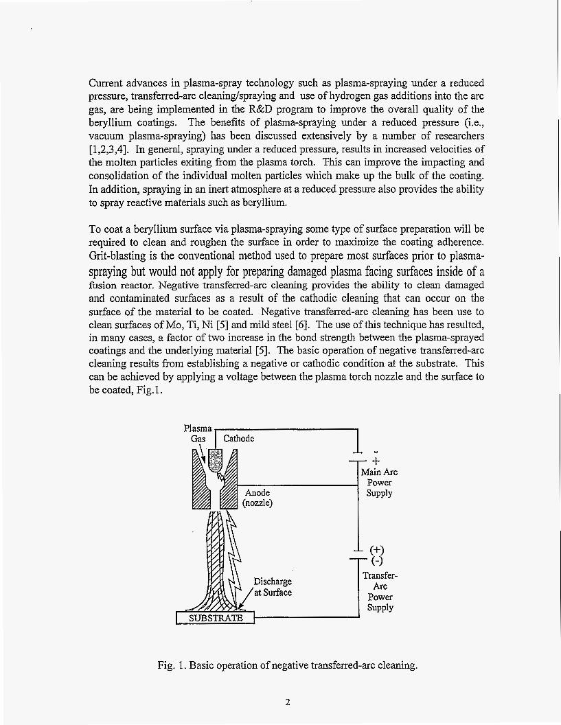
To coat a beryllium surface via plasma-spraying some type of surface preparation will be required to clean and roughen the surface in order to maximize the coating adherence. Grit-blasting is the conventional method used to prepare most surfaces prior to plasma- spraying but would not apply for preparing damaged plasma facing surfaces inside of a fusion reactor. Negative transfen-ed-arc cleaning provides the ability to clean damaged and contaminated surfaces as a result of the cathodic cleaning that can occur on the surface of the material to be coated. Negative transferred-arc cleaning has been use to clean surfaces of Mo, Ti, Ni [5] and mild steel [6]. The use of this technique has resulted, in many cases, a factor of two increase in the bond strength between the plasma-sprayed coatings and the underlying material [5 1. The basic operation of negative transferred-arc cleaning results from establishing a negative or cathodic condition at the substrate. This can be achieved by applying a voltage between the plasma torch nozzle and the surface to be coated, Fig. 1.
Plasma Gas 1 Cathode I
(nozzle) &Ode
1 -
I
Transfer-
Power
Fig. 1. Basic operation of negative transferred-arc cleaning.
2
The mechanism of cleaning results from the formation of microscopic cathode arc spots on the thin dielectric oxide layer present on the metal surface [7,8]. Electrons are emitted from the oxide films as a result of the very high electric fields that exist at each cathode arc spot. Melting of the surface oxides results from the high concentration of electric currents (10’ A/cm2) that are present at these cathode arc spots. This results in the removal of the oxide surface layer exposing a clean metallic surface. Processing conditions which can effect the performance of the negative transferred-arc process are; the composition of the plasma gas, the torch to substrate distance, power levels associated with the plasma torch and the transferred-arc power supply, and the operating pressure in the plasma-spraying chamber. The negative transferred-arc process is described in more detail in reference [9].
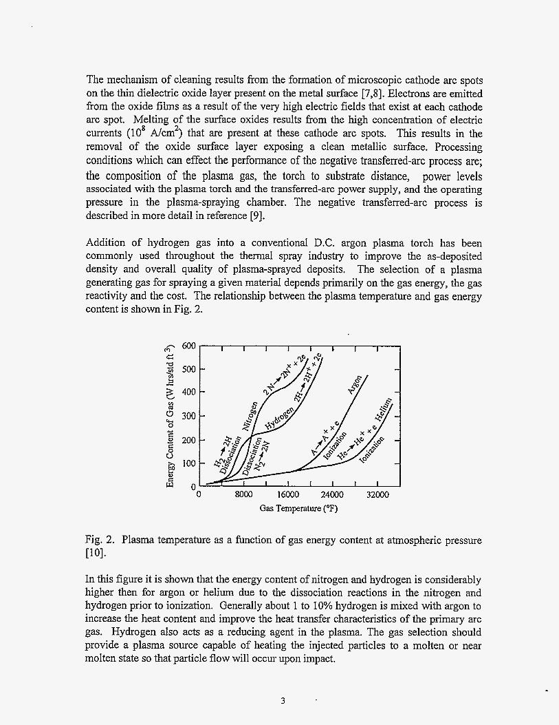
Addition of hydrogen gas into a conventional D.C. argon plasma torch has been commonly used throughout the thermal spray industry to improve the as-deposited density and overall quality of plasma-sprayed deposits. The selection of a plasma generating gas for spraying a given material depends primarily on the gas energy, the gas reactivity and the cost. The relationship between the plasma temperature and gas energy content is shown in Fig. 2.
-- 600 c ‘ 500
3 400
5 300
Y 200
H v v1
cu 0 C
E
Y
6 & 100
s o !ij
0 8000 16000 24000 32000 Gas Temperature (OF)
Fig. 2. Plasma temperature as a function of gas energy content at atmospheric pressure [lo].
In this figure it is shown that the energy content of nitrogen and hydrogen is considerably higher then for argon or helium due to the dissociation reactions in the nitrogen and hydrogen prior to ionization. Generally about 1 to 10% hydrogen is mixed with argon to increase the heat content and improve the heat transfer characteristics of the primary arc gas. Hydrogen also acts as a reducing agent in the plasma. The gas selection should provide a plasma source capable of heating the injected particles to a molten or near molten state so that particle flow will occur upon impact.
3
In this paper, experimental results will be presented on plasma-spraying beryllium with hydrogen gas additions along with the use of negative transferred-arc cleaning to prepare beryllium surfaces prior to depositing beryllium. Discussions will focus on applying beryllium plasma-spray technology for coating beryllium limiter tiles which were used in the ISX-B tokamak experiment at O W L [ll]. Results on the performance of the beryllium coated tiles after thermal cycling the tiles under an ITER relevant heat flux of 5 MW/m2 will also be discussed.
2.0 Experimental Procedure
2.1 Hvdrosen Gas Additions
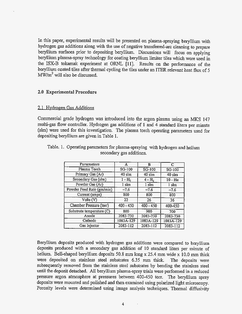
Commercial grade hydrogen was introduced into the argon plasma using an MKS 147 multi-gas flow controller. Hydrogen gas additions of 1 and 4 standard liters per minute (slm) were used for this investigation. The plasma torch operating parameters used for depositing beryllium are given in Table 1.
Table. 1. Operating parameters for plasma-spraying with hydrogen and helium secondary gas additions.
Beryllium deposits produced with hydrogen gas additions were compared to beryllium deposits produced with a secondary gas addition of 10 standard liters per minute of helium. Bell-shaped beryllium deposits 50.8 mm long x 25.4 mm wide x 10.0 mm thick were deposited on stainless steel substrates 6.35 mm thick. The deposits were subsequently removed fiom the stainless steel substrates by bending the stainless steel until the deposit detached. All beryllium plasma-spray trials were performed in a reduced pressure argon atmosphere at pressures between 400-450 torr. The beryllium spray deposits were mounted and polished and then examined using polarized light microscopy. Porosity levels were determined using image analysis techniques. Thermal diffusivity
4
samples 3 mm thick x 12.7 mm in diameter, were machined from each spray deposit and tested at Virginia Polytechnic Institute, Thermophysical Research Laboratory, Blacksburg, Virginia, using laser flash difisivity. The thermal conductivity was determined using the following relationship:
where p is the density and Cp is the heat capacity and D is the thermal diffusivity. Prior to the thermal conductivity measurements, the density of each sample was determined using a water immersion technique (Archimedes principle). All beryllium plasma spray trials performed in this investigation were done using a selective size fraction of -38 +10 pm gas atomized beryllium powder produced commercially by Brush Wellman Inc.
2.2 Negative Transferred-Arc Cleaning
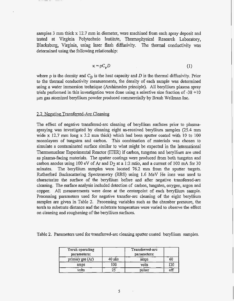
The effect of negative transferred-arc cleaning of beryllium surfaces prior to plasma- spraying was investigated by cleaning eight as-received beryllium samples (25.4 mm wide x 12.7 mm long x 3.2 mm thick) which had been sputter coated with 10 to 100 monolayers of tungsten and carbon. This combination of materials was chosen to simulate a contaminated surface similar to what might be expected in the International Thermonuclear Experimental Reactor (ITER) if carbon, tungsten and beryllium are used as plasma-facing materials. The sputter coatings were produced from both tungsten and carbon anodes using 100 eV of Ar and D2 at a 1:2 ratio, and a current of 100 mA for 30 minutes. The beryllium samples were located 76.2 mm from the sputter targets. Rutherford Backscattering Spectrometry (RBS) using 1.6 MeV He ions was used to characterize the surface of the beryllium' before and after negative transferred-arc cleaning, The surface analysis included detection of carbon, tungsten, oxygen, argon and copper. All measurements were done at the centerpoint of each beryllium sample. Processing parameters used for negative transfer-arc cleaning of the eight beryllium samples are given in Table 2. Processing variables such as the chamber pressure, the torch to substrate distance and the substrate temperature were varied to observe the effect on cleaning and roughening of the beryllium surfaces.
Table 2. Parameters used for transferred-arc cleaning sputter coated beryllium samples.
Torch operating Transferred-arc parameters: parameters:
primary gas (Ar) 40 sim volts
volts Dulser off
5
Sample distance(cm)
chamber pressure (torr)
substratetemp"C
2.3 Coating of the ISX-B Beryllium Limiter Tiles
1 2 3 4 5 6 7 8 7.62 10.16 7.62 7.62 7.62 7.62 10.16 10.16
84 100 30 250 100 100 100 250 375 250 500 450 350 410 450 450
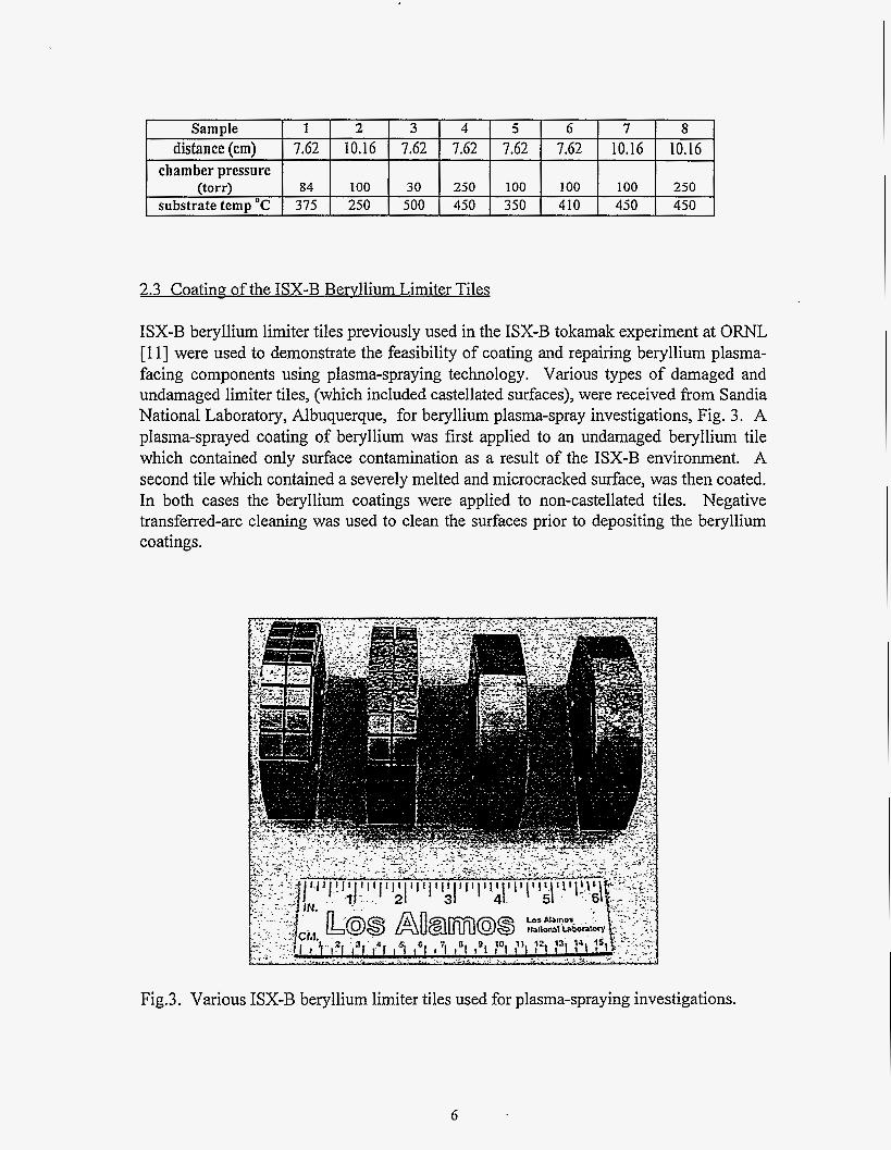
ISX-B beryllium limiter tiles previously used in the ISX-B tokamak experiment at ORNL [ 1 13 were used to demonstrate the feasibility of coating and repairing beryllium plasma- facing components using plasma-spraying technology. Various types of damaged and undamaged limiter tiles, (which included castellated surfaces), were received from Sandia National Laboratory, Albuquerque, for beryllium plasma-spray investigations, Fig. 3. A plasma-sprayed coating of beryllium was first applied to an undamaged beryllium tile which contained only surface contamination as a result of the ISX-B environment. A second tile which contained a severely melted and microcracked surface, was then coated. In both cases the beryllium coatings were applied to non-castellated tiles. Negative transferred-arc cleaning was used to clean the surfaces prior to depositing the beryllium coatings.
Fig.3. Various ISX-B beryllium limiter tiles used for plasma-spraying investigations.
6
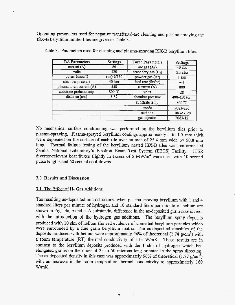
Operating parameters used for negative transfened-arc cleaning and plasma-spraying the ISX-B beryllium limiter tiles are given in Table 3.
Table 3. Parameters used for cleaning and plasma-spraying ISX-B beryllium tiles.
No mechanical surface conditioning was performed on the beryllium tiles prior to plasma-spraying. Plasma-sprayed beryllium coatings approximately 1 to 1.5 mm thick were deposited on the surface of each tile over an area of 25.4 mm wide by 50.8 mm long. Thermal fatigue testing of the beryllium coated ISX-B tiles was performed at Sandia National Laboratory’s Electron Beam Test System (EBTS) Facility. ITER divertor-relevant heat fluxes slightly in excess of 5 MW/m2 were used with 10 second pulse lengths and 60 second cool-downs.
3.0 Results and Discussion
3.1 The Effect of H2 Gas Additions -
The resulting as-deposited microstructures when plasma-spraying beryllium with 1 and 4 standard liters per minute of hydrogen and 10 standard liters per minute of helium are shown in Figs. 4a, b and c. A substantial difference in the as-deposited grain size is seen with the introduction of the hydrogen gas additions. The beryllium spray deposits produced with 10 slm of helium showed evidence of m e l t e d beryllium particles which were surrounded by a fine grain beryllium matrix. The as-deposited densities of the deposits produced with helium were approximately 94% of theoretical (1.74 g/cm3) with a room temperature (RT) thermal conductivity of 115 W/mK. These results are in contrast to the beryllium deposits produced with the 1 slm of hydrogen which had elongated grains on the order of 25 to 50 microns long oriented in the spray direction. The as-deposited density in this case was approximately 96% of theoretical (1.77 g/cm3) with an increase in the room temperature thermal conductivity to approximately 160 WImK.
7
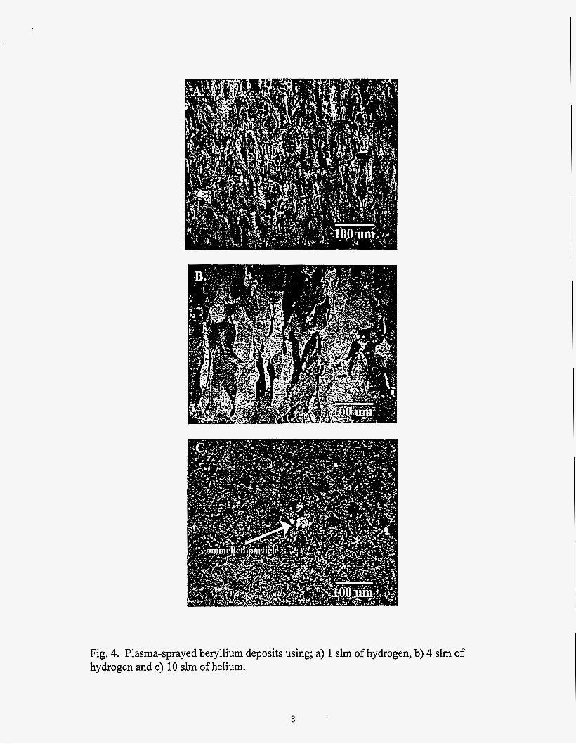
Fig. 4. Plasma-sprayed beryllium deposits using; a) 1 slm of hydrogen, b) 4 slm of hydrogen and c) 10 slm of helium.
8
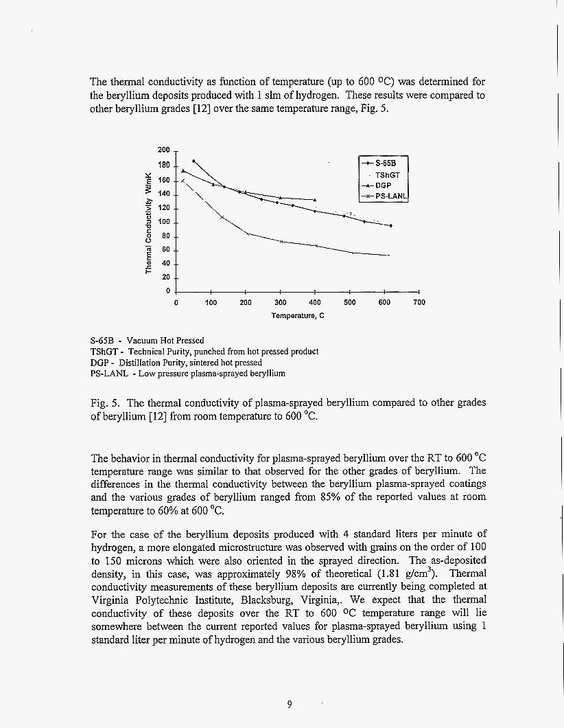
The thermal conductivity as function of temperature (up to 600 OC) was determined for the beryllium deposits produced with 1 slm of hydrogen. These results were compared to other beryllium grades [12] over the same temperature range, Fig. 5.
160
140 2. '5 120 .- Y s 100 U K 0 80 0 a 60 -- 2 40 -_
20 --
- E I-
200
180 1 _ _ _ _ -- -- - -
El 4- DGP
0 4 I
0 100 200 300 400 500 600 700 Temperature, C
S-65B - Vacuum Hot Pressed TShGT - Technical Purity, punched from hot pressed product DGP - Distillation Purity, sintered hot pressed PS-LANL - Low pressure plasma-sprayed beryllium
Fig. 5. The thermal conductivity of plasma-sprayed beryllium compared to other grades of beryllium [ 121 from room temperature to 600 "C.
The behavior in thermal conductivity for plasma-sprayed beryllium over the RT to 600 "C temperature range was similar to that observed for the other grades of beryllium. The differences in the thermal conductivity between the beryllium plasma-sprayed coatings and the various grades of beryllium ranged from 85% of the reported values at room temperature to 60% at 600 "C.
For the case of the beryllium deposits produced with 4 standard liters per minute of hydrogen, a more elongated microstructure was observed with grains on the order of 100 to 150 microns which were also oriented in the sprayed direction. The as-deposited density, in this case, was approximately 98% of theoretical (1.81 g/cm3). Thermal conductivity measurements of these beryllium deposits are currently being completed at Virginia Polytechnic Institute, Blacksburg, Virginia,. We expect that the thermal conductivity of these deposits over the RT to 600 O C temperature range will lie somewhere between the current reported values for plasma-sprayed beryllium using 1 standard liter per minute of hydrogen and the various beryllium grades.
9
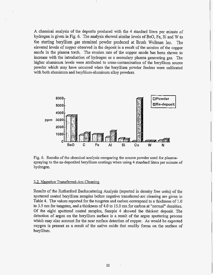
A chemical analysis of the deposits produced with the 4 standard liters per minute of hydrogen is given in Fig. 6. The analysis showed similar levels of BeO, Fe, Si and W to the starting beryllium gas atomized powder produced at Brush Wellman Inc. The elevated levels of copper observed in the deposit is a result of the erosion of the copper anode in the plasma torch. The erosion rate of the copper anode has been shown to increase with the introduction of hydrogen as a secondary plasma generating gas. The higher aluminum levels were attributed to cross-contamination of the beryllium source powder which may have occurred when the beryllium powder feeders were calibrated with both aluminum and beryllium-aluminum alloy powders.
6000
4000
Be0 C Fe AI Si cu W N
Fig. 6 . Results of the chemical analysis comparing the source powder used for plasma- spraying to the as-deposited beryllium coatings when using 4 standard liters per minute of hydrogen.
3.2 Negative Transferred-Arc Cleanins
Results of the Rutherford Backscattering Analysis (reported in density free units) of the sputtered coated beryllium samples before negative transferred-arc cleaning are given in Table 4. The values reported for the tungsten and carbon correspond to a thickness of 1 .O to 3.5 nm for tungsten, and a thickness of 4.0 to 15.0 nm for carbon at "normal" densities. Of the eight sputtered coated samples, Sample 4 showed the thickest deposit. The detection of argon on the beryllium surface is a result of the argon sputtering process which may also account for the near surface detection of copper. As would be expected oxygen is present as a result of the native oxide that readily forms on the surface of beryllium.
10
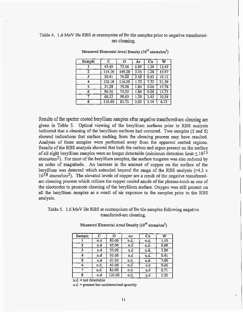
Table 4. 1.6 MeV He RBS at centerpoint of Be tile samples prior to negative transferred- arc cleaning.
I
2 114.10 149.20 3.35 1.28 3 50.41 76.00 2.38 0.63 4 152.10 116.30 1.72 7.72
Measured Elemental Areal Density (10’’ atoms/cm2)
15.97 19.12 21.59
Sample I c l 0 1 Ar I Cu I W 1 I 43.49 I 73.56 I 0.89 I 1.28 I 13.45
5 6
1
37.58 I 79.08 I 1.84 I 0.06 17.78 96.16 I 75.05 I 1.86 I 0.08 12.73
7 8
I
68.55 98.63 1.39 3.45 10.54 116.80 83.73 2.02 5.74 6.73
Results of the sputter coated beryllium samples after negative transferred-arc cleaning are given in Table 5. Optical viewing of the beryllium surfaces prior to RBS analysis indicated that a cleaning of the beryllium surfaces had occurred. Two samples (5 and 8) showed indications that surface melting from the cleaning process may have resulted. Analysis of these samples were performed away fiom the apparent melted regions. Results of the RBS analysis showed that both the carbon and argon present on the surface of all eight beryllium samples were no longer detectable (minimum detection limit 5 1013 atoms/crn2). For most of the beryllium samples, the surface tungsten was also reduced by an order of magnitude. An increase in the amount of copper on the surface of the beryllium was detected which extended beyond the range of the RBS analysis (>4.2 x 10¹⁸ atoms/cm2). The elevated levels of copper are a result of the negative transfened- arc cleaning process which utilizes the copper cooled anode of the plasma-torch as one of the electrodes to promote cleaning of the beryllium surface. Oxygen was still present on all the beryllium samples as a result of air exposure to the samples prior to the RBS analysis.
7 n.d. 83.00 n.d. 8 n.d 120.00 n.d.
Table 5. 1.6 MeV He RBS at centerpoints of Be tile samples following negative transferred-arc cleaning.
u.d 0.7 1 u.d 1.30
Measured Elemental Areal Density (10” atomskm’)
65.00 0.68 u.d. 3.00 u.d. 0.41
5 I n.d I 61.00 I n.d. I u.d. I 7.00 ~
6 I n.d. I 43.00 I n.d. I u.d I 9.60
11
3.3 Thermal Fatigue of Beryllium Coated ISX-B Beryllium Limiter Tiles
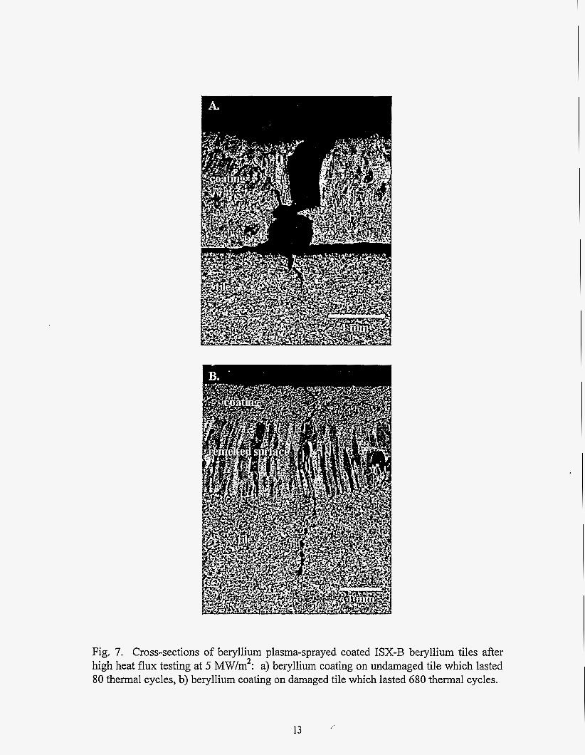
Despite the fact that the beryllium plasma spray process was not completely optimized for this demonstration, the coating on an undamaged beryllium limiter tile survived approximately 80 cycles at 5 MW/m2 for 10 sec pulses before cracking was observed in the coating which led to the formation of hot spots on the surface of the coating. The beryllium coating which was applied to the badly melted ISX-B tile, however, survived 500 cycles before cracking was observed and a total of 680 cycles before the formation of hot spots on the coating surface terminated the tests. A cross-section of each tile is shown in Fig. 7. a and b. The coating which lasted 80 cycles showed thermal fatigue cracks which propagated through the thickness of the beryllium coating and then turned 90' an extended along the interface between the coating and the tile surface. The formation of hot spots on the coating surface was a result of the delamination of the coating from the beryllium tile leading to poor thermal conduction across the coatingtile interface. The microstructural features of the coating showed intermixed regions of columnar grains approximately 15 to 25 microns long adjacent to a fine equiax microstructure. The coating thickness was approximately 1.5 mm thick with a porosity level on the order of 7 percent.
For the case of the beryllium coating which lasted 680 cycles, thermal fatigue cracks which propagated through the thickness of the coating extended into the previously remelted surface region of the damaged beryllium tile and proceeded along the columnar grain boundaries of the remelted zone. There were no indications that any delamination occurred between the beryllium coating and the tile surface. The improved performance of the beryllium coating on the damaged ISX-B tile was attributed to the preferential grain boundary separation that occured along the columnar grains present in the remelted layer on the surface of the damaged tile. The microstructural features of the beryllium coating showed a fine equiax grain structure with no presence of columnar growth indicating that the substrate temperature during spraying might have been lower than what was observed for the beryllium coating on the undamaged beryllium limiter tile. The porosity level of the coating in this case was on the order of 12 percent with a 1 mm thick coating.
Surface temperature measurements done at Sandia National Laboratory during the EBTS high heat flux testing indicated that the coating on the undamaged beryllium surface was lower by approximately 100 OC after the initial thermal cycles. This indicated that the beryllium coating on the undamaged limiter tile was more effective in initially conducting the heat away form the surface during the high heat flux testing. The presence of the intermixed columnadequiax grain structure, the lower porosity in the coating and a potentially better bond between the coating and the substrate may have contributed to an overall higher thermal conductivity. In general, the beryllium coating on the surface of the damaged beryllium ISX-B limiter tile which lasted 680 cycles, was of lower quality then the coating on the undamaged ISX-B tile which lasted only 80 thermal cycles. Clearly, there are other factors influencing the structural performance than simply the quality of the beryllium coating.
12
B. .
Fig. 7. Cross-sections of beryllium plasma-sprayed coated ISX-B beryllium tiles after high heat flux testing at 5 MW/m2: a) beryllium coating on undamaged tile which lasted 80 thermal cycles, b) beryllium coating on damaged tile which lasted 680 thermal cycles.
13
4.0 Conclusions
Secondary additions of 1 and 4 standard liters per minute of hydrogen gas into the plasma-torch significantly influenced the as-deposited microstructure of plasma- sprayed beryllium resulting in long columnar grains in the direction of spraying. The presence of these columnar grains resulted in a dramatic improvement in the through thickness thermal conductivity of the plasma-sprayed beryllium coatings from 1 15 W/mK to 160 W/mK.
Negative transferred-arc cleaning of beryllium was used to remove sputtered coated carbon and tungsten from the beryllium surface. The carbon was reduced below 1013 atomdcm2 which was the detection limit for the RBS analysis technique and the sputter coated tungsten was reduced by an order of magnitude.
The performance of the beryllium plasma-sprayed coatings on two ISX-B limiter tiles after thermal cycling the tiles between 10 sec cycle times with 60 sec cooldowns at an ITER relevant divertor heat flux slightly in excess of 5 MW/m2 were as follows: 1) the beryllium coating on the previously undamaged ISX-B tile lasted 80 thermal cycles before hot spots formed on the coating surface 2) the beryllium coating on the previously severely melted ISX-B tile lasted 680 thermal cycles before the test was terminated due to the formation of hot spots on the coating surface. Based on the results of the two coated ISX-B tiles, an improved performance of the beryllium coating on the damaged ISX-B tile was attributed to grain boundary separation along the columnar grains present in the remelted layer on the surface of the damaged tile.
Acknowledgments
The authors would like to thank the following people for their contributions: Dr. Donald Cowgill of Sandia National Laboratory, Livermore CA for sputter coating the beryllium samples, Dr. D.P.H. Hassleman of Virginia Polytechnic Institute for thermal conductivity measurements, Ann Kelly for metallographic sample preparation and Raul Brunner for machining of thermal conductivity samples. The authors would also like to acknowledge the DOE Office of Fusion Energy for sponsoring this research.
References
1. D.Apelian, R. W. Smith, M. Paliwal and W.R. Schilling, International Metals Review,
2. D. Apelian, and D. Wei, Thin Solid Films, 118, (1984) pp. 395-407. 3. D. Wei, Ph.D Thesis, “Melting Powder Particles in D.C. and R.F. Plasmas: A
Modeling Study” Drexel University, Philadelphia PA, (1 987). 4. M.F. Smith, and R.C. Dykhuizen, Surface and Coating Technology, 34, (1988), pp.
28 ( 5 ) (1983) pp. 271-294.
25-3 1.
14
5. R. Heme, M.V. Bradeke, G. Schiller, W. Schnumberger and W. Weber, “Vacuum Plasma Spraying of Oxide Electrocatalytic Materials”, Proceeding of 12th International Thermal Spray Conference, (1 989).
6. A. Itoh, K. Takeda, M. Itoh and M. Koga “Pretreatment of Substrates by Using Reversed Transfened Arc in Low Pressure Plasma Spray”, Proceeding of the 3rd National Thermal Spray Conference, Long Beach, CAY May 1990, pp. 245-25 1.
7. A.E. Guile and B. Juttner, IEEE Trans.on Plasma Science, vol. PS-8, (3) (1 980). pp. 259-269.
8. A.E. Guile, “Electric Arc-Phenomena”, Proc. IEE, IEE Reviews, Vol 1 18 (9R) (1 97 1) pp. 1131-1 154.
9. E,-Muehlberger, U.S. Patent No. 4,328,257 (1 982). 10. D.A. Gerdeman and N.L. Hecht, Arc Plasma Technology in Material Science,
Springer-Verlag, New York Wien (1 972) pp. 10. 1 1. P.K. Mioduszewski et. al., “The Beryllium Limiter Experiment in ISX-By’, Nuclear
Fusion, 26(9) (1986) pp. 1171. 12. V. Barabash, “Recommended Data on Be Thermomechanical Properties for Plasma
Facing Components: Design Evaluation” ITER Draft Report NGl , F’ irst Edition, ITER Garching Joint Work Site, May 1994, pp.7.
DISCLAIMER
This report was prepared as an amount of work sponsored by an agency of the United States Government. Neither the United States Government nor any agency thereof, nor any of their employees, makes any warranty, express or implied, or assums any legal liability or responsi- bility for the accuracj, completeness, or usefulness of any information, apparatus, product, or process disclosed, or represents that its use would not infringe privately owned rights. Refer- ence herein to any specific commercial product, process, or service by trade name, trademark manufacturer, Or otherwise does not necessady ConstitUte Or imply its edol%ment, recorn- mendation, or favoring by the United States Government Or any agency thereof. The views and opinions of authors expressed herein do not necessarily state or reflect those Of the United States Government or any agency thereof.
15

![Table of Contents · spa hiperenlace n.m. [ESP] spa vínculo activo n.m. [ARG] cat enllaç actiu n.m. cat hiperenllaç actiu n.m. por ponteiro ativo s.m por ponteiro selecionado s.m](https://img.pdfslide.us/doc/110x75/600543b350776360f7282e00/table-of-contents-spa-hiperenlace-nm-esp-spa-vnculo-activo-nm-arg-cat.jpg)