Embed Size (px)
Citation preview

Thermal Stress Analysis of TPS using Marc Ted B. Wertheimer, MSC.Software (Sunnyvale, USA) Fabrice Laturelle, Snecma Moteurs (Bordeaux,Fr.) Abstract Design of solid rocket motors requires an extensive knowledge of the thermal and structural behavior for reliability and optimization of the payload. Within a solid rocket motor, a complex thermo-chemical-aerodynamic process occurs. During the launch, the combustion of the solid propellant generates intense heat, often reaching 3600 K. This results in a thermal decomposition of the combustion chamber housing and the nozzle due to pyrolysis, and the ablation/erosion of these latter due to thermal, chemical, and mechanical processes. Both the thermal strains and externally applied loads can result in large stresses that may have negative consequences on the structural integrity. This paper is a continuation of the work discussed at TFAWS 2004, but focuses on the numerical simulation of the structures undergoing these phenomena. Introduction
Snecma Moteurs, Rocket Motors Division, through its subsidiaries Europropulsion and G2P, is the prime contractor for developing the solid propellant rocket motors of Ariane 5 launchers. It is also involved in the development of nozzle exit cones for liquid rocket motors such as the PW RL-10 motor equipping the Boeing Delta 3 launcher. Snecma Moteurs also develops thermal protection systems for reentry vehicles and bodies, and spatial probes.
What these products have in common is that some parts are subject to very high thermal fluxes (both convective and radiative), thermochemical oxidation by reactive chemical species, sometimes large mechanical and thermomechanical loads, and mechanical and chemical interactions with impacting liquid and solid particles. These loads have their origin in the high temperature, highly reactive and often particle laden surrounding flow generated either by the combustion of the fuel or by the speed of the vehicle.
To sustain such conditions, these motors and vehicles use advanced composite materials, such as carbon/carbon composites, carbon/phenolic composites, silica/phenolic composites, ceramic matrix composites, and reinforced rubber-like materials as shown above. Among these materials, some are thermodegradable and undergo a chemical transformation known as pyrolysis producing decomposition gases and possibly brittle solid residue. Also, those materials and others which are not thermodegradable can undergo surface recession, due to heterogeneous chemical reactions with the oxidizing chemical species of the surrounding flow, in which case we speak of thermochemical ablation or due to mechanical erosion by different mechanical loads. Also, thermochemical ablation and mechanical erosion can occur due to particle impacts.

Previous works have discussed the thermal behavior in detail and only a short summary will be presented here. 1. Poro-thermal and ablative behavior of thermodegradable material
Let us consider, for instance, the case of a carbon/phenolic material used as a thermal protection liner in solid rocket motors. When such a material is exposed to a high thermal flux and chemically reactive environment, thermal degradation occurs and its structure changes as shown.
Starting from the rear side of the material opposite to the heated face, we find first, a nondegraded low temperature zone, with original low porosity and permeability, where thermal evaporation of trapped chemical species as water occurs [1-2]. This produces a high internal pore pressure.
At higher temperature range (300°C – 600°C) for solid propulsion heating rate conditions, the primary pyrolysis chemical reactions occur, turning the long polymer chains constituting the resin matrix into high molecular weight gaseous chemical species, and a carbonaceous solid residue [3-5]. In this zone, a pore pressure also develops although the porosity and the permeability of the material are increasing rapidly due to the loss of solid mass. The solid density decreases.
This pore pressure induces a flow of the rather cool gaseous products through the residue toward the heated surface upstream the heat flux, producing a cooling internal convection effect.
As higher temperatures are encountered (1000°C-1400°C), the thermal cracking of the gaseous phase continues further, generating less molecular weight chemical species. An important phenomenon is the so-called coking [6]. The flowing gaseous products are introducing too much carbon than the chemical equilibrium allows at these temperatures. Hence, a solid carbon deposit in the residue is observed, which can reduce the porosity and the permeability, and again increase the local density left by the primary pyrolysis. This latter effect increases the resistance of the material to the thermochemical ablation discussed below.
Just below the heated surface, where the temperature can reach the range of 2500°C-2800°C, the thermodynamic conditions and the chemical species available in the internal gas
flow change the direction of heterogeneous gas/solid reactions. There, instead of a carbon being deposited by coking, the carbon of the residue is now turned into gaseous species. At the surface itself, the external flow around the part contains similar gaseous chemical species, such as water vapor and carbon dioxide. Globally, the heterogeneous chemical reactions between these species at the solid surface and just below lead to a mass loss. This is known as thermochemical ablation and results in a recession of the surface. Numerous papers and books are devoted to this phenomenon, for instance [3,7-13]. The process can be controlled either by chemical kinetics or by the rate of diffusion of the chemical species through the boundary layer of the external flow, depending on the local temperature and flow conditions.
Ablation absorbs a great quantity of energy, as the water evaporation and pyrolysis reactions do. Another influence on the heat transfer reduction is due to the blowing of the boundary layer of the external flow by the gaseous products of thermal decomposition and ablation. With the above-mentioned internal convection cooling effect, these phenomena explain why these materials exhibit excellent thermal insulation properties.
Besides these chemical processes, if the residue is brittle, mechanical or dynamical loads can erode it [10-11]. Mechanical erosion is important for instance in the case of rubber-like materials used as internal thermal protection for the combustion chamber of the solid rocket motor.
As the combustion of solid propellant produces liquid or solid alumina particles, these latter can impact the walls of the motor and cause additional thermochemical ablation or mechanical erosion depending on the impact conditions. Impacts are also encountered in other applications of these materials [11].
2. Short description of thermal modeling techniques
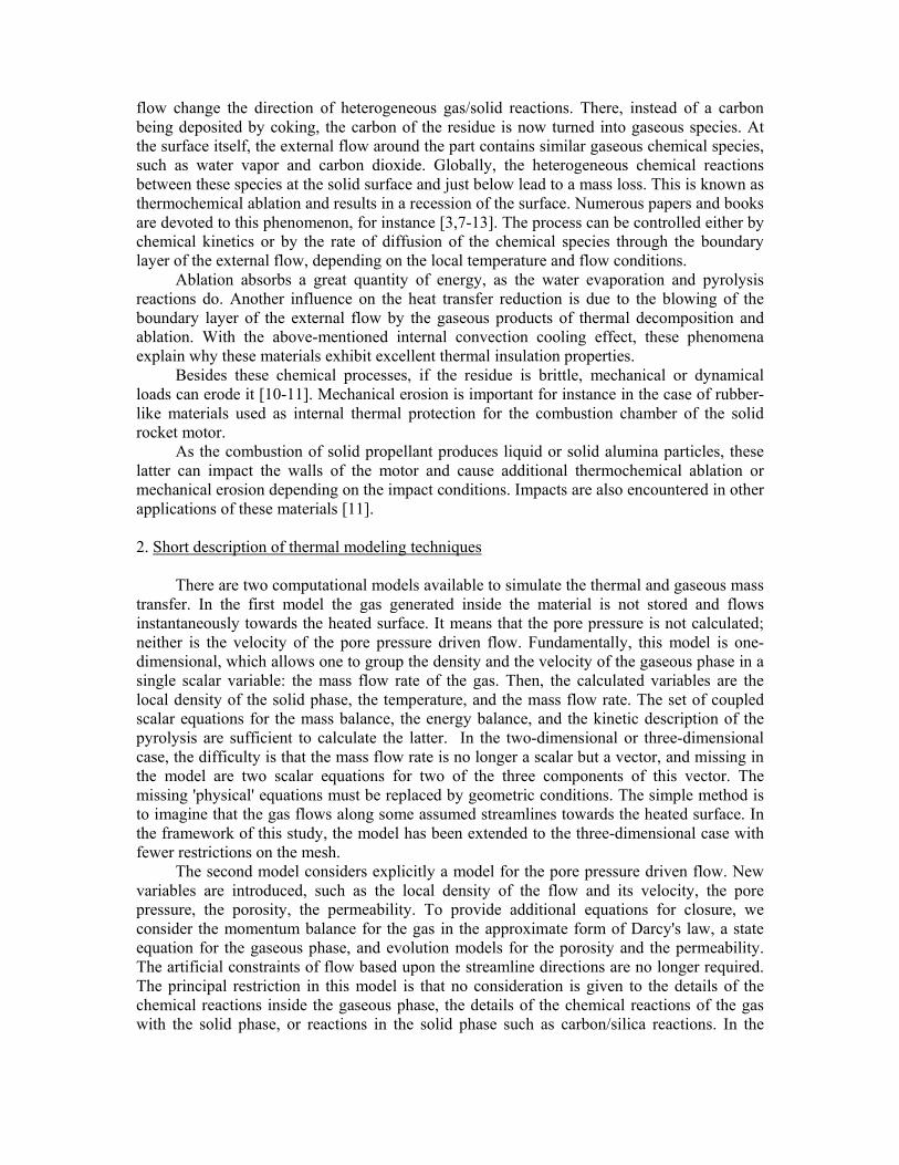
There are two computational models available to simulate the thermal and gaseous mass
transfer. In the first model the gas generated inside the material is not stored and flows instantaneously towards the heated surface. It means that the pore pressure is not calculated; neither is the velocity of the pore pressure driven flow. Fundamentally, this model is one-dimensional, which allows one to group the density and the velocity of the gaseous phase in a single scalar variable: the mass flow rate of the gas. Then, the calculated variables are the local density of the solid phase, the temperature, and the mass flow rate. The set of coupled scalar equations for the mass balance, the energy balance, and the kinetic description of the pyrolysis are sufficient to calculate the latter. In the two-dimensional or three-dimensional case, the difficulty is that the mass flow rate is no longer a scalar but a vector, and missing in the model are two scalar equations for two of the three components of this vector. The missing 'physical' equations must be replaced by geometric conditions. The simple method is to imagine that the gas flows along some assumed streamlines towards the heated surface. In the framework of this study, the model has been extended to the three-dimensional case with fewer restrictions on the mesh.
The second model considers explicitly a model for the pore pressure driven flow. New variables are introduced, such as the local density of the flow and its velocity, the pore pressure, the porosity, the permeability. To provide additional equations for closure, we consider the momentum balance for the gas in the approximate form of Darcy's law, a state equation for the gaseous phase, and evolution models for the porosity and the permeability. The artificial constraints of flow based upon the streamline directions are no longer required. The principal restriction in this model is that no consideration is given to the details of the chemical reactions inside the gaseous phase, the details of the chemical reactions of the gas with the solid phase, or reactions in the solid phase such as carbon/silica reactions. In the

framework of this project, the resulting set of coupled partial differential equations is solved by the finite element method.
In the first model the flow rate is integrated along geometrical streamlines to represent simplified one-dimensional fluid flow. The program, based upon the assumption that a regular but not necessarily uniform mesh is provided for regular two- or three-dimensional analysis, automatically calculates the streamlines. Certain quantities are evaluated at the stream integration points (SIP), shown in the figure below. Unfortunately, finite elements impose the requirements that these quantities are at the conventional integration points to evaluate the material properties, and other source terms. Hence, first a weighted nodal average of the extrapolated quantities are, obtained followed by interpolating to the conventional integration points. Because of the large number of elements through the thickness, this procedure did not show any loss in accuracy.
3. Mechanical Behavior Previously the finite element method was used to solve the poro-thermal problem
described here, without including mechanical behavior. If a structural analysis was required the temperatures were applied in a subsequent analysis so there was effectively only a one-way coupling. The temperature would influence the structure via temperature dependent mechanical properties and via thermal strains. Additionally, the change in shape due to ablation may be considered. This paper introduces additional coupling between the two problems. For instance, the influence of the state of deformation upon the permeability, and, hence, upon the pore pressure, is taken into account. Note that this kind of model requires a very large amount of material characterization. Ablation
An important aspect of modeling thermal protection systems is examining the consequences of surface recession by ablation. Both gases and impacting particles contribute to a chemical ablation that can be expressed by:

Spthsgthsth mms ρ/)( ,,,, &&& += , with ∑=j
jpjpthpthgths mGfm ,,,,,, &&
where ths& is the recession velocity due to chemical reactions and Sρ the solid density. Besides this thermochemical ablation, mechanical erosion can occur: mecth sss &&& +=
The recession model and the relevant surface are defined in a new RECEDING SURFACE option. This recession rate is evaluated at the surface integration points and a consistent nodal displacement is obtained. If a thermo-pore simulation is performed this is the total displacement, while if this is a coupled thermo-mechanical analysis the ablation displacement needs to be combined with the mechanical displacement.
dtsdudududu mechablmech *&+=+=
Remeshing Because of the significant changes in the geometry relative to finite element
dimensions it is necessary to modify the mesh through the global adaptive meshing procedure. Remeshing occurs when the percentage reduction in element thickness in the direction of the flow exceeds a user defined tolerance. Furthermore, the time step is adaptively controlled among other restraints so that the surface recession distance per time step must be less than a critical dimension. It should be noted that while the element aspect ratio often is greater than 50:1, this does not lead to computational difficulties.
Three methods of remeshing have been implemented: mesh relaxing, mesh stretching and mesh shaving. In the first and second technique, the number of elements remains the same and the nodal coordinates are perturbed in the direction of the normal. This results in equal spacing through the thickness. In the third technique, the outside element is stripped off when it becomes arbitrarily thin. The other elements are left undisturbed. Depending on whether the recession is uniform over the surface, an element will be either fully removed or degenerated to a triangle, followed by subsequent removal. Either method may be advantageous based upon the geometric configuration and the magnitude of the thermal gradient through the thickness. In either case, after the mesh is modified, the elemental data is mapped (rezoned) to the new integration points. A similar process is performed for streamline data. When using such techniques, care must be exercised when viewing conventional results for the history of a nodal quantity is dubious, as the node does not represent a constant material particle. For this reason, special particle tracking options have been developed.
Because the shaver mesher changes the element and node numbers that are on the exterior surface the boundary conditions are applied to the underlying geometry. Using this procedure, all boundary conditions thermal, diffusion and mechanical may be applied to a point, curve (2-D), or surface (3-D). The conventional finite element entities (nodes, element-faces) are attached to the geometric entities. As the finite element model changes, the new mesh is automatically associated with the geometry, and boundary conditions are correctly applied.
Material behavior For materials which are not undergoing pyrolysis any of the Marc material models may be used for both the thermal and mechanical behavior. This includes:
• Hookean elasticity (isotropic, orthotropic or general anisotropic) • Elastic plastic (von Mises yield criteria) with isotropic, kinematic, combined
hardening, power law, Kumar and Johnson-Cook model • Elastic plastic with volumetric effects (Mohr Coulomb, Cam Clay) • Powder material • Rubber material (Mooney-Rivlin, Ogden, Arruda-Boyce, Gent) • General hyperelastic via user subroutine • Simplified nonlinear elasticity based upon table input • Gurson Damage Model • Chaboche
All properties may be temperature dependent and creep may be included.
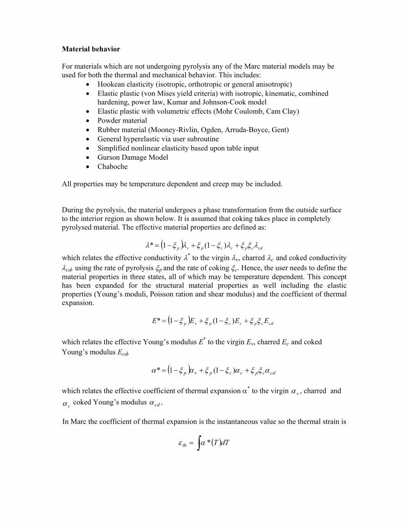
During the pyrolysis, the material undergoes a phase transformation from the outside surface to the interior region as shown below. It is assumed that coking takes place in completely pyrolysed material. The effective material properties are defined as:
( ) cdcpccpvp λξξλξξλξλ +−+−= )1(1*
which relates the effective conductivity λ* to the virgin λv, charred λc and coked conductivity λcd, using the rate of pyrolysis ξp and the rate of coking ξc. Hence, the user needs to define the material properties in three states, all of which may be temperature dependent. This concept has been expanded for the structural material properties as well including the elastic properties (Young’s moduli, Poisson ration and shear modulus) and the coefficient of thermal expansion. ( ) cdcpccpvp EEEE ξξξξξ +−+−= )1(1* which relates the effective Young’s modulus E* to the virgin Ev, charred Ec and coked Young’s modulus Ecd, ( ) cdcpccpvp αξξαξξαξα +−+−= )1(1*
which relates the effective coefficient of thermal expansion α* to the virgin vα , charred and
cα coked Young’s modulus cdα ,
In Marc the coefficient of thermal expansion is the instantaneous value so the thermal strain is
( )∫= dTTth *αε
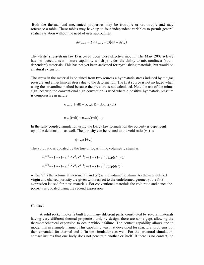
Both the thermal and mechanical properties may be isotropic or orthotropic and may reference a table. These tables may have up to four independent variables to permit general spatial variation without the need of user subroutines. ( )thmechmech ddDDdd εεεσ −== The elastic stress-strain law D is based upon these effective moduli. The Marc 2008 release has introduced a new mixture capability which provides the ability to mix nonlinear (strain dependent) materials. This has not yet been activated for pyrolisizing materials, but would be a natural extension. The stress in the material is obtained from two sources a hydrostatic stress induced by the gas pressure and a mechanical stress due to the deformation. The first source is not included when using the streamline method because the pressure is not calculated. Note the use of the minus sign, because the conventional sign convention is used where a positive hydrostatic pressure is compressive in nature. σmech (t+dt) = σmech(t) + dσmech (dt)
σtot (t+dt) = σmech(t+dt) - p In the fully coupled simulation using the Darcy law formulation the porosity is dependent upon the deformation as well. The porosity can be related to the void ratio (vr ) as φ=vr/(1+vr) The void ratio is updated by the true or logarithmic volumetric strain as vr
n+1= (1 – (1- vr 0)*V0/Vn+1) =(1 – (1- vr
0)/exp(εv) ) or vr
n+1= (1 – (1- vr 0)*Vn/Vn+1) =(1 – (1- vr
n)/exp(dεv) ) where Vi is the volume at increment i and (εv) is the volumetric strain. As the user defined virgin and charred porosity are given with respect to the undeformed geometry, the first expression is used for these materials. For conventional materials the void ratio and hence the porosity is updated using the second expression. Contact
A solid rocket motor is built from many different parts, constituted by several materials having very different thermal properties, and, by design, there are some gaps allowing the thermomechanical expansion to occur without failure. The contact capability allows one to model this in a simple manner. This capability was first developed for structural problems but then expanded for thermal and diffusion simulations as well. For the structural simulation, contact insures that one body does not penetrate another or itself. If there is no contact, no
constraint is imposed. For thermal analysis the flux across a surface is based upon three potential states:
No contact – distance from nodes to another surface dX > dnear :
q= hcv* ( T1-Tenv) ++ σ*ε*(T14-Tenv
4)
Near contact – distance from node to another surface dcontact < dX < dnear
q=hcv*(T2-T1) + hnt* (T2-T1)ent + σ*ε*(T24-T1
4) + (hct –(hct-hbl)*dX* (T2-T1)/dnear
True contact – distance from node to another surface dX < dcontact
q=hct*(T2-T1)
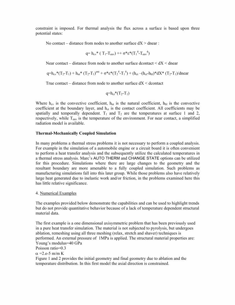
Where hcv is the convective coefficient, hnt is the natural coefficient, hbl is the convective coefficient at the boundary layer, and hct is the contact coefficient. All coefficients may be spatially and temporally dependent. T1 and T2 are the temperatures at surface 1 and 2, respectively, while Tenv is the temperature of the environment. For near contact, a simplified radiation model is available. Thermal-Mechanically Coupled Simulation In many problems a thermal stress problems it is not necessary to perform a coupled analysis. For example in the simulation of a automobile engine or a circuit board it is often convenient to perform a heat transfer analysis and the subsequently utilize the calculated temperatures in a thermal stress analysis. Marc’s AUTO THERM and CHANGE STATE options can be utilized for this procedure. Simulations where there are large changes to the geometry and the resultant boundary are more amenable to a fully coupled simulation. Such problems as manufacturing simulations fall into this later group. While those problems also have relatively large heat generated due to inelastic work and/or friction, in the problems examined here this has little relative significance. 4. Numerical Examples The examples provided below demonstrate the capabilities and can be used to highlight trends but do not provide quantitative behavior because of a lack of temperature dependent structural material data. The first example is a one dimensional axisymmetric problem that has been previously used in a pure heat transfer simulation. The material is not subjected to pyrolysis, but undergoes ablation, remeshing using all three meshing (relax, stretch and shaver) techniques is performed. An external pressure of 1MPa is applied. The structural material properties are: Young’s modulus=40 GPa Poisson ratio=0.3 α =2.e-5 m/m K Figure 1 and 2 provides the initial geometry and final geometry due to ablation and the temperature distribution. In this first model the axial direction is constrained.
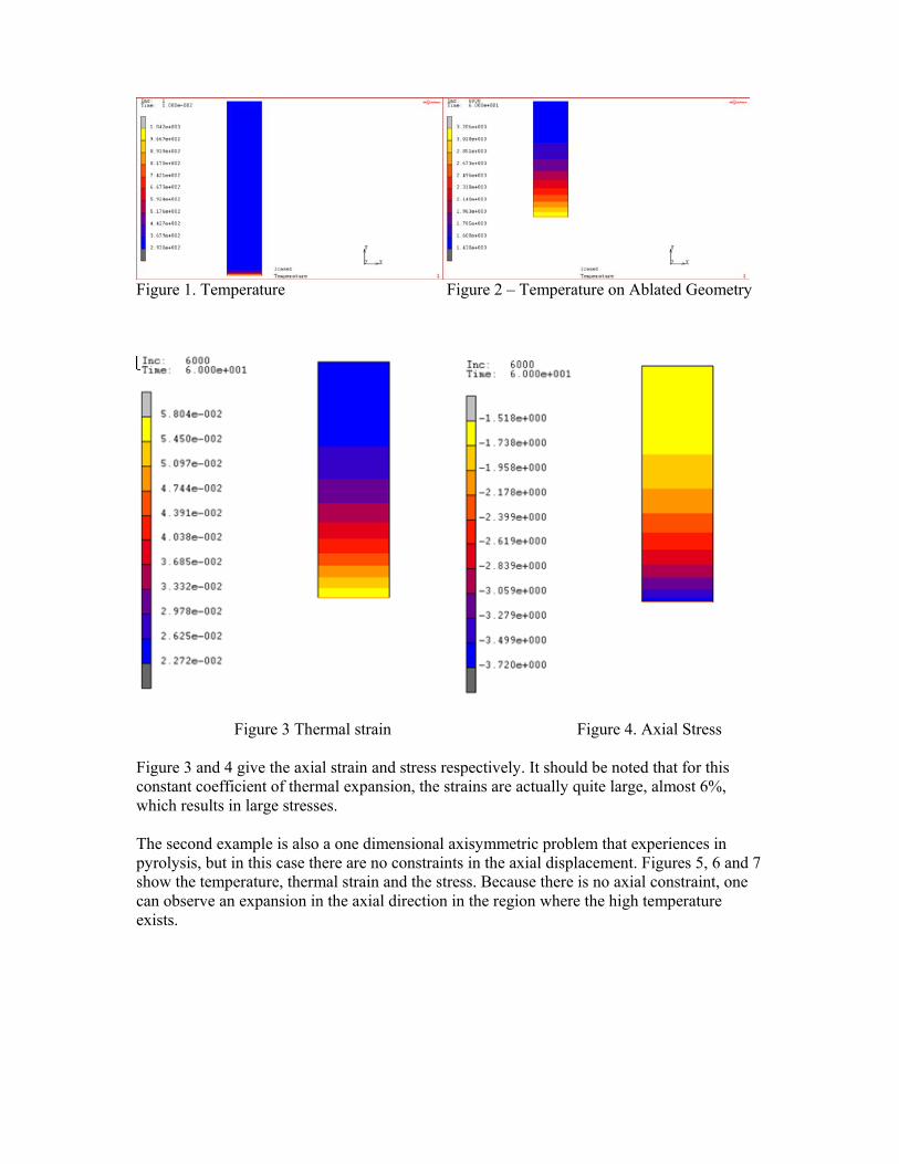
Figure 1. Temperature Figure 2 – Temperature on Ablated Geometry
Figure 3 Thermal strain Figure 4. Axial Stress Figure 3 and 4 give the axial strain and stress respectively. It should be noted that for this constant coefficient of thermal expansion, the strains are actually quite large, almost 6%, which results in large stresses. The second example is also a one dimensional axisymmetric problem that experiences in pyrolysis, but in this case there are no constraints in the axial displacement. Figures 5, 6 and 7 show the temperature, thermal strain and the stress. Because there is no axial constraint, one can observe an expansion in the axial direction in the region where the high temperature exists.
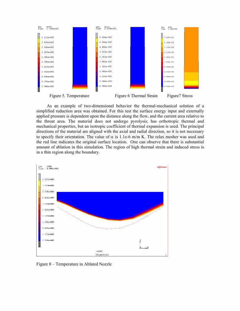
Figure 5. Temperature Figure 6 Thermal Strain Figure7 Stress
As an example of two-dimensional behavior the thermal-mechanical solution of a simplified reduction area was obtained. For this test the surface energy input and externally applied pressure is dependent upon the distance along the flow, and the current area relative to the throat area. The material does not undergo pyrolysis; has orthotropic thermal and mechanical properties, but an isotropic coefficient of thermal expansion is used. The principal directions of the material are aligned with the axial and radial direction, so it is not necessary to specify their orientation. The value of α is 1.1e-6 m/m K. The relax mesher was used and the red line indicates the original surface location. One can observe that there is substantial amount of ablation in this simulation. The region of high thermal strain and induced stress is in a thin region along the boundary.
Figure 8 – Temperature in Ablated Nozzle

Figure 9 – Thermal Strains in Nozzle
Figure 10 – Mechanical stresses in Nozzle Figure 11 shows the direction of the externally applied forces. In all of these simulations the Follower Force option is activated such that the pressures are applied to the updated geometry. In the case of the previous 1-d problems, the external force is increasing because the pressure was held constant, while the internal radius increased. In the simulation of the nozzle there is the interaction of the pressure decreasing due to aerodynamic effects because the throat radius is increasing while the resultant force increased because the radius is increasing.
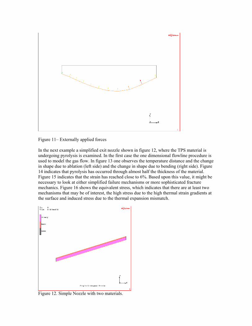
Figure 11– Externally applied forces In the next example a simplified exit nozzle shown in figure 12, where the TPS material is undergoing pyrolysis is examined. In the first case the one dimensional flowline procedure is used to model the gas flow. In figure 13 one observes the temperature distance and the change in shape due to ablation (left side) and the change in shape due to bending (right side). Figure 14 indicates that pyrolysis has occurred through almost half the thickness of the material. Figure 15 indicates that the strain has reached close to 6%. Based upon this value, it might be necessary to look at either simplified failure mechanisms or more sophisticated fracture mechanics. Figure 16 shows the equivalent stress, which indicates that there are at least two mechanisms that may be of interest, the high stress due to the high thermal strain gradients at the surface and induced stress due to the thermal expansion mismatch.
Figure 12. Simple Nozzle with two materials.
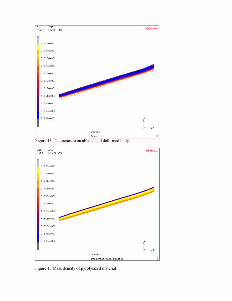
Figure 13. Temperature on ablated and deformed body.
Figure 13 Mass density of pyrolysized material

Figure 14 Principal thermal strains.
Figure 15 Equivalent stress – stresses are in GPa. This simplified nozzle was also analyzed using the second method, where Darcy’s law is used to model the flow of the pyrolysis gas. In this test ablation was eliminated from the analysis. The porosity of the material decreases by an order of magnitude in the pyrolsized zone as
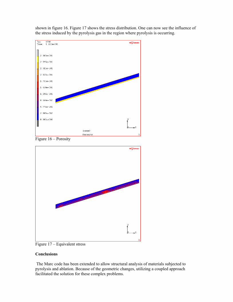
shown in figure 16. Figure 17 shows the stress distribution. One can now see the influence of the stress induced by the pyrolysis gas in the region where pyrolysis is occurring.
Figure 16 – Porosity
Figure 17 – Equivalent stress Conclusions The Marc code has been extended to allow structural analysis of materials subjected to pyrolysis and ablation. Because of the geometric changes, utilizing a coupled approach facilitated the solution for these complex problems.
References [1] H.L.N. Mc Manus, G.S. Springer High temperature thermomechanical behavior of carbon-phenolic and carbon- carbon composites, I. Analysis.J. Composite Materials, Vol. 26, No. 2, pp. 207-229, 1992.
[2] Y. Wu, N. Katsube Balance laws for decomposing carbon-phenolic composites with moisture. AIAA Paper 94-1581, AIAA/ASME/ASCE/AHS/ASC 35th Structures, Structural Dynamics and Materials Conference, 1994.
[3] C.B. Moyer, R.A. Rindal An analysis of the coupled chemically reacting boundary layer and charring ablator. Part II. Finite difference solution for the in-depth response of charring materials considering surface chemical and energy balances.NASA CR-1061, June 1968.
[4] A.D. Baer, J.H. Hedges, J.D. Seader, K.M. Jayakar, L.H. Wojcik Polymer pyrolysis over a wide range of heating rates. AIAA J., Vol. 15, No. 10, pp. 1398-1404, October 1977.
[5] K.A. Trick, T.E. Saliba, S.S. Sandhu A kinetic model of the pyrolysis of phenolic resin in a carbon / phenolic composite. Carbon, Vol. 35, No. 3, pp. 393-401, 1997.
[6] B. Laub The Apollo heatshield. Why performance exceeded expectations. Int. Symposium Atmospheric Reentry Vehicles and Systems, Arcachon, March 16-18, 1999.
[7] R.M. Kendall, R.A. Rindal, E.P. Bartlett A multicomponent boundary layer chemically coupled to an ablating surface. AIAA J., Vol. 5, No. 6, pp. 1063-1071, June 1967.
[8] J.W. Schaefer, H. Tong, R.J. Bedard Kinetic reaction rates for consumption of pyrolytic graphite. AIAA Paper 74-1056, AIAA/SAE 10th Propulsion Conference, San Diego, October 21-23, 1974.
[9] K.K. Kuo, S.T. Keswani A comprehensive theoretical model for carbon/carbon composite nozzle recession. Combustion Science and Technology, Vol. 42, pp. 145-164, 1985.
[10] G.B. Spear The role of chemical reactions and mechanical erosion in aerothermal modeling of external insulations. AIAA Paper 90-1868, AIAA/SAE/ASME/ASEE 26th Joint Propulsion Conference, Orlando, July 16-18, 1990.
[11] B.C. Yang, F.B. Cheung, J.H. Koo Numerical investigation of thermo-chemical and mechanical erosion of ablative materials. AIAA Paper 93-2045, AIAA/SAE/ASME/ASEE 29th Joint Propulsion Conference and Exhibit, Monterey, June 28-30, 1993.
[12] B. Laub, R.A.S. Beck Characterization and modeling of low density TPS materials for recovery vehicles. SAE Technical Paper Series 941368, 24th International Conference on Environmental Systems and 5th European Symposium on Space Environmental Control Systems, Friedrichshafen, June 20-23, 1994.
[13] F.S. Milos, Y.K. Chen Comprehensive model for multicomponent ablation thermochemistry. AIAA Paper 97-0141, AIAA 35th Aerospace Science Meeting & Exhibit, Reno, January 6-9, 1997. Ablation des protections thermiques internes dans les propulseurs à propergol solide. Colloque Ecoulements Propulsifs dans les Systèmes de Transport Spatial, Bordeaux, 11-15 septembre 1995.