Embed Size (px)
Citation preview
Chapter 48
Thermal Effects on Shear Fracturing and InjectivityDuring CO2 Storage
Somayeh Goodarzi, Antonin Settari,Mark Zoback and David W. Keith
Additional information is available at the end of the chapter
http://dx.doi.org/10.5772/56311
Abstract
With almost two hundred coal burning power plants in Ohio River valley, this region isconsidered important for evaluation of CO2 storage potential. In a CO2 storage project, thetemperature of the injected CO2 is usually considerably lower than the formation temperature.The heat transfer between the injected fluid and rock has to be investigated in order to test theviability of the target formation to act as an effective storage unit and to optimize the storageprocess. In our previous work we have introduced the controversial idea of injecting CO2 forstorage at fracturing conditions in order to improve injectivity and economics. Here weexamine the thermal aspects of such process in a setting typical for Ohio River Valley targetformation.
A coupled flow, geomechanical and heat transfer model for the potential injection zone andsurrounding formations has been developed. All the modeling focuses on a single wellperformance and considers induced fracturing for both isothermal and thermal injectionconditions. The induced thermal effects of CO2 injection on stresses, and fracture pressure, andpropagation are investigated. Possibility of shear failure in the caprock resulting from heattransfer between reservoir and the overburden layers is also examined.
In the thermal case, the total minimum stress at the wellbore decreases with time and fallsbelow the injection pressure quite early during injection. Therefore, fracturing occurs atconsiderably lower pressure, when thermal effects are present. The coupled thermal anddynamic fracture model shows that these effects could increase the speed of fracture propa‐gation in the storage layer depending on the injection rate. These phenomena are dependentprimarily on the difference between the injection and reservoir temperature.
© 2013 Goodarzi et al.; licensee InTech. This is an open access article distributed under the terms of theCreative Commons Attribution License (http://creativecommons.org/licenses/by/3.0), which permitsunrestricted use, distribution, and reproduction in any medium, provided the original work is properly cited.
Our results show that shortly after injection, the induced expansion in caprock lead to slightincrease of total stresses (poroelasticity) which will reduce the chance of shear failure. Howeveras soon as total minimum stress in the caprock decreases due to thermal diffusion between thereservoir and caprock, thermoelasticity dominates and the chance of shear failure increases inthe caprock.
Incorporation of thermal effects in modeling of CO2 injection is significant for understandingthe dynamics of induced fracturing in storage operations. Our work shows that the injectioncapacity with cold CO2 injection could be significantly lower than expected, and it may beimpractical to avoid induced fracture development. In risk assessment studies inclusion of thethermal effects will help prevent the unexpected leakage in storage projects.
1. Introduction
Past storage pilot projects and enhanced oil recovery efforts have shown that, geologicsequestration of CO2 is a technically viable means of reducing anthropogenic emission ofCO2 from accumulating in the atmosphere [1,2,3]. Security of storage is one of the mostimportant concerns with the long term injection of CO2 in underground formations. Injectionof CO2 induces stress and pore pressure changes which could eventually lead to the formationor reactivation of fracture networks and/or shear failure which could potentially providepathways for CO2 leakage through previously impermeable rocks [4]. Therefore geomechan‐ical modeling plays a very important role in risk assessment of geological storage of CO2.
In order to determine whether the induced stress changes compromises the ability of theformation to act as an effective storage unit, a geomechanical assessment of the formationintegrity must be carried out. In our previous work, we have studied the dynamic propagationof fracture in the Rose Run sandstone reservoir in Ohio River valley under isothermal [5] andthermal condition [6] for injection above fracture pressure. In this paper, the thermal effect ofinjection on the possibility of tensile and shear failure in the reservoir and caprock are studiedfor injection below fracture pressure. This study utilized a fully coupled reservoir flow andgeomechanical model which allows accounting for poroelastic and thermoelastic effects andcan model static and/or dynamic fractures.
To examine the possibility of shear failure in the caprock, Mohr-Coloumb Criteria was used.
2. Construction of the flow, thermal and geomechanical model
A coupled flow, thermal, and geomechanical model has been developed in order to study thethermo-elastic and poro-elastic response of the injection and surrounding layer to increasingof pressure and reduction of temperature after CO2 injection. Ohio River valley is located in arelatively stable, intraplate tectonic setting and the regional stress state is in strike slip faultingregime with the maximum stress oriented northeast to east-northeast [7].
Effective and Sustainable Hydraulic Fracturing946
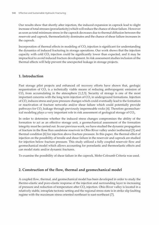
This study used the fluid and rock mechanical properties provided by Lucier et al. [8]. Thestratigraphic sequence of the geological layers in the study area and the relative location of thepotential injection layer, Rose Run Sandstone (RRS) at the Mountaineer site is shown in Figure1. RRS has an average thickness of 30 m and is extended from 2355-2385 m. The direction ofmaximum and minimum horizontal stresses is reported to be in N47E(±13) and N43W (±13)respectively [8]. All the models in this study are aligned along these directions, in order toavoid having initial non-zero value of shear stresses in principal stress directions.
Figure 1. Generalized stratigraphy of the study area at the Mountaineer site. The well location and the general stratig‐raphy intersected by well is illustrated in the picture. The black box shows the boundaries of the area of previous workby Lucier et al., [8], Modified from [9]
Thermal Effects on Shear Fracturing and Injectivity During CO2 Storagehttp://dx.doi.org/10.5772/56311
947
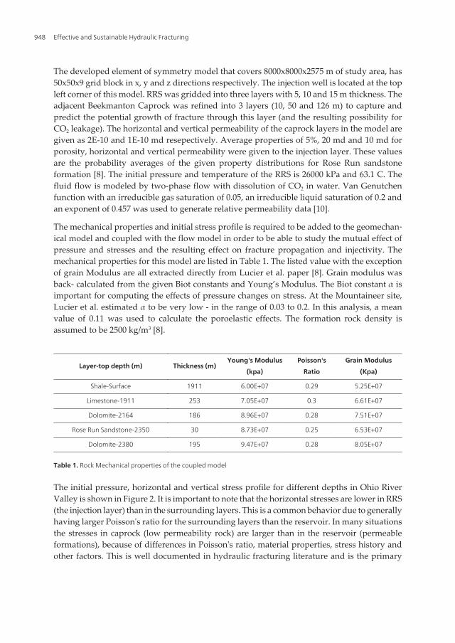
The developed element of symmetry model that covers 8000x8000x2575 m of study area, has50x50x9 grid block in x, y and z directions respectively. The injection well is located at the topleft corner of this model. RRS was gridded into three layers with 5, 10 and 15 m thickness. Theadjacent Beekmanton Caprock was refined into 3 layers (10, 50 and 126 m) to capture andpredict the potential growth of fracture through this layer (and the resulting possibility forCO2 leakage). The horizontal and vertical permeability of the caprock layers in the model aregiven as 2E-10 and 1E-10 md resepectively. Average properties of 5%, 20 md and 10 md forporosity, horizontal and vertical permeability were given to the injection layer. These valuesare the probability averages of the given property distributions for Rose Run sandstoneformation [8]. The initial pressure and temperature of the RRS is 26000 kPa and 63.1 C. Thefluid flow is modeled by two-phase flow with dissolution of CO2 in water. Van Genutchenfunction with an irreducible gas saturation of 0.05, an irreducible liquid saturation of 0.2 andan exponent of 0.457 was used to generate relative permeability data [10].
The mechanical properties and initial stress profile is required to be added to the geomechan‐ical model and coupled with the flow model in order to be able to study the mutual effect ofpressure and stresses and the resulting effect on fracture propagation and injectivity. Themechanical properties for this model are listed in Table 1. The listed value with the exceptionof grain Modulus are all extracted directly from Lucier et al. paper [8]. Grain modulus wasback- calculated from the given Biot constants and Young’s Modulus. The Biot constant α isimportant for computing the effects of pressure changes on stress. At the Mountaineer site,Lucier et al. estimated α to be very low - in the range of 0.03 to 0.2. In this analysis, a meanvalue of 0.11 was used to calculate the poroelastic effects. The formation rock density isassumed to be 2500 kg/m3 [8].
Layer-top depth (m) Thickness (m)Young's Modulus
(kpa)
Poisson's
Ratio
Grain Modulus
(Kpa)
Shale-Surface 1911 6.00E+07 0.29 5.25E+07
Limestone-1911 253 7.05E+07 0.3 6.61E+07
Dolomite-2164 186 8.96E+07 0.28 7.51E+07
Rose Run Sandstone-2350 30 8.73E+07 0.25 6.53E+07
Dolomite-2380 195 9.47E+07 0.28 8.05E+07
Table 1. Rock Mechanical properties of the coupled model
The initial pressure, horizontal and vertical stress profile for different depths in Ohio RiverValley is shown in Figure 2. It is important to note that the horizontal stresses are lower in RRS(the injection layer) than in the surrounding layers. This is a common behavior due to generallyhaving larger Poisson's ratio for the surrounding layers than the reservoir. In many situationsthe stresses in caprock (low permeability rock) are larger than in the reservoir (permeableformations), because of differences in Poisson's ratio, material properties, stress history andother factors. This is well documented in hydraulic fracturing literature and is the primary
Effective and Sustainable Hydraulic Fracturing948
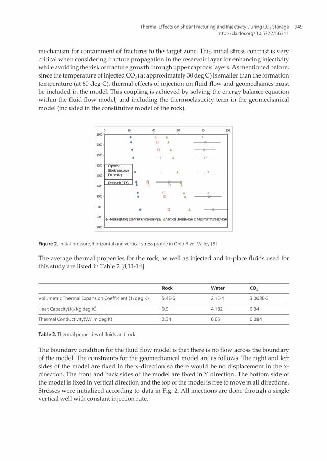
mechanism for containment of fractures to the target zone. This initial stress contrast is verycritical when considering fracture propagation in the reservoir layer for enhancing injectivitywhile avoiding the risk of fracture growth through upper caprock layers. As mentioned before,since the temperature of injected CO2 (at approximately 30 deg C) is smaller than the formationtemperature (at 60 deg C), thermal effects of injection on fluid flow and geomechanics mustbe included in the model. This coupling is achieved by solving the energy balance equationwithin the fluid flow model, and including the thermoelasticity term in the geomechanicalmodel (included in the constitutive model of the rock).
1900
2000
2100
2200
2300
2400
2500
2600
2700
2800
0 20 40 60 80 100
Pressure(Mpa) Minimum Stress(Mpa) Vertical Stress(Mpa) Maximum Stress(Mpa)
Caprock (BeekmantownDolomite)
Reservoir (RRS)
Figure 2. Initial pressure, horizontal and vertical stress profile in Ohio River Valley [8]
The average thermal properties for the rock, as well as injected and in-place fluids used forthis study are listed in Table 2 [8,11-14].
Rock Water CO2
Volumetric Thermal Expansion Coefficient (1/deg K) 5.4E-6 2.1E-4 3.003E-3
Heat Capacity(Kj/Kg deg K) 0.9 4.182 0.84
Thermal Conductivity(W/ m deg K) 2.34 0.65 0.084
Table 2. Thermal properties of fluids and rock
The boundary condition for the fluid flow model is that there is no flow across the boundaryof the model. The constraints for the geomechanical model are as follows. The right and leftsides of the model are fixed in the x-direction so there would be no displacement in the x-direction. The front and back sides of the model are fixed in Y direction. The bottom side ofthe model is fixed in vertical direction and the top of the model is free to move in all directions.Stresses were initialized according to data in Fig. 2. All injections are done through a singlevertical well with constant injection rate.
Thermal Effects on Shear Fracturing and Injectivity During CO2 Storagehttp://dx.doi.org/10.5772/56311
949
3. Thermal fracturing in the reservoir below isothermal fracture pressure
Thermal effects of CO2 injection is expected to affect the magnitude of displacements, pressure,stresses, and the possibility of shear and tensile failure in the reservoir and caprock. Injectingfluid with temperature lower than reservoir rock temperature will cause reduction of stressesin the injection layer and once the temperature front has reached a relatively large area aroundthe wellbore, this reduction in stresses will result in negative volumetric strains that canpropagate to the surface. Therefore the surface displacement for the thermal model would besmaller than that of isothermal model [6].
One of the most important effects of injecting a fluid with a lower than reservoir temperatureis the reduction of fracture pressure. Cooling of the formation rock during injection of coldCO2 through thermal conduction and convection lowers the total stresses in the reservoir andpossibly caprock layer. This results in reduction of fracture pressure and the pressure differ‐ential available for injection, and therefore injectivity. In the case of injection at fracturingconditions, the fracture propagation pressure will decrease and, if the same injection rate isused, this will accelerate fracture propagation.
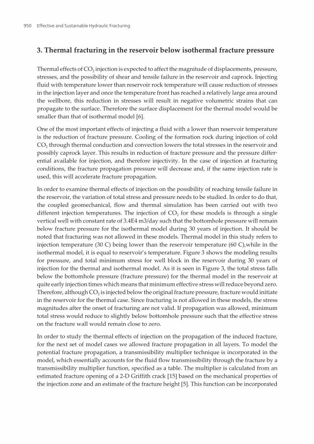
In order to examine thermal effects of injection on the possibility of reaching tensile failure inthe reservoir, the variation of total stress and pressure needs to be studied. In order to do that,the coupled geomechanical, flow and thermal simulation has been carried out with twodifferent injection temperatures. The injection of CO2 for these models is through a singlevertical well with constant rate of 3.4E4 m3/day such that the bottomhole pressure will remainbelow fracture pressure for the isothermal model during 30 years of injection. It should benoted that fracturing was not allowed in these models. Thermal model in this study refers toinjection temperature (30 C) being lower than the reservoir temperature (60 C),while in theisothermal model, it is equal to reservoir’s temperature. Figure 3 shows the modeling resultsfor pressure, and total minimum stress for well block in the reservoir during 30 years ofinjection for the thermal and isothermal model. As it is seen in Figure 3, the total stress fallsbelow the bottomhole pressure (fracture pressure) for the thermal model in the reservoir atquite early injection times which means that minimum effective stress will reduce beyond zero.Therefore, although CO2 is injected below the original fracture pressure, fracture would initiatein the reservoir for the thermal case. Since fracturing is not allowed in these models, the stressmagnitudes after the onset of fracturing are not valid. If propagation was allowed, minimumtotal stress would reduce to slightly below bottomhole pressure such that the effective stresson the fracture wall would remain close to zero.
In order to study the thermal effects of injection on the propagation of the induced fracture,for the next set of model cases we allowed fracture propagation in all layers. To model thepotential fracture propagation, a transmissibility multiplier technique is incorporated in themodel, which essentially accounts for the fluid flow transmissibility through the fracture by atransmissibility multiplier function, specified as a table. The multiplier is calculated from anestimated fracture opening of a 2-D Griffith crack [15] based on the mechanical properties ofthe injection zone and an estimate of the fracture height [5]. This function can be incorporated
Effective and Sustainable Hydraulic Fracturing950
in the model both as a function of pressure or effective minimum stress. The actual fracturegeometry can be calculated by the coupled model.
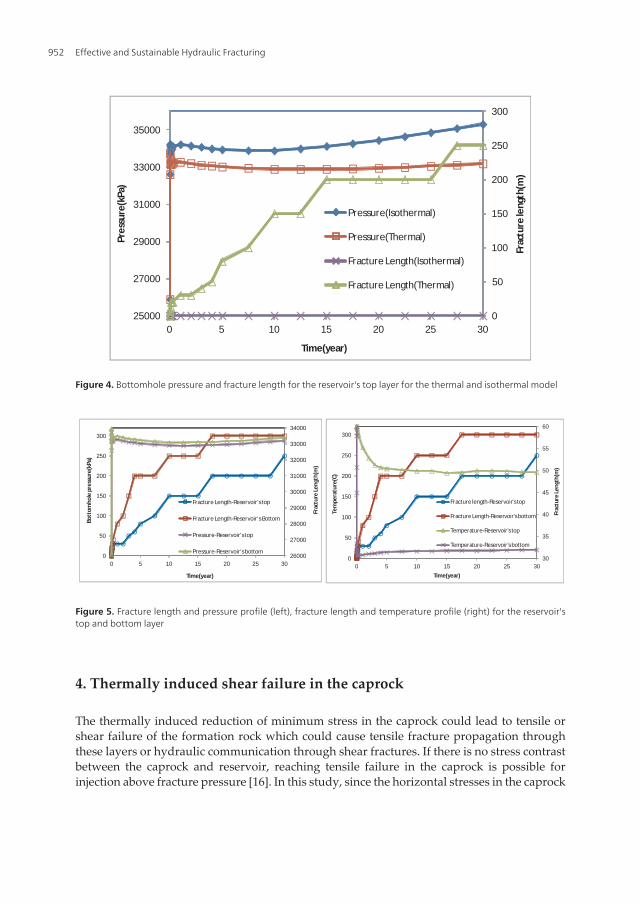
Figure 4 shows the bottomhole pressure and fracture length for the reservoir's top layer forthe thermal and isothermal model. As expected, since the bottomhole pressure remains belowthe fracture pressure for the isothermal model, there is no fracture initiation in the reservoirfor the isothermal model. However since minimum effective stress reduces beyond zero in thethermal model (thermoelastic effects), fracture initiates and propagates through reservoir to ahalf length of 250 m. The bottomhole pressure in the thermal model is now significantlydifferent. For the thermal model, it increases to fracture initiation pressure (equal to thethermally reduced minimum total stress) and then remains almost constant for the injectionperiod. However for the isothermal model, the pressure history is the same as in Fig. 4.
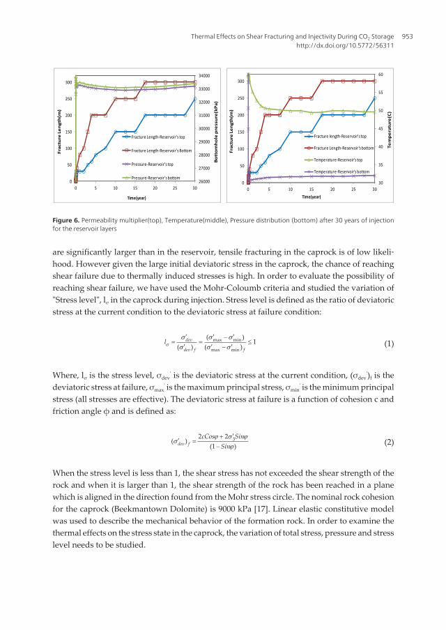
Figure 5 shows the fracture length, pressure and temperature profile for the well block in thereservoir's top and bottom layer. The results show that under thermal conditions, fracturepropagates to a larger extent in the lower reservoir layers than the top ones. As seen in theFigure, the pressures in the reservoir's top and bottom layers are very close. However, thetemperature in the bottom of the reservoir is significantly lower than in the top. This resultsin higher reduction of minimum total stress and lower fracture pressure for the reservoir'sbottom layer. This effect can also be clearly seen in Figure 6 which shows the permeabilitymultiplier, temperature and pressure profile in fracture plane near the wellbore (zoomed to300 m) across reservoir layers. As seen the temperature reduction and permeability multipliersare higher in the bottom layer.
19000
21000
23000
25000
27000
29000
31000
33000
35000
37000
0 5 10 15 20 25 30
Pres
sure
,Min
imum
str
ess(
kPa)
Time(yr)
Pressure (Isothermal)
Pressure (Thermal)
Minimum Stress (Isothermal)
Minimum stress (Thermal)
Figure 3. Pressure, minimum stress, and stress level for the thermal and isothermal model for the well block in thereservoir's top layer
Thermal Effects on Shear Fracturing and Injectivity During CO2 Storagehttp://dx.doi.org/10.5772/56311
951
30
35
40
45
50
55
60
0
50
100
150
200
250
300
0 5 10 15 20 25 30
Frac
ture
Len
gth(
m)
Tem
pera
ture
(C)
Time(year)
Fracture length-Reservoir's top
Fracture Length-Reservoir's bottom
Temperature-Reservoir's top
Temperature-Reservoir's bottom
26000
27000
28000
29000
30000
31000
32000
33000
34000
0
50
100
150
200
250
300
0 5 10 15 20 25 30
Frac
ture
Len
gth(
m)
Bott
omho
le p
ress
ure(
kPa)
Time(year)
Fracture Length-Reservoir's top
Fracture Length-Reservoir's Bottom
Pressure-Reservoir's top
Pressure-Reservoir's bottom
Figure 5. Fracture length and pressure profile (left), fracture length and temperature profile (right) for the reservoir'stop and bottom layer
4. Thermally induced shear failure in the caprock
The thermally induced reduction of minimum stress in the caprock could lead to tensile orshear failure of the formation rock which could cause tensile fracture propagation throughthese layers or hydraulic communication through shear fractures. If there is no stress contrastbetween the caprock and reservoir, reaching tensile failure in the caprock is possible forinjection above fracture pressure [16]. In this study, since the horizontal stresses in the caprock
0
50
100
150
200
250
300
25000
27000
29000
31000
33000
35000
0 5 10 15 20 25 30
Frac
ture
leng
th(m
)
Pres
sure
(kPa
)
Time(year)
Pressure(Isothermal)
Pressure(Thermal)
Fracture Length(Isothermal)
Fracture Length(Thermal)
Figure 4. Bottomhole pressure and fracture length for the reservoir's top layer for the thermal and isothermal model
Effective and Sustainable Hydraulic Fracturing952
are significantly larger than in the reservoir, tensile fracturing in the caprock is of low likeli‐hood. However given the large initial deviatoric stress in the caprock, the chance of reachingshear failure due to thermally induced stresses is high. In order to evaluate the possibility ofreaching shear failure, we have used the Mohr-Coloumb criteria and studied the variation of"Stress level", lσ in the caprock during injection. Stress level is defined as the ratio of deviatoricstress at the current condition to the deviatoric stress at failure condition:
max min
max min
( )1
( ) ( )dev
dev f fls
s s ss s s¢ ¢ ¢-
= = £¢ ¢ ¢- (1)
Where, lσ is the stress level, σdev' is the deviatoric stress at the current condition, (σdev
')f is thedeviatoric stress at failure, σmax
' is the maximum principal stress, σmin' is the minimum principal
stress (all stresses are effective). The deviatoric stress at failure is a function of cohesion c andfriction angle ϕ and is defined as:
32 2( )
(1 )dev fcCos Sin
Sinj s j
sj¢+
¢ =- (2)
When the stress level is less than 1, the shear stress has not exceeded the shear strength of therock and when it is larger than 1, the shear strength of the rock has been reached in a planewhich is aligned in the direction found from the Mohr stress circle. The nominal rock cohesionfor the caprock (Beekmantown Dolomite) is 9000 kPa [17]. Linear elastic constitutive modelwas used to describe the mechanical behavior of the formation rock. In order to examine thethermal effects on the stress state in the caprock, the variation of total stress, pressure and stresslevel needs to be studied.
Figure 6: Fracture length and pressure profile (left), fracture length and temperature profile (right) for the reservoir's top and bottom layer
26000
27000
28000
29000
30000
31000
32000
33000
34000
0
50
100
150
200
250
300
0 5 10 15 20 25 30
Bottomhole pressure(kPa)
Fracture Length(m
)
Time(year)
Fracture Length‐Reservoir's top
Fracture Length‐Reservoir's Bottom
Pressure‐Reservoir's top
Pressure‐Reservoir's bottom30
35
40
45
50
55
60
0
50
100
150
200
250
300
0 5 10 15 20 25 30
Temperature(C)
Fracture Length(m
)
Time(year)
Fracture length‐Reservoir's top
Fracture Length‐Reservoir's bottom
Temperature‐Reservoir's top
Temperature‐Reservoir's bottom
Figure 6. Permeability multiplier(top), Temperature(middle), Pressure distribution (bottom) after 30 years of injectionfor the reservoir layers
Thermal Effects on Shear Fracturing and Injectivity During CO2 Storagehttp://dx.doi.org/10.5772/56311
953
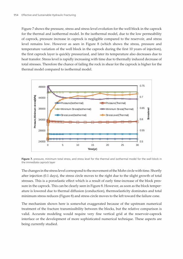
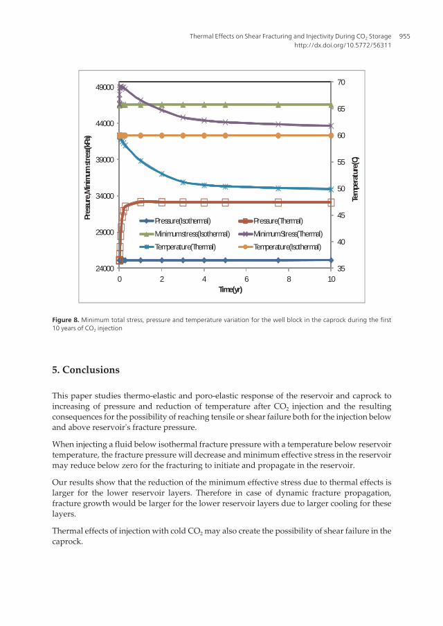
Figure 7 shows the pressure, stress and stress level evolution for the well block in the caprockfor the thermal and isothermal model. In the isothermal model, due to the low permeabilityof caprock, pressure increase in caprock is negligible compared to the reservoir, and stresslevel remains low. However as seen in Figure 8 (which shows the stress, pressure andtemperature variation of the well block in the caprock during the first 10 years of injection),the first caprock layer is quickly pressurized, and later its temperature also decreases due toheat transfer. Stress level is rapidly increasing with time due to thermally induced decrease oftotal stresses. Therefore the chance of failing the rock in shear for the caprock is higher for thethermal model compared to isothermal model.
0.5
0.55
0.6
0.65
0.7
0.75
24000
29000
34000
39000
44000
49000
0 5 10 15 20 25 30St
ress
leve
l
Pres
sure
,Min
imum
str
ess(
kPa)
Time(yr)
Pressure(Isothermal) Pressure(Thermal)
Minimum Stress(Isothermal) Minimum Stress(Thermal)
Stress Level(Isothermal) Stress Level(Thermal)
Figure 7. pressure, minimum total stress, and stress level for the thermal and isothermal model for the well block inthe immediate caprock layer
The changes in the stress level correspond to the movement of the Mohr circle with time. Shortlyafter injection (0.1 days), the stress circle moves to the right due to the slight growth of totalstresses. This is a poroelastic effect which is a result of early time-increase of the block pres‐sure in the caprock. This can be clearly seen in Figure 8. However, as soon as the block temper‐ature is lowered due to thermal diffusion (conduction), thermoelasticity dominates and totalminimum stress reduces (Figure 8) and stress circle moves to the left toward the failure cone.
The mechanism shown here is somewhat exaggerated because of the upstream numericaltreatment of the fracture transmissibility between the blocks, but the relative comparison isvalid. Accurate modeling would require very fine vertical grid at the reservoir-caprockinterface or the development of more sophisticated numerical technique. These aspects arebeing currently studied.
Effective and Sustainable Hydraulic Fracturing954
35
40
45
50
55
60
65
70
24000
29000
34000
39000
44000
49000
0 2 4 6 8 10
Tem
pera
ture
(C)
Pres
sure
,Min
imum
stre
ss(k
Pa)
Time(yr)
Pressure(Isothermal) Pressure(Thermal)
Minimum stress(Isothermal) Minimum Stress(Thermal)
Temperature(Thermal) Temperature(Isothermal)
Figure 8. Minimum total stress, pressure and temperature variation for the well block in the caprock during the first10 years of CO2 injection
5. Conclusions
This paper studies thermo-elastic and poro-elastic response of the reservoir and caprock toincreasing of pressure and reduction of temperature after CO2 injection and the resultingconsequences for the possibility of reaching tensile or shear failure both for the injection belowand above reservoir's fracture pressure.
When injecting a fluid below isothermal fracture pressure with a temperature below reservoirtemperature, the fracture pressure will decrease and minimum effective stress in the reservoirmay reduce below zero for the fracturing to initiate and propagate in the reservoir.
Our results show that the reduction of the minimum effective stress due to thermal effects islarger for the lower reservoir layers. Therefore in case of dynamic fracture propagation,fracture growth would be larger for the lower reservoir layers due to larger cooling for theselayers.
Thermal effects of injection with cold CO2 may also create the possibility of shear failure in thecaprock.
Thermal Effects on Shear Fracturing and Injectivity During CO2 Storagehttp://dx.doi.org/10.5772/56311
955
Author details
Somayeh Goodarzi1*, Antonin Settari1, Mark Zoback2 and David W. Keith3
*Address all correspondence to: [email protected]
1 University of Calgary, Calgary, Canada
2 Stanford University, USA
3 Harvard University, USA
References
[1] Solomon, S. Carbon Dioxide Storage: Geological Security and Environmental Issues-Case Study on the Sleipner Gas Field in Norway. The Bellona Foundation. (2006).
[2] Preston, C, Monea, M, et al. IEA GHG Weyburn CO2 Monitoring and Storage Project,Fuel Processing Technology. (2005). , 86, 1547-1568.
[3] Wright, L. W. (2007). The In Salah Gas CO2 Storage Project. International PetroleumTechnology Conference
[4] QuintessaNational Institute of Advanced Industrial Science and Technology of Ja‐pan, Quintessa Japan, JGC Corporation, Mizuho Information and Research Institute.(2007). Building Confidence in Geological Storage of Carbon Dioxide. Ministry ofEconomy, Trade and Industry (METI), IEA Greenhouse Gas R&D Programme (IEAGHG).
[5] Goodarzi, S, Settari, A, Zoback, M, & Keith, D. A Coupled Geomechanical ReservoirSimulation analysis of CO2 storage in a Saline Aquifer in the Ohio River Valley.(2011). Environmental Geosciences journal. American Association of Petroleum Geol‐ogists. , 18(3), 1-20.
[6] Goodarzi, S, Settari, A, Zoback, M, & Keith, D. Thermal Aspects of Geomechanicsand Induced Fracturing in CO2 Injection With Application to CO2 Sequestration inOhio River Valley. SPE-PP, SPE International Conference on CO2 Capture, Storage,and Utilization held in New Orleans, Louisiana, USA, 10-12 November (2010). ,139706.
[7] Zoback, M. D, & Zoback, M. L. State of stress and intraplate earthquakes in the cen‐tral and eastern United States. Science, (1981). , 213, 96-109.
[8] Lucier, A, Zoback, M, Gupta, N, & Ramakrishnan, T. S. (2006). Geomechanical as‐pects of CO2 sequestration in a deep saline reservoir in the Ohio River Valley region.Environmental Geosciences 13 (2), 85-103.
Effective and Sustainable Hydraulic Fracturing956
[9] Gupta, N. (2008). The Ohio river valley CO2 storage project, Final Technical Report,prepared for US Department of Energy-National Energy Technology Laboratory
[10] Van Genuchten, M. T. equation for predicting the hydraulic conductivity of unsatu‐rated soils: Soil Science Society of America Journal, , 44, 892-898.
[11] Collieu, A. McB., Powney, D. J., Girifalco, L. A. et al., (1975). The Mechanical andThermal Properties of Materials and Statistical Physics of Materials. Phys. Today 28,51
[12] Fjaer, E, Holt, R. M, Horsrud, P, et al. (2008). Petroleum Related Rock Mechanics. 441.Elsevier.
[13] Guildner, L. A. (1958). The thermal conductivity of carbon dioxide in the region ofthe critical point, Proceedings of the National Academy of Sciences of the UnitedStates of America, , 44(11), 1149-1153.
[14] Yaws, C. (2008). Thermophysical properties of chemicals and hydrocarbons. 793. Wil‐liam Andrew Publishing
[15] Sneddon, I. N, & Lowengrub, M. Crack Problems in the Classical Theory of Elastici‐ty, John Wiley & Sons Inc., New York, (1969). , 19.
[16] Goodarzi, S, Settari, A, & Keith, D. (2012). Geomechanical modeling for CO2 storagein Nisku aquifer in Wabamun lake area in Canada. International Journal of Green‐house Gas Control , 10, 113-122.
[17] Maurer, W. C. (1965). Bit-Tooth Penetration under Simulated Borehole Conditions,Petroleum Transactions
Thermal Effects on Shear Fracturing and Injectivity During CO2 Storagehttp://dx.doi.org/10.5772/56311
957


![arXiv:math/0612069v1 [math.DG] 3 Dec 2006bounded injectivity radii at the marked points. By imposing an injectivity radius condition, he rescaled the solution to show that each singularity](https://img.pdfslide.us/doc/110x75/612080ace3a1697fdf4b1ba4/arxivmath0612069v1-mathdg-3-dec-bounded-injectivity-radii-at-the-marked-points.jpg)