Embed Size (px)
Citation preview
Contents lists available at ScienceDirect
Journal of the Mechanics and Physics of Solids
Journal of the Mechanics and Physics of Solids 64 (2014) 223–235
0022-50http://d
n CorrE-m
journal homepage: www.elsevier.com/locate/jmps
Impact comminution of solids due to local kinetic energyof high shear strain rate: I. Continuum theory andturbulence analogy
Zdeněk P. Bažant a,n, Ferhun C. Caner b
a Northwestern University, 2145 Sheridan Road, CEE/A135, Evanston, IL 60208, United Statesb Institute of Energy Technologies, Technical University of Catalonia, Av. Diagonal 647, 08028 Barcelona, Spain
a r t i c l e i n f o
Article history:Received 21 July 2013Received in revised form11 November 2013Accepted 13 November 2013Available online 25 November 2013
Keywords:Fracture mechanicsDynamic fractureFragmentationEffective viscosityPenetration
96/$ - see front matter & 2013 Elsevier Ltd.x.doi.org/10.1016/j.jmps.2013.11.008
esponding author. Tel.: þ1 847 491 4025; faail addresses: [email protected] (Z
a b s t r a c t
The modeling of high velocity impact into brittle or quasibrittle solids is hampered by theunavailability of a constitutive model capturing the effects of material comminution intovery fine particles. The present objective is to develop such a model, usable in finiteelement programs. The comminution at very high strain rates can dissipate a large portionof the kinetic energy of an impacting missile. The spatial derivative of the energydissipated by comminution gives a force resisting the penetration, which is superposedon the nodal forces obtained from the static constitutive model in a finite elementprogram. The present theory is inspired partly by Grady's model for expansive comminu-tion due to explosion inside a hollow sphere, and partly by analogy with turbulence. Inhigh velocity turbulent flow, the energy dissipation rate gets enhanced by the formationof micro-vortices (eddies) which dissipate energy by viscous shear stress. Similarly, here itis assumed that the energy dissipation at fast deformation of a confined solid getsenhanced by the release of kinetic energy of the motion associated with a high-rate shearstrain of forming particles. For simplicity, the shape of these particles in the plane ofmaximum shear rate is considered to be regular hexagons. The particle sizes are assumedto be distributed according to the Schuhmann power law. The condition that the rate ofrelease of the local kinetic energy must be equal to the interface fracture energy yields arelation between the particle size, the shear strain rate, the fracture energy and the massdensity. As one experimental justification, the present theory agrees with Grady'sempirical observation that, in impact events, the average particle size is proportional tothe (�2/3) power of the shear strain rate. The main characteristic of the comminutionprocess is a dimensionless number Ba (Eq. (37)) representing the ratio of the local kineticenergy of shear strain rate to the maximum possible strain energy that can be stored inthe same volume of material. It is shown that the kinetic energy release is proportional tothe (2/3)-power of the shear strain rate, and that the dynamic comminution creates anapparent material viscosity inversely proportional to the (1/3)-power of that rate. Aftercomminution, the interface fracture energy takes the role of interface friction, and it ispointed out that if the friction depends on the slip rate the aforementioned exponentswould change. The effect of dynamic comminution can simply be taken into account byintroducing the apparent viscosity into the material constitutive model, which is what isimplemented in the paper that follows.
& 2013 Elsevier Ltd. All rights reserved.
All rights reserved.
x: þ1 847 491 4011..P. Bažant), [email protected] (F.C. Caner).
Z.P. Bažant, F.C. Caner / J. Mech. Phys. Solids 64 (2014) 223–235224
1. Introduction
In spite of the recent advances in the constitutive modeling of concrete, the finite element models for impact ofmissiles onto the walls of concrete structures often severely overestimate the depth of penetration and, in the case ofperforation, the exit velocity. By contrast with impact on thin walls (o10 cm) or high rate tensile fracture, the penetrationof thick walls causes comminution of a significant portion of concrete into fine particles (0.01 mm�1 mm). Theunderestimation of the exit velocities and penetration depths is severe even when the finite element code uses a highlyrealistic constitutive model such as the new microplane model M7 (Caner and Bažant, 2013; Caner et al., 2013), which is animprovement of model M4 (Bažant et al., 2000) and provides very good fits of virtually the complete range of theexperimental data from diverse types of uniaxial, biaxial and triaxial tests, including the tests of vertex effect, tensile andshear fracturing and the compression-shear behavior under very high confinement. The additional resistance to penetrationdue to the viscoelastic rate effect and to the rate-dependence of crack growth does not suffice by far for obtaining correctpredictions of impact.
The macroscopic constitutive equation with softening damage, calibrated by standard laboratory tests at low strain rates,cannot describe material comminution into sub-mesoscale particles. It can capture only the energy dissipation by mesoscalefragmentation, i.e., the creation of fragments of the same order of magnitude as the dominant mesoscale materialinhomogeneities, such as the largest aggregate pieces in concrete. This is the only kind of comminution that occurs in thestandard laboratory tests of damage behavior. This limitation applies even if the constitutive equation is enhanced by thematerial rate effects, which include viscoelasticity and the rate dependence of mesoscale crack growth.
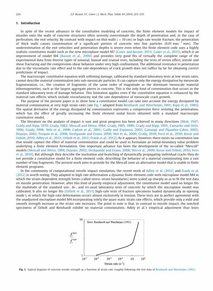
The purpose of the present paper is to show how a constitutive model can take into account the energy dissipated bymaterial comminution at very high strain rates (see Fig. 1 adapted from Reinhardt and Weerheijm, 1991; Kipp et al., 1980).The spatial derivative of the energy dissipated by comminution represents a compressive force resisting the penetration,which has the effect of greatly increasing the finite element nodal forces obtained with a standard macroscopicconstitutive model.
The literature on the analysis of impact is vast and great progress has been achieved in many directions (Mott, 1947;Grady and Kipp, 1979; Grady, 1982; Mescall and Weiss, 1984; Grady, 1985, 1990; Grady and Kipp, 1995; Camacho and Ortiz,1996; Grady, 1998; Shih et al., 1998; Cadoni et al., 2001; Gailly and Espinosa, 2002; Gatuingt and Pijaudier-Cabot, 2002;Doyoyo, 2002; Forquin et al., 2008; Deshpande and Evans, 2008; Wei et al., 2009; Grady, 2010; Ferri et al., 2010; Kožar andOžbolt, 2010; Adley et al., 2012; Ožbolt et al., 2011; Frank et al., 2012). As it appears, however, there exists no constitutive lawthat would capture the effect of material comminution and could be used to formulate an initial-boundary value problemunderlying a finite element formulation. One important advance has been the development of the so-called “Mescall”models (Mescall and Weiss, 1984; Doyoyo, 2002; Deshpande and Evans, 2008; Wei et al., 2009; Kožar and Ožbolt, 2010; Ferriet al., 2010). But although they describe the nucleation and branching of dynamically propagating individual cracks they donot provide a constitutive model for a finite element code, describing the behavior of a material comminuting into a vastnumber of tiny fragments. The present work aims to provide for the Mescall zone an alternative model that is usable in finiteelement programs.
In the community of computational missile impact simulation, the recent work of Adley et al. (2012) and Frank et al.(2012) is worth noting. They adapted to high rate deformation a dynamic finite element code with microplane model M4 inwhich the strain-dependent strength limits (called stress–strain boundaries) were scaled up sharply so as to fit the test dataon missile penetration. However, after this kind of purely empirical adjustment, the constitutive model used no longer fitsthe multitude of the standard uni-, bi-, and tri-axial laboratory tests of concrete by which the microplane model wascalibrated. It also no longer fits (Ožbolt et al., 2011) high-rate tests of fracture specimens loaded dynamically in openingmode I, in which the high-rate deformation occurs almost exclusively in tension. These tests are in perfect agreement withthe unadjusted microplane model M4 incorporating solely the quasi-static strain rate effects, which provide only a mild andsmooth strength increase as the strain rate increases. The point to note is that, in contrast to missile impact, the notchedspecimens of Ožbolt and Reinhardt exhibit no material comminution. Adley et al.'s empirical adjustment thus loses
Fig. 1. Typical diagram of concrete tensile strength as a function of strain rate, roughly following the test data of Reinhardt and Weerheijm (1991).
Z.P. Bažant, F.C. Caner / J. Mech. Phys. Solids 64 (2014) 223–235 225
predictive capability except for situations very similar to those for which the microplane strength limits havebeen adjusted.
The theory proposed here is partly inspired by analogy with turbulence. In high velocity turbulent flow, the energydissipation rate is greatly enhanced by the formation of micro-vortices (eddies) which dissipate energy by viscous shearstress. By analogy, it is assumed that the energy dissipation at fast deformation of a confined solid gets greatly enhanced bythe release of kinetic energy of high shear strain rate of forming particles. Another inspiration for the present model isGrady's model for explosion in a hollow sphere (Grady, 1982), in which the kinetic energy of volumetric strain is consideredas the driving force of comminution. Grady calculated and experimentally justified that, in rapid volumetric expansion, theaverage particle size is
s ¼ 48Γρ_ε2V
!1=3
ð1Þ
where Γ is the interface fracture energy, ρ is the mass density and _εV is the expansive volumetric strain rate. In later works(Grady, 1990; Grady and Kipp, 1995; Grady, 1998, 2010) he demonstrated by experiments that this equation can be extendedto comminution under impact, but did not justify it theoretically. Here the extension of Grady's equation to impact istheoretically justified by noting that comminution under impact must be driven by the release of the local kinetic energy ofshear strain rate. This basic idea is then used to develop a coherent constitutive model.
The presently proposed formulation is a continuum model that smears the sub-scale cracking. A number of continuummodels that homogenize the sub-scale cracking of concrete, sea ice and other brittle heterogeneous materials have beenproposed in the past (e.g. Bažant and Lin, 1988; Jirásek and Bažant, 1995). Gao and Klein (1998) and Klein and Gao (1998)consider a random network of cohesive bonds on the microscale and obtain the continuum model via the Cauchy–Born rule, i.e.,by equating the strain energy of the continuum to the potential energy of the micro-scale bonds. However, all these modelsconsider the fracturing to be caused by the release of strain energy. The present model is based on the fact that, at high ratedeformation, it is the release of local kinetic energy that matters. This idea was outlined in a brief paper (Bažant and Caner, 2013)motivated by the recently proposed concept of shock fracturing of gas shale, and is here developed in detail.
This paper presents the theory. The following paper (Caner and Bažant, this issue) presents the numerical validation bylarge-scale finite element simulations of missile impact and by the simulation of Hopkinson bar tests of strength. Thesesimulations use the microplane model M7 with comminution enhancement.
2. Local kinetic energy density of comminuting micro-particles at high shear rate
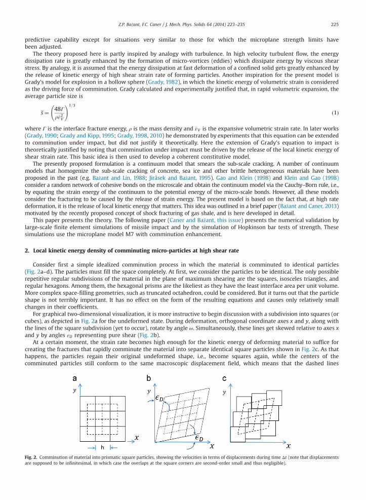
Consider first a simple idealized comminution process in which the material is comminuted to identical particles(Fig. 2a–d). The particles must fill the space completely. At first, we consider the particles to be identical. The only possiblerepetitive regular subdivisions of the material in the plane of maximum shearing are the squares, isosceles triangles, andregular hexagons. Among them, the hexagonal prisms are the likeliest as they have the least interface area per unit volume.More complex space-filling geometries, such as truncated octahedron, could be considered. But it turns out that the particleshape is not terribly important. It has no effect on the form of the resulting equations and causes only relatively smallchanges in their coefficients.
For graphical two-dimensional visualization, it is more instructive to begin discussion with a subdivision into squares (orcubes), as depicted in Fig. 2a for the undeformed state. During deformation, orthogonal coordinate axes x and y, along withthe lines of the square subdivision (yet to occur), rotate by angle ω. Simultaneously, these lines get skewed relative to axes xand y by angles εD representing pure shear (Fig. 2b).
At a certain moment, the strain rate becomes high enough for the kinetic energy of deforming material to suffice forcreating the fractures that rapidly comminute the material into separate identical square particles shown in Fig. 2c. As thathappens, the particles regain their original undeformed shape, i.e., become squares again, while the centers of thecomminuted particles still conform to the same macroscopic displacement field, which means that the dashed lines
Fig. 2. Comminution of material into prismatic square particles, showing the velocities in terms of displacements during time Δt (note that displacementsare supposed to be infinitesimal, in which case the overlaps at the square corners are second-order small and thus negligible).
Z.P. Bažant, F.C. Caner / J. Mech. Phys. Solids 64 (2014) 223–235226
connecting these centers are identical in Fig. 2b and c (we ignore the necessary crushing of the particle corners since theirvolume is second-order small).
As the particles return to their near-original shape, they release their kinetic energy ΔK while the opposite faces ofneighboring particles slip against each other, as marked by double arrows in Fig. 2c.
The global kinetic energy, which excludes the kinetic energy of shear strain rate of the particles, is in two dimensions,defined as
K ¼∑ih3
ρ
2ð _u2
0þ _v20Þi ð2Þ
(where _u0; _v0 are the velocity components of the centers i¼ 1;2;3;… of the particles or of the eddies, and h is the side of thesquares) remains unchanged as the particles separate.
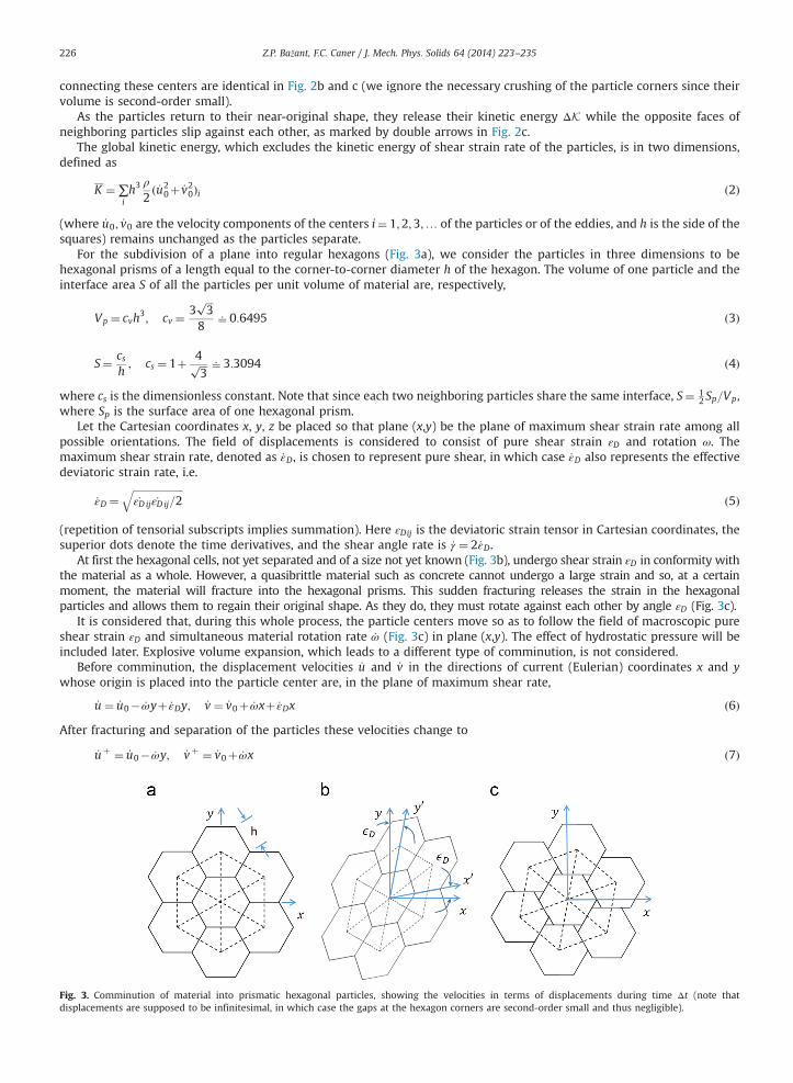
For the subdivision of a plane into regular hexagons (Fig. 3a), we consider the particles in three dimensions to behexagonal prisms of a length equal to the corner-to-corner diameter h of the hexagon. The volume of one particle and theinterface area S of all the particles per unit volume of material are, respectively,
Vp ¼ cvh3; cv ¼
3ffiffiffi3
p
860:6495 ð3Þ
S¼ csh; cs ¼ 1þ 4ffiffiffi
3p 63:3094 ð4Þ
where cs is the dimensionless constant. Note that since each two neighboring particles share the same interface, S¼ 12 Sp=Vp,
where Sp is the surface area of one hexagonal prism.Let the Cartesian coordinates x, y, z be placed so that plane (x,y) be the plane of maximum shear strain rate among all
possible orientations. The field of displacements is considered to consist of pure shear strain εD and rotation ω. Themaximum shear strain rate, denoted as _εD, is chosen to represent pure shear, in which case _εD also represents the effectivedeviatoric strain rate, i.e.
_εD ¼ffiffiffiffiffiffiffiffiffiffiffiffiffiffiffiffiffiffiffiffi_εD ij _εD ij=2
qð5Þ
(repetition of tensorial subscripts implies summation). Here εDij is the deviatoric strain tensor in Cartesian coordinates, thesuperior dots denote the time derivatives, and the shear angle rate is _γ ¼ 2_εD.
At first the hexagonal cells, not yet separated and of a size not yet known (Fig. 3b), undergo shear strain εD in conformity withthe material as a whole. However, a quasibrittle material such as concrete cannot undergo a large strain and so, at a certainmoment, the material will fracture into the hexagonal prisms. This sudden fracturing releases the strain in the hexagonalparticles and allows them to regain their original shape. As they do, they must rotate against each other by angle εD (Fig. 3c).
It is considered that, during this whole process, the particle centers move so as to follow the field of macroscopic pureshear strain εD and simultaneous material rotation rate _ω (Fig. 3c) in plane (x,y). The effect of hydrostatic pressure will beincluded later. Explosive volume expansion, which leads to a different type of comminution, is not considered.
Before comminution, the displacement velocities _u and _v in the directions of current (Eulerian) coordinates x and ywhose origin is placed into the particle center are, in the plane of maximum shear rate,
_u ¼ _u0� _ωyþ _εDy; _v ¼ _v0þ _ωxþ _εDx ð6Þ
After fracturing and separation of the particles these velocities change to
_uþ ¼ _u0� _ωy; _vþ ¼ _v0þ _ωx ð7Þ
Fig. 3. Comminution of material into prismatic hexagonal particles, showing the velocities in terms of displacements during time Δt (note thatdisplacements are supposed to be infinitesimal, in which case the gaps at the hexagon corners are second-order small and thus negligible).
Z.P. Bažant, F.C. Caner / J. Mech. Phys. Solids 64 (2014) 223–235 227
The drop in kinetic energy of each cell is
�VpΔK¼ hZA
ρ
2_u2þ _v2�ð _uþ Þ2�ð _vþ Þ2� �
dA ð8Þ
�VpΔK¼ hρ2
_ε2D
ZAx2þy2� �
dAþhρZA
_v0 _εDxþ _u0 _εDyþ _εD _ω x2�y2� �� �
dA ð9Þ
�VpΔK¼ hρ2
_ε2D
ZAr2 dA¼ hρ
2Ip _ε2D ð10Þ
or, per unit volume of material,
ΔK¼ �ckρh2 _ε2D ð11Þ
where
Ip ¼ffiffiffi3
p
32h460:05413h4; ck ¼
Ip2hVp
60:04167 ð12Þ
here ΔK is the drop of kinetic energy of the particle per unit volume, ck is the dimensionless coefficient of kinetic energy, ρ isthe mass density, A is the area of the hexagon, r is the radial coordinate, Ip ¼ Ixþ Iy is the centroidal polar moment of inertiaof the hexagon (and Ix, Iy is the moments of inertia about axes x and y, the orientation of which does not matter).
Note that, if the global motion is characterized by the velocities of particle centroids, the second integral in Eq. (9)vanishes. Actually this is exactly true only when Ix¼ Iy, which occurs for cubes, but only approximately for hexagons. Alsonote that the material rotation velocity _ω has no effect on K. Indeed, it ought to be so, since rigid body rotations can cause nofracturing. Thus it is proven that the global and local kinetic energy densities are, in two dimensions, separable.
3. Separability of local and global kinetic energy in three dimensions
In three dimensions, the axial vector of local rotation rate, _ω, does not have to be orthogonal to plane (x,y) of maximumshear rate. It may be decomposed as
_ω ¼ _ωNþ _ωP ð13Þwhere _ωN ; _ωP are the axial vectors of the components normal to plane (x,y) of maximum shear and parallel to that plane.Instead of Eq. (8), the density difference between the total kinetic energy and the kinetic energy of corresponding to velocityvector v0 at particle center becomes
�VpΔK¼ ρ
2
ZVp
ðv0þ _ω � xþ _ϵ � xÞ2�ðv0þ _ω � xÞ2h i
dV ð14Þ
�VpΔK¼ ρ
2
ZVp
ð_ϵ � xÞ2 dVþρ
ZVp
_ϵ � xð Þ � _ωN � xð Þ dVþρ
ZVp
_ϵ � xð Þ � _ωP � xð Þ dV ð15Þ
where the integral of v0 � ð_ϵ � xÞ has vanished by virtue of symmetry; _ϵ is the strain rate tensor, _ϵ � x is the strain rate vectoron plane (x,y); and x is the vector of coordinates x,y centered at particle center. The second integral in Eq. (15) corresponds torotation within plane (x,y) of maximum shear rate _εD, and so the first two integrals are equivalent to the previous two-dimensional analysis in Eq. (10).
The third integral in Eq. (15) corresponds to rotation in a plane normal to the plane (x,y) of maximum shear rate _εD. Thisintegral is in general nonzero. But it seems impossible that a rotation in a plane normal to (x,y), i.e., a rotation about a vectorlying in plane (x,y), could contribute to comminution in plane (x,y). It could affect comminution only in a plane normal to (x,y). Therefore, the kinetic energy corresponding to the last term in Eq. (15) can be ignored, and Eq. (11) should be applicableto all situations.
4. Partial analogy with turbulence
It is interesting that the kinetic energy Kshear of a particle deforming by pure shear at rate _εD happens to be the same asthe kinetic energy Keddy of the same particle rotating as a rigid body at angular rate _ω ¼ _εD. Indeed, the squares of thevelocity magnitudes in the comminuting particle with shear strain rate _ωD and in a turbulence vortex (eddy) treatedapproximately as a small rigid domain of area A with angular flow velocity _ω can be used, respectively, to calculate the localkinetic energies:
Kshear ¼ZA
ρ
2jvj2 dA¼
ZA
ρ
2ð_εDyÞ2þð_εDxÞ2h i
dA ð16Þ
Keddy ¼ZA
ρ
2jvj2 dA¼
ZA
ρ
2ð _ωyÞ2þð _ωxÞ2h i
dA ð17Þ
Z.P. Bažant, F.C. Caner / J. Mech. Phys. Solids 64 (2014) 223–235228
Now note that when _ω ¼ _εD,
Kshear ¼Keddy ð18Þeven though the velocity vectors at the corresponding points do not have the same directions.
This observation reveals a partial analogy with turbulence (Tennekes and Lumley, 1972), which is what inspired thepresent theory. In both comminution and turbulence, the micro-level kinetic energy (Eq. (16) or (17)) augments the kineticenergy of the macro-level part of the turbulent flow of a fluid, or the macrolevel kinetic energy of the assembly of thecomminuting particles, which in both cases is equal to
∑i
ρ
2ð _u2
0þ _v20Þi ð19Þ
where _u0; _v0 denote the velocity components of the centers i¼ 1;2;3;… of the particles or of the eddies. The micro-levelkinetic energy gets dissipated by fluid viscosity in the eddies of turbulent flow, or the by the energy of interface fracture ofthe comminuting particles. In both cases, minimization of the total energy of motion requires a micro-level energydissipation mechanism consisting of eddy formation or comminution.
When the local motion of a shear strain field continues after the break of the interface, interface slips (like those from (b)to (c) in Fig. 3) must get repeated. But in contrast to the rotational motion in a turbulent eddy, the interface slips cannotcontinue indefinitely because the shear angle cannot be infinite.
5. Approximate generalization to randomly distributed particle sizes
Limiting consideration to micro-particles of one size would be an oversimplification. It is well-known that, in all sorts ofdynamic comminution, the particle sizes vary randomly. The frequency distribution of particle sizes may approximately bedescribed by Schuhmann's power law (Schuhmann, 1940; Charles, 1957; Ouchterlony, 2005; Cunningham, 1987). This lawwas found to give realistic results for, e.g., the particle sizes and the resisting force due to comminution of concrete slabsduring the collapse of the World Trade Center towers (Bažant et al., 2008). The Schuhmann law is described by a power-lawcumulative distribution function of particle size s:
F sð Þ ¼ sk�hk
Hk�hksA h;Hð Þ; F sð ÞA 0;1ð Þ� � ð20Þ
where k is a empirical constant (typically k� 0:5), h¼smin is the minimum micro-particle size, and H¼smax is the maximummicro-particle size (usually H/h¼10–100). Other particle size distributions have also been used (Mott, 1947; Grady, 1990)and the analysis that follows can be readily adapted to any one of them.
Within the size interval ðs; sþdsÞ, the number of micro-particles per unit volume is dFðsÞ=s3. The average particle size iss ¼ RH
h s dFðsÞ ors ¼ ch ð21Þ
where c ¼ kkþ1
ðH=hÞkþ1�1
ðH=hÞk�1ð22Þ
Since, for size s, the particle interface area per unit volume is cs=s, the combined interface area of all the micro-particlesor random sizes per unit volume is
S¼Z H
s ¼ h
css
dF sð Þ ¼ Cs
hð23Þ
where Cs ¼cskk�1
ðH=hÞk�1�1
ðH=hÞk�1ð24Þ
Cs is a dimensionless constant. It may be checked (with the aid of L'Hospital rule) that the limit of Eq. (23) for H=h-1 is cs, asit must.
Note that, in this calculation, we did not address the fact that particles of unequal sizes cannot all be hexagonal prisms.This means that their closest packing may leave some empty interparticle spaces and would thus require a certain volumedilation, and also that particles of diverse shapes will be created. For simplicity, we do not analyze this dilation and shapediversity.
To calculate the kinetic energy loss, we introduce the simplifying hypothesis that it is possible to superpose thecontributions calculated for various uniform particle sizes as if the particles of each size were distributed regularly. The lossof kinetic energy of the particles of all the sizes per unit volume (dimension J/m3 or N/m2) may then be obtained, accordingto Eq. (11), as follows:
ΔK¼ �Z H
s ¼ hckρs
2 _ε2D dFðsÞ ð25Þ
Z.P. Bažant, F.C. Caner / J. Mech. Phys. Solids 64 (2014) 223–235 229
The integration yields
ΔK¼ �Ckρh2 _ε2D ð26Þ
where Ck ¼k
kþ2ðH=hÞkþ2�1
ðH=hÞk�1ck ð27Þ
Cs is a dimensionless constant. For the limit case of particles of one size h, one may check that limH=h-1 Ck ¼ ck, as required.To illustrate the effect of the choice of particle shape, assuming H/h¼100, one obtains for hexagonal and cubical particlesrespectively Cs¼0.331, 0.300 and Ck¼92.6, 138.9. These differences are not large and the form of the equations remainsthe same.
6. Release of local kinetic energy of strain rate as the driving force of dynamic fracturing
The total energy of the comminuted particles per unit volume is
F ¼KþSΓ ð28Þwhere Γ is the interface fracture energy of the comminuting particles (dimension J/m2 or N/m). To formulate the criterion ofdynamic fracturing, one must choose between two theoretically possible forms:
either∂F∂S
¼ 0 ð29Þ
or �ΔK ¼ SΓ ð30ÞIn the former case, by analogy to classical fracture mechanics, it is assumed that once the fracture is triggered in a part ofsurface S, it will propagate. In the latter case, it is assumed that the entire surface forms simultaneously. The latter casewould apply if the continuum strain rate were so high that the duration of comminution would require the fracture topropagate faster than the maximum possible crack propagation rate, which is the Raleigh wave speed. The results of analysisfor both cases are very similar and differ only in dimensionless empirical coefficients. In what follows we will consider thatthe former case applies. Thus, according to Eq. (29), it is required that
� ∂ðΔKÞ∂S
¼ � ∂ðΔKÞ=∂hdS=dh
¼ Γ ð31Þ
This equation is similar to that used in Grady's (1982) analysis of tensile comminution due to high volumetric strain rate inan explosion within the center of a hollow sphere (see also Freund, 1990, Eq. (8.7.3)). It is seen to be analogous to the energyrelease criterion of fracture mechanics. In fact, it could have been derived directly from the condition of criticality: When thecomminution gets under way, the rate of release of kinetic energy (with respect to S) at the given kinematic constraint(i.e., at given _εD) must be equal to the surface energy Γ.
Note that Eq. (31) may also be considered as a special case of Eqs. (5.3.2) and (5.3.20) in Freund (1990) when the strainenergy density is neglected. But these are valid only for moderately high strain rates in which the kinetic energy densitydoes not exceed the strain energy density in the material by an order of magnitude or more.
Eq. (30) imposes an overall energy balance condition which does not ensure incremental energy balance and thus doesnot guarantee the interface fracture to begin. On the other hand, like in classical fracture mechanics, Eq. (31) means that assoon as energy balance is satisfied incrementally, the fracture can occur, and must occur if the kinetic energy density isincreased further.
Substitution of Eqs. (26) and (23) into (31) and differentiation furnish the minimum particle size:
h¼ smin ¼CaΓ
ρ_ε2D
!1=3
ð32Þ
where Ca ¼csck
ðkþ2Þðk�1Þ
ðk�1ÞðH=hÞk�kðH=hÞk�1þ1
kðH=hÞkþ2�ðkþ2ÞðH=hÞkþ2ð33Þ
If H/h¼100, then Ca¼0.032 for hexagonal prisms and Ca¼0.019 for cubical prisms. Thus we see again that the preciseparticle shape does not make a large difference. According to Eq. (21), the average particle size is then obtained as s ¼ ch.
The maximum particle size H is approximately known. It must be one order of magnitude smaller than da, i.e.,
H� 0:1da ð34Þbecause fragmentation into particles of the same order of magnitude as da is covered by the constitutive law based on staticmaterial tests with post-peak softening. Therefore, H must be about 2–4 mm for normal concrete, and 0.05–2 mm for highstrength concrete. Thus, to calculate h, one must substitute Eq. (32) into (33) and then solve the resulting nonlinear algebraicequation for h iteratively, e.g., by the Newton method. The ratio H/h then follows.
Z.P. Bažant, F.C. Caner / J. Mech. Phys. Solids 64 (2014) 223–235230
Eq. (32) agrees with Grady's formula (1), which was justified empirically by observations of particle sizes in impact tests.This provides one verification of the present theory.
Substitution of Eq. (32) into Eq. (26) further yields
�ΔK¼ ðC0Γ2ρÞ1=3 _ε2=3D where C0 ¼ C3
kC2a ð35Þ
where C0 ¼ 822 for hexagonal prisms and C0 ¼ 1013 for cubical particles, assuming H/h¼100. Again the difference thatresults from different particle shapes is not large.
7. Dimensionless number separating fractures driven by kinetic and strain energies
What is the critical strain rate beyond which the fracturing driven by the release of kinetic energy of strain rate, �ΔK,dominates over the fracturing of classical type driven by the release of strain energy U? To answer it, we must also include Uin the energy balance. As is clear from Fig. 3, the domains of the particles to form are initially deformed by locally uniformshear strain γ ¼ 2εD and after comminution fracture they become undeformed. So the strain energy release due tocomminution fracture is U ¼ τ2=2G where G is the elastic shear modulus and τ is the shear stress. According to Eq. (35), wehave
� ΔKU ¼ Ba ð36Þ
Ba ¼G
Cgτ2ðΓ2ρ_ε2DÞ1=3 ð37Þ
where Cg ¼ C�1=30 =2¼ 1=ð2CkC
2=3a Þ ¼ 0:2656 for H=h¼ 10 ð38Þ
where Cg is a dimensionless geometry factor depending on the particle shape and the type of frequency distribution ofparticle sizes. For H/h¼10 and for the hexagonal particles distributed according the Schuhmann law, Cg¼0.2656. For othershapes, distributions and ratios H/h, different values will be obtained but they will generally be of the order of 1. Ba is adimensionless number, an indicator of the onset of comminution, characterizing the importance of kinetic shear fracturingin the comminution process. The comminution is
kinetic energy driven if Bab1in transition if Ba � 1absent or static if Ba51 ð39Þ
Since τ at comminution cannot be larger than the shear strength or yield stress τ0, the use of τ¼ τ0 in the condition Bab1gives a sufficient condition for comminution to be driven by the kinetic energy alone.
In the flow of fluids, the dimensionless Reynolds number gives the threshold beyond which the local kinetic energy dueto eddies begins to control the resistance to flow. Likewise, Ba is a dimensionless number that defines the threshold beyondwhich the local kinetic energy due to shear strain rate begins to control the resistance to deformation. This is anotherfeature of the turbulence analogy.
Expressing _εD from Eq. (32) and substituting it into (37), one gets an alternative expression for the dimensionlessindicator:
Ba ¼C1=3a
Cg
GΓτ20h
ð40Þ
8. Some numerical estimates and discussion
Let us now estimate the dimensionless number Ba for shear comminution of concrete. While, at the macroscale, thefracture energy of concrete is about 100 J/m2, for sub-millimeter particles it is probably much smaller, perhaps Γ¼10 J/m2¼10 kg/s2, because the fracture process zone is much narrower. Further we may consider τ0¼3 MPa¼3�106 kg s�2 m�1, G¼10.59 GPa¼10.59 �109 kg s�2 m�1, and ρ¼2300 kg/m3. Assuming H/h¼10 and H¼9.43 mm (or_εD ¼ 100 s�1), we have Ba¼5.85. Considering the strain rates _εD ¼ 104=s and 106/s, we get from Eq. (36):
� ΔKU ¼ 126 and 2715 ð41Þ
respectively. So, at these rates, the deformation is almost totally dominated by the kinetic energy of strain rate. In a similarway, one finds that
�ΔK=δU ¼ 1 when _ε ¼ 7:075=s: ð42ÞSince the values of Γ and τ0 at sub-millimeter scale are highly uncertain, the foregoing estimates must, of course, beregarded as very crude. It is better to calibrate the computational model by fitting impact test data.
Z.P. Bažant, F.C. Caner / J. Mech. Phys. Solids 64 (2014) 223–235 231
Let us now estimate the particle size. We assume the same values of Γ and ρ as before and (for _εD ¼ 104 s�1, H/h¼10 andk¼0.5) we calculate Ca¼1.929. From Eq. (32) with (33), we get the minimum and mean particle sizes:
h¼ 0:4377 mm for _εD ¼ 104=s; h¼ 0:0943 mm for _εD ¼ 105=s ð43Þ
s ¼ 2:066 mm for _εD ¼ 104=s; s ¼ 0:4452 mm for _εD ¼ 105=s ð44ÞUnder high confining hydrostatic pressure p, say p¼ 10τ0, the effective fracture energy might increase significantly. This
would increase the foregoing estimates of threshold and particle size. But under high enough pressure the material wouldbehave plastically and would not comminute.
Another point to note is that the release of strain energy U does not lead to dependence of fracturing on the strain rate.Rather, it leads to a dependence on the magnitude of applied stress or strain, which is already accounted for by the softeningpart of the constitutive relation.
9. Implementation of kinetic rate effect
Energy conservation requires that K¼D¼ energy dissipated per unit volume (dimension J/m3). As the same time, sincethe stress (dimension N/m2) is the energy per unit volume, DK¼ sA ¼ additional stress due to comminution. There are twopossible approaches to enforce this energy dissipation in a finite element program:
(1)
Either as a distributed body forcef ¼ ∂K=∂x ðDK¼D¼ sAÞ ð45Þwhich gets translated into equivalent nodal forces (x¼ global coordinate vector formed from Cartesian coordinatesxi; i¼ 1;2;3Þ;
(2)
Or as an additional stress, sA ¼D, to be implemented in the constitutive equation. We favor this approach as it seemssimpler for programming, and also is more versatile as it allows generalization to different types of comminution.Since one may write sA ¼D¼ η_ε, the additional (apparent) viscous stress sA may be implemented as kinetic (or apparent)viscosity η¼D=_ε ¼ �ΔK=_ε. But this equation would be acceptable only in a uniaxial model. In a triaxial constitutive model,the additional viscous stress should be applied only to the stress components that represent shear, i.e., as additionaldeviatoric stress components sij
A, which must be added to the stresses obtained from the standard quasi-static
constitutive model.To ensure tensorial invariance, powers of the tensorial components are inadmissible. Only a tensorial invariant can be
raised to a power. So we use again the effective deviatoric strain rate given by Eq. (5). Since the energy density has the samedimension as the stress, it is convenient to introduce equivalent viscosity ηD such that the viscous stress–strain relation
sAij ¼ ηD _εD ij ð46Þ
where
ηD ¼ ðC0Γ2ρÞ1=3 _ε �1=3
D ð47Þwould give the same energy dissipation density as Eq. (35) for any possible deviatoric strain rate tensor _εD ij, in thevariational sense. Now, because the energy density is the same as the stress, sA12 must be equal to ΔK when all othertensorial components vanish. Since ΔK is a tensorial invariant, it is thus necessary that
�ΔK¼ffiffiffiffiffiffiffiffiffiffiffiffiffiffisAijs
Aij=2
qð48Þ
In view of Eq. (46), we may then writeffiffiffiffiffiffiffiffiffiffiffiffiffiffisAijs
Aij=2
q¼ ηD
ffiffiffiffiffiffiffiffiffiffiffiffiffiffiffiffiffiffiffiffi_εD ij _εD ij=2
q¼ ηD _εD ð49Þ
where _εD ¼ ffiffiffiffiffiffiffiffiffiffiffiffiffiffiffiffiffiffiffiffi_εD ij _εD ij=2
p. This is a tensorial invariant which simplifies to pure shear rate _εD when _εD 12 is the only nonzero
component.This analysis shows that the energy sink due to the comminution process may be modeled by equivalent apparent
viscosity ηD. This is the simplest way to implement the comminution effect in finite element programs. It can be combinedwith any constitutive law.
The enhancement of the dissipative viscous resistance to shearing is a similar feature as the enhancement of viscousresistance caused by eddies in turbulent flow. This is another aspect of analogy with turbulence.
A stress increase proportional to _ε2=3 gives an enormous rate effect on the apparent material strength, but only at veryhigh strain rates. To illustrate this, consider that the strength or yield limit is scaled up by a rate-dependent factor, r, andnote that, according to the test data in the literature, the rate effect beyond that explained by viscoelasticity and static crackgrowth rate is detectable only for rates _ε41=s. Knowing this fact suffices to estimate the rate effect magnitude. Assuming
Z.P. Bažant, F.C. Caner / J. Mech. Phys. Solids 64 (2014) 223–235232
that the error of the data is not below 1%, we have 12=3r¼ 0:01, fromwhich r¼0.01. So, e.g., at the strain rate of 105/s one hasð105Þ2=3r¼ 21:5. This is the ratio by which the stress must be increased, by means of apparent viscosity.
10. Generalization to kinetic energy of volume expansion and its apparent viscosity
In some situations, the rate of volumetric strain εV ¼ εkk=3 can be so high that the volumetric kinetic energy issignificantly contributing to the comminution (such a case was shown by Grady (1982, 1985) in his analysis of an explosionwithin a hollow sphere). In that case, Eqs. (6) need to be generalized as
_u ¼ _u0� _ωyþ _εDyþ _εExx; _v ¼ _v0þ _ωxþ _εDxþ _εExy ð50Þin which
_εEx ¼ddt
εkk3
D E ¼ _εV if _εV 40 and εV 40
0 otherwise
�ð51Þ
and t is the time, _εEx represents the expansive strain rate which is such that no comminution occurs if either the volumetricstrain rate is compressive or if the volumetric strain is compressive (i.e., negative). Noting that Eq. (7) remains unchanged,one finds that Eqs. (26) and (35) for the drop of kinetic energy per unit volume of material must now be generalized asfollows:
�ΔK¼ Ckρh2ð_ε2Dþ _ε2ExÞ ð52Þ
�ΔK¼ ðC0Γ2ρÞ1=3ð_ε2Dþ _ε2ExÞ1=3 ð53Þ
This means that, in the remaining equations, _ε2D must now be replaced by _ε2Dþ _ε2Ex. Hence, Eq. (32) must be generalized as
h¼ smin ¼CaΓ
ρð_ε2Dþ _ε2ExÞ
!1=3
ð54Þ
Eq. (46) must now be combined with the additional apparent tensile volumetric viscous stress, as follows:
sAij ¼ ηD _eij; sAV ¼ ηV _εEx ð55Þ
in which
ηV ¼ ðC0Γ2ρÞ1=3 _ε�1=3
Ex ð56Þhere ηV is the volumetric kinetic (or apparent) viscosity.
Numerical simulations nevertheless show that the generalization for _εEx has virtually no effect in impact problems.
11. Static-to-kinetic transition of rate effect and apparent viscosity
Eq. (47) cannot be applied to very small loading rates, for two reasons: (1) numerical, because the viscosity wouldbecome infinite when _εD-0 and would thus cause the computer program to diverge if _εD happens to be small enough and(2) physical, because the comminution by local kinetic energy does not exist according to Eq. (39) when Ba51. Thus, theremust be a transition from finite to zero viscosity, centered at Ba¼1.
To deduce this transition, we must replace function _ε�1=3D by a function that is asymptotically finite or zero when _εD-0
but remains asymptotically unchanged for high _εD. To this end, we express _εD from Eq. (37) and substitute it into Eq. (47) toexpress the viscosity in terms of Ba:
ηD ¼ Γ
τ0
C2=30 GρCgBa
!1=2
ð57Þ
This equation may now be replaced by the following:
ηD ¼ Γ
τ0
C2=30 GρCg
Bn�1a
1þBna
!1=2
ð58Þ
where n is an empirical constant controlling how sharp the transition is; nZ1 (calculations used n¼2).The foregoing equation is the final expression for the kinetic viscosity, with corrected low-rate asymptotics. It is identical
to Eqs. (47) and (57) when Bab1 and gives a zero or negligible finite viscosity when Ba51, as required by (39).
12. Possible variability of Γ , work of friction and effect of pressure
When a high shear strain rate continues after the initial comminution by interface fracture, Γ plays the role of frictionalwork, i.e., the work of frictional shear stress τ on unit displacement. If _εD after initial comminution decreases while still
Z.P. Bažant, F.C. Caner / J. Mech. Phys. Solids 64 (2014) 223–235 233
remaining in the comminution range according to Eq. (37), the energy balance requires the frictional slip to be concentratedinto interfaces spaced farther apart than particle size. Thus groups of particles moving as virtually rigid blocks must formand Γ then represents the work of friction between these blocks. On the other hand, if the shear strain rate after the initialcomminution increases further, the particles already comminuted must be getting comminuted further (or fractured) tosmaller sizes.
Since friction decreases with increasing slip rate, the frictional work may be decreasing with increasing strain rate. Thiseffect could be approximately captured by setting
Γp _ε�qD ðqZ0Þ ð59Þ
However, to verify such an effect and determine the value of q, further more detailed test data will be necessary. In datafitting thus far, the possible effect of _ε on Γ has been neglected.
Note that exponent �1/3 in Eq. (47) has been derived for constant Γ. However, if Γ as a characteristic of post-fracturefrictional work decreases with the slip rate or shear strain rate according to the power law in Eq. (59), it would reduce theexponent in Eq. (47) below �1/3. However, the particle size given by Eq. (32) would not be affected since it depends on thefracture energy rather than the subsequent frictional slip.
When the high-rate shearing occurs under high hydrostatic pressure p, the effective value of Γ in the sense of fractureenergy as well as frictional work may increase as a function of p.
It may be noted that a different fracture energy and particle size effects have been observed in the case of dynamicerosion of a solid surface by impinging hard particles (Tilly and Sage, 1970). However, this is a fundamentally differentproblem to which the present theory does not apply.
13. Conclusions
1.
The local kinetic energy of motion associated with high shear strain rates (4102=s) is sufficient to provide the surfacefracture energy necessary for comminution of materials such as concrete into fine particle.2.
At very high strain rates, kinetic energy of strain rate is orders of magnitude higher than the strain energy. Hence, theclassical fracture mechanics does not apply.3.
The dissipated energy depends on the particle size distribution, which is here assumed to follow the Schuhmannpower law.4.
The minimum or average particle size follows from the condition that the rate of release of kinetic energy of shear strainrate must be equal to the rate of energy dissipation due to growing area of interparticle fractures. The minimum particlesize predicted for missile impact at 310 m/s is of the order of 0.15 mm.5.
The main characteristic of the comminution effect is a dimensionless number Ba (Eq. (37)) representing the ratio of localkinetic energy of shear strain rate to the maximum possible strain energy that can be stored in the same volume ofmaterial.6.
The present theory indicates that the density of kinetic energy available for comminution is proportional to the (2/3)power of the shear strain rate, the particle size or crack spacing is proportional to the (�2/3) power of that rate, and theenergy dissipation by comminution is equivalent to a shear viscosity decreasing as the (�1/3) power of that rate. For astrain rate increase from 1/s to 105/s, the result is a roughly 20-fold increase of apparent material strength due tocomminution.7.
After comminution, the role of interface fracture energy changes to the work of interface frictional slip per unit relativedisplacement. If the interface friction depends on the slip rate, the exponent of strain rate giving the effective viscositycan change.8.
As one experimental justification, the present theory agrees with Grady's empirical observation that, in impact events,the average particle size is inversely proportional to the (2/3) power of the shear strain rate (Eq. (1)).9.
The theory can be extended in a similar way by including particle comminution due to kinetic energy of volumetricstrain rate, although, for missile impact, the volume expansion is not important.10.
The theory leads to a rate-dependent modification of constitutive equation calibrated only for static strain rate effects.Acknowledgments
The initial microplane modeling was supported under Grant W911NF-09-1-0043/P00003 from the U.S. Army ResearchOffice, Durham, to Northwestern University. The modeling of comminution due to local kinetic energy of strain rate wassupported by the Agency for Defense Development (ADD), Korea, through Grant 32788 from Daejeon University toNorthwestern University.
Z.P. Bažant, F.C. Caner / J. Mech. Phys. Solids 64 (2014) 223–235234
Appendix A. The alternative of increasing strength or yield limit
Since the energy per unit volume (dimension J/m3, with J¼N m) has the same dimension as the stress (dimension N/m2),an increase in the strain rate may alternatively be considered to cause an increase in the strength or yield limit in theconstitutive law. In the microplane model, the compressive deviatoric boundary curve for deviatoric stress sD, and thenormal boundary for tensile normal stress sN , respectively, may thus be scaled up by the kinetic factors:
rD ¼ ðCDΓ2ρÞ1=3⟨_εD⟩2=3; rV ¼ ðCVΓ
2ρÞ1=3⟨_εN⟩2=3 ðA:1Þ
where εD is now the microplane deviatoric strain component, εN the microplane normal strain component, and CV ;CD
microplane stiffness constants.Modeling of the enhanced resistance to high-velocity missile penetration by raising of the boundaries on the
microplanes was attempted by Adley et al. (2012) and Frank et al. (2012). They raised the boundaries purely empirically,in a way that allowed them to fit their missile penetration data.
However, in the microplane model there are many boundaries and each has a different and complicated shapecontrolling the triaxial behavior. Thus different boundaries and different parts of each boundary would have to be raised bydifferent ratios, which would reshape the boundaries. Unfortunately, it appears to be next to impossible to do that withoutloosing the foundation of the microplane model in the static triaxial test data. This is a serious objection to this kind ofempirical approach.
References
Adley, M.D., Frank, A.O., Danielson, K.T., 2012. The high-rate brittle microplane concrete model: part I: bounding curves and quasi-static fit to materialproperty data. Comput. Concr. 9, 293–310.
Bažant, Z.P., Caner, F.C., 2013. Comminution of solids caused by kinetic energy of high shear strain rate, with implications for impact, shock, and shalefracturing. Proc. Natl. Acad. Sci. 110 (48), 19291–19294.
Bažant, Z.P., Caner, F.C., Adley, M.D., A, A.S., 2000. Fracturing rate effect and creep in microplane model for dynamics. ASCE J. Eng. Mech. 126, 962–970.Bažant, Z.P., Le, J.L., Greening, F.R., Benson, D.B., 2008. What did and did not cause collapse of World Trade Center twin towers in New York? ASCE J. Eng.
Mech. 134, 892–906.Bažant, Z.P., Lin, F.B., 1988. Nonlocal smeared cracking model for concrete fracture. ASCE J. Struct. Eng. 114, 2493–2510.Cadoni, E., Labibes, K., Albertini, C., Berra, M., Giangrasso, M., 2001. Strain-rate effect on the tensile behaviour of concrete at different relative humidity
levels. Mater. Struct. 34 (January–February), 21–26 (RILEM, Paris).Camacho, G.T., Ortiz, M., 1996. Computational modelling of impact damage in brittle materials. Int. J. Solids Struct. 33, 2899–2938.Caner, F.C., Bažant, Z.P. Impact comminution of solids due to local kinetic energy of high shear strain rate: II. Microplane model and verification. J. Mech.
Phys. Solids, http://dx.doi.org/10.1016/j.jmps.2013.11.009, this issue.Caner, F.C., Bažant, Z.P., 2013. Microplane model M7 for plain concrete: I. Formulation. ASCE J. Eng. Mech. 139, 1714–1723.Caner, F.C., Bažant, Z.P., Wendner, R., 2013. Microplane model M7f for fiber reinforced concrete. Eng. Fract. Mech. 105, 41–57.Charles, R.J., 1957. Energy-size reduction relationships in comminution. Min. Eng. 9, 80–88.Cunningham, C., 1987. Fragmentation estimation and the Kuz–Ram model—four years on. In: Fourney, W.L., Dick, R.D. (Eds.), Proceedings of the Second
International Symposium on Rock Fragmentation by Blasting, SEM, Bethel, Connecticut, pp. 475–487.Deshpande, V.S., Evans, A.G., 2008. Inelastic deformation and energy dissipation in ceramics: a mechanism-based constitutive model. J. Mech. Phys. Solids
56, 3077–3100.Doyoyo, M., 2002. A theory of the densification-induced fragmentation in glasses and ceramics under dynamic compression. Int. J. Solids Struct. 39,
1833–1843.Ferri, E., Deshpande, V., Evans, A., 2010. The dynamic strength of a representative double layer prismatic core: a combined experimental, numerical, and
analytical assessment. ASME J. Appl. Mech. 77. 061011-1–061011-7.Forquin, P., Gary, G., Gatuingt, F., 2008. A testing technique for concrete under confinement at high rates of strain. Int. J. Impact Eng. 35, 425–446.Frank, A.O., Adley, M.D., Danielson, K.T., McDevitt, H.S., 2012. The high-rate brittle microplane concrete model: part II: application to projectile perforation
of concrete. Comput. Concr. 9, 311–325.Freund, L., 1990. Dynamic Fracture Mechanics. Cambridge University Press, Cambridge, UK.Gailly, B., Espinosa, H., 2002. Modelling of failure mode transition in ballistic penetration with a continuum model describing microcracking and flow of
pulverized media. Int. J. Numer. Methods Eng. 54, 365–398.Gao, H., Klein, P., 1998. Numerical simulation of crack growth in an isotropic solid with randomized internal cohesive bonds. J. Mech. Phys. Solids 46,
187–218.Gatuingt, F., Pijaudier-Cabot, G., 2002. Coupled damage and plasticity modelling in transient dynamic analysis of concrete. Int. J. Numer. Anal. Methods
Geomech. 26, 1–24.Grady, D.E., 1982. Local inertial effects in dynamic fragmentation. J. Appl. Phys. 53, 322–325.Grady, D.E., 1985. The mechanics of fracture under high-rate stress loading. In: Bažant, Z.P. (Ed.), Mechanics of Geomaterials. John Wiley, Chichester, UK,
pp. 129–156. (Chapter 7).Grady, D.E., 1990. Particle size statistics in dynamic fragmentation. J. Appl. Phys. 68, 6099–6105.Grady, D.E., 1998. Shock-wave compression of brittle solids. Mech. Mater. 29, 181–203.Grady, D.E., 2010. Length scales and size distributions in dynamic fragmentation. Int. J. Fract. 163, 85–99.Grady, D.E., Kipp, M.E., 1995. Experimental measurement of dynamic failure and fragmentation properties of metals. Int. J. Solids Struct. 32, 2779–2991.Grady, T.E., Kipp, M.E., 1979. The micromechanics of impact fracture of rock. Int. J. Rock Mech. Min. Sci. 16, 293–302.Jirásek, M., Bažant, Z.P., 1995. Particle model for quasibrittle fracture and application to sea ice. ASCE J. Eng. Mech. 121, 1016–1025.Kipp, M.E., Grady, D.E., Chen, E.P., 1980. Strain-rate dependent fracture initiation. Int. J. Fract. 16, 471–478.Klein, P., Gao, H., 1998. Crack nucleation and growth as strain localization in a virtual-bond continuum. Eng. Fract. Mech. 61, 21–48.Kožar, I., Ožbolt, J., 2010. Some aspects of load-rate sensitivity in visco-elastic microplane material model. Comput. Struct. 7, 317–329.Mescall, J., Weiss, V., 1984. Materials behavior under high stress and ultrahigh loading rates—part II. In: Proceedings of the 29th Sagamore Army Conference,
Army Materials and Mechanics Research Center, Watertown, Massachusetts.Mott, N.F., 1947. Fragmentation of shell cases. Proc. Roy. Soc. A 189, 300–308.Ouchterlony, F., 2005. The Swebrec function: linking fragmentation by blasting and crushing. Min. Technol. 114, A29–A44.Ožbolt, J., Sharma, A., Reinhardt, H.W., 2011. Dynamic fracture of concrete—compact tension specimen. Int. J. Solids Struct. 48, 1534–1543.

Z.P. Bažant, F.C. Caner / J. Mech. Phys. Solids 64 (2014) 223–235 235
Reinhardt, H.W., Weerheijm, J., 1991. Tensile fracture of concrete at high loading rates taking account of inertia and crack velocity effects. Int. J. Fract. 51,31–42.
Schuhmann, R.J., 1940. Principles of Comminution, I. Size Distribution and Surface Calculation. Technical Report. The American Institute of Mining,Metallurgical, and Petroleum Engineers (AIME).
Shih, C.J., Nesterenko, V.F., Meyers, M.A., 1998. High-strain-rate deformation and comminution of silicon carbide. J. Appl. Phys. 83, 4660–4671.Tennekes, H., Lumley, J.L., 1972. A First Course in Turbulence. MIT Press, Cambridge, MA.Tilly, G.P., Sage, W., 1970. The interaction of particle and material behavior in erosion processes. Wear 16, 447–465.Wei, Z., Evans, A.G., Deshpande, V.S., 2009. The influence of material properties and confinement on the dynamic penetration of alumina by hard spheres.
ASME J. Appl. Mech. 76. 051305-1–051305-8.
Author's personal copy
Corrigendum
Corrigendum to Impact comminution of solids due to localkinetic energy of high shear strain rate: I. Continuumtheory and turbulence analogy[J. Mech. Phys. Solids 64 (2014) 223–235]
Zdeněk P. Bažant a,b,n, Ferhun C. Caner a,b
a Northwestern University, 2145 Sheridan Road, CEE/A135, Evanston, IL 60208, United Statesb Institute of Energy Technologies, Technical University of Catalonia, Av. Diagonal 647, 08028 Barcelona, Spain
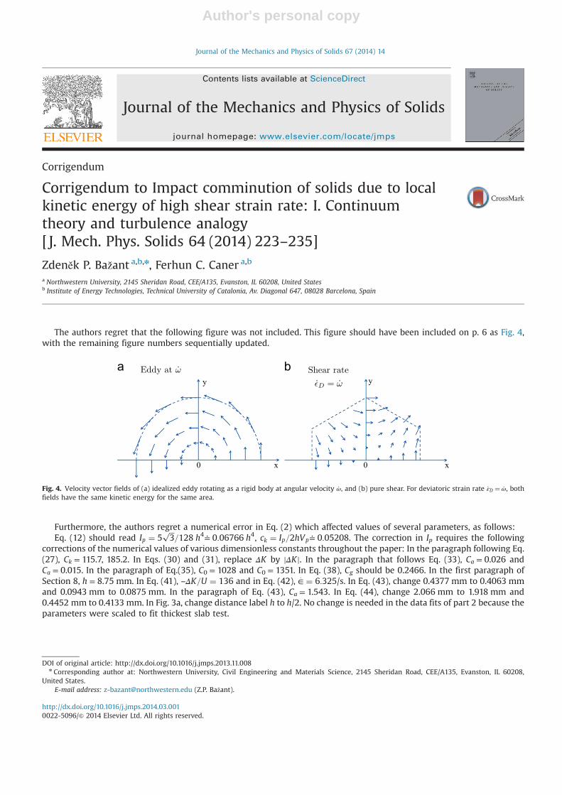
The authors regret that the following figure was not included. This figure should have been included on p. 6 as Fig. 4,with the remaining figure numbers sequentially updated.
Furthermore, the authors regret a numerical error in Eq. (2) which affected values of several parameters, as follows:Eq. (12) should read Ip ¼ 5
ffiffiffi3
p=128 h4≐ 0:06766 h4, ck ¼ Ip=2hVp≐ 0:05208. The correction in Ip requires the following
corrections of the numerical values of various dimensionless constants throughout the paper: In the paragraph following Eq.(27), Ck = 115.7, 185.2. In Eqs. (30) and (31), replace ΔK by jΔKj. In the paragraph that follows Eq. (33), Ca = 0.026 andCa = 0.015. In the paragraph of Eq.(35), C0 = 1028 and C0 = 1351. In Eq. (38), Cg should be 0.2466. In the first paragraph ofSection 8, h = 8.75 mm. In Eq. (41), –ΔK=U ¼ 136 and in Eq. (42), ∈
: ¼ 6:325/s. In Eq. (43), change 0.4377 mm to 0.4063 mmand 0.0943 mm to 0.0875 mm. In the paragraph of Eq. (43), Ca = 1.543. In Eq. (44), change 2.066 mm to 1.918 mm and0.4452 mm to 0.4133 mm. In Fig. 3a, change distance label h to h/2. No change is needed in the data fits of part 2 because theparameters were scaled to fit thickest slab test.
Contents lists available at ScienceDirect
journal homepage: www.elsevier.com/locate/jmps
Journal of the Mechanics and Physics of Solids
0 x
y
0 x
y
Fig. 4. Velocity vector fields of (a) idealized eddy rotating as a rigid body at angular velocity _ω, and (b) pure shear. For deviatoric strain rate _εD ¼ _ω, bothfields have the same kinetic energy for the same area.
http://dx.doi.org/10.1016/j.jmps.2014.03.0010022-5096/& 2014 Elsevier Ltd. All rights reserved.
DOI of original article: http://dx.doi.org/10.1016/j.jmps.2013.11.008n Corresponding author at: Northwestern University, Civil Engineering and Materials Science, 2145 Sheridan Road, CEE/A135, Evanston, IL 60208,
United States.E-mail address: [email protected] (Z.P. Bažant).
Journal of the Mechanics and Physics of Solids 67 (2014) 14
Contents lists available at ScienceDirect
Journal of the Mechanics and Physics of Solids
Journal of the Mechanics and Physics of Solids 64 (2014) 236–248
0022-50http://d
n CorrE-m1 As
Enginee2 M
journal homepage: www.elsevier.com/locate/jmps
Impact comminution of solids due to local kinetic energy ofhigh shear strain rate: II—Microplane model and verification
Ferhun C. Caner a,1, Zdeněk P. Bažant b,n,2
a Institute of Energy Technologies, Technical University of Catalonia, Av. Diagonal 647, 08028 Barcelona, Spainb Northwestern University, 2145 Sheridan Road, CEE/A135, Evanston, IL 60208, United States
a r t i c l e i n f o
Article history:Received 21 July 2013Received in revised form11 November 2013Accepted 13 November 2013Available online 26 November 2013
Keywords:Fracture mechanicsDynamic fractureComminutionConstitutive modellingConcrete
96/$ - see front matter & 2014 Published byx.doi.org/10.1016/j.jmps.2013.11.009
esponding author. Tel.: þ1 847 491 4025; faail addresses: [email protected] (F.C. Cansociate Professor at the Institute of Energring, Northwestern University.cCormick Institute Professor and W.P. Murp
a b s t r a c t
The new theory presented in the preceding paper, which models the dynamic comminu-tion of concrete due to very high shear strain rate, is now compared to recent test data onthe penetration of projectiles through concrete walls of different thicknesses, rangingfrom 127 to 254 mm. These data are analyzed by an explicit finite element code using thenew microplane constitutive model M7 for concrete, which was previously shown toprovide the most realistic description of the quasi-static uni-, bi- and tri-axial test datawith complex loading path and unloading. Model M7 incorporates the quasi-static strainrate effects due viscoelasticity and to the rate of cohesive crack debonding based onactivation energy of bond ruptures, which are expected to extend to very high rates. Heremodel M7 is further enhanced by apparent viscosity capturing the energy dissipationdue to the strain-rate effect of comminution. The maximum shear strain rates in thecomputations are of the order of 105 s�1. The simulations document that, within theinevitable uncertainties, the measured exit velocities of the projectiles can be matchedquite satisfactorily and the observed shapes of the entry and exit craters can bereproduced correctly.
& 2014 Published by Elsevier Ltd.
1. Introduction
The preceding Part 1 (Bažant and Caner, this issue) presented a new theory that allows the energy dissipation due todynamic comminution of material under impact to be modeled through the constitutive relation which can be readilyimplemented in standard finite element programs. The comminution is assumed to be driven by the release of local kineticenergy of high shear strain rate caused by impact, and the energy dissipation due to comminution and inter-particle slip ismodeled by additional apparent viscosity.
In the present part 2, the theory is being applied to the problem of penetration of missiles through concrete walls ofvarious thicknesses. Fitting of previously published impact test data is used to calibrate and validate the new theory.
Because of the complexity of triaxial softening damage in concrete, the microplane model is selected as the constitutivelaw, to be enriched by the comminution rate effect. The microplane model has already been used with great success for thesimulations of various dynamic effects on hardened concrete structures, including the effects of explosions, impact and
Elsevier Ltd.
x: þ1 847 491 4011.er), [email protected] (Z.P. Bažant).y Technologies, Technical University of Catalonia and Visiting Scholar at Dept. of Civil and Env.
hy Professor of Civil Engineering and Materials Science.
F.C. Caner, Z.P. Bažant / J. Mech. Phys. Solids 64 (2014) 236–248 237
groundshock. In contrast to plastic and other tensorial constitutive models, various microplane models have been showncapable of predicting the correct entry and exit crater shapes of penetrating missiles (Bažant et al., 2000a; Adley et al., 2012).
However, prediction of the exit velocities of perforating projectiles proved to be much more challenging. Recently a newmodel based on the microplane model M4, called the high-rate brittle microplane model, has been developed at U.S. ArmyCorps of Engineers (Adley et al., 2012). To fit the exit velocities, the microplane stress–strain boundaries (i.e., strain-dependent yield limits) were scaled up drastically, both vertically and horizontally, as functions of the strain rate (Adleyet al., 2012). But the scaling ratios were empirical, with no theory behind them. Their empirical nature unfortunatelysevered the connection to the numerous types of static uni-, bi-, and tri-axial tests by which M4 was calibrated. Besides, inthe sense of crack-band or nonlocal concept, the model in Adley et al. (2012) implied a major increase of fracture energy,while the previous studies showed the fracture energy to be only weakly dependent on the strain rate. This study will showthat an extended microplane model, labeled M7R, which incorporates the theory of material comminution expounded inPart I, can fit the exit velocities satisfactorily without loosing the capability to fit all the static tests.
2. Review of microplane model and its version M7
The internal friction in materials is usually modeled as a relation between the first stress invariant and the seconddeviator invariant, without any reference to the direction of slip. This is not realistic. The plastic or frictional slip occurs infact only on planes of a certain specific orientation. Likewise, almost all of the other inelastic deformations in concretemicrostructure, such as tensile cracking and compressive axial splitting, occur on planes of well defined orientations. Theseorientations can be captured by the idea of Taylor (1938) who proposed to formulate the constitutive law in terms ofthe vectors of stress and strain acting on planes of various orientations in the material. This idea was first developed forplasticity of polycrystalline metals under the name of slip theory of plasticity (Batdorf and Budianski, 1949) and has by nowled to powerful plasticity models called the Taylor models (Butler and McDowell, 1998; Rice, 1971). In these models, thestress vectors on the slip planes are the projections of the continuum stress tensor, which is called the static constraint, andthe plastic slips on all the slip planes are simply superposed.
In the early 1980s, it was realized (Bažant, 1984; Bažant and Oh, 1985) that Taylor models are unstable in the case ofstrain-softening damage due to diffuse microcracking. To ensure model stability, the static constraint had to be changed tothe kinematic constraint, in which the strain vector is the projection of the strain tensor onto a generic plane in themicrostructure, called the microplane. Also the elastic deformation had to be included on the microplane level. The staticequivalence of the stress tensor with stress vectors on microplanes of all possible spatial orientations was enforced by theprinciple of virtual work, which gives the continuum stress tensor
sij ¼32π
ZΩ
sNNijþsLLijþsMMij� �
dΩ ð1Þ
This is an integral over a unit hemisphere Ω, in which sij¼stress tensor, sN ; sL; sM ¼ normal and two shear components ofthe microplane stress vector, and Nij; Lij;Mij ¼ geometrical coefficients defined later. This integral is evaluated approximatelyaccording to an optimum Gaussian integration formula as a weighted sum over all the discrete microplanes whose normalsare chosen to correspond to the integration points of this formula.
Compared to the classical tensorial constitutive models based on tensorial invariants, the microplane concept has a numberof advantages: (1) It is conceptually simpler, since the strain vectors on the microplanes can be intuitively related to crackopening and slip. (2) The orientation of cracking and slip can be captured. (3) The so-called vertex effect is automatic, whilebeing beyond the capability of the tensorial constitutive models. (4) Apparent deviations from normality in the sense oftensorial plasticity models are represented, thanks to the fact that the microplane model is equivalent to a large set ofsimultaneously active yield surfaces intersecting at the same point of the stress space, for each of which the normality rule canbe satisfied (this is particularly important for dynamic loading, with highly nonproportional loading paths). (5) The kinematicconstraint of the microplanes of different orientation automatically simulates the cross effects such as the shear dilatancy andpressure sensitivity. (6) Combinations of loading and unloading on different microplanes provide a complex path dependenceand automatically reproduce the Bauschinger effect and the hysteresis under cyclic loading. (7) The dependence of the currentyield or strength limits on the strain components (rather than on scalar hardening–softening parameters) is easy to take intoaccount. (8) In cyclic loading, fatigue is automatically simulated by accumulation of residual stresses on the microplanes aftereach load cycle. (9) Finally, though not important for concrete, anisotropy can be easily captured.
Early on, the microplane model was computationally too demanding for full structures. But thanks to the rise ofcomputer power, the microplane model is now being used in systems with tens of millions finite elements. Manyprogressively improved versions of the microplane model, now labeled M1, M2,…,M7, have been developed for concrete,and so have other variants for fiber-reinforced concrete, fiber–polymer composites, sandstone, shale, clay, rigid foam, shapememory alloy and some soft tissues. Model M4 (Bažant et al., 2000b; Caner and Bažant, 2000) was used with success inlarge-scale simulation of various explosions and groundshock, and with partial success in missile impact and penetration ofconcrete walls. The new model M7 (Caner and Bažant, 2013a,b), used and refined in this work, brings about furthersignificant improvements. It eliminates unrealistic lateral strains in postpeak tensile softening, gives damage dependentunloading and works even for cyclic loading with softening.
F.C. Caner, Z.P. Bažant / J. Mech. Phys. Solids 64 (2014) 236–248238
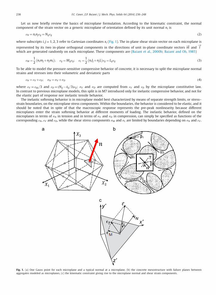
Let us now briefly review the basics of microplane formulation. According to the kinematic constraint, the normalcomponent of the strain vector on a generic microplane of orientation defined by its unit normal ni is
εN ¼ ninjεij ¼Nijεij ð2Þ
where subscripts i; j¼ 1;2;3 refer to Cartesian coordinates xi (Fig. 1). The in-plane shear strain vector on each microplane is
represented by its two in-plane orthogonal components in the directions of unit in-plane coordinate vectors m! and l!
which are generated randomly on each microplane. These components are (Bažant et al., 2000b; Bažant and Oh, 1985)
εM ¼ 12
nimjþnjmi� �
; εij ¼Mijεij; εL ¼12
niljþnjli� �
εij ¼ Lijεij ð3Þ
To be able to model the pressure-sensitive compressive behavior of concrete, it is necessary to split the microplane normalstrains and stresses into their volumetric and deviatoric parts
εN ¼ εV þεD; sN ¼ sV þsD ð4Þ
where εV ¼ εkk=3 and εD ¼ ðNij�δij=3Þεij; sV and sD are computed from εV and εD by the microplane constitutive law.In contrast to previous microplane models, this split is in M7 introduced only for inelastic compressive behavior, and not forthe elastic part of response nor inelastic tensile behavior.
The inelastic softening behavior is in microplane model best characterized by means of separate strength limits, or stress–strain boundaries, on the microplane stress components. Within the boundaries, the behavior is considered to be elastic, and itshould be noted that in spite of that the macroscopic response represents the pre-peak nonlinearity because differentmicroplanes enter the strain softening behavior at different moments of loading. The inelastic behavior, defined on themicroplanes in terms of sN in tension and in terms of sV and sD in compression, can simply be specified as functions of thecorresponding εN , εV and εD, while the shear stress components sM and sL are limited by boundaries depending on sN and εV .
Fig. 1. (a) One Gauss point for each microplane and a typical normal at a microplane, (b) the concrete mesostructure with failure planes betweenaggregates modeled as microplanes, (c) the kinematic constraint giving rise to the microplane normal and shear strain components.
F.C. Caner, Z.P. Bažant / J. Mech. Phys. Solids 64 (2014) 236–248 239
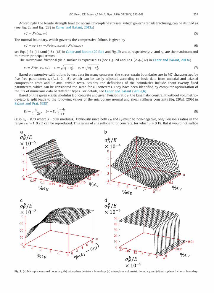
Accordingly, the tensile strength limit for normal microplane stresses, which governs tensile fracturing, can be defined as(see Fig. 2a and Eq. (23) in Caner and Bažant, 2013a)
sþN ¼FNðεN ; sV Þ ð5Þ
The normal boundary, which governs the compressive failure, is given by
s�N ¼ sV þsD ¼FV ðεV ; εI ; εIIIÞþFDðεD; εV Þ ð6Þ
see Eqs. (13)–(14) and (16)–(18) in Caner and Bažant (2013a), and Fig. 2b and c, respectively; εI and εIII are the maximum andminimum principal strains.
The microplane frictional yield surface is expressed as (see Fig. 2d and Eqs. (26)–(32) in Caner and Bažant, 2013a)
sτ ¼F T ðετ; εV ; sNÞ; ετ ¼ffiffiffiffiffiffiffiffiffiffiffiffiffiffiffiε2L þε2M
q; sτ ¼
ffiffiffiffiffiffiffiffiffiffiffiffiffiffiffiffis2L þs2M
qð7Þ
Based on extensive calibrations by test data for many concretes, the stress–strain boundaries are in M7 characterized byfive free parameters ki (i¼1, 2,…,5), which can be easily adjusted according to basic data from uniaxial and triaxialcompression tests and uniaxial tensile tests. Besides, the definitions of the boundaries include about twenty fixedparameters, which can be considered the same for all concretes. They have been identified by computer optimization ofthe fits of numerous data of different types. For details, see Caner and Bažant (2013a,b).
Based on the given elastic modulus E of concrete and given Poisson ratio ν, the kinematic constraint without volumetric–deviatoric split leads to the following values of the microplane normal and shear stiffness constants (Eq. (20a), (20b) inBažant and Prat, 1988)
EN ¼ E1�2ν
; ET ¼ EN1�4ν1þν
ð8Þ
(also EN ¼ K=3 where K¼bulk modulus). Obviously since both EN and ET must be non-negative, only Poisson's ratios in therange νA ½�1;0:25� can be reproduced. This range of ν is sufficient for concrete, for which ν� 0:18. But it would not suffice
Fig. 2. (a) Microplane normal boundary, (b) microplane deviatoric boundary, (c) microplane volumetric boundary and (d) microplane frictional boundary.
F.C. Caner, Z.P. Bažant / J. Mech. Phys. Solids 64 (2014) 236–248240
for a general material, for which νA ½�1; 0:5�. In that case, to get the full range of ν, the microplane model M7 must becoupled in series with an isotropic shear-deformable elastic element of an infinite bulk modulus K′¼1 and a finite shearmodulus G′40 (Bažant and Oh, 1985) (see Fig. 2 in Caner and Bažant, 2013a; Caner et al., 2013).
The thermodynamic requirement of non-negative density of energy dissipation is discussed in detail in Caner and Bažant(2013a).
3. Calibration of model M7 by WES-5000 test data
Numerous earth penetration simulations in the literature have used the Eulerian coordinates, which are the coordinatesof the current state and do not allow keeping the memory of the initial virgin state of the material. This approach is suitablefor plastic materials. However, for brittle or quasibrittle materials, and particularly for the microplane model of concrete,memory of the initial virgin state is essential. Therefore, the updated Lagrangian approach, in which the material points arecharacterized by their coordinates in the initial state, must be used. Calculations show that the predicted geometry of theexit crater, as well as the deceleration of projectile prior to exit, depend strongly on the softening damage behavior of thematerial, whose characterization depends on the initial virgin state.
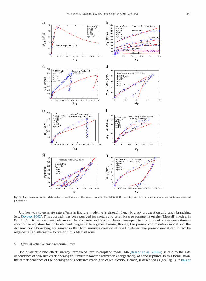
Given the complexity of concrete behavior, the constitutive law has been verified against a large set of experimental datacovering virtually all the distinct types of experiments that characterize concrete, whose number is about 20 (Caner andBažant, 2013b). A complicating feature of verification is that the test data used to verify Model M7 were obtained bynumerous researchers in different laboratories, using different concretes. For calibration of model M7 for WES-5000concrete, not only classical laboratory test data such as uniaxial and triaxial compression data, but also the test dataobtained under unconventional loading paths (Cargile, 1999) have been employed, as shown in Fig. 3.
The same free model parameters, namely E¼25 GPa, k1 ¼ 11� 10�5, k2 ¼ 110, k3 ¼ 30, k4 ¼ 100 and k5 ¼ 1� 10�4, havebeen used for all the present data fits. Although in two cases the simulations show significant differences from the test data,the fit of a great majority of the simulations is good. Model M7 has also been verified by comparisons with the tests ofcompression–tension load cycles, the tests of mixed-mode crack propagation (see Figs. 4, 5, 6 and 7 in Caner and Bažant,2013b), and the tests of explosions on plain concrete slabs.
The fits are performed by taking into account the meaning of the coefficients in terms of various particular aspects of themechanical behavior of concrete. This kind of fitting procedure is more tedious than the automatic procedures such as theLevenberg–Marquardt optimization algorithm or the genetic algorithm but the resulting optimum values of the parameterpreserve the robustness of the model in simulating general stress states. Complex automatic fitting procedures often yieldparameter values that correspond to very close fits but almost always such parameter values render the model unstable insimulations of multiaxial states of stress. This is because it is not entirely possible to convey the meaning of each modelparameter to the automatic fitting procedure.
4. Data from missile penetration tests
Slabs made of normal strength concrete, called the WES-5000 concrete, were perforated by projectiles at theGeotechnical and Structures Laboratory of the U.S. Army Engineer Research and Development Center (ERDC), Vicksburg(Frank et al., 2012). The slabs were circular, of thicknesses of 127, 216 and 254 mm, and were cast in steel culvert pipes ofdiameter of 1.52 m, two or three slabs for each thickness. The exit velocities were averaged. The projectiles had an ogivenose, weighed 2.3 kg and hit the slab with the entry velocity of 310 m/s and at an impact angle of 901 (with deviations ofo11). The measured exit velocities of the projectiles were 225 m/s, 115 m/s and 45 m/s for the three slab thicknesses,respectively (Frank et al., 2012; Cargile, 1999). The geometries of the entry and exit craters were determined after the tests.Slabs of three different thicknesses were penetrated. As seen in finite element simulations, the strain rates in the thinnestslabs remained very high throughout the entire duration of the penetration. In the thickest slabs, the strain rates were veryhigh initially but became only moderately high later on.
To obtain material data, standard cylindrical specimens of the same WES-5000 concrete were tested under bothconventional and unconventional triaxial load paths (Caner and Bažant, 2000, 2013a). Frank et al. (2012). Various materialmodels were calibrated with these quasistatic test data, and subsequently used to calculate the exit velocities as well as theentry and exit crater shapes in all three slabs. Despite using a variety of models, it turned out to be very challenging to matchthe test results (Frank et al., 2012).
5. Quasi-static rate effect in Model M7
As is clear from the preceding Part I (Bažant and Caner, this issue), there are two kinds of deformation rate effects—quasistatic and comminutive. The quasistatic rate effects are expected on theoretical grounds to extend to extreme rates andso they must be part of the material model even for such rates. Besides, even in projectile impact and perforation, the zonesfarther away from the missile are not deforming at extreme rates and exhibit only the quasistatic rate effects which play arole in wave attenuation and diffraction, and the same is true when the projectile forms the exit crater at greatly reducedvelocity.
(MP
a)
(MP
a)
(MP
a)
(MP
a)
(MP
a)
(MP
a)
(MP
a)
(MP
a)
Fig. 3. Benchmark set of test data obtained with one and the same concrete, the WES-5000 concrete, used to evaluate the model and optimize materialparameters.
F.C. Caner, Z.P. Bažant / J. Mech. Phys. Solids 64 (2014) 236–248 241
Another way to generate rate effects in fracture modeling is through dynamic crack propagation and crack branching(e.g. Doyoyo, 2002). This approach has been pursued for metals and ceramics (see comments on the “Mescall” models inPart I). But it has not been elaborated for concrete and has not been developed in the form of a macro-continuumconstitutive equation for finite element programs. In a general sense, though, the present comminution model and thedynamic crack branching are similar in that both simulate creation of small particles. The present model can in fact beregarded as an alternative to creation of a Mescall zone.
5.1. Effect of cohesive crack separation rate
One quasistatic rate effect, already introduced into microplane model M4 (Bažant et al., 2000a), is due to the ratedependence of cohesive crack opening w. It must follow the activation energy theory of bond ruptures. In this formulation,the rate dependence of the opening w of a cohesive crack (also called ‘fictitious’ crack) is described as (see Fig. 1a in Bažant
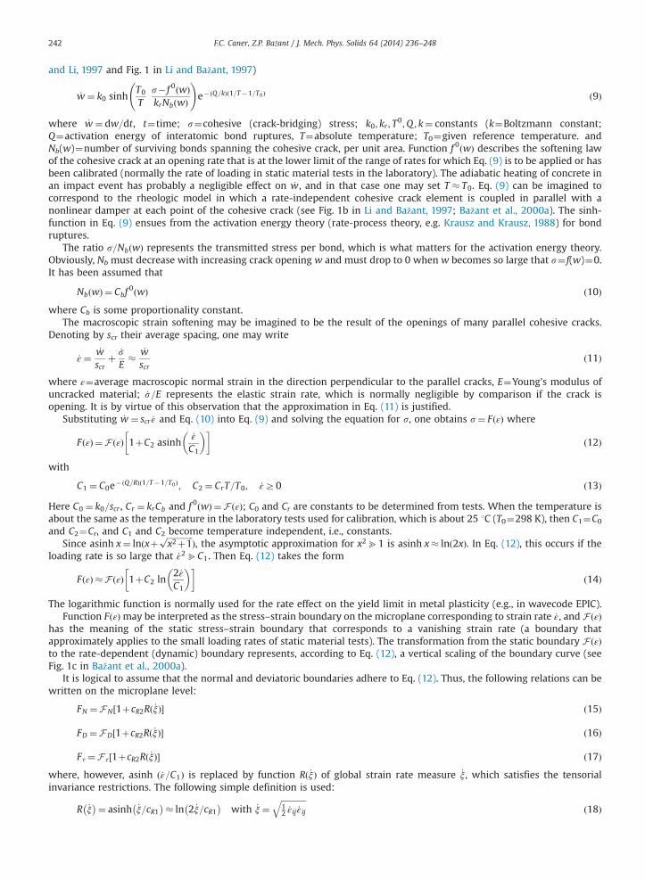
F.C. Caner, Z.P. Bažant / J. Mech. Phys. Solids 64 (2014) 236–248242
and Li, 1997 and Fig. 1 in Li and Bažant, 1997)
_w ¼ k0 sinhT0
Ts� f 0ðwÞkrNbðwÞ
!e�ðQ=kÞð1=T�1=T0Þ ð9Þ
where _w ¼ dw=dt, t¼time; s¼cohesive (crack-bridging) stress; k0; kr ; T0;Q ; k¼ constants (k¼Boltzmann constant;
Q¼activation energy of interatomic bond ruptures, T¼absolute temperature; T0¼given reference temperature. andNb(w)¼number of surviving bonds spanning the cohesive crack, per unit area. Function f 0ðwÞ describes the softening lawof the cohesive crack at an opening rate that is at the lower limit of the range of rates for which Eq. (9) is to be applied or hasbeen calibrated (normally the rate of loading in static material tests in the laboratory). The adiabatic heating of concrete inan impact event has probably a negligible effect on _w, and in that case one may set T � T0. Eq. (9) can be imagined tocorrespond to the rheologic model in which a rate-independent cohesive crack element is coupled in parallel with anonlinear damper at each point of the cohesive crack (see Fig. 1b in Li and Bažant, 1997; Bažant et al., 2000a). The sinh-function in Eq. (9) ensues from the activation energy theory (rate-process theory, e.g. Krausz and Krausz, 1988) for bondruptures.
The ratio s=NbðwÞ represents the transmitted stress per bond, which is what matters for the activation energy theory.Obviously, Nb must decrease with increasing crack opening w and must drop to 0 when w becomes so large that s¼ f(w)¼0.It has been assumed that
NbðwÞ ¼ Cbf0ðwÞ ð10Þ
where Cb is some proportionality constant.The macroscopic strain softening may be imagined to be the result of the openings of many parallel cohesive cracks.
Denoting by scr their average spacing, one may write
_ε ¼ _wscr
þ _sE� _w
scrð11Þ
where ε¼average macroscopic normal strain in the direction perpendicular to the parallel cracks, E¼Young's modulus ofuncracked material; _s=E represents the elastic strain rate, which is normally negligible by comparison if the crack isopening. It is by virtue of this observation that the approximation in Eq. (11) is justified.
Substituting _w ¼ scr _ε and Eq. (10) into Eq. (9) and solving the equation for s, one obtains s¼ FðεÞ where
F εð Þ ¼F εð Þ 1þC2 asinh_ε
C1
� �� �ð12Þ
with
C1 ¼ C0e�ðQ=RÞð1=T�1=T0Þ; C2 ¼ CrT=T0; _εZ0 ð13Þ
Here C0 ¼ k0=scr , Cr ¼ krCb and f 0ðwÞ ¼F ðεÞ; C0 and Cr are constants to be determined from tests. When the temperature isabout the same as the temperature in the laboratory tests used for calibration, which is about 25 1C (T0¼298 K), then C1¼C0and C2¼Cr, and C1 and C2 become temperature independent, i.e., constants.
Since asinh x¼ lnðxþffiffiffiffiffiffiffiffiffiffiffiffiffix2þ1
pÞ, the asymptotic approximation for x2b1 is asinh x� lnð2xÞ. In Eq. (12), this occurs if the
loading rate is so large that _ε2bC1. Then Eq. (12) takes the form
F εð Þ �F εð Þ 1þC2 ln2_εC1
� �� �ð14Þ
The logarithmic function is normally used for the rate effect on the yield limit in metal plasticity (e.g., in wavecode EPIC).Function FðεÞmay be interpreted as the stress–strain boundary on the microplane corresponding to strain rate _ε, and F ðεÞ
has the meaning of the static stress–strain boundary that corresponds to a vanishing strain rate (a boundary thatapproximately applies to the small loading rates of static material tests). The transformation from the static boundary F ðεÞto the rate-dependent (dynamic) boundary represents, according to Eq. (12), a vertical scaling of the boundary curve (seeFig. 1c in Bažant et al., 2000a).
It is logical to assume that the normal and deviatoric boundaries adhere to Eq. (12). Thus, the following relations can bewritten on the microplane level:
FN ¼FN½1þcR2Rð_ξÞ� ð15Þ
FD ¼FD½1þcR2Rð_ξÞ� ð16Þ
Fτ ¼F τ½1þcR2Rð_ξÞ� ð17Þwhere, however, asinh ð_ε=C1Þ is replaced by function Rð_ξÞ of global strain rate measure _ξ, which satisfies the tensorialinvariance restrictions. The following simple definition is used:
R _ξ� �¼ asinh _ξ=cR1
� �� ln 2_ξ=cR1� �
with _ξ ¼ffiffiffiffiffiffiffiffiffiffiffiffi12 _ε ij _ε ij
qð18Þ
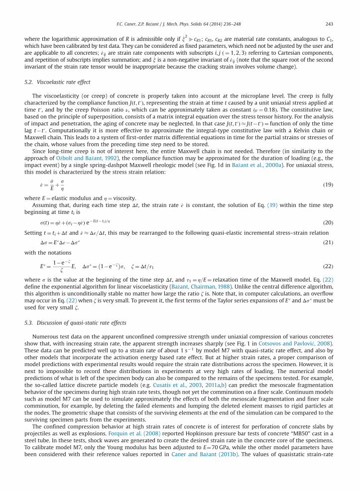
F.C. Caner, Z.P. Bažant / J. Mech. Phys. Solids 64 (2014) 236–248 243
where the logarithmic approximation of R is admissible only if _ξ2bcR1; cR1, cR2 are material rate constants, analogous to C1,
which have been calibrated by test data. They can be considered as fixed parameters, which need not be adjusted by the user andare applicable to all concretes; _ε ij are strain rate components with subscripts i; j ð ¼ 1;2;3Þ referring to Cartesian components,and repetition of subscripts implies summation; and _ξ is a non-negative invariant of _εij (note that the square root of the secondinvariant of the strain rate tensor would be inappropriate because the cracking strain involves volume change).
5.2. Viscoelastic rate effect
The viscoelasticity (or creep) of concrete is properly taken into account at the microplane level. The creep is fullycharacterized by the compliance function Jðt; t′Þ, representing the strain at time t caused by a unit uniaxial stress applied attime t′, and by the creep Poisson ratio ν, which can be approximately taken as constant ðν¼ 0:18Þ. The constitutive law,based on the principle of superposition, consists of a matrix integral equation over the stress tensor history. For the analysisof impact and penetration, the aging of concrete may be neglected. In that case Jðt; t′Þ � Jðt�t′Þ ¼ function of only the timelag t�t′. Computationally it is more effective to approximate the integral-type constitutive law with a Kelvin chain orMaxwell chain. This leads to a system of first-order matrix differential equations in time for the partial strains or stresses ofthe chain, whose values from the preceding time step need to be stored.
Since long-time creep is not of interest here, the entire Maxwell chain is not needed. Therefore (in similarity to theapproach of Ožbolt and Bažant, 1992), the compliance function may be approximated for the duration of loading (e.g., theimpact event) by a single spring-dashpot Maxwell rheologic model (see Fig. 1d in Bažant et al., 2000a). For uniaxial stress,this model is characterized by the stress strain relation:
_ε ¼ _sEþ s
ηð19Þ
where E¼ elastic modulus and η¼ viscosity.Assuming that, during each time step Δt, the strain rate _ε is constant, the solution of Eq. (19) within the time step
beginning at time ti is
sðtÞ ¼ η_εþðsi�η_εÞ e�Eðt� tiÞ=η ð20ÞSetting t ¼ tiþΔt and _ε �Δε=Δt, this may be rearranged to the following quasi-elastic incremental stress–strain relation
Δs¼ E″Δε�Δs″ ð21Þwith the notations
E″¼ 1�e� ζ
ζE; Δs″¼ 1�e� ζ
� �s; ζ¼Δt=τ1 ð22Þ
where s is the value at the beginning of the time step Δt, and τ1 ¼ η=E¼ relaxation time of the Maxwell model. Eq. (22)define the exponential algorithm for linear viscoelasticity (Bažant, Chairman, 1988). Unlike the central difference algorithm,this algorithm is unconditionally stable no matter how large the ratio ζ is. Note that, in computer calculations, an overflowmay occur in Eq. (22) when ζ is very small. To prevent it, the first terms of the Taylor series expansions of E″ and Δs″must beused for very small ζ.
5.3. Discussion of quasi-static rate effects
Numerous test data on the apparent unconfined compressive strength under uniaxial compression of various concretesshow that, with increasing strain rate, the apparent strength increases sharply (see Fig. 1 in Cotsovos and Pavlović, 2008).These data can be predicted well up to a strain rate of about 1 s�1 by model M7 with quasi-static rate effect, and also byother models that incorporate the activation energy based rate effect. But at higher strain rates, a proper comparison ofmodel predictions with experimental results would require the strain rate distributions across the specimen. However, it isnext to impossible to record these distributions in experiments at very high rates of loading. The numerical modelpredictions of what is left of the specimen body can also be compared to the remains of the specimens tested. For example,the so-called lattice discrete particle models (e.g. Cusatis et al., 2003, 2011a,b) can predict the mesoscale fragmentationbehavior of the specimens during high strain rate tests, though not yet the comminution on a finer scale. Continuum modelssuch as model M7 can be used to simulate approximately the effects of both the mesoscale fragmentation and finer scalecomminution, for example, by deleting the failed elements and lumping the deleted element masses to rigid particles atthe nodes. The geometric shape that consists of the surviving elements at the end of the simulation can be compared to thesurviving specimen parts from the experiments.
The confined compression behavior at high strain rates of concrete is of interest for perforation of concrete slabs byprojectiles as well as explosions. Forquin et al. (2008) reported Hopkinson pressure bar tests of concrete “MB50” cast in asteel tube. In these tests, shock waves are generated to create the desired strain rate in the concrete core of the specimens.To calibrate model M7, only the Young modulus has been adjusted to E¼70 GPa, while the other model parameters havebeen considered with their reference values reported in Caner and Bažant (2013b). The values of quasistatic strain-rate

F.C. Caner, Z.P. Bažant / J. Mech. Phys. Solids 64 (2014) 236–248244
parameters were determined as CR1 ¼ 4� 10�6 and CR2 ¼ 0:022. Fig. 4a depicts the hoop strain test data measured by straingauge G3 and their predictions by model M7. The predictions by model M7 are completely satisfactory.
Next, using model M7 calibrated for the “MB50” concrete used in these tests, the axial stress–strain response of thatconcrete to high strain rates is extracted, as shown in Fig. 4b. The responses for the strain rates 141 s�1 and 221 s�1 arevisually indistinguishable, meaning the continuous curve in that figure is probably the maximum response that can beobtained for such concretes cast in steel tubes using the activation energy based rate effect theory. The dashed curve in thisfigure corresponds to quasi-static laboratory strain rates. These results indicate that, when the inertial effects are minimized,a relatively small strain rate effect exists in the response of concrete under confinement even when the strain rates aresignificantly larger than the quasi-static rates.
6. Comminution rate effect in model M7 and simulations of missile penetration
The sharp increase of the strength amplification factor for strain rates above 10 s�1 (e.g. see Fig. 1 in Cotsovos andPavlović, 2008 or Fig. 1 in Bažant and Caner, this issue) documents that good prediction of the exit velocities of projectiles ishardly possible using only quasi-static strain rate effects. This is documented by Fig. 3 showing the calculation results formicroplane model M7 calibrated for the WES-5000 concrete. To resolve the strain rates and keep the discretization errorlow, small enough tetrahedral elements (of size 7.5 mm) have been employed in the finite element analyses. Both thecompression and tension performance of these elements employing the M7 constitutive model have been verified.
A series of finite element calculations of projectile perforation have been performed using model M7 with only the quasi-static strain rate effects. The results are shown as the dashed curve in Fig. 5. The calculated exit velocities far exceed theexperimental values. Thus, the quasi-static rate effects are clearly insufficient to explain the observed exit velocities of theseprojectiles.
It should be mentioned that these velocities could roughly be obtained by calculations with an enhanced frictioncoefficient. However, assuming a higher friction coefficient for high slip rates is questionable since other experimental
Fig. 4. (a) Comparison of hoop strain test data at strain rates of 80 s�1 and 221 s�1 of MB50 concrete cast in steel tubes (symbols) and predictions by themodel M7 (lines); (b) axial stress–strain behavior of MB50 concrete at quasistatic strain rates (dashed line) and at a strain rate of 221 s�1 (continuous line).
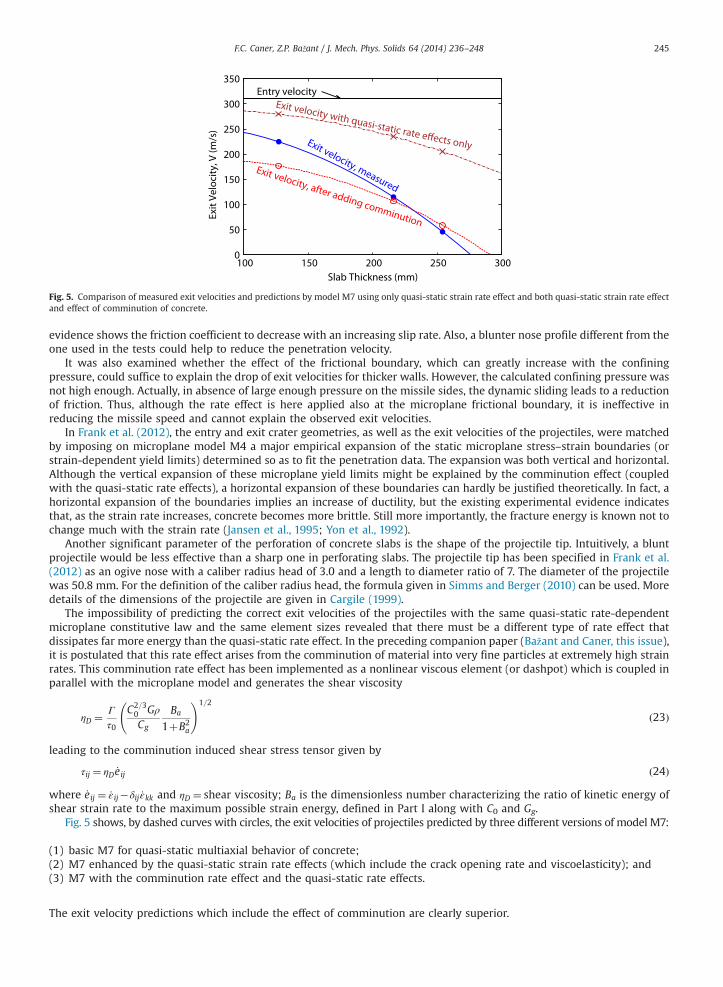
0
50
100
150
200
250
300
350
100 150 200 250 300
Exit
Vel
ocit
y, V
(m/s
)
Slab Thickness (mm)
Entry velocityExit velocity with quasi-static rate effects onlyExit velocity, measured
Exit velocity, after adding comminution
Fig. 5. Comparison of measured exit velocities and predictions by model M7 using only quasi-static strain rate effect and both quasi-static strain rate effectand effect of comminution of concrete.
F.C. Caner, Z.P. Bažant / J. Mech. Phys. Solids 64 (2014) 236–248 245
evidence shows the friction coefficient to decrease with an increasing slip rate. Also, a blunter nose profile different from theone used in the tests could help to reduce the penetration velocity.
It was also examined whether the effect of the frictional boundary, which can greatly increase with the confiningpressure, could suffice to explain the drop of exit velocities for thicker walls. However, the calculated confining pressure wasnot high enough. Actually, in absence of large enough pressure on the missile sides, the dynamic sliding leads to a reductionof friction. Thus, although the rate effect is here applied also at the microplane frictional boundary, it is ineffective inreducing the missile speed and cannot explain the observed exit velocities.
In Frank et al. (2012), the entry and exit crater geometries, as well as the exit velocities of the projectiles, were matchedby imposing on microplane model M4 a major empirical expansion of the static microplane stress–strain boundaries (orstrain-dependent yield limits) determined so as to fit the penetration data. The expansion was both vertical and horizontal.Although the vertical expansion of these microplane yield limits might be explained by the comminution effect (coupledwith the quasi-static rate effects), a horizontal expansion of these boundaries can hardly be justified theoretically. In fact, ahorizontal expansion of the boundaries implies an increase of ductility, but the existing experimental evidence indicatesthat, as the strain rate increases, concrete becomes more brittle. Still more importantly, the fracture energy is known not tochange much with the strain rate (Jansen et al., 1995; Yon et al., 1992).
Another significant parameter of the perforation of concrete slabs is the shape of the projectile tip. Intuitively, a bluntprojectile would be less effective than a sharp one in perforating slabs. The projectile tip has been specified in Frank et al.(2012) as an ogive nose with a caliber radius head of 3.0 and a length to diameter ratio of 7. The diameter of the projectilewas 50.8 mm. For the definition of the caliber radius head, the formula given in Simms and Berger (2010) can be used. Moredetails of the dimensions of the projectile are given in Cargile (1999).
The impossibility of predicting the correct exit velocities of the projectiles with the same quasi-static rate-dependentmicroplane constitutive law and the same element sizes revealed that there must be a different type of rate effect thatdissipates far more energy than the quasi-static rate effect. In the preceding companion paper (Bažant and Caner, this issue),it is postulated that this rate effect arises from the comminution of material into very fine particles at extremely high strainrates. This comminution rate effect has been implemented as a nonlinear viscous element (or dashpot) which is coupled inparallel with the microplane model and generates the shear viscosity
ηD ¼ Γ
τ0
C2=30 GρCg
Ba
1þB2a
!1=2
ð23Þ
leading to the comminution induced shear stress tensor given by
τij ¼ ηD _eij ð24Þ
where _eij ¼ _ε ij�δij _εkk and ηD ¼ shear viscosity; Ba is the dimensionless number characterizing the ratio of kinetic energy ofshear strain rate to the maximum possible strain energy, defined in Part I along with C0 and Gg.
Fig. 5 shows, by dashed curves with circles, the exit velocities of projectiles predicted by three different versions of model M7:
(1)
basic M7 for quasi-static multiaxial behavior of concrete; (2) M7 enhanced by the quasi-static strain rate effects (which include the crack opening rate and viscoelasticity); and (3) M7 with the comminution rate effect and the quasi-static rate effects.The exit velocity predictions which include the effect of comminution are clearly superior.
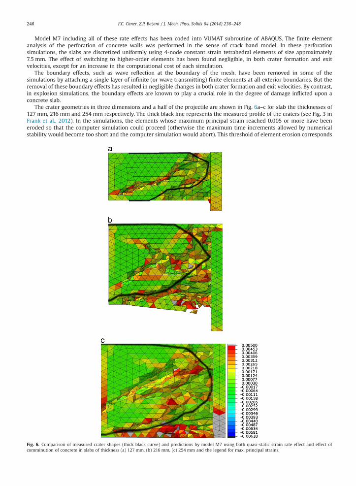
F.C. Caner, Z.P. Bažant / J. Mech. Phys. Solids 64 (2014) 236–248246
Model M7 including all of these rate effects has been coded into VUMAT subroutine of ABAQUS. The finite elementanalysis of the perforation of concrete walls was performed in the sense of crack band model. In these perforationsimulations, the slabs are discretized uniformly using 4-node constant strain tetrahedral elements of size approximately7.5 mm. The effect of switching to higher-order elements has been found negligible, in both crater formation and exitvelocities, except for an increase in the computational cost of each simulation.
The boundary effects, such as wave reflection at the boundary of the mesh, have been removed in some of thesimulations by attaching a single layer of infinite (or wave transmitting) finite elements at all exterior boundaries. But theremoval of these boundary effects has resulted in negligible changes in both crater formation and exit velocities. By contrast,in explosion simulations, the boundary effects are known to play a crucial role in the degree of damage inflicted upon aconcrete slab.
The crater geometries in three dimensions and a half of the projectile are shown in Fig. 6a–c for slab the thicknesses of127 mm, 216 mm and 254 mm respectively. The thick black line represents the measured profile of the craters (see Fig. 3 inFrank et al., 2012). In the simulations, the elements whose maximum principal strain reached 0.005 or more have beeneroded so that the computer simulation could proceed (otherwise the maximum time increments allowed by numericalstability would become too short and the computer simulation would abort). This threshold of element erosion corresponds
Fig. 6. Comparison of measured crater shapes (thick black curve) and predictions by model M7 using both quasi-static strain rate effect and effect ofcomminution of concrete in slabs of thickness (a) 127 mm, (b) 216 mm, (c) 254 mm and the legend for max. principal strains.
F.C. Caner, Z.P. Bažant / J. Mech. Phys. Solids 64 (2014) 236–248 247
to material failure in the direction of the maximum principal strain under quasi-static loading conditions. Failure is assumedeven though some of these eroded elements might still be carrying some compressive stress perpendicular to the maximumtensile stress direction.
7. Uncertainties and errors due to possible effects of moisture content, age, curing, etc.
The overestimation of the exit velocity of the thin slabs might not be an error of the present theory. It might be caused byvarious extraneous factors. For example, since the thinner slabs dry faster, the thin slab must have had a lower specificmoisture content than the thicker one if the curing type and durations were about the same. Hopkinson bar tests reported inCadoni et al. (2001) showed that a lower moisture content of concrete can lead to a significant decrease of strength underhigh-rate loading. This increase might explain why the measured exit velocity for the thin (and thus drier slab) is lower thanthe present prediction shown in Fig. 5. However, the data are so limited that no meaningful calculations are possible at thistime. Especially, it is not clear whether the slab were tested right after moist curing, or whether they were exposed to dryingbefore the test, and whether the period of drying exposure was the same for each slab. The environmental humidity and thepermeability of concrete are also not known.
There are further factors that could have skewed the result. From Cargile (1999) it is not clear whether the specimens hadthe same age at the time of the tests and whether they experienced the same environmental and curing history. Forexample, if the thinner slab was appreciably older than the thicker ones, the chemical process of hydration could havecaused the strength and fracture energy of the thin slabs to be significantly higher than it was in the thicker slabs.Furthermore, according to Cargile (1999), the slabs were clearly not cast from the same batch of concrete, and thus randomdifferences between different batches of the same concrete might have caused strength differences as high as 8%.
So it is at present impossible to conclude whether the overestimation of the exit velocity of the thin plate, seen in Fig. 5,is an error of the present theory, or an error of the data themselves. Further experiments are needed.
8. Conclusions
1.
If only the quasi-static rate effects due to crack opening rate and to viscoelasticity are taken into account, the observedexit velocities in the perforation of concrete slabs by projectiles cannot be matched by computer simulations.2.
Missile penetration can produce strain rates on the order of 105 s�1. Such strain rates must be causing comminution ofconcrete resulting in dissipation of enormous energy.3.
Comminution of concrete at such extremely high strain rates can explain the additional dissipation needed to match theexit velocities of perforating projectiles.4.
The simulation results agree with the theoretical prediction that the comminution is equivalent to additional shearstresses of concrete proportional to the 2/3-power of deviatoric strain rate, which is in turn equivalent to a deviatoric(shear) viscosity proportional to the �1/3-power of the deviatoric strain rate.5.
Including in the calculations a comminution due to rate of volume expansion has almost no effect on the exit velocities ofthe projectiles. Hence, the comminution must be explained in terms of the shear strain rate.6.
Including a strain-rate dependent friction between the projectile and the surrounding concrete cannot help to explainthe additional dissipation needed to match the exit velocities.7.
The underestimation of the exit velocity of the thinnest slab might be explicable by taking into account the Hopkinsonbar tests indicating that a drier concrete has a lower strength, and thus less resistance to missile penetration. However,the data are too scant for meaningful calculations. The underestimation could easily be explained by possible defects inthe design and control of the experiments and by missing data on water content, age, curing, etc.8.
The microplane model M7 coupled with both the comminution rate effect and the quasi-static strain rate effects cancorrectly predict the geometries of the both the entry and exit craters and gives overall a satisfactory match of theobserved exit velocities of the projectiles.Acknowledgments
The first author gratefully acknowledges the financial support from ENRESA under contract no. 79000136 with theTechnical University of Catalonia. Support during the initial phase of research under Grant W911NF-09-1-0043/P00003 fromthe U.S. Army Research Office, Durham, to Northwestern University is also gratefully acknowledged. The Agency for DefenseDevelopment (ADD), Korea, is thanked for supporting the subsequent work on the dynamic comminution theory and its usein microplane model simulations of projectile perforations under a Daejeon University Grant to Northwestern University.
References
Adley, M.D., Frank, A.O., Danielson, K.T., 2012. The high-rate brittle microplane concrete model: Part I: bounding curves and quasi-static fit to materialproperty data. Comput. Concr. 9, 293–310.
F.C. Caner, Z.P. Bažant / J. Mech. Phys. Solids 64 (2014) 236–248248
Batdorf, S., Budianski, B., 1949. A mathematical theory of plasticity based on the concept of slip. Technical Note 1871. National Advisory Committee forAeronautics. Washington, D.C.
Bažant, Z., 1984. Microplane model for strain-controlled inelastic behavior. In: Desai, C.S., Gallagher, R.H. (Eds.), Mechanics of Engineering Materials. JohnWiley, London, pp. 45–59. (Chapter 3).
Bažant, Z.P., Caner, F.C. Impact comminution of solids due to local kinetic energy of high shear strain rate: I. Continuum theory and turbulence analogy. J.Mech. Phys. Solids, this issue.
Bažant, Z.P., Caner, F.C., Adley, M.D., Akers, S.A., 2000a. Fracturing rate effect and creep in microplane model for dynamics. ASCE J. Eng. Mech. 126, 962–970.Bažant, Z.P., Caner, F.C., Carol, I., Adley, M.D., Akers, S.A., 2000b. Microplane model M4 for concrete: I. Formulation with work-conjugate deviatoric stress.
ASCE J. Eng. Mech. 126, 944–953.Bažant, Z.P., Li, Y.N., 1997. Cohesive crack with rate-dependent opening and viscoelasticity: I. Mathematical model and scaling. Int. J. Fract. 86, 247–265.Bažant, Z.P., Oh, B.H., 1985. Microplane model for progressive fracture of concrete and rock. ASCE J. Eng. Mech. 111, 559–582.Bažant, Z.P., Prat, P.C., 1988. Microplane model for brittle plastic material: I. Theory. ASCE J. Eng. Mech. 114, 1672–1688.Butler, G.C., McDowell, D.L., 1998. Polycrystal constraint and grain subdivision. Int. J. Plasticity 14, 703–717.Cadoni, E., Labibes, K., Albertini, C., Berra, M., Giangrasso, M., 2001. Strain-rate effect on the tensile behaviour of concrete at different relative humidity
levels. Mater. Struct. (RILEM, Paris) 34 (January–February), 21–26.Caner, F.C., Bažant, Z.P., 2000. Microplane model M4 for concrete: II. Algorithm and calibration. ASCE J. Eng. Mech. 126, 954–961.Caner, F.C., Bažant, Z.P., 2013a. Microplane model M7 for plain concrete: I. Formulation. ASCE J. Eng. Mech. http://dx.doi.org/10.1061/(ASCE)EM.1943-
7889.0000570.Caner, F.C., Bažant, Z.P., 2013b. Microplane model M7 for plain concrete: II. Calibration and verification. ASCE J. Eng. Mech. http://dx.doi.org/10.1061/(ASCE)
EM.1943-7889.0000571.Caner, F.C., Bažant, Z.P., Wendner, R., 2013. Microplane model M7f for fiber reinforced concrete. Eng. Fract. Mech. 105, 41–57.Cargile, J.D., 1999. Development of a constitutive model for numerical simulations of projectile penetration into brittle geomaterials. Technical Report SL-
99-11. U.S. Army Engineer Research and Development Center. Vicksburg, MS.Cotsovos, D.M., Pavlović, M.N., 2008. Numerical investigation of concrete subjected to compressive impact loading. Part I: a fundamental explanation for the
apparent strength gain at high loading rates. Comput. Struct. 86, 145–163.Cusatis, G., Bažant, Z.P., Cedolin, L., 2003. Confinement-shear lattice model for concrete damage in tension and compression: I. Theory. ASCE J. Eng. Mech.
129, 1439–1448.Cusatis, G., Mencarelli, A., Pelessone, D., Baylot, J.T., 2011a. Lattice discrete particle model (LDPM) for failure behavior of concrete. II: calibration and
validation. Cem. Concr. Compos. 33, 891–905.Cusatis, G., Pelessone, D., Mencarelli, A., 2011b. Lattice discrete particle model (LDPM) for failure behavior of concrete. I: theory. Cem. Concr. Compos. 33,
881–890.Doyoyo, M., 2002. A theory of the densification-induced fragmentation in glasses and ceramics under dynamic compression. Int. J. Solids Struct. 39,
1833–1843.Forquin, P., Gary, G., Gatuingt, F., 2008. A testing technique for concrete under confinement at high rates of strain. Int. J. Impact Eng. 35, 425–446.Frank, A.O., Adley, M.D., Danielson, K.T., McDevitt, H.S., 2012. The high-rate brittle microplane concrete model: part II: application to projectile perforation
of concrete. Comput. Concr. 9, 311–325.Jansen, D.C., Shah, S.P., Rossow, E.C., 1995. Stress–strain results of concrete from circumferential strain feedback control testing. ACI Mater. J. 92, 419–428.Krausz, A., Krausz, K., 1988. Fracture Kinetics of Crack Growth. Kluwer, Dordrecht.Li, Y.N., Bažant, Z., 1997. Cohesive crack with rate-dependent opening and viscoelasticity: II. Numerical algorithm, behavior and size effect. Int. J. Fracture 86,
267–288.Ožbolt, J., Bažant, Z., 1992. Microplane model for cyclic triaxial behavior of concrete. ASCE J. Eng. Mech. 118, 1365–1386.Rice, J., 1971. Inelastic constitutive relations for solids: an internal variable theory and its application to metal plasticity. J. Mech. Phys. Solids 19, 433–455.RILEM Committee TC 69 (Z.P. Bažant, Chairman), 1988. State of the art in mathematical modeling of creep and shrinkage of concrete. In: Bažant, Z.P. (Ed.),
Mathematical Modeling of Creep and Shrinkage of Concrete. John Wiley, Chichester, New York, pp. 57–215.Simms, J.E., Berger, R.P., 2010. Demonstration of UXO-PenDepth for the estimation of projectile penetration depth. Technical Report MR-0806. US
Department of Defense. ESTCP Project.Taylor, G., 1938. Plastic strain in metals. J. Inst. Metals 62, 307–324.Yon, J.H., Hawkins, N.M., Kobayashi, A.S., 1992. Strain-rate sensitivity of concrete mechanical properties. ACI Mater. J. 89, 146–153.