Embed Size (px)
Citation preview

The Use of Additive ManufacturingTechnologies for the Design and
Development of a Cubesat
A project present to
The Faculty of the Department of Aerospace Engineering
San Jose State University
in partial fulfillment of the requirements for the degree
Master of Science in Aerospace Engineering
By
Matthew Napoli
May 2013
approved by
Dr. Periklis Papadopoulos
Faculty Advisor


© 2013
Matthew C. Napoli
ALL RIGHTS RESERVED

The Designated Project Committee Approves the Project Titled
THE USE OF ADDITIVE MANUFACTURING TECHNOLOGIES FOR THE DESIGN AND
DEVELOPMENT OF A CUBESAT
By
Matthew C. Napoli
APPROVED FOR THE DEPARTMENT OF MECHANICAL AND AEROSPACE ENGINEERING
SAN JOSE STATE UNIVERSITY
May 2013
Dr. Periklis Papadopoulos, Committee Chair
Dr. Nikos J. Mourtos, Committee Member
Marcus Murbach, Committee Member

ABSTRACT
THE USE OF ADDITIVE MANUFACTURING TECHNOLOGIES FOR THE DESIGN AND
DEVELOPMENT OF A CUBESAT
By Matthew C. Napoli
The CubeSat standard was designed to provide quick, low cost access to space mainly for
universities and research institutions. To further reduce the cost and improve the customizability of
CubeSats, polymer extrusion additive manufacturing has been proposed as a method for building
CubeSat structures. A 3D-printed CubeSat structure was designed, built and analyzed to prove the
concept of an extrusion based additive manufacturing for small satellites. High outgassing from 3D-
printed ABS plastic could affect other launch payloads as well as any optics on the CubeSat but other
materials can be substituted in its place. This project shows that additive manufacturing is a viable
method for CubeSat production.

Table of Contents
1.0 Introduction_______________________________________________________________________
1.1 Introduction to CubeSats and Additive Manufacturing_____________________________________
1.2 Motivation_________________________________________________________________________
1.3 Objectives__________________________________________________________________________
2.0 Background_____________________________________________________________________
2.1 CubeSats___________________________________________________________________________
2.2 Additive Manufacturing – Fused Deposition Model_______________________________________
2.3 Past Work in 3D-Printed CubeSats_________________________________________________
3.0 Approach________________________________________________________________________
3.1 Material Properties of 3D-Printed ABS Plastic___________________________________________
3.2 Limitations of 3D Printing____________________________________________________________
3.3 3D-Printed CubeSat Design___________________________________________________________
3.4 Analyses and Tests___________________________________________________________________
4.0 Material Testing__________________________________________________________________
4.1 3D-Printed ABS Tensile Testing_______________________________________________________
5.0 Initial Fabrication Tests____________________________________________________________
6.0 CubeSat Requirements_____________________________________________________________
7.0 3D-Printed CubeSat Design_________________________________________________________
8.0 3D-Printed CubeSat Fabrication_____________________________________________________
9.0 Analysis and Results_______________________________________________________________
9.1.1 Low Outgassing Material____________________________________________________________
9.1.2 Dimensions_______________________________________________________________________
9.1.3 Launch Loads_____________________________________________________________________
10.0 Conclusion_______________________________________________________________________

Table of Figures
Figure 1: TechEd Sat (Source: SJSU)_________________________________________________________
Figure 2: Cube™ FDM Printer (Source: cubify.com)_____________________________________________
Figure 3: FDM Layering [8]________________________________________________________________
Figure 4: RAMPART CubeSat at Various Design Stages__________________________________________
Figure 5: 3D-Printed CubeSat Prototypes (NASA)_______________________________________________
Figure 6: ASTM D 638 Dogbone Test Coupon [9]______________________________________________
Figure 7: Instron Universal Test Machine, SJSU Materials Lab_____________________________________
Figure 8: Ultimate Tensile Strength of 3D-Printed Parts___________________________________________
Figure 9: Protomold Material Testing Molded vs FDM (Stork Labs, 2007)____________________________
Figure 10: Wall CubeSat. Left: UP! Plus, Middle: BFB-300, Right: Cube_____________________________
Figure 11: Warping_______________________________________________________________________
Figure 12: Left: 4mm Thick Sparse Wall Fill, Middle and Right: 4mm Thick Solid Wall_________________
Figure 13: 3D-Printed CubeSat Design________________________________________________________
Figure 14: Pumpkin FM430 Flight Module____________________________________________________
Figure 15: Pumpkin Linear EPS Module______________________________________________________
Figure 16: Microhard MHX-series Transceivers_________________________________________________
Figure 17: Clyde Space 1U CubeSat Side Solar Panel____________________________________________
Figure 18: Preliminary 3D-Printed Structure Design_____________________________________________
Figure 19: 3D-Printed CubeSat CAD Design___________________________________________________
Figure 20: Printed CubeSat_________________________________________________________________
Figure 21: 1 kg Simulated Payload___________________________________________________________
Figure 22: 3D-Printed CubeSat Mesh_________________________________________________________

Figure 23: Von Mises Stresses, Top Row - Case1, 2, Bottom Row - Case 3, 4_________________________
Figure 24: CubeSat Specification Drawing_____________________________________________________
Figure 25: CubeSat Acceptance Checklist______________________________________________________

1.0 Introduction
1.1 Introduction to CubeSats and Additive Manufacturing
The CubeSat standard was designed to provide quick, low cost access to space mainly for universities
and research institutions [1]. It has allowed graduate, undergraduate and even high school students to develop
their own satellites. To further reduce the cost and improve the customizability of CubeSats, additive
manufacturing has been proposed as a method for quickly building CubeSat structures. Additive
manufacturing or 3D printing has been increasing in popularity in the last few years. The low material costs
and quick design-to-manufacturing time are two key reasons to consider this as a manufacturing method for
small satellites. This project aims to show that additive manufacturing is a cost effective method as well as
providing space and weight savings for CubeSat production. An entire CubeSat structure will be designed,
optimized, built and analyzed to prove the concept of an additive manufacturing approach for space
applications. The 3D-printed structure will be tested and analyzed to see if it will survive the loads applied on
it during launch as well as the harsh environment of space.
1.2 Motivation
San Jose State University has been collaborating with NASA Ames Research Center for a number of
years on a variety of CubeSat projects. Just recently, a team consisting of undergraduate and graduate
students from SJSU designed and built the TechEd satellite, and in 2012 it was successfully placed in orbit.
Additionally, a team at NASA has been working on a very low cost solution for CubeSats called the PhoneSat
that utilizes mobile phone electronics and open source software. The successes of both projects have shown
that it is possible to have a low cost satellite built by a team of university students. Further reducing the cost
and increasing the ability to customize the structure by means of additive manufacturing would enable even
more teams to design, build and fly their own satellites.
9

1.3 Objectives
Currently, most CubeSat projects incorporate either specialized kits for their CubeSat structures or must
custom build them from metal, usually aluminum. These options can be both costly and time consuming.
Additive manufacturing provides a very customizable design at a reasonable cost and quick turnaround time.
This project aims to show that a 3D-printed structure made from acrylonitrile butadiene styrene (ABS) plastic
can meet the environmental and loading conditions required for a CubeSat. Testing of printed material will be
performed to obtain accurate material properties that can be used in finite element analysis (FEA). CubeSat
structures and other shapes will be 3D-printed to analyze any limitations of the printer or print process, and
design criteria will be established to ensure a successful product. This information will be incorporated into
designing a simple, standard CubeSat complete with power systems, navigation, and orbital mechanics. This
design will showcase a feasible 3D-printed CubeSat structure.
2.0 Background
2.1 CubeSats
A CubeSat is a small satellite specification that is used for low cost space missions. The
standard was created in 1999 by a joint effort between Cal Poly, San Luis Obispo and Stanford University
[1]. The goal was to develop low cost space access for universities and institutions to complete scientific
projects. This was done by creating a uniform spacecraft platform, launch system and infrastructure. While
CubeSats are still being utilized mainly as one-off spacecraft, in the future they may be used in large
numbers to create a low cost satellite network that could perform the functions of larger, more expensive
satellites. The industry specification defines one CubeSat unit “1U” as having a volume of 1liter, 10cm
cube shape, and a mass of 1.33 kilograms [1]. While the specifications are well-defined, there are very few
CubeSat manufacturers and design options are limited. This results in limited customization, leading to
compromises with weight and configuration.
10

Figure 1: TechEd Sat (Source: SJSU)
2.2 Additive Manufacturing – Fused Deposition Model
Additive Manufacturing (AM) or 3D printing is a developing technology commonly used for rapid
prototyping or the manufacturing of complex structures. A 3D computer aided design (CAD) model is
used as the input and the printer builds up the physical model one layer at a time. To do this the CAD
model is sliced into thin layers. One layer at a time is printed until the entire model has been formed. The
two most common forms of additive manufacturing are fused deposition modeling (FDM) and laser
sintering (SLS). This paper focuses on the FDM printers as they are most affordable. Figure 2 below shows a
consumer model printer that retailed for $1300 in 2012.
Figure 2: Cube™ FDM Printer (Source: cubify.com)
11

The FDM printing process uses a spool of plastic which is melted and extruded through a nozzle. A
bead of material is deposited on a platform while the printer controls the horizontal placement. When
one layer is complete the platform moves down and another layer is started. This process is continued with
each layer adhering to the one below it, as shown in Figure 3.
Figure 3: FDM Layering [8]
2.3 Past Work in 3D-Printed CubeSats
Additive manufacturing is fast becoming an attractive method for manufacturing objects from nano-
scale models to concrete buildings. There have even been some efforts towards building CubeSats using 3D
printing techniques. CRP Technologies developed parts for the RAMPART satellite, a 2U CubeSat, using
laser sintering technology to build the frame and internal structures of the satellite [4]. They utilized a
proprietary polyimide based carbon material, Windform XT, which uses the laser to cure the carbon power
layer by layer. This technology is not particularly low cost but does demonstrate cutting edge methods of
additive manufacturing. This material has undergone space qualification and has shown very low levels of
outgassing. The RAMPART CubeSat has been successfully placed in orbit. Now that Windform XT has
been proven as a material for space applications many other CubeSat projects are being developed using this
technology.
12

Figure 4: RAMPART CubeSat at Various Design Stages
Figure 4, above, shows various iterations of the RAMPART CubeSat’s structural design. This image
displays two significant attributes of additive manufacturing. First, multiple iterations of the design were
performed utilizing the rapid prototyping aspect of 3D printing, allowing for fast incremental improvements.
Just discovered that you talk more about rapid prototyping on the next page… Secondly, the design
incorporates intricate details that optimize the structure but would be nearly impossible to fabricate using
traditional manufacturing techniques.
A student project at the Naval Postgraduate School in Monterey, CA in 2010 studied the material
characteristics of 3D-printed material and tested the feasibility of manufacturing a structurally sound
CubeSat [3]. They successfully analyzed the material properties of the parts created from their 3D printer
and were able to input them into a finite element model. A very basic CubeSat structure with very thick
walls was printed and a static load applied using a Universal Test Machine. There was some success
correlating test results with a finite element analysis (FEA) of the material but ran into some complications
and the work was left unfinished. The work done by the Naval Postgraduate School helps prove the concept
of a 3D-printed CubeSat but only at a very initial level. No attempt was made to integrate a payload and
13

fully optimize the structure. While their procedure for material testing can be utilized, unfortunately the
material properties will need to be retested as they vary by printer model.
Additive manufacturing has been most often utilized as a method for rapid prototyping. In this sense,
3D printing has been used in numerous CubeSat projects. The prototypes can be used to visualize the design,
work out system integration issues, configure the components, or just be used as a model for display purposes.
After the printed parts are created and the design has been set the parts can then be manufactured out of
traditional materials. Figure 5 below shows some examples of prototyped CubeSats.
Figure 5: 3D-Printed CubeSat Prototypes (NASA)
3.0 Approach
A 3D-printed CubeSat was designed and analyzed to see if it meets the standard requirements for a
CubeSat. There are several unknowns about 3D printing that needed to be addressed prior to design. A set of
standard material properties of 3D-printed ABS has not been universally accepted. Material testing will be
performed to determine the strength of printed parts. Additionally, currently standard design constraints do not
exist for extrusion based 3D-printed models. These would help ensure that the model will print completely
14
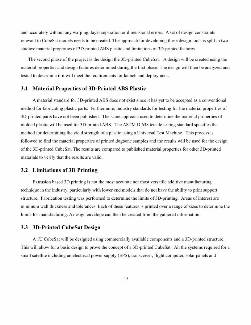
and accurately without any warping, layer separation or dimensional errors. A set of design constraints
relevant to CubeSat models needs to be created. The approach for developing these design tools is split in two
studies: material properties of 3D-printed ABS plastic and limitations of 3D-printed features.
The second phase of the project is the design the 3D-printed CubeSat. A design will be created using the
material properties and design features determined during the first phase. The design will then be analyzed and
tested to determine if it will meet the requirements for launch and deployment.
3.1 Material Properties of 3D-Printed ABS Plastic
A material standard for 3D-printed ABS does not exist since it has yet to be accepted as a conventional
method for fabricating plastic parts. Furthermore, industry standards for testing for the material properties of
3D-printed parts have not been published. The same approach used to determine the material properties of
molded plastic will be used for 3D-printed ABS. The ASTM D 638 tensile testing standard specifies the
method for determining the yield strength of a plastic using a Universal Test Machine. This process is
followed to find the material properties of printed dogbone samples and the results will be used for the design
of the 3D-printed CubeSat. The results are compared to published material properties for other 3D-printed
materials to verify that the results are valid.
3.2 Limitations of 3D Printing
Extrusion based 3D printing is not the most accurate nor most versatile additive manufacturing
technique in the industry, particularly with lower end models that do not have the ability to print support
structure. Fabrication testing was performed to determine the limits of 3D-printing. Areas of interest are
minimum wall thickness and tolerances. Each of these features is printed over a range of sizes to determine the
limits for manufacturing. A design envelope can then be created from the gathered information.
3.3 3D-Printed CubeSat Design
A 1U CubeSat will be designed using commercially available components and a 3D-printed structure.
This will allow for a basic design to prove the concept of a 3D-printed CubeSat. All the systems required for a
small satellite including an electrical power supply (EPS), transceiver, flight computer, solar panels and
15
antenna will be included in the design. The system will be modeled in Autodesk Inventor to determine
geometry and layout.
3.4 Analyses and Tests
The CubeSat design is validated through analyses and testing but actual flight tests will not be performed.
The material properties gathered during material testing will be used in a Finite Element Analysis of the
structure. Using Autodesk Inventor Simulation (Algor) FEA software the 3D-printed CubeSat system will be
analyzed under the Common Launch Vehicle load conditions to prove a positive margin of safety. Other
requirements from the CubeSat Design Specification including P-pod interface and dimensional accuracy [8]
will be validated. The analysis and test results will determine whether the design and 3D printing approach
can meet the basic requirements for a CubeSat.
4.0 Material Testing
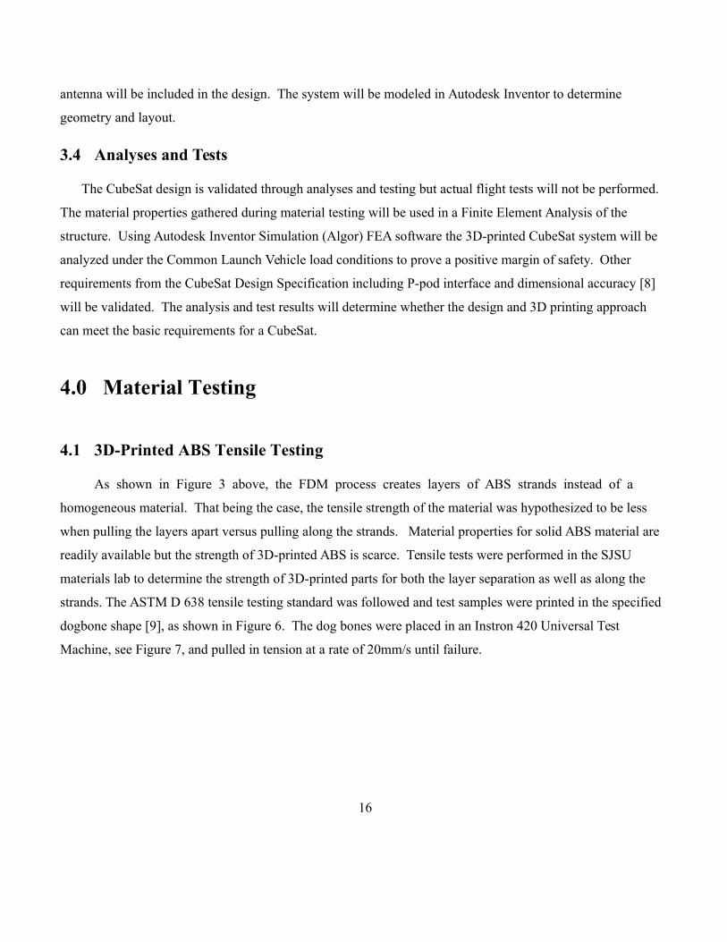
4.1 3D-Printed ABS Tensile Testing
As shown in Figure 3 above, the FDM process creates layers of ABS strands instead of a
homogeneous material. That being the case, the tensile strength of the material was hypothesized to be less
when pulling the layers apart versus pulling along the strands. Material properties for solid ABS material are
readily available but the strength of 3D-printed ABS is scarce. Tensile tests were performed in the SJSU
materials lab to determine the strength of 3D-printed parts for both the layer separation as well as along the
strands. The ASTM D 638 tensile testing standard was followed and test samples were printed in the specified
dogbone shape [9], as shown in Figure 6. The dog bones were placed in an Instron 420 Universal Test
Machine, see Figure 7, and pulled in tension at a rate of 20mm/s until failure.
16

Figure 6: ASTM D 638 Dogbone Test Coupon [9]
Figure 7: Instron Universal Test Machine, SJSU Materials Lab
Six dogbones were printed on a Stratasys Elite FDM printer in each the horizontal and vertical
orientation to test the effects of the layer separation. Additionally, two sample were printed on consumer
grade printers, UP! And BFB-3000. Figure 8 and Table 1 show the results of the tensile tests, with the stock
17

ABS being the rating on the raw feedstock material prior to printing. Both the horizontal and vertical tests
show the average of the samples tested.
Figure 8: Ultimate Tensile Strength of 3D-Printed Parts
The ultimate tensile strength for solid injection molded ABS is rated at 33 MPa. Testing showed the
strength of the adhesive bond (vertical tests) was significantly less than in the direction inline with the print
bead (horizontal tests). The horizontal print was about 79% of the strength of the original ABS while the
vertical dogbone was only 35% of the strength.
18

Table 1: Tensile Test Results
A test report from the prototyping company Protomold shows the results of tensile and flexural
testing of ABS material molded and FDM printed. The specifics of the material tested, the printer used to
make the FDM samples, and the testing parameters were not provided. However, their results were similar
but with over a 50% reduction in strength for the horizontal test and the vertical was still about 35% of the
baseline ABS.
19

Figure 9: Protomold Material Testing Molded vs FDM (Stork Labs, 2007)
The two tests both show similar results for the adhesive strength of the layers to be about 35% of the
regular ABS. This value will be used for the structural design of 3D-Printed CubeSat to insure that the
material strength is never exceeded.
5.0 Initial Fabrication Tests
A major hurdle for FDM printers is manufacturing quality parts and meeting tolerance standards. To get
an idea of the scope of challenges that will be faced while 3D printing a CubeSat structure, some initial
prototypes were printed.
Several FDM printers were used in this test process: the Cube by 3D Systems, UP! Plus by PP3DP, BFB-
3000 by 3D Systems, and the Dimensions Elite by Stratasys. While each system uses the FDM method for
creating 3D parts each utilizes custom software with different algorithms for creating the material path. This
resulted in different results and issues for each printer.
The baseline for CubeSat structures is a thin aluminum wall with corner posts. The initial prints were
based on a standard aluminum CubeSat structure design. The wall thickness printed was 1mm thick and was so
thin that the layers would not always stay adhered, see Figure 10. Also noticed during printing was the
dimensional accuracy of printers. While the Up! And BFB were within 20% of the 1mm thickness the Cube
printer was a full 2mm thick.
20

Figure 10: Wall CubeSat. Left: UP! Plus, Middle: BFB-300, Right: Cube
The 3D model was then modified to reduce splitting by creating a wall thickness of 2mm up from
1mm. The splitting was significantly reduced but still present. A new issue arose in that the bottom of the
CubeSats would warp and curl up during printing. This issue stems from the upper layers cooling faster than
the lower layers. When the upper layers cool they contract which creates tension on the bottom layers pulling
it off the print platform. Techniques such as better adhesion to the print surface and less dense walls will be
used to minimize this warping issue.
Figure 11: Warping
A structurally sound, uniform, non-warping CubeSat structure was printed when the wall thickness
was adjusted up to 4mm thick. To additionally reduce weight and warping the fill was set to sparse, which
creates a honeycomb-like structure between the wall faces, as seen in Figure 12. A successful 3D-printed
CubeSat structure shape has been created. This will be the starting point for future work designing the 3D-
printed CubeSat.
21

Figure 12: Left: 4mm Thick Sparse Wall Fill, Middle and Right: 4mm Thick Solid Wall
6.0 CubeSat Requirements
The CubeSat Design Specification Rev.12 [6] provides the general interface, launch and safety
requirements for CubeSats. CubeSats are commonly deployed by a Poly Picosatellite Orbital Deployer (P-
POD) which drives the dimensional, material and geometry requirements. Certain driving requirements that
are pertinent to the 3D-printed CubeSat design are outlined below:
Non-Hazardous Low Outgassing Material Total Mass Lost (TML) ≤ 1.0% Collected Volatile Condensable Material (CVCM) ≤ 0.1%
Dimensions (per Figure 24 in Appendix A) 100±0.1mm Wide, 113.5±0.1mm Tall Rails shall have a minimum width of 8.5mm Rails shall not have a surface roughness greater than 1.6µm
Mass and Material Not to exceed 1.33 kg mass CG shall be located within a 2cm sphere from the geometric center The rails and structure shall be Aluminum 7075 or 6061 or a Deviation Waiver Approval Request
(DAR) waiver must be completed.Launch Loads
To be provided by Launch Provider.
7.0 3D-Printed CubeSat Design
22

The preliminary 3D-printed CubeSat design contains standard low cost off the shelf CubeSat components.
The electrical power system (EPS), flight module, transceiver, and solar panels are catalog components from
Pumpkin, Inc. and Clyde Space. The structure is custom designed to be manufactured using an FDM printer.
Figure 13: 3D-Printed CubeSat Design
The Pumpkin FM430 Flight Module is a single board computer for harsh environments. The module
controls Command and Data Handling (C&DH), Communications (COM), mass storage and power switching.
The board requires a 5V power input to power its 16-bit microcontroller, temperature sensors, clocks and 3.3V
I/O. The module contains a 104-pin connector for stacking boards. A model of the FM430 is shown in Figure
14.
Figure 14: Pumpkin FM430 Flight Module
The Linear EPS Module from Pumpkin is a rechargeable electrical power system for CubeSat kits. It
provides a regulated 5V and 3.3V power supply using two 1500mAh Li-Poly batteries for a total of 11Wh of
power. The stackable design, shown in Figure 15, eliminates the need for additional wiring between boards.
The module also interfaces with the Solar Array to recharge the batteries.
23

Figure 15: Pumpkin Linear EPS Module
Communication is provided by a Microhard MHX transceiver for long range data transfer. The
transceiver is regularly used in consumer electronics so has been ruggedized to survive vibrations, impacts and
environmental hazards. Pumpkin, Inc. utilizes these transceivers for low cost CubeSat components. The
board components are contained in aluminum housing as shown in Figure 16.
Figure 16: Microhard MHX-series Transceivers
The six outer sides of the CubeSat will contain solar arrays for recharging the Li-poly batteries on the
EPS. A standard 1U Side Solar Panel from Clyde Space will be used for this design. The high efficiency solar
panels are composed of carbon fiber composites, aluminum and PCB substrates. They undergo qualification
testing including thermal cycling, vibration and shock testing before being shipped. The robust solar panels
will be suited for withstanding the ductility of an ABS plastic structure.
24

Figure 17: Clyde Space 1U CubeSat Side Solar Panel
The preliminary design for the CubeSat structure is based on the initial fabrication tests. A 4mm thick
wall with an optimized cross side panels, shown in Figure 18, is proven to be printable to required tolerances
with no warping or layer splitting. The outer dimensions including rails are designed into the structure to meet
the CubeSat specification drawing, as seen in Figure 24.
Figure 18: Preliminary 3D-Printed Structure Design
A complete 3D-printed CubeSat will include one EPS, one Flight Module, one transceiver, and six
solar panels as shown in Figure 19 below. Slot grooves were designed into the structure to accept the PCB
cards and a door was added to close out the opening. The off-the-shelf components only utilize one half of the
internal volume allowing the remaining half to be used for payloads or additional batteries.
25

Figure 19: 3D-Printed CubeSat CAD Design
8.0 3D-Printed CubeSat Fabrication
26

Upon completion of the 3D-printed CubeSat design the satellite was able to be immediately printed.
Additionally, each of the off the shelf components including the EPS, Flight Module, Modem and 4 solar
panels were printed to use as models for fit checks and orientation. The professional-grade Stratasys Elite
FDM printer was used to fabricate the model. The preliminary test prints showed that the lower end printers
would not be able to achieve the tolerances required for a CubeSat. By sticking to a 4mm minimum wall
thinkness the print did not show any signs of warping or layer splitting.
Figure 20: Printed CubeSat
The total print time for the structure elements was ~25 hours. At the standard 3D printing rate of $1.95
cm^3 for professionally printed ABS parts the total equivalent cost would be $294.451. The cost for a
comparable 1U CubeSat structure made from Aluminum but with no customization can be purchased for $925.
A custom CubeSat structure manufactured from a solid block of aluminum has a price of $10,500.
9.0 Analysis and Results
1 All cost estimations are as of April 2013. Aluminum structure pricing is from Cubesatkit.com.
27

Each of the driving requirements for the 3D-printed CubeSat were analyzed or verified to see if they can
be met by an extruded ABS structure. Nonconformance to any of the requirements does not imply that the 3D-
printed CubeSat cannot be flown. The CubeSat Design Specification includes a waiver process for satellites in
violation of any of the requirements.
9.1.1 Low Outgassing Material
Material outgassing is a major concern for most plastics used on satellites. The CubeSat Design Specification
specifies the outgassing requirements to be: Total Mass Lost (TML) ≤ 1.0%, and Collected Volatile
Condensable Material (CVCM) ≤ 0.1%. NASA maintains a database of material outgassing properties. While
the database does not contain all materials, a molded ABS casing is available as shown in Table 2. The ABS
casing has a TML value of 1.13 and a CVCM of 0.16 both of which are over the allowable amounts.
----------------------------------------------------------------------------------------------
MATERIAL % % CURE CURE AT- % DATA APPLICATION MFR
TML CVCM TIME TEMP MOS WVR REF CODE
----------------------------------------------------------------------------------------------
ABS VACUUM MOLDED CASING 1.13 0.16 6M 204 E-2 0.41 GSC11483 MOLD CPND SHE
LEXAN 500 POLYCARBONATE 0.10 0.00 GSFC4017 MOLD CPND GEC
ULTEM 9085 0.40 0.00 0.32 GSC32863 MOLDING COMPOUND SBC
POLYETHYLENE UHMW 0.02 0.00 GSFC4546 STRUCTURAL PHI
Table 2: Outgassing of Polymers ( http://outgassing.nasa.gov )
Since 3D-printed ABS is not listed in the database, the actual values are not available. It could be
argued that the material may ‘bake out’ during the extrusion process lowering the mass loss value. Further
testing on 3D printed ABS would need to be performed to verify that hypothesis or a design deviation waiver
for the CubeSat would need to be submitted.
If ABS proves to be unsuitable all hope is not lost for extrusion based 3D-printed CubeSats. Table 2
includes other less common printing materials that are well below the outgassing limits. These include
Polycarbonate and Ultem both of which are used by the Stratasys company.
28

9.1.2 Dimensions
The CubeSat Acceptance Checklist (CAC), as shown in Appendix B, has a set of dimensional and
design requirements that must be met by each satellite unless a deviation waiver is submitted. The width of
the 1U CubeSat must be within 100±0.1mm and the height 113.5±0.1mm. An inspection of the 3D-printed
CubeSat showed the width to be 99.9mm and the height 113.8mm. While the height of the rail is out of
tolerance, that could be remedied by reducing the dimensions in the CAD or by simply cutting off 0.3mm from
the top of each rail. The surface finish of ABS is not applicable as plastic has a much lower coefficient of friction and
would slide more easily than aluminum.
9.1.3 Launch Loads
The launch loads are taken from the general launch vehicle loads as defined by NASA per SSP 50835.
This encompassed the worse cases from all the vehicles that supply the ISS. Four cases were analyzed using
FEA with the g-loading as specified in Table 3 all with 12.5 g of load but in different orientations.
Liftoff and Landing X[g] Y[g] Z[g]
Case 1 + 12.5 + 12.5 + 12.5
Case 2 + 12.5 + 12.5 - 12.5
Case 3 - 12.5 + 12.5 + 12.5
Case 4 - 12.5 + 12.5 - 12.5
Table 3: General Launch Vehicle Loads [10]
Autodesk Inventor Simulations software was used to perform a finite elemement analysis. To simplify
the mesh and to analyze the worse case senario of a full 1kg payload, the circuit boards were removed from
the model and replaced with a dummy payload, Figure 21. The simulated payload was designed to fit in the
29

EPS card slot and the model material was set as steel. The structure and door were given custom material
properties using the material testing data and a tensile strength of 11.6MPa.
Figure 21: 1 kg Simulated Payload
A polygonal mesh was created of the CubeSat structure and the simulated payload, see Figure 22. The
mesh included 39239 nodes and 20176 elements. The model was fixed on the bottom face of each of the rails
and all components were bonded together.
30
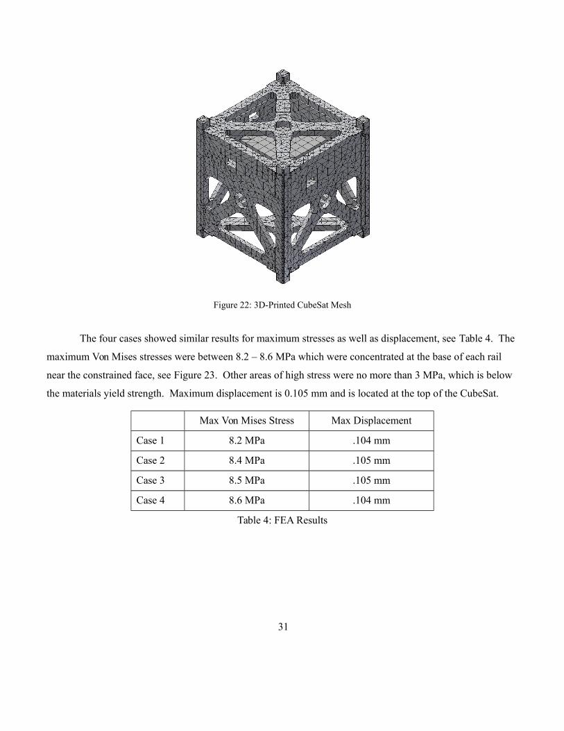
Figure 22: 3D-Printed CubeSat Mesh
The four cases showed similar results for maximum stresses as well as displacement, see Table 4. The
maximum Von Mises stresses were between 8.2 – 8.6 MPa which were concentrated at the base of each rail
near the constrained face, see Figure 23. Other areas of high stress were no more than 3 MPa, which is below
the materials yield strength. Maximum displacement is 0.105 mm and is located at the top of the CubeSat.
Max Von Mises Stress Max Displacement
Case 1 8.2 MPa .104 mm
Case 2 8.4 MPa .105 mm
Case 3 8.5 MPa .105 mm
Case 4 8.6 MPa .104 mm
Table 4: FEA Results
31

Figure 23: Von Mises Stresses, Top Row - Case1, 2, Bottom Row - Case 3, 4
32

10.0 Conclusion
The research and sample models printed point towards the feasibility of a functional 3D-printed CubeSat.
While the wall thickness would be thicker than a similar aluminum structure, the ability to customize at low
manufacturing cost can offset that design constraint. ABS is a very common, low end material for 3D
extrusion printing but may have limited usefulness in satellites. High outgassing could affect other launch
payloads as well as any optics on the CubeSat. A coating or another material may be required if either of these
are a concern.
33

Appendix A
Figure 24: CubeSat Specification Drawing
34

Appendix B
Figure 25: CubeSat Acceptance Checklist
35
References:
[1] H. Heidt, J. Puig-Suari, A. S. Moore, S. Nakasuka, R. J. Twiggs, “CubeSat: A new Generation of
Picosatellite for Education and Industry Low-Cost Space Experimentation,” AIAA/USU Conference on
Small Satellites, Aug. 21-24, 2000.
[2] Toorian, Armen et. al, "CubeSats as Responsive Satellites," Paper no. AIAA-RS3 2005-3001, AIAA
3rd Responsive Space Conference, Los Angeles, CA, 25-28 April 2005.
[3] Y. Kwon, L. Brewer, R. Panholzer, D. Sakoda, C. Park, “Direct Manufacturing of CubeSat
Using 3-D Digital Printer and Determination of Its Mechanical Properties” Naval Postgraduate School,
Monterey, CA.
[4] Davis, S., "Construction of a CubeSat Using Additive Manufacturing," SAE Technical
Paper 2011-01-2568, 2011.
[5] White, J., Holemans, W., Huang, A., "Make Your Cubesat Overnight and Put it in Any
Orbit(Well… almost)", Colorado Satellite Services, LLC, 2011.
[6] “CubeSat Design Specifications,” Rev.12, The CubeSat Program, Cal Poly San Luis
Obispo, CA.
[7] J. Hiemenz, “3D PRINTING WITH FDM: How it Works” white paper, Stratasys, Inc. [8] D. T.
Pham, S. S. Dimov, “Rapid manufacturing”, Springer-Verlag, 2001.
[8] Stanford University and California Polytechnic Institute at San Louis Obispo, “CubeSat Design
Specifications Document”, Revision 12, August 2009.
[9] ASTM D 638: Standard Test Method for Tensile Strength of Plastics, Annual Book of ASTM
Standards, ASTM International, West Conshohocken, PA, 2010.
[10] SSP 50835, “ISS Pressurized Volume Hardware Common Interface Requirement Document,
International Space Station”, NASA, Revision C, November 2011.
36