Embed Size (px)
Citation preview
International Research Journal of Engineering and Technology (IRJET) e-ISSN: 2395-0056
Volume: 08 Issue: 05 | May 2021 www.irjet.net p-ISSN: 2395-0072
© 2021, IRJET | Impact Factor value: 7.529 | ISO 9001:2008 Certified Journal | Page 1322
Overview of Additive Manufacturing Technologies
Rohit Prakash Pawar1, Rushikesh Suresh Nikumbh2, Shruti Kiran Mali3
1Student, Production Engineering, Sinhgad College of Engineering, Pune, Maharashtra, India 2Student, Mechanical Engineering, MVPS’s KBT College of Engineering, Nashik, Maharashtra, India
3Student of M. Tech, Institute of Chemical Technology Mumbai, Marathwada Jalna Campus, Maharashtra, India ---------------------------------------------------------------------***----------------------------------------------------------------------Abstract - In architecture, processing, and delivery to end-
users, additive manufacturing (AM) or three-dimensional (3D)
printing has implemented a novel development process. It's a
cyclic manufacturing technique that uses a 3D CAD model to
create three-dimensional structures layer by layer. This
technology has given designers a lot of leeway when it comes
to designing sophisticated materials, easily customized goods,
and even e-commerce websites. This technology has given
designers a lot of leeway when it comes to designing dynamic
materials, easily customized objects, and waste minimization.
Industry 4.0, the most recent technological development,
combines smart production processes with advanced
information technology. The methods are relatively
unrestrictive in terms of material form. The challenge for a
designer is to use additive manufacturing's special features in
the production process to bring value to a product for both the
manufacturer and the end customer. This paper include
discussion of additive manufacturing processes and their
implementation, as well as an analysis of how this
manufacturing process used Along with materials.
Key Words: Smart Manufacturing, Industry 4.0, Additive Manufacturing, 3D Printing,
1. INTRODUCTION Innovative and cutting-edge scientific practices associated
with industrial techniques, products, and product production
is critical to the evolution of industries. Due to its potential
to produce dynamic geometries with customized material
properties, additive manufacturing, or three-dimensional (3-
D) printing, is gaining unparalleled interest in today's age.
There are several additive manufacturing options.
Prototypes and fully working artifacts may be created using
a variety of additive manufacturing (AM) technologies.
Despite their differences in solution, concept, and
embodiment, the technologies share a lot of practical
similarities. Additive manufacturing is a group of new
developments that use additive manufacturing to create
three-dimensional structures directly from computer
models. Additive manufacturing is a group of advanced
technologies that use an additive method to create three-
dimensional structures directly from computer models,
usually by depositing and curing successive layers of
polymers, ceramics, or metals. 2 Unlike typical
manufacturing processes that include subtraction (such as
cutting and shearing) and shaping (such as stamping,
bending, and so on), Materials are joined together to create
products in additive manufacturing.
1.1 DEFINITION[1] AM has evolved since the early days of rapid prototyping,
and as a diverse area of research, it has amassed a wealth of
vocabulary. The ASTM F-42 committee was recently
established to develop industry standards and standardize
AM terminology.
“The process of joining materials to make objects from 3D
model data, usually layer upon layer, as opposed to
subtractive manufacturing technologies.”
A key point in this definition is that in order to qualify as AM
under the ASTM definition, the 3D model data controlled by
a computer must be used as a design precursor. Simply
adding or building up material is not included in this
process definition The concept of automation and control
using software is critical in determining what falls under AM
technology and what does not. AM is referred to by several
different terms, including additive fabrication, additive layer
manufacturing, direct digital manufacturing, and freeform
fabrication.
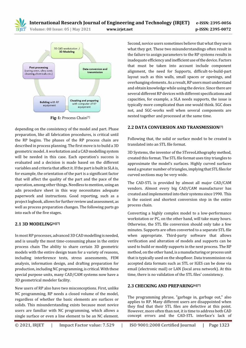
2. PROCESS CHAIN[7]
All RP strategies use the same basic methodology, as defined
in Section 1. As a result, all RP structures have a process chain
that is identical. Figure 1 depicts a simplified phase chain.
The chain has a total of five stages, all of which are 3D
modelling, data conversion and storage, building inspection
and preparation, and postprocessing. The method can be
iterated before a suitable model or component is obtained,
International Research Journal of Engineering and Technology (IRJET) e-ISSN: 2395-0056
Volume: 08 Issue: 05 | May 2021 www.irjet.net p-ISSN: 2395-0072
© 2021, IRJET | Impact Factor value: 7.529 | ISO 9001:2008 Certified Journal | Page 1323
Fig-1: Process Chain[7]
depending on the consistency of the model and part. Phase
preparation, like all fabrication procedures, is critical until
the RP begins. The phases of the RP process chain are
described in process planning. The first move is to build a 3D
geometric model. A workstation and a CAD modelling system
will be needed in this case. Each operation's success is
evaluated and a decision is made based on the different
variables and criteria that affect it. If the part is built in SLA is,
for example, the orientation of the part is a significant factor
that will affect the quality of the part and the pace of the
operation, among other things. Needless to mention, using an
adn procedure sheet in this way necessitates adequate
paperwork and instructions. Good reporting, such as a
project logbook, allows for further review and assessment, as
well as process preparation changes. The following parts go
into each of the five stages.
2.1 3D MODELING[6][7]
In most RP processes, advanced 3D CAD modelling is needed,
and is usually the most time-consuming phase in the entire
process chain The ability to share certain 3D geometric
models with the entire design team for a variety of reasons,
including interference tests, stress assessments, FEM
analysis, information design, and drafting preparation for
production, including NC programming, is critical. With these
special purpose units, many CAD/CAM systems now have a
3D geometrical modeler facility.
New users of RP also have two misconceptions. First, unlike
NC programming, RP needs a closed volume of the model,
regardless of whether the basic elements are surfaces or
solids. This misunderstanding exists because most novice
users are familiar with NC programming, which allows a
single surface or even a line element to be an NC element.
Second, novice users sometimes believe that what they see is
what they get. These two misunderstandings often result in
the failure to assign parameters to the RP systems results in
inadequate efficiency and inefficient use of the device. Factors
that must be taken into account include component
alignment, the need for Supports, difficult-to-build-part
layout such as thin walls, small spaces or openings, and
overhanging elements. As a result, RP users must understand
and obtain knowledge while using the device. Since there are
several different RP devices with different specifications and
capacities, for example, a SLA needs supports, the issue is
typically more complicated than one would think. SGC does
not, and SGC-works well when several components are
nested together and processed at the same time.
2.2 DATA CONVERSION AND TRANSMISSION[7]
Following that, the solid or surface model to be created is
translated into an STL file format.
3D Systems, the inventor of the STereoLithography method,
created this format. The STL file format uses tiny triangles to
approximate the model's surfaces. Highly curved surfaces
need a greater number of triangles, implying that STL files for
curved sections may be very wide.
The CAD-STL is provided by almost all major CAD/CAM
vendors. Almost every big CAD/CAM manufacturer has
created and implemented into their systems since 1990. This
is the easiest and shortest conversion step in the entire
process chain.
Converting a highly complex model to a low-performance
workstation or PC, on the other hand, will take many hours.
Otherwise, the STL file conversion should only take a few
minutes. Supports are often converted to a separate STL file
when appropriate. Third-party software that allows
verification and alteration of models and supports can be
used to build or modify supports in the next process. The RP
method, on the other hand, is a manufacturing or process unit
that is typically used on the shopfloor. Data transmission via
accepted data formats such as STL or IGES can be done via
email (electronic mail) or LAN (local area network). At this
time, there is no validation of the STL files' consistency.
2.3 CHECKING AND PREPARING[6][7]
The programming phrase, "garbage in, garbage out," also applies to RP. Many different users are disappointed when they find that their STL files are defective at this point. However, more often than not, it is time to address both CAD concept errors and the CAD-STL interface's lack of
International Research Journal of Engineering and Technology (IRJET) e-ISSN: 2395-0056
Volume: 08 Issue: 05 | May 2021 www.irjet.net p-ISSN: 2395-0072
© 2021, IRJET | Impact Factor value: 7.529 | ISO 9001:2008 Certified Journal | Page 1324
robustness. Unfortunately, today's CAD models, whose quality is reliant on the CAD system's human operators and post processes, continue to suffer from a broad range of issues, including the production of undesirable shell-punctures (i.e. holes gaps cracks, etc.) If these issues are not addressed, systems downstream may often crash. uilding criteria for positioning and stepwise manufacturing can be difficult to prepare in terms of the many possible options. not followed by enough paperwork These options involve determining geometrical objects and building orientation. spanal assortments, assembly with other pieces, necessary support systems, and slice parameters. In the case of SLA, they also require the determination of technical parameters such as cure depth, laser strength, and other physical parameters. It means that user-friendly tools for use and treating, user assistance in terms of user Mangals, conversation mode, and online multimedia aids would be extremely beneficial.
2.4 BUILDING[7]
This move is completely automated in most RP systems. As a result, it is common for operators to keep the system running overnight to build parts. Depending on the size and amount of parts involved, the construction process could take many hours. The number of similar parts that can be designed is limited by the total build scale, which is restricted by the RP-build system's volume.
2.5 POST PROCESSING[7]
The post processing task is the final step in the process chain. Any manual operations are usually required at this level. As a consequence, the risk of losing a component is especially high. As a result, the operator for this final phase stage bears a great deal of responsibility for the effective completion of the process.
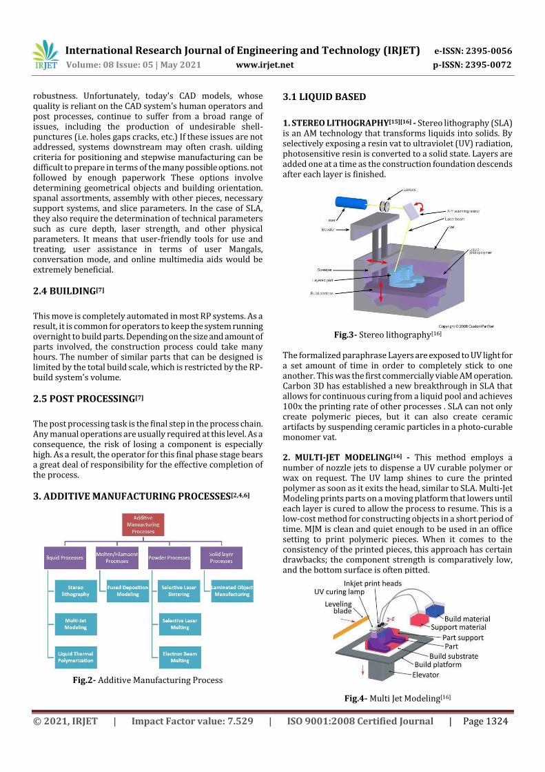
3. ADDITIVE MANUFACTURING PROCESSES[2,4,6]
Fig.2- Additive Manufacturing Process
3.1 LIQUID BASED
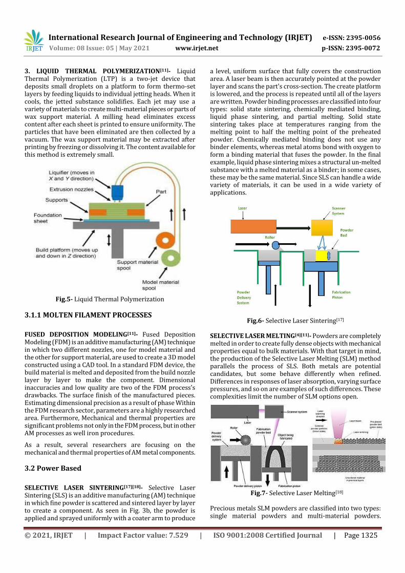
1. STEREO LITHOGRAPHY[15][16] - Stereo lithography (SLA) is an AM technology that transforms liquids into solids. By selectively exposing a resin vat to ultraviolet (UV) radiation, photosensitive resin is converted to a solid state. Layers are added one at a time as the construction foundation descends after each layer is finished.
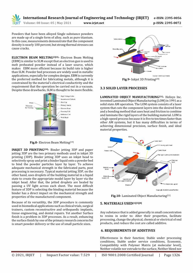
Fig.3- Stereo lithography[16] The formalized paraphrase Layers are exposed to UV light for a set amount of time in order to completely stick to one another. This was the first commercially viable AM operation. Carbon 3D has established a new breakthrough in SLA that allows for continuous curing from a liquid pool and achieves 100x the printing rate of other processes . SLA can not only create polymeric pieces, but it can also create ceramic artifacts by suspending ceramic particles in a photo-curable monomer vat. 2. MULTI-JET MODELING[16] - This method employs a number of nozzle jets to dispense a UV curable polymer or wax on request. The UV lamp shines to cure the printed polymer as soon as it exits the head, similar to SLA. Multi-Jet Modeling prints parts on a moving platform that lowers until each layer is cured to allow the process to resume. This is a low-cost method for constructing objects in a short period of time. MJM is clean and quiet enough to be used in an office setting to print polymeric pieces. When it comes to the consistency of the printed pieces, this approach has certain drawbacks; the component strength is comparatively low, and the bottom surface is often pitted.
Fig.4- Multi Jet Modeling[16]
International Research Journal of Engineering and Technology (IRJET) e-ISSN: 2395-0056
Volume: 08 Issue: 05 | May 2021 www.irjet.net p-ISSN: 2395-0072
© 2021, IRJET | Impact Factor value: 7.529 | ISO 9001:2008 Certified Journal | Page 1325
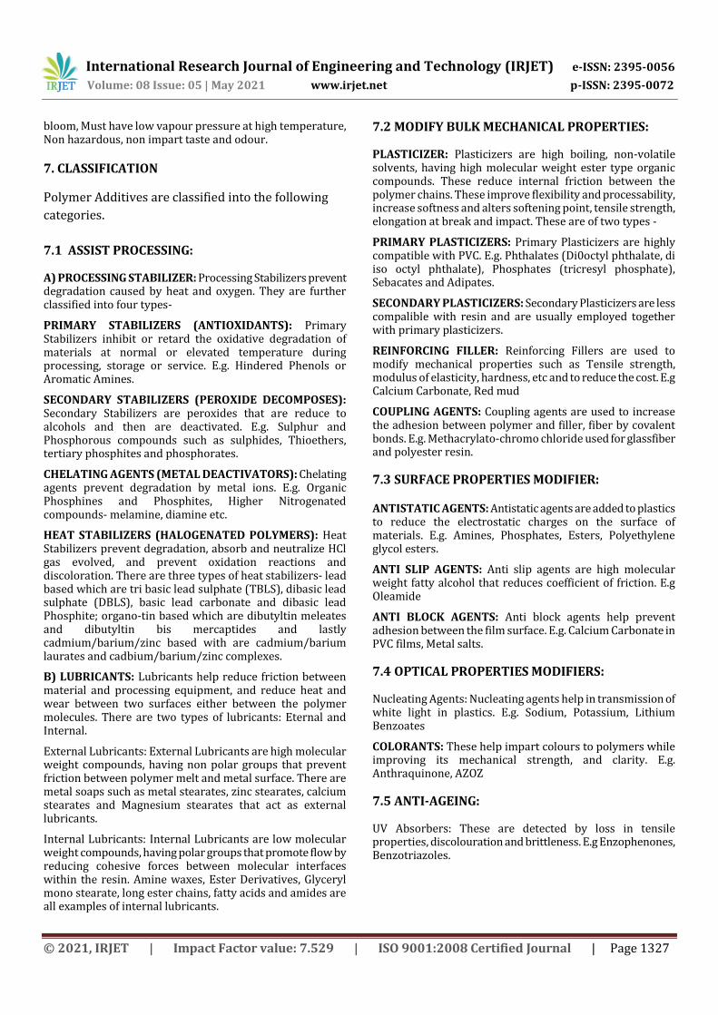
3. LIQUID THERMAL POLYMERIZATION[11]- Liquid Thermal Polymerization (LTP) is a two-jet device that deposits small droplets on a platform to form thermo-set layers by feeding liquids to individual jetting heads. When it cools, the jetted substance solidifies. Each jet may use a variety of materials to create multi-material pieces or parts of wax support material. A milling head eliminates excess content after each sheet is printed to ensure uniformity. The particles that have been eliminated are then collected by a vacuum. The wax support material may be extracted after printing by freezing or dissolving it. The content available for this method is extremely small.
Fig.5- Liquid Thermal Polymerization
3.1.1 MOLTEN FILAMENT PROCESSES
FUSED DEPOSITION MODELING[11]- Fused Deposition Modeling (FDM) is an additive manufacturing (AM) technique in which two different nozzles, one for model material and the other for support material, are used to create a 3D model constructed using a CAD tool. In a standard FDM device, the build material is melted and deposited from the build nozzle layer by layer to make the component. Dimensional inaccuracies and low quality are two of the FDM process's drawbacks. The surface finish of the manufactured pieces. Estimating dimensional precision as a result of phase Within the FDM research sector, parameters are a highly researched area. Furthermore, Mechanical and thermal properties are significant problems not only in the FDM process, but in other AM processes as well iron procedures.
As a result, several researchers are focusing on the mechanical and thermal properties of AM metal components.
3.2 Power Based
SELECTIVE LASER SINTERING[17][18]- Selective Laser Sintering (SLS) is an additive manufacturing (AM) technique in which fine powder is scattered and sintered layer by layer to create a component. As seen in Fig. 3b, the powder is applied and sprayed uniformly with a coater arm to produce
a level, uniform surface that fully covers the construction area. A laser beam is then accurately pointed at the powder layer and scans the part's cross-section. The create platform is lowered, and the process is repeated until all of the layers are written. Powder binding processes are classified into four types: solid state sintering, chemically mediated binding, liquid phase sintering, and partial melting. Solid state sintering takes place at temperatures ranging from the melting point to half the melting point of the preheated powder. Chemically mediated binding does not use any binder elements, whereas metal atoms bond with oxygen to form a binding material that fuses the powder. In the final example, liquid phase sintering mixes a structural un-melted substance with a melted material as a binder; in some cases, these may be the same material. Since SLS can handle a wide variety of materials, it can be used in a wide variety of applications.
Fig.6- Selective Laser Sintering[17] SELECTIVE LASER MELTING[4][11]- Powders are completely melted in order to create fully dense objects with mechanical properties equal to bulk materials. With that target in mind, the production of the Selective Laser Melting (SLM) method parallels the process of SLS. Both metals are potential candidates, but some behave differently when refined. Differences in responses of laser absorption, varying surface pressures, and so on are examples of such differences. These complexities limit the number of SLM options open.
Fig.7- Selective Laser Melting[18]
Precious metals SLM powders are classified into two types: single material powders and multi-material powders.
International Research Journal of Engineering and Technology (IRJET) e-ISSN: 2395-0056
Volume: 08 Issue: 05 | May 2021 www.irjet.net p-ISSN: 2395-0072
© 2021, IRJET | Impact Factor value: 7.529 | ISO 9001:2008 Certified Journal | Page 1326
Powders that have been alloyed Single substance powders are made up of a single form of alloy, such as pure titanium. In this case, measurements demonstrate that the component density is nearly 100 percent, but strong thermal stresses can cause cracks.
ELECTRON BEAM MELTING[2][4]- Electron Beam Melting (EBM) is similar to SLM except that an electron gun is used to melt preheated powder instead of a laser source, which makes EBM more efficient because its build rate is higher than SLM. Powder bed processes are widely used in metallic applications, especially for complex designs. EBM is currently the preferred method for fabricating metals, although it is constrained by the material's electrical conductivity and the requirement that the operation be carried out in a vacuum. Despite these drawbacks, SLM is thought to be more flexible.
Fig.8- Electron Beam Melting[19] INKJET 3D PRINTING[20]- Binder jetting 3DP and paper jetting 3DP are the two primary methods used in inkjet 3D printing (3DP). Binder jetting 3DP uses an inkjet head to selectively spray and print a binder liquid onto a powder bed to bind the powder particles layer by layer. To achieve adequate mechanical strength in the fabricated parts, post processing is necessary. Typical material jetting 3DP, on the other hand, uses droplets of the building material in a liquid state to create the appropriate model layer by layer via the inkjet head. After that, the jetted droplets are healed by passing a UV light across each sheet. The most difficult feature of 3DP is selecting the binding material because the binder has a direct impact on the mechanical strength and properties of the manufactured component.
Because of its versatility, the 3DP procedure is commonly used in biomedical applications such as clinical trials, surgical trainers, custom reconstructive and orthopaedic implants, tissue engineering, and dental repairs. Yet another Surface finish is a problem in 3DP processes. As a result, enhancing the surface finish by one of the primary research concerns for is smart powder delivery or the use of small particle sizes.
Fig.9- Inkjet 3D Printing[20]
3.3 SOLID LAYER PROCESSES
LAMINATED OBJECT MANUFACTURING[21]- Helisys Inc. invented Laminated Object Manufacturing (LOM) in 1991 as a solid state AM operation. The LOM system consists of a laser system that cuts the component layers into the desired form and a bonding method that uses heat and friction to combine and laminate the rigid layers of the building material. LOM is a high-speed process because it is five to ten times faster than other AM systems, but it has many difficulties in terms of achieving dimensional precision, surface finish, and ideal material properties.
Fig.10- Laminated Object Manufacturing[21]
5. MATERIALS USED[1][5][8]
Any substance that is added generally in small concentration to resins in order to: Alter their properties, facilitate processing, change the physical, chemical or electrical of end products, and reduce the cost are called additive. 6. REQUIREMENTS OF ADDITIVES Effectiveness in their function; Stable under processing conditions, Stable under service conditions, Economic, Compatibility with Polymer Matrix (at molecular level), Neither volatile nor extrude to the surface, Neither bleed nor
International Research Journal of Engineering and Technology (IRJET) e-ISSN: 2395-0056
Volume: 08 Issue: 05 | May 2021 www.irjet.net p-ISSN: 2395-0072
© 2021, IRJET | Impact Factor value: 7.529 | ISO 9001:2008 Certified Journal | Page 1327
bloom, Must have low vapour pressure at high temperature, Non hazardous, non impart taste and odour. 7. CLASSIFICATION
Polymer Additives are classified into the following
categories.
7.1 ASSIST PROCESSING:
A) PROCESSING STABILIZER: Processing Stabilizers prevent degradation caused by heat and oxygen. They are further classified into four types-
PRIMARY STABILIZERS (ANTIOXIDANTS): Primary Stabilizers inhibit or retard the oxidative degradation of materials at normal or elevated temperature during processing, storage or service. E.g. Hindered Phenols or Aromatic Amines.
SECONDARY STABILIZERS (PEROXIDE DECOMPOSES): Secondary Stabilizers are peroxides that are reduce to alcohols and then are deactivated. E.g. Sulphur and Phosphorous compounds such as sulphides, Thioethers, tertiary phosphites and phosphorates.
CHELATING AGENTS (METAL DEACTIVATORS): Chelating agents prevent degradation by metal ions. E.g. Organic Phosphines and Phosphites, Higher Nitrogenated compounds- melamine, diamine etc.
HEAT STABILIZERS (HALOGENATED POLYMERS): Heat Stabilizers prevent degradation, absorb and neutralize HCl gas evolved, and prevent oxidation reactions and discoloration. There are three types of heat stabilizers- lead based which are tri basic lead sulphate (TBLS), dibasic lead sulphate (DBLS), basic lead carbonate and dibasic lead Phosphite; organo-tin based which are dibutyltin meleates and dibutyltin bis mercaptides and lastly cadmium/barium/zinc based with are cadmium/barium laurates and cadbium/barium/zinc complexes.
B) LUBRICANTS: Lubricants help reduce friction between material and processing equipment, and reduce heat and wear between two surfaces either between the polymer molecules. There are two types of lubricants: Eternal and Internal.
External Lubricants: External Lubricants are high molecular weight compounds, having non polar groups that prevent friction between polymer melt and metal surface. There are metal soaps such as metal stearates, zinc stearates, calcium stearates and Magnesium stearates that act as external lubricants.
Internal Lubricants: Internal Lubricants are low molecular weight compounds, having polar groups that promote flow by reducing cohesive forces between molecular interfaces within the resin. Amine waxes, Ester Derivatives, Glyceryl mono stearate, long ester chains, fatty acids and amides are all examples of internal lubricants.
7.2 MODIFY BULK MECHANICAL PROPERTIES:
PLASTICIZER: Plasticizers are high boiling, non-volatile solvents, having high molecular weight ester type organic compounds. These reduce internal friction between the polymer chains. These improve flexibility and processability, increase softness and alters softening point, tensile strength, elongation at break and impact. These are of two types -
PRIMARY PLASTICIZERS: Primary Plasticizers are highly compatible with PVC. E.g. Phthalates (Di0octyl phthalate, di iso octyl phthalate), Phosphates (tricresyl phosphate), Sebacates and Adipates.
SECONDARY PLASTICIZERS: Secondary Plasticizers are less compalible with resin and are usually employed together with primary plasticizers.
REINFORCING FILLER: Reinforcing Fillers are used to modify mechanical properties such as Tensile strength, modulus of elasticity, hardness, etc and to reduce the cost. E.g Calcium Carbonate, Red mud
COUPLING AGENTS: Coupling agents are used to increase the adhesion between polymer and filler, fiber by covalent bonds. E.g. Methacrylato-chromo chloride used for glassfiber and polyester resin. 7.3 SURFACE PROPERTIES MODIFIER:
ANTISTATIC AGENTS: Antistatic agents are added to plastics to reduce the electrostatic charges on the surface of materials. E.g. Amines, Phosphates, Esters, Polyethylene glycol esters.
ANTI SLIP AGENTS: Anti slip agents are high molecular weight fatty alcohol that reduces coefficient of friction. E.g Oleamide
ANTI BLOCK AGENTS: Anti block agents help prevent adhesion between the film surface. E.g. Calcium Carbonate in PVC films, Metal salts. 7.4 OPTICAL PROPERTIES MODIFIERS:
Nucleating Agents: Nucleating agents help in transmission of white light in plastics. E.g. Sodium, Potassium, Lithium Benzoates
COLORANTS: These help impart colours to polymers while improving its mechanical strength, and clarity. E.g. Anthraquinone, AZOZ 7.5 ANTI-AGEING:
UV Absorbers: These are detected by loss in tensile properties, discolouration and brittleness. E.g Enzophenones, Benzotriazoles.
International Research Journal of Engineering and Technology (IRJET) e-ISSN: 2395-0056
Volume: 08 Issue: 05 | May 2021 www.irjet.net p-ISSN: 2395-0072
© 2021, IRJET | Impact Factor value: 7.529 | ISO 9001:2008 Certified Journal | Page 1328
7.6 FUNGICIDES OTHERS:
BLOWING AGENTS: Also known as foaming agents, these upon heating liberate gases. These are used to produce porous polymers. There are two types of blowing agents
PHYSICAL BLOWING AGENTS: These are low cost agents which leave no solid residue after the reaction. E.g. Tricholorofluromethane is used to produce PU foam.
CHEMICAL BLOWING AGENTS: These decompose on heating to produce free radicals and nitrogen gas. E.g Azo Dicarbonamide
FLAME RETARDERS: The polymer based additives that prevent combustion by insulation, creating endothermic cooling reaction or by coating the product are called flame retarders. E.g. Zinc borate, Antimony trioxides, etc.
8. APPLICATIONS OF ADDITIVE
MANUFACTURING[5][3]
AUTOMOTIVE INDUSTRY- Metal additive manufacturing has major consequences for component production, as well as supply chains and inventory processes, which is especially important in the automotive industry. Fabricating complex lightweight components is a valuable aspect of utilizing metal AM processes in the automotive industry. The weight of vehicle components can be greatly minimized by using AM processes' ability to manufacture parts with complicated geometries while retaining relative strengths. AM-produced automotive parts include structural composite components, engine valves, and turbocharger turbines. A major benefit is in-house and on-demand manufacturing, which lowers inventory requirements, transportation costs, and material sourcing costs [63]. Regardless of the capability of AM processes in the automobile industry, the components manufactured must meet those performance requirements. The key challenges in the AM of automotive components are: thermal stresses caused in the AM parts, which influence the repeatability and efficiency of these parts, surface finish and dimensional accuracies, and part size. Furthermore, owing to normal output rates, processing speed is important.
TOOLING INDUSTRY - For the tooling industry, AM can save time by reducing fabrication phases and reduce costs by eliminating material loss associated with conventional subtractive manufacturing.
Furthermore, AM technology allows for the development of specialised moulds with tailored cooling channels, which can impart unique properties to parts while reducing manufacturing cycle time. AM moulds with integrated conformal cooling often have a longer service life so the manufacturer can reduce the thermal stress loading that the die faces . The mechanical behaviour of AM-fabricated tools influences their efficiency and service life. In general, consistency assessments for tools are strongly recommended. fabricated using additive manufacturing to completely evaluate their cost and efficiency value for an application.
NANOMANUFACTURING- AM technologies have recently been combined with nanotechnology to create parts out of new nanocomposites The primary advantage of using nanomaterials in AM processes is improving the material properties of the manufactured components Parts with improved visual, thermal, and mechanical properties It has been discovered that electrochemical and mechanical properties can be obtained. Carbon nanotubes, nanowires, metal nanoparticles, nano-graphene, and quantum dots have all been used in AM processes over the last few decades [71].
Nanoscale additive manufacturing (AM) is critical in processing metal parts with nanopores, thus reducing or mitigating the forming of pores and voids.
HEALTHCARE INDUSTRY- The use of metal additive manufacturing technologies in the healthcare industry is briefly discussed. AM procedures are used in the dental industry to create specific dental crowns, bridges, and implants. The SLM process's ability to create custom, complicated, precise, and completely dense objects makes it ideal for dental applications. Scanning the dental impression of the patient's teeth, digital modelling of the component, and then SLM creation are the steps in the process of making crowns and bridges. This process creates a dynamic demand for AM dental implants that competes with conventional casting and milling manufacturing methods. A parallel procedure is also used to create custom prostheses and supports for artificial teeth made of titanium or cobalt-chromium [68].
Furthermore, owing to their ability to easily manufacture highly customised parts, metal AM processes are used in the medical industry. There is no question that custom implant fabrication is more precise than previous conventional approaches.
The biggest benefit of additive manufacturing in the medical sector is its potential to manufacture highly complex components at low cost, as well as personalised components. CONCLUSION The early versions of additive manufacturing for producing quick prototypes that were initiated by the need of speeding up the process of model creation and shortening the time between product development and market positioning are discussed in this paper article. Additive manufacturing processes use data from a CAD file, which is then translated to an STL file. During this step, the CAD software drawing is approximated by triangles and cut, containing the details for each layer that will be printed. There is also a discussion of the related additive manufacturing processes and their implementations, as well as an analysis of how these additive manufacturing processes are used to make the components. Because of the constant and growing growth seen since the early days, as well as the promising outcomes achieved to date, there is hope that additive manufacturing will play an important role in the future of manufacturing.
The Society of Manufacturing Engineers classified different innovations in 2004 [1], but there are at least four additional
International Research Journal of Engineering and Technology (IRJET) e-ISSN: 2395-0056
Volume: 08 Issue: 05 | May 2021 www.irjet.net p-ISSN: 2395-0072
© 2021, IRJET | Impact Factor value: 7.529 | ISO 9001:2008 Certified Journal | Page 1329
notable technologies in 2012. Additive manufacturing innovations have been embraced in the aerospace industry because they allow for the production of lightweight materials, which is a shared aim of aircraft and spacecraft designers.
In the automobile industry, additive processing is useful for reproducing difficult-to-find components, such as those for vintage automobiles. Additive engineering is changing medical practise; it is now possible to provide an exact model of a bone before surgery and to have an effective graft, regardless of how complex its type is. However, since not all widely used packaging material can be treated, there is still a lot of study and testing to be done before additive manufacturing techniques become the norm in the manufacturing industry. To remove the need for a finishing process and to be able to manufacture parts requiring the highest degree of precision, the accuracy must be improved.
REFERENCES
RESEARCH PAPERS AND ARTICALS:
1. P. P. Kruth, “Material incress manufacturing by rapid prototyping techniques,” CIRP Annals—Manufacturing Technology, vol. 40, no. 2, pp. 603–614, 1991. View at: Publisher Site | Google Scholar
2. S. Ashley, “Rapid prototyping systems,” Mechanical Engineering, vol. 113, no. 4, p. 34, 1991. View at: Google Scholar
3. R. Noorani, Rapid Prototyping—Principles and Applications, John Wiley & Sons, 2006.
4. A Review of Additive Manufacturing, Kaufui V. Wong and Aldo Hernandez, Department of Mechanical and Aerospace Engineering, University of Miami, Coral Gables, FL 33146, USA
5. Mostafa Yakouta*, M. A. Elbestawib and Stephen C. Veldhuis A Review of Metal Additive Manufacturing Technologies Department of Mechanical Engineering, McMaster University , 1280 Main Street West, Hamilton, ON L8S 4L7, Canada.
6. Burns, M., Research Notes. Rapid Prototyping Report 4(3) (1994) 3-6.
7. Kochan. D. and Chau, C.K., “Solid freeform Manufacturing Assessment and Improvement at the entire process chain.” Prototyping for the Automotive Industries, ISATA94, Achan, Germany, 31 Oct to 4 Nov 94.
8. Materialization, N.V., Magics 3.01 Materialize User Manual. Materialize Software Department, Kaperldreef 60, B-3001 Heverlee, Belgium, 1944.
9. 3D System, SLA User Reference Manual.
WEBSITES
10. https://ewi.org/wp-content/uploads/2013/06/Additive-Manufacturing-DOT-Paper-2011.pdf
11. https://www.slideshare.net/taruian/module-1-additive-manufacturing
12. https://www.slideshare.net/StephinAbrahamSabu/additive-manufacturing-ppt
13. https://www.nist.gov/system/files/documents/2017/05/09/Murrish-Boeing-Intro-to-AM.pdf
14. https://home.iitk.ac.in/~nsinha/Additive_Manufacturing%20I.pdf
15. https://www.custompartnet.com/wu/stereolithography
16. https://www.researchgate.net/figure/arious-3D-printing-techniques-A-Stereolithography-SL-B-multi-jet-modeling-MJM_fig2_299655378
17. https://manufactur3dmag.com/how-selective-laser-sintering-works/
18. https://www.livescience.com/38862-selective-laser-sintering.html
19. https://www.whiteclouds.com/3DPedia/ebm.html
20. https://www.custompartnet.com/wu/ink-jet-printing
21. https://www.custompartnet.com/wu/laminated-object-manufacturing