Embed Size (px)
Citation preview

Challenges of additive manufacturing technologies froman optimisation perspective
Sofiane Guessasma1,*, Weihong Zhang2, Jihong Zhu2, Sofiane Belhabib3, and Hedi Nouri4
1 INRA, UR1268 Biopolymères Interactions Assemblages, 44300 Nantes, France2 Laboratory of Engineering Simulation & Aerospace Computing-ESAC, Northwestern Polytechnical University, 710072 Xian, Shaanxi,
P.R. China3 LUNAM University of Nantes Angers Le Mans, CNRS, GEPEA, UMR 6144, IUT de Nantes, 2 avenue du Professeur Jean Rouxel,
44475 Carquefou Cedex, France4 Department of Polymers and Composites Technology & Mechanical Engineering, Mines Douai, 941 rue Charles Bourseul, CS 10838,
59508 Douai, France
Received 29 October 2015 / Accepted 31 December 2015
Abstract – Three-dimensional printing offers varied possibilities of design that can be bridged to optimisation tools.In this review paper, a critical opinion on optimal design is delivered to show limits, benefits and ways of improve-ment in additive manufacturing. This review emphasises on design constrains related to additive manufacturing anddifferences that may appear between virtual and real design. These differences are explored based on 3D imagingtechniques that are intended to show defect related processing. Guidelines of safe use of the term ‘‘optimal design’’are derived based on 3D structural information.
Key words: Additive Manufacturing, Topological optimisation, Process-induced defects, X-ray micro-tomography.
1 Introduction
Additive Manufacturing (AM) is a collection of versatiletechniques of rapid prototyping that allow material design from3D digital models [1–3]. The term AM comes also under dif-ferent other nicknames such as direct digital manufacturing orsolid freeform fabrication [4, 5]. AM is rated as one of themost promising technology for design [6], presented as anew industrial revolution [7], and a vector for creativity [8],impact [9] and interrogations [10]. The laying down of thematerial in different states including liquid, powder and fusedmaterial defines roughly categories of AM [2, 7, 11–13]. Moreaccurate classifications do exist such as the ASTM F42reported in reference [14]. Wide varieties of materials can beprocessed using additive manufacturing including metals[15–18], alloys [19–22], ceramics [23–26], polymers [27–30],composites [31–34], airy structures [35, 36] and multi-phasematerials [37–39].
The main characteristic of AM is the reduced number ofmanufacturing steps that stands between the virtual designand the ready-to-use part [40]. In addition, one major advan-tage of AM reported in the literature is the ability to process
complex shapes that are not easy to design using traditionalways such as extrusion and moulding [3, 41, 42]. AM poten-tial, as a leading design technique, is enormous and the relatedapplications are huge [7, 43–47]. Different printing techniquesare used in the biomedical sector [41, 48] more particularly fortissue engineering [5, 35, 49–51]. Preform design of compos-ites is evidently an inspiring topic for AM [31] because ofthe wide possibilities in structuring yarns and reinforcing com-posite structures [34]. Aerospace applications of AM are themost challenging because of the extreme performance thatneed to be achieved under fine scale monitoring and in-servicevalidation [52, 53]. Recent contributions by NPU demonstratesthe central role of topology optimisation in additive manufac-turing for aerospace applications [54, 55]. Micro-fabricationtechnologies emerge also as an efficient way to produce func-tional micro-components for microelectronics systems [42].The scaling down of AM is now possible thanks to cuttingedge processes that allow material design at a very fine scalelike with different types of lithography [55, 56].
The idea behind AM is the direct import of CAD(Computer-Aided-Design) object as machine instructions(Figure 1). The preferred way to achieve this import is thetransformation of surface tessellation representing the geome-try of the virtual part into a set of toolpaths. One starts from an*e-mail: [email protected]
Int. J. Simul. Multisci. Des. Optim. 2015, 6, A9� S. Guessasma et al., Published by EDP Sciences, 2016DOI: 10.1051/smdo/2016001
Available online at:www.ijsmdo.org
This is an Open Access article distributed under the terms of the Creative Commons Attribution License (http://creativecommons.org/licenses/by/4.0),which permits unrestricted use, distribution, and reproduction in any medium, provided the original work is properly cited.
OPEN ACCESSRESEARCH ARTICLE

STL or Standard Tessellation Language or STereoLithographyfile. All external boundaries and internal surfaces appearsmooth and continuous using STL format. Generation of thetoolpaths represents the first challenge and actually a limitationfor AM [57]. The reason is that the building process in most3D printing technologies relies on a successive layer-by-layerbuilding process. So, starting from 3D space tessellation andending with 2D building strategy is a first drawback. It is evenworse when droplet based printing is considered because thefused matter is no more connected in any direction. Disconti-nuities may appear in all building directions (Figure 2) as aresult of the layer-by-layer laying down process (Figure 3)[27]. The consequence of this appears to be the developmentof dimensional inaccuracy, inacceptable finishing state, struc-tural and mechanical anisotropies, which are continuouslyaddressed in many research contributions [12, 28, 58–64].Anisotropy can be also inferred to the development of partic-ular grain texture as revealed by laser melting deposition orarc welding alloying of metals [61, 65–68]. Reduction ofanisotropy can be achieved by selecting the appropriate orien-tation of the virtual design [69–71]. Numerous papers mentionstrategies of common sense to build parts with acceptable per-formance, which are nearly equivalent or even superior to otherdesign techniques. Scudino and others [67, 72] report that bet-ter ductility of metallic materials can be achieved using selec-tive laser melting compared to casting as a result of the finegrain structure driven by AM. One particular feature high-lighted in these contributions refers to avoid building the partalong its largest surface. In other words, if the successive layersof the part exhibit a lack of cohesion, the large contact areabetween layers drives worse performance under tension. Someother strategies rely on reducing the lack of cohesion betweenlayers or filaments by further processing of the real design.An example of radiation treatment is proposed in the workof Shaffer et al. [28].
In addition to the role of anisotropy, differences betweenthe virtual and real design can be striking knowing that AMresolution is finite due to available tooling [64]. If we considerthe example of fused deposition modelling, which is a popularAM technique [12], the toolpath generation is referred ascollection of filament paths of finite dimensions (Figure 3).This has three main consequences on the real design: internalstructural features may not be well captured depending on their
size; discontinuities may appear depending on local curvature;and the surface finishing state may be limited due to rough pro-files [62]. These limitations are illustrated in Figure 2, whichhighlights simple and complex geometries and the correspond-ing toolpath generation using two software, one is Repetierfrom Hot-World GmbH & Co, Germany and the other is Catal-ystEx from Stratasys Inc. Eden Prairie MN, USA.
All limitations mentioned earlier assume implicitly therole of defects induced by AM. These need to be faced inorder to deliver a design representing, with much accuracy,the result of an optimisation procedure. These defects arerelated to the porosities that develop as a consequence ofthe discontinuous process of printing and other issues relatedto process errors [73]. A large number of contributions is ded-icated to the evaluation of the effect of porosities in printedparts. One particular consequence of the role of porosity isthat a large amount of them reduces the mechanical perfor-mance. Such reduction is represented by a theoretical lineardecrease of stiffness with the increase porosity level (if limitedstress transfer between layers is neglected). Under tension,porosities act as stress concentrators and may induce lowermechanical strength by enhancing the development of damagein the form of micro-cracks. Under compression, differentconsiderations can be pointed out. Even if the porosities areclosed during compressive loading, lateral expansion due toPoisson’s effect may cause failure driven by opening modeor shearing effects that are dramatically enhanced by theanisotropy [27, 58].
Porosity should not be considered systematically as a neg-ative issue in AM since it can be a positive driving factor forpermeability [74].
Another type of defects is the presence of support materialtrapped between internal surfaces. The material is needed towithstand the fragile printed structure during the printing pro-cess. While this material is studied to provide limited adhesionto the deposited materials, its residual amount contributes inincreasing the weight of the structure and modifies the loadbearing distributions. These two drawbacks alter the expectedperformance of the optimal design. In addition, none-optimisedsupport deposition affects finishing state, material consump-tion, fabrication time, etc. [75]. Strategies exist to reduce thedependence of AM to the presence of a support material byoperating smart or slimming support generation [75, 76]. Forsome strategies, the part orientation is continuously adaptedduring the processing [57]. Curved regions can be processedsmoothly under continuous deposition mode and the presenceof support material is no more needed. For other strategies,building complex shape without the support material relieson the intrinsic properties of the deposited material itself.These materials exhibit generally rapid cooling kinetics, whichallow them to support their own weight and prevent the struc-ture collapsing. This kind of strategies obviously limits thespectrum of materials that can be printed.
2 Optimisation in additive manufacturing
In this paper, our focus goes towards optimisation difficul-ties that are inferred to AM. With regards to the large number
Figure 1. The process chain in typical AM.
2 S. Guessasma et al.: Int. J. Simul. Multisci. Des. Optim. 2015, 6, A9

of disseminated works on the subject, common characteristicsof optimisation in AM are highlighted in this section anddescribed through selective literature work. In particular, sev-eral aspects of additive manufacturing can be optimized. Someof these aspects are related to design optimisation, more partic-ularly topology optimisation. Some others like geometry accu-racy, finishing state are tackled through process planningoptimisation.
For most contributions, optimisation in AM is classicallyconsidered as a process parameter optimisation as it is the casefor many design techniques [77, 78]. Raster angle, buildingdirection, layer dimensions are some of the main parametersthat find some interest in the literature. For instance, Garget al. [79] present genetic programming approach as an intelli-gence tool to relate the AM process parameters to physical andstructural outputs. While this is an important issue from the
Figure 2. Typical examples of CAD objects transformed into collection of toolpaths using (a) Repetier and (b) CatalystEX software.
S. Guessasma et al.: Int. J. Simul. Multisci. Des. Optim. 2015, 6, A9 3
processing viewpoint, it is less attractive from a numericalanalysis perspective, where strong and robust optimisationtools need to address more significant challenges. This doesnot diminish the purpose of the earlier approach. Accuratedimension, acceptable roughness and processing time are someof the important outcomes that justify the continuity of theresearch effort in this particular field. A typical example show-ing the importance of the process optimisation is provided inrecent works [54, 55, 78]. The paper by Zhou et al. [78] intro-duces the concept of pixel blending to define the effect ofneighbour pixels light intensity in solid freeform fabricationusing photopolymerisation medium. The optimisation in suchkind of studies is meaningful as the achievement of shapeaccuracy relies on the precise control of light intensity over apixel-based image.
The paper by Yang and Zhao [3] report one of the mostrecent review on AM-enabled design, which is the closest sub-ject to topology optimisation. In their review, design guidelinesare exposed and the focus on structure optimisation methodol-ogy is explored through different contributions. This kind ofmethodologies needs to take care about the specificities ofthe design in terms of material combination, shape complexityand the targeted in-service performance. In the same review[3], the authors bring to our attention the possibilities of pro-cess combination involving more conventional or AM-basedtechniques [80–82]. We consider that this research directionassociating various processes is out of the scope of this paperfrom an angle view of topology optimisation. However, theother considerations discussed there are central to the topologyoptimisation such as those related to design simplicity, materialchoice efficiency, improved multi-functionality, integratedtechnical solutions [83], etc. The concepts of multiphase mate-rial [37] and functionally graded materials [84, 85] emerge as a
direct consequence to point by point material control in AM[86]. Also, designers are no more bonded by the tooling whichneeds to be a factor in the design with traditional processing[87]. This opens new chances for simplifying the design butalso for increasing the creativity [7]. This particular point helpssignificantly the designers who need generally to reshape theresult of the topology procedure to fit processing constrainslike the development of particular tooling. A simple examplewould be the conversion of a material deposition probabilityinto a graded material [4] instead of thresholding to solid orair phase [88]. In addition, if the conditions of blending atthe microscale or nanoscale are met, the achievement ofmulti-material design is not a threat for the design but mostlyan advantage because of the possibility to further improve per-formance at a lower material consumption rate [4].
Considerations related to topology optimisation are numer-ous [37, 88]. Some of them depend on the level of access to theAM processing technology itself which is not systematicallyprovided by the commercial solutions. Here are some of theseconsiderations that are central to the development of robustAM solutions:
– Geometry of the CAD model: this is direct target of thetopology optimisation, which needs to predict what wouldbe the exact geometry that satisfies all model constrains.Successful examples of topology optimisation can befound in the literature for cellular materials [88, 89], mul-tiphase materials [37], implants [90].
– Path generation: this is an important parameter that affectsgeometry accuracy, cohesion in the part, residual stresses,and the finishing state [20, 63, 91]. Path generationneeds to handle as much the change in process speedand the transition time at the borders [92]. A specific
Figure 3. Laying down process of fused ABS polymer in typical FDM equipment.
4 S. Guessasma et al.: Int. J. Simul. Multisci. Des. Optim. 2015, 6, A9
branch of research is dedicated to the optimisation of toolgeneration path including studies related to the improve-ment of the scanning mode [93, 94], geometry slicingstrategies [95, 96], optimal material deposition [97, 98],multi-directional AM [99], tool path anticipation proce-dures [100].
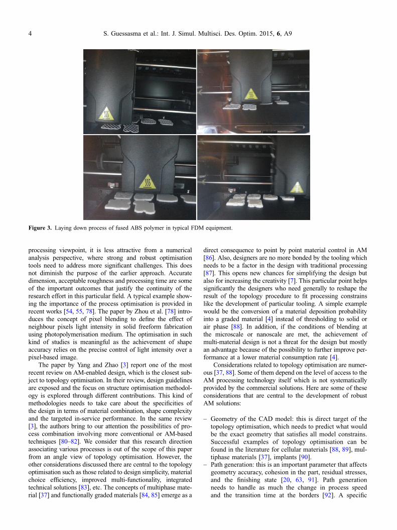
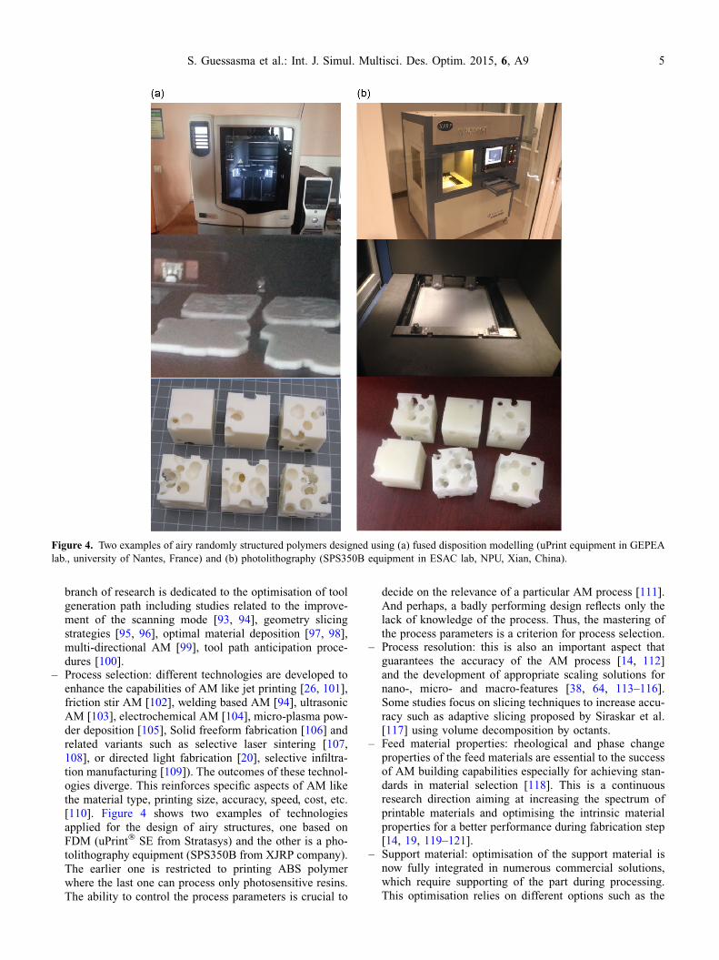
– Process selection: different technologies are developed toenhance the capabilities of AM like jet printing [26, 101],friction stir AM [102], welding based AM [94], ultrasonicAM [103], electrochemical AM [104], micro-plasma pow-der deposition [105], Solid freeform fabrication [106] andrelated variants such as selective laser sintering [107,108], or directed light fabrication [20], selective infiltra-tion manufacturing [109]). The outcomes of these technol-ogies diverge. This reinforces specific aspects of AM likethe material type, printing size, accuracy, speed, cost, etc.[110]. Figure 4 shows two examples of technologiesapplied for the design of airy structures, one based onFDM (uPrint� SE from Stratasys) and the other is a pho-tolithography equipment (SPS350B from XJRP company).The earlier one is restricted to printing ABS polymerwhere the last one can process only photosensitive resins.The ability to control the process parameters is crucial to
decide on the relevance of a particular AM process [111].And perhaps, a badly performing design reflects only thelack of knowledge of the process. Thus, the mastering ofthe process parameters is a criterion for process selection.
– Process resolution: this is also an important aspect thatguarantees the accuracy of the AM process [14, 112]and the development of appropriate scaling solutions fornano-, micro- and macro-features [38, 64, 113–116].Some studies focus on slicing techniques to increase accu-racy such as adaptive slicing proposed by Siraskar et al.[117] using volume decomposition by octants.
– Feed material properties: rheological and phase changeproperties of the feed materials are essential to the successof AM building capabilities especially for achieving stan-dards in material selection [118]. This is a continuousresearch direction aiming at increasing the spectrum ofprintable materials and optimising the intrinsic materialproperties for a better performance during fabrication step[14, 19, 119–121].
– Support material: optimisation of the support material isnow fully integrated in numerous commercial solutions,which require supporting of the part during processing.This optimisation relies on different options such as the
Figure 4. Two examples of airy randomly structured polymers designed using (a) fused disposition modelling (uPrint equipment in GEPEAlab., university of Nantes, France) and (b) photolithography (SPS350B equipment in ESAC lab, NPU, Xian, China).
S. Guessasma et al.: Int. J. Simul. Multisci. Des. Optim. 2015, 6, A9 5

smart deposition for which only reduced amount of sup-port material is needed [76]. Some research works stillcontribute in this particular area to improve the spatial dis-tribution of airy support material [75, 122].
The logic behind topology optimisation is illustrated inFigure 5. The geometry of the CAD model can be somethingto discover through the optimisation procedure or assisted byimaging tools such as micro-CT scanning [123]. Since the opti-misation combines physical and geometrical constrains,numerical solutions need to be available to predict what wouldbe the result of the part performance [14, 112]. This is gener-ally addressed using finite element computation [53]. Thenumerical model needs to converge in all design situationswithin a short time because the process is meant to be repeatedseveral times. Depending on the nature of the physical con-strain, the numerical model can be more or less sophisticated.
For instance, residual stress analysis requires most of the timesolving a multi-physics problems [124, 125]. If numericalmodels are able to handle technological, physical, and geomet-rical constrains, design guidelines can be adopted by couplingthe optimisation tool to decision making paradigms.Some studies show that AM process simulation is possible[125, 126] but the ultimate goal would be to bridge suchrealistic tools with the optimisation paradigm. Recent worksprove unfortunately that we are far from such ideal situation[127].
Topology optimisation needs to cope with the specificitiesof AM. As this process generates a complex network of 3Ddefects, numerical models need to integrate the result of defectin the analysis as an implicit performance perturbation orexplicit defect influence. This is the main difference betweenthe two schemes presented in Figure 5. The classical scheme(Figure 5a) does not handle the defects induced by processing,
Figure 5. (a) Classical view of topological optimisation, (b) Modified scheme with defect sensitive topology optimisation of AM.
6 S. Guessasma et al.: Int. J. Simul. Multisci. Des. Optim. 2015, 6, A9

which makes any deviation from the optimal virtual design acause of failure. Numerical sizing in aerospace applications[128] is a typical example where such defects can be an issueto validate the final design in airframe development. In the sec-ond scheme (Figure 5b), the corrections introduced by themonitoring of the defects helps in guiding the optimisation tooltowards the best realistic solution. This resolution is directlyrelated to the AM tooling constrains, for instance the choiceof the tip size. If the second scheme is used to consider appro-priate selection for tooling options (like nozzle diameter), thensuch process parameter can be considered as a discrete vari-able. Optimal design can be searched in a larger space depend-ing on the possibilities offered to select a certain number ofavailable nozzles. Real-time control of AM like the opticaltomography [129, 130], thermographic analysis [131] or ultra-sonic monitoring [132, 133] helps in gaining valuable informa-tion about the structural defects that develop during AMprocessing and their direct consequence on failure of thedesigned part [73]. This is still a challenging issue as it appearsthat adequate non-destructive techniques are not yet fully avail-able to evaluate properly AM part performance [52]. This sit-uation can be improved through the development of standardswhich is still an ongoing process for the validation of testingtechniques applicable to AM [134]. One of the most promisingtechniques to analyse microstructural defects in AM parts isX-ray micro-tomography [135]. This technique is able to pro-vide precise information about the porous network induced byprocessing, surface roughness, part volume, amount of supportmaterial and any other microstructural defect [27]. As the tech-nique relies on transformation of 2D projections into 3D image[136, 137], structural anisotropy effects can be quantified.
Figure 6 shows two examples of defects revealed in ABSpolymer printed using fused deposition modelling. Cross-sec-tion views refer to a dense block of ABS (30 · 30 · 30mm3) analysed using X-ray micro-tomography. This block isoriented at 0� in the printing plateau, but we notice clearlythe crossing of filaments at an angle of 45� and the presenceof bounding layer. In Figure 6a, the resolution of the imageis 1077 · 1062 · 1059 voxels, where a voxel is a graphicalunit in 3D. The physical size of the voxel determines the accu-racy of the structural defect evaluation. In Figure 5a, the voxelsize is 30 lm. More information about the operating condi-tions can be found in reference [27]. Figure 5a shows the lackof cohesion between successive filaments and tendency to flat-tening because the filament diameter is tripled during the lay-ing down of the fused matter. The subsequent porosity forms asa regular network of micro-sized defects, and appears to behighly connected. Also, residual support material can be foundat the borders, which reveals difficulties of support materialremoval. The automatic cleaning process is generally followedby manual removal step to ensure that no residual supportmaterial is left behind. The second example highlighted inFigure 6b shows other imperfections that infiltrate the designof a two phase material. These imperfections are related to dis-continuities of matter in the cell walls, the change of geometrydue to design mismatch effects and the presence of supportmaterial trapped in closed pores of small size.
In several contributions, the red links in Figure 5b areignored as if the approximate result of the optimisation isunavoidably accepted. More recent contributions tackle suchlinks by suggesting corrections of the design based on manu-facturability considerations [64]. This is performed, however,
Figure 6. Microstructural defects in ABS polymer printed using FDM. Analysis is performed using X-ray micro-tomography. Two examplesare shown one is (a) a dense ABS block and the other is (b) airy ABS materials exhibiting more than 60% of porosity.
S. Guessasma et al.: Int. J. Simul. Multisci. Des. Optim. 2015, 6, A9 7

independently from the optimisation tool itself and does notinvolve defects induced by processing.
3 Challenges for AM topology optimisation
One of the important issues that topology optimisationneeds to address is the pertinence of the constitutive laws rep-resenting the behaviour of the printed materials. Unfortunately,material law implementation is not yet fully revisited leavingan open area for research in this direction [138]. A typicalresearch direction would be to explore interfacial effect interms of limited load transfer and damage kinetics at the lightof results achieved for composite materials [139, 140]. Thisdirection is fully justified by the fact that lack of performanceis more associated to the weak adhesion between filaments.Thus, failure mechanisms are likely to be affected by thearrangement of such weak regions [27].
Another concern is the embedding of the microstructuraldetails in the topology optimisation. During the past decades,this opportunity to tune microstructurally the design was outof reach because of computation resource limitations. Now,this is accessible at the cost of using efficient paradigms thatavoid unrealistic configurations and constrain the search vol-ume to design-effective solutions. Recent experimentalachievements show the potential of AM to tune locally the per-formance of multi-material parts [39]. The next realistic stepwould be to promote this kind of experimental attempts to fullyautomated procedures. The role of microstructural details canbe even determinant in hierarchical structures. Indeed, previousstudies show large possibilities of airy arrangement usinghybrid optimisation strategies [141]. One can imagine the largepossibilities of pore connectivity tailoring driven by AM ifmicro-porosity is considered.
Topology optimisation is not yet ready to provide sys-tematic process error detection for AM. We know that AMprocesses are exposed to inaccuracy in terms of geometryimperfections, volume mismatch, and undesirable surfacetexture. All these drawbacks can be properly addressed bya tool that apprehends the limits of the AM processing. Real-istic designs with acceptable defects are better than idealdesigns with unmeasurable bias. Figure 7 shows some cluesabout how topology optimisation can achieve a higher sensi-tivity to defects in AM. A better understanding of the AMdefects is a matter of scaling down the numerical model tothe size of heterogeneities that are the birth sites of the pro-cess-induced defects. Explicit implementation of discontinu-ities can be handled as well as lack of bonding betweenlayers or filaments. Also more elaborated constitutive lawscan be considered in order to take into account anisotropiesthat are subsequent to the rapid cooling and stretching of thematter.
A straight-A learning paradigm is not also accessible fortopology optimisation. The near future developments will meetsubstantial use of in-situ or in-line monitoring procedures forAM [16, 142]. Topology optimisation can integrate some ofthese procedures to learn from the design. This requires thecombination with another class of algorithms that are derivedfrom artificial intelligence [143]. As an end, the optimal designcan be performed using optimal process parameters, whichsaves a considerable amount of time.
A bigger tool for higher perspectives is what process man-agers expect from optimisation tools. Topology optimisationcan be part of it if other considerations are handled carefullylike cost effectiveness with a large material catalogue, materialsaving logics, automated process selection, scenarios of durabil-ity, recyclability and projections of life time. Fully automateddecision making processes can be then launched starting fromthe idea of design to the post-mortem step of the AM part.
Acknowledgements. The authors would like to thank Omar BenHassana, Pierre Malige and Julien Grison, from IUT of Nantes, andKaike Yang from ESAC lab, NPU for their technical assistance onthe 3D printing process and mechanical testing. The authors grate-fully acknowledge the International Campus on Safety and Intermo-dality in Transportation (CISIT), the Nord-Pas-de-Calais Region andthe European Community (FEDER funds) for partly funding theX-ray tomography equipment. The authors are thankful to IBSM fed-eration for the financial support and to the Nord-Pas-de-CalaisRegion (France) for funding Hedi Nouri’s post-doctoral grant (contractNo 14002212). The second author, ZHANG Weihong, thanks the sup-port by National Natural Science Foundation of China (11432011).
References
1. Yan X, Gu P. 1996. A review of rapid prototyping technologiesand systems. Computer-Aided Design, 28(4), 307–318.
2. Pham DT, Gault RS. 1998. A comparison of rapid prototypingtechnologies. International Journal of Machine Tools &Manufacture, 38(10–11), 1257–1287.
3. Yang S, Zhao YF. 2015. Additive manufacturing-enableddesign theory and methodology: a critical review.International Journal of Advanced Manufacturing Technology,80(1–4), 327–342.
Figure 7. Towards modelling of AM process.
8 S. Guessasma et al.: Int. J. Simul. Multisci. Des. Optim. 2015, 6, A9

4. Chiu WK, Yu KM. 2008. Direct digital manufacturing ofthree-dimensional functionally graded material objects.Computer-Aided Design, 40(12), 1080–1093.
5. Shim JH, Kim AJ, Park JY, Yi N, Kang I, Park J, Rhie JW, ChoDW. 2013. Effect of solid freeform fabrication-based polyc-aprolactone/poly(lactic-co-glycolic acid)/collagen scaffoldson cellular activities of human adipose-derived stem cellsand rat primary hepatocytes. Journal of Materials Science-Materials in Medicine, 24(4), 1053–1065.
6. Huang SH, Liu P, Mokasdar A, Hou L. 2013. Additivemanufacturing and its societal impact: a literature review.International Journal of Advanced Manufacturing Technology,67(5–8), 1191–1203.
7. Zhai YW, Lados DA, Lagoy JL. 2014. Additive manufactur-ing: making imagination the major limitation. JOM, 66(5),808–816.
8. Schelly C, Anzalone G, Wijnen B, Pearce JM. 2015. Open-source 3-D printing technologies for education: bringingadditive manufacturing to the classroom. Journal of VisualLanguages and Computing, 28, 226–237.
9. Gress DR, Kalafsky RV. 2015. Geographies of production in3D: theoretical and research implications stemming fromadditive manufacturing. Geoforum, 60, 43–52.
10. Kietzmann J, Pitt L, Berthon P. 2015. Disruptions, decisions,and destinations: enter the age of 3-D printing and additivemanufacturing. Business Horizons, 58(2), 209–215.
11. Shirazi SFS, Gharehkhani S, Mehrali M, Yarmand H, MetselaarHSC, Kadri NA, Abu Osman NA. 2015. A review on powder-based additive manufacturing for tissue engineering: selectivelaser sintering and inkjet 3D printing. Science and Technologyof Advanced Materials, 16(3), 033502-1–033502-20.
12. Turner BN, Gold SA. 2015. A review of melt extrusionadditive manufacturing processes: II. Materials, dimensionalaccuracy, and surface roughness. Rapid Prototyping Journal,21(3), 250–261.
13. Gong XB, Anderson T, Chou K. 2012. Review on powder-based electron beam additive manufacturing technology.Proceedings of the ASME/ISCIE International Symposiumon Flexible Automation, Isfa 2012, St. Louis, Missouri, USA,507–515.
14. Huang Y, Leu MC, Mazumder J, Donmez A. 2015. Additivemanufacturing: current state, future potential, gaps and needs,and recommendations. Journal of Manufacturing Science andEngineering-Transactions of the ASME, 137(1), 014001-1–014001-10.
15. Frazier WE. 2014. Metal additive manufacturing: a review.Journal of Materials Engineering and Performance, 23(6),1917–1928.
16. Tapia G, Elwany A. 2014. A review on process monitoring andcontrol in metal-based additive manufacturing. Journal ofManufacturing Science and Engineering-Transactions of theASME, 136(6), 060801-1–060801-10.
17. Vayre B, Vignat F, Villeneuve F. 2012. Metallic additivemanufacturing: state-of-the-art review and prospects. Mechan-ics & Industry, 13(2), 89–96.
18. Nie B, Yang LM, Huang H, Bai S, Wan P, Liu J. 2015.Femtosecond laser additive manufacturing of iron and tung-sten parts. Applied Physics A-Materials Science & Process-ing, 119(3), 1075–1080.
19. Finke S, Feenstra FK. 2002. Solid freeform fabrication byextrusion and deposition of semi-solid alloys. Journal ofMaterials Science, 37(15), 3101–3106.
20. Milewski JO, Dickerson PG, Nemec RB, Lewis GK, FonsecaJC. 1999. Application of a manufacturing model for theoptimization of additive processing of Inconel alloy 690.Journal of Materials Processing Technology, 91(1–3), 18–28.
21. Xu W, Brandt M, Sun S, Elambasseril J, Liu Q, Latham K, XiaK, Qian M. 2015. Additive manufacturing of strong andductile Ti-6Al-4V by selective laser melting via in situmartensite decomposition. Acta Materialia, 85, 74–84.
22. Tang HP, Yang GY, Jia WP, He WW, Lu SL, Qian M. 2015.Additive manufacturing of a high niobium-containing tita-nium aluminide alloy by selective electron beam melting.Materials Science and Engineering A-Structural MaterialsProperties Microstructure and Processing, 636, 103–107.
23. Deckers J, Vleugels J, Kruthl JP. 2014. Additive manufactur-ing of ceramics: a review. Journal of Ceramic Science andTechnology, 5(4), 245–260.
24. Chappell WJ, Reilly C, Halloran J, Katehi LPB. 2003.Ceramic synthetic substrates using solid freeform fabrication.IEEE Transactions on Microwave Theory and Techniques,51(3), 752–760.
25. Tang HH, Yen HC. 2015. Slurry-based additive manufacturingof ceramic parts by selective laser burn-out. Journal of theEuropean Ceramic Society, 35(3), 981–987.
26. Gaytan SM, Cadena MA, Karim H, Delfin D, Lin Y, EspalinD, MacDonald E, Wicker RB. 2015. Fabrication of bariumtitanate by binder jetting additive manufacturing technology.Ceramics International, 41(5), 6610–6619.
27. Guessasma S, Belhabib S, Nouri H. 2015. Significance of porepercolation to drive anisotropic effects of 3D printed polymersrevealed with X-ray l-tomography and finite element com-putation. Polymer, 81, 29–36.
28. Shaffer S, Yang KJ, Vargas J, Di Prima MA, Voit W. 2014. Onreducing anisotropy in 3D printed polymers via ionizingradiation. Polymer, 55(23), 5969–5979.
29. Hatzenbichler M, Geppert M, Seemann R, Stampfl J. 2013.Additive manufacturing of photopolymers using the texasinstruments DLP lightcrafter. Emerging Digital MicromirrorDevice Based Systems and Applications V, 8618, 86180A-1–86180A-8.
30. Puppi D, Mota C, Gazzarri M, Dinucci D, Gloria A,Myrzabekova M, Ambrosio L, Chiellini F. 2012. Additivemanufacturing of wet-spun polymeric scaffolds for bone tissueengineering. Biomedical Microdevices, 14(6), 1115–1127.
31. Quan Z, Wu A, Keefe M, Qin X, Yu J, Suhr J, Byun J-H, KimB-S, Chou T-W. 2015. Additive manufacturing of multidirec-tional preforms for composites: opportunities and challenges.Materials Today, 18, 503–512.
32. Ning FD, Cong WL, Qiu JJ, Wei JH, Wang SR. 2015. Additivemanufacturing of carbon fiber reinforced thermoplastic com-posites using fused deposition modeling. Composites Part B-Engineering, 80, 369–378.
33. Gu DD, Chang F, Dai DH. 2015. Selective laser meltingadditive manufacturing of novel aluminum based compositeswith multiple reinforcing phases. Journal of ManufacturingScience and Engineering-Transactions of the ASME, 137(2).
34. Tekinalp HL, Kunc V, Velez-Garcia GM, Duty CE, Love LJ,Naskar AK, Blue CA, Ozcan S. 2014. Highly oriented carbonfiber-polymer composites via additive manufacturing. Com-posites Science and Technology, 105, 144–150.
35. Lee JS, Cha HD, Shim JH, Jung JW, Kim JY, Cho DW. 2012.Effect of pore architecture and stacking direction on mechan-ical properties of solid freeform fabrication-based scaffold for
S. Guessasma et al.: Int. J. Simul. Multisci. Des. Optim. 2015, 6, A9 9

bone tissue engineering. Journal of Biomedical MaterialsResearch Part A, 100A(7), 1846–1853.
36. Sa AME, Mello VM, Echavarria KR, Covill D. 2015. Adaptivevoids primal and dual adaptive cellular structures for additivemanufacturing. Visual Computer, 31(6–8), 799–808.
37. Takezawa A, Kobashi M, Kitamura M. 2015. Porous com-posite with negative thermal expansion obtained by photo-polymer additive manufacturing. APL Materials, 3(7),076103-1–076103-6.
38. Watjen AM, Gingter P, Kramer M, Telle R. 2014. Novelprospects and possibilities in additive manufacturing ofceramics by means of direct inkjet printing. Advances inMechanical Engineering, 2014, 141346.
39. Sugavaneswaran M, Arumaikkannu G. 2014. Modelling forrandomly oriented multi material additive manufacturing com-ponent and its fabrication. Materials & Design, 54, 779–785.
40. Herderick ED. 2015. Progress in additive manufacturing.JOM, 67(3), 580–581.
41. Giannatsis J, Dedoussis V. 2009. Additive fabrication tech-nologies applied to medicine and health care: a review.International Journal of Advanced Manufacturing Technology,40(1–2), 116–127.
42. Vaezi M, Seitz H, Yang SF. 2013. A review on 3D micro-additive manufacturing technologies. International Journal ofAdvanced Manufacturing Technology, 67(5–8), 1721–1754.
43. Venekamp NJR, Le Fever HT. 2015. Application areas ofadditive manufacturing from curiosity to application. IEEETechnology and Society Magazine, 34(3), 81–87.
44. Lipton JI, Cutler M, Nigi F, Cohen D, Lipson H. 2015.Additive manufacturing for the food industry. Trends in FoodScience & Technology, 43(1), 114–123.
45. Heinrich A, Maillard P, Suckow A, Grzesiak A, Sorg P, BergerU. 2015. Additive manufacturing – a new approach forindividualized optical shape metrology. Optical MeasurementSystems for Industrial Inspection Ix, 9525, 95251T-1–95251T-10.
46. Dickson MN. 2015. Soft strain sensors fabricated throughadditive manufacturing. MRS Bulletin, 40(6), 463.
47. Setaki F, Tenpierik M, Turrin M, van Timmeren A. 2014.Acoustic absorbers by additive manufacturing. Building andEnvironment, 72, 188–200.
48. Ho CMB, Ng SH, Yoon YJ. 2015. A review on 3D printedbioimplants. International Journal of Precision Engineeringand Manufacturing, 16(5), 1035–1046.
49. Butscher A, Bohner M, Hofmann S, Gauckler L, Muller R.2011. Structural and material approaches to bone tissueengineering in powder-based three-dimensional printing. ActaBiomaterialia, 7(3), 907–920.
50. Cox SC, Thornby JA, Gibbons GJ, Williams MA, Mallick KK.2015. 3D printing of porous hydroxyapatite scaffolds intendedfor use in bone tissue engineering applications. MaterialsScience & Engineering C-Materials for Biological Applica-tions, 47, 237–247.
51. Jiang CP, Chen YY, Hsieh MF, Lee HM. 2013. Solid freeformfabrication and in-vitro response of osteoblast cells of mPEG-PCL-mPEG bone scaffolds. Biomedical Microdevices, 15(2),369–379.
52. Waller JM, Saulsberry RL, Parker BH, Hodges KL, Burke ER,Taminger KM. 2015. Summary of NDE of Additive Manu-facturing Efforts in NASA. 41st Annual Review of Progress inQuantitative Nondestructive Evaluation, Vol. 34, 1650, 51–62.
53. Zhu WJ, Zhao XL, Zhang W, Ren K, Zhang ZY, Li DC. 2014.Design and evaluation of fully configured models built byadditive manufacturing. AIAA Journal, 52(7), 1441–1451.
54. Zhu J-H, Zhang W-H, Xia L. 2015. Topology optimization inaircraft and aerospace structures design. Archives of Compu-tational Methods in Engineering, 1–28.
55. Gu XJ, Zhu JH, Zhang WH. 2012. The lattice structureconfiguration design for stereolithography investment castingpattern using topology optimization. Rapid Prototyping Jour-nal, 18(5), 353–361.
56. Engstrom DS, Porter B, Pacios M, Bhaskaran H. 2014.Additive nanomanufacturing – a review. Journal of MaterialsResearch, 29(17), 1792–1816.
57. Chakraborty D, Reddy BA, Choudhury AR. 2008. Extruderpath generation for curved layer fused deposition modeling.Computer-Aided Design, 40(2), 235–243.
58. Lee CS, Kim SG, Kim HJ, Ahn SH. 2007. Measurement ofanisotropic compressive strength of rapid prototyping parts.Journal of Materials Processing Technology, 187, 627–630.
59. Ahn SH, Montero M, Odell D, Roundy S, Wright PK. 2002.Anisotropic material properties of fused deposition modelingABS. Rapid Prototyping Journal, 8(4), 248–257.
60. Lee PH, Chung H, Lee SW, Yoo J, Ko J. 2014. Review:dimensional accuracy in additive manufacturing processes.Proceedings of the ASME 9th International ManufacturingScience and Engineering Conference, 2014, Detroit, Michi-gan, USA, vol. 1, V001T04A045.
61. Zhu YY, Tian XJ, Li J, Wang HM. 2015. The anisotropy oflaser melting deposition additive manufacturing Ti-6.5Al-3.5Mo-1.5Zr-0.3Si titanium alloy. Materials & Design, 67,538–542.
62. Rosa B, Mognol P, Hascoet JY. 2015. Laser polishing ofadditive laser manufacturing surfaces. Journal of LaserApplications, 27, S29102-1–S29102-7.
63. Pinto JM, Arrieta C, Andia ME, Uribe S, Ramos-Grez J,Vargas A, Irarrazaval P, Tejos C. 2015. Sensitivity analysis ofgeometric errors in additive manufacturing medical models.Medical Engineering & Physics, 37(3), 328–334.
64. Nelaturi S, Kim W, Kurtoglu T. 2015. Manufacturabilityfeedback and model correction for additive manufacturing.Journal of Manufacturing Science and Engineering-Transac-tions of the ASME, 137(2), 021015-1–021015-9.
65. Wang T, Zhu YY, Zhang SQ, Tang HB, Wang HM. 2015.Grain morphology evolution behavior of titanium alloycomponents during laser melting deposition additive manu-facturing. Journal of Alloys and Compounds, 632, 505–513.
66. Ma Y, Cuiuri D, Hoye N, Li HJ, Pan ZX. 2015. The effect oflocation on the microstructure and mechanical properties oftitanium aluminides produced by additive layer manufacturingusing in-situ alloying and gas tungsten arc welding. MaterialsScience and Engineering A-Structural Materials PropertiesMicrostructure and Processing, 631, 230–240.
67. Hong C, Gu DD, Dai DH, Alkhayat M, Urban W, Yuan PP,Cao S, Gasser A, Weisheit A, Kelbassa I, Zhong ML, PopraweR. 2015. Laser additive manufacturing of ultrafine TiCparticle reinforced Inconel 625 based composite parts: tailoredmicrostructures and enhanced performance. Materials Scienceand Engineering A-Structural Materials Properties Micro-structure and Processing, 635, 118–128.
68. Carroll BE, Palmer TA, Beese AM. 2015. Anisotropic tensilebehavior of Ti-6Al-4V components fabricated with directed
10 S. Guessasma et al.: Int. J. Simul. Multisci. Des. Optim. 2015, 6, A9

energy deposition additive manufacturing. Acta Materialia,87, 309–320.
69. Thrimurthulu K, Pandey PM, Reddy NV. 2004. Optimum partdeposition orientation in fused deposition modeling. InternationalJournal of Machine Tools & Manufacture, 44(6), 585–594.
70. Rua Y, Muren R, Reckinger S. 2015. Limitations of additivemanufacturing on microfluidic heat exchanger components.Journal of Manufacturing Science and Engineering-Transac-tions of the ASME, 137(3), 034504-1–034504-5.
71. Carneiro OS, Silva AF, Gomes R. 2015. Fused depositionmodeling with polypropylene. Materials & Design, 83, 768–776.
72. Scudino S, Unterdorfer C, Prashanth KG, Attar H, Ellendt N,Uhlenwinkel V, Eckert J. 2015. Additive manufacturing of Cu-10Sn bronze. Materials Letters, 156, 202–204.
73. Foster BK, Reutzel EW, Nassar AR, Dickman CJ, Hall BT.2015. A brief survey of sensing for metal-based powder bedfusion additive manufacturing. Dimensional Optical Metrol-ogy and Inspection for Practical Applications Iv, 9489,94890B-1–94890B-9.
74. Furumoto T, Koizumi A, Alkahari MR, Anayama R, Hosok-awa A, Tanaka R, Ueda T. 2015. Permeability and strength ofa porous metal structure fabricated by additive manufacturing.Journal of Materials Processing Technology, 219, 10–16.
75. Hu KL, Jin S, Wang CCL. 2015. Support slimming for singlematerial based additive manufacturing. Computer-AidedDesign, 65, 1–10.
76. Jin YA, He Y, Fu JZ. 2015. Support generation for additivemanufacturing based on sliced data. International Journal ofAdvanced Manufacturing Technology, 80(9–12), 2041–2052.
77. Mohamed OA, Masood SH, Bhowmik JL. 2015. Optimizationof fused deposition modeling process parameters: a review ofcurrent research and future prospects. Advances in Manufac-turing, 3(1), 42–53.
78. Zhou C, Chen Y, Waltz RA. 2009. Optimized mask imageprojection for solid freeform fabrication. Journal of Manu-facturing Science and Engineering-Transactions of the ASME,131(6), 061004-1–061004-12.
79. Garg A, Lam JSL, Savalani MM. 2015. A new computationalintelligence approach in formulation of functional relationshipof open porosity of the additive manufacturing process.International Journal of Advanced Manufacturing Technology,80(1–4), 555–565.
80. Mun J, Yun BG, Ju J, Chang B. 2015. Indirect additivemanufacturing based casting of a periodic 3D cellular metal –flow simulation of molten aluminum alloy. Journal ofManufacturing Processes, 17, 28–40.
81. Giannitelli SM, Mozetic P, Trombetta M, Rainer A. 2015.Combined additive manufacturing approaches in tissue engi-neering. Acta Biomaterialia, 24, 1–11.
82. Rogers CM, Morris GE, Gould TWA, Bail R, Toumpaniari S,Harrington H, Dixon JE, Shakesheff KM, Segal J, Rose FRAJ.2014. A novel technique for the production of electrospunscaffolds with tailored three-dimensional micro-patternsemploying additive manufacturing. Biofabrication, 6(3),035003.
83. Newman ST, Zhu ZC, Dhokia V, Shokrani A. 2015. Processplanning for additive and subtractive manufacturing technolo-gies. CIRP Annals-Manufacturing Technology, 64(1), 467–470.
84. Jin GQ, Li WD. 2013. Adaptive rapid prototyping/manufac-turing for functionally graded material-based biomedicalmodels. International Journal of Advanced ManufacturingTechnology, 65(1–4), 97–113.
85. Zhou MY, Xi JT, Yan JQ. 2004. Modeling and processing offunctionally graded materials for rapid prototyping. Journal ofMaterials Processing Technology, 146(3), 396–402.
86. Roper DA, Good BL, McCauley R, Yarlagadda S, Smith J,Good A, Pa P, Mirotznik MS. 2014. Additive manufacturingof graded dielectrics. Smart Materials and Structures, 23(4),045029.
87. Becker R, Grzesiak A, Henning A. 2005. Rethink assemblydesign. Assembly Automation, 25(4), 262–266.
88. Zhang P, Toman J, Yu Y, Biyikli E, Kirca M, Chmielus M, ToAC. 2015. Efficient design-optimization of variable-densityhexagonal cellular structure by additive manufacturing: theoryand validation. Journal of Manufacturing Science and Engi-neering-Transactions of the ASME, 137(2), 021004-1–021004-8.
89. Yang L, Harrysson O, West H, Cormier D. 2015. Mechanicalproperties of 3D re-entrant honeycomb auxetic structuresrealized via additive manufacturing. International Journal ofSolids and Structures, 69–70, 475–490.
90. Chen JN, Ahmad R, Suenaga H, Li W, Sasaki K, Swain M, LiQ. 2015. Shape optimization for additive manufacturing ofremovable partial dentures – a new paradigm for prostheticCAD/CAM. PLos One, 10(7), 0132552.
91. Denlinger ER, Heigel JC, Michaleris P, Palmer TA. 2015.Effect of inter-layer dwell time on distortion and residualstress in additive manufacturing of titanium and nickel alloys.Journal of Materials Processing Technology, 215, 123–131.
92. Thompson B, Yoon HS. 2014. Efficient path planningalgorithm for additive manufacturing systems. IEEE Trans-actions on Components Packaging and Manufacturing Tech-nology, 4(9), 1555–1563.
93. Kim HC, Choi KH, Doh YH, Kim DS. 2009. Fabrication ofparts and their evaluation using a dual laser in the solidfreeform fabrication system. Journal of Materials ProcessingTechnology, 209(10), 4857–4866.
94. Ding DH, Pan ZX, Cuiuri D, Li HJ. 2015. Wire-feed additivemanufacturing of metal components: technologies, develop-ments and future interests. International Journal of AdvancedManufacturing Technology, 81(1–4), 465–481.
95. Ren L, Sparks T, Ruan JZ, Liou F. 2008. Process planningstrategies for solid freeform fabrication of metal parts. Journalof Manufacturing Systems, 27(4), 158–165.
96. Paul R, Anand S. 2015. A new Steiner patch based file formatfor additive manufacturing processes. Computer-AidedDesign, 63, 86–100.
97. Xu AP, Shaw LL. 2005. Equal distance offset approach torepresenting and process planning for solid freeform fabrica-tion of functionally graded materials. Computer-AidedDesign, 37(12), 1308–1318.
98. Ding DH, Pan ZX, Cuiuri D, Li HJ. 2015. A multi-beadoverlapping model for robotic wire and arc additive manu-facturing (WAAM). Robotics and Computer-Integrated Man-ufacturing, 31, 101–110.
99. Song X, Pan YY, Chen Y. 2015. Development of a low-costparallel kinematic machine for multidirectional additivemanufacturing. Journal of Manufacturing Science and Engi-neering-Transactions of the ASME, 137(2), 021005-1–021005-13.
100. Arntz K, Wegener M, Liu Y. 2015. Computer aided manu-facturing supported process planning of additive manufactur-ing by laser deposition welding. Journal of LaserApplications, 27, S14002-1–S14002-5.
S. Guessasma et al.: Int. J. Simul. Multisci. Des. Optim. 2015, 6, A9 11

101. Seifert T, Sowade E, Roscher F, Wiemer M, Gessner T,Baumann RR. 2015. Additive manufacturing technologiescompared: morphology of deposits of silver ink using inkjetand aerosol jet printing. Industrial & Engineering ChemistryResearch, 54(2), 769–779.
102. Palanivel S, Nelaturu P, Glass B, Mishra RS. 2015. Frictionstir additive manufacturing for high structural performancethrough microstructural control in an Mg based WE43 alloy.Materials & Design, 65, 934–952.
103. Monaghan T, Capel AJ, Christie SD, Harris RA, Friel RJ.2015. Solid-state additive manufacturing for metallized opti-cal fiber integration. Composites Part A-Applied Science andManufacturing, 76, 181–193.
104. Sundaram MM, Kamaraj AB, Kumar VS. 2015. Mask-lesselectrochemical additive manufacturing: a feasibility study.Journal of Manufacturing Science and Engineering-Transac-tions of the ASME, 137(2), 021006-1–021006-9.
105. Wang H, Jiang W, Valant M, Kovacevic R. 2003. Microplasmapowder deposition as a new solid freeform fabrication process.Proceedings of the Institution of Mechanical Engineers PartB-Journal of Engineering Manufacture, 217(12), 1641–1650.
106. Leong KF, Cheah CM, Chua CK. 2003. Solid freeformfabrication of three-dimensional scaffolds for engineeringreplacement tissues and organs. Biomaterials, 24(13), 2363–2378.
107. Cai K, Guo D, Huang Y, Yang JL. 2003. Solid freeformfabrication of alumina ceramic parts through a lost mouldmethod. Journal of the European Ceramic Society, 23(6), 921–925.
108. Guo D, Cai K, Nan C, Li LT, Gul ZL. 2002. Gelcasting basedsolid freeform fabrication of piezoelectric ceramic objects.Scripta Materialia, 47(6), 383–387.
109. Sohn H, Yang DY. 2002. Selective infiltration of superheatedmicro-sized droplets of a tin-lead alloy into a preheatedpowder layer for a novel solid freeform fabrication process.Journal of Materials Science Letters, 21(21), 1717–1719.
110. Mancanares CG, Zancul ED, da Silva JC, Miguel PAC. 2015.Additive manufacturing process selection based on parts’selection criteria. International Journal of Advanced Manu-facturing Technology, 80(5–8), 1007–1014.
111. Price S, Cheng B, Lydon J, Cooper K, Chou K. 2014. Onprocess temperature in powder-bed electron beam additivemanufacturing: process parameter effects. Journal of Manu-facturing Science and Engineering-Transactions of the ASME,136(6), 061019-1–061019-10.
112. Wei C, Dong JY. 2014. Development and modeling of meltelectrohydrodynamic-jet printing of phase-change inks forhigh-resolution additive manufacturing. Journal of Manufac-turing Science and Engineering-Transactions of the ASME,136(6), 061010-1–061010-7.
113. Kang HW, Seol YJ, Cho DW. 2009. Development of anindirect solid freeform fabrication process based on micro-stereolithography for 3D porous scaffolds. Journal of Mi-cromechanics and Microengineering, 19(1), 015011.
114. Mondrinos MJ, Dembzynski R, Lu L, Byrapogu VKC,Wootton DM, Lelkes PI, Zhou J. 2006. Porogen-based solidfreeform fabrication of polycaprolactone-calcium phosphatescaffolds for tissue engineering. Biomaterials, 27(25),4399–4408.
115. Choi H, Yang Y, Li XC. 2005. Experimental study onintegration of laser-based additive/subtractive processes formeso/micro solid freeform fabrication. International Journalof Advanced Manufacturing Technology, 26(4), 335–341.
116. Yoshida H, Igarashi T, Obuchi Y, Takami Y, Sato J, Araki M,Miki M, Nagata K, Sakai K, Igarashi S. 2015. Architecture-scale human-assisted additive manufacturing. ACM Transac-tions on Graphics, 34(4), 88.
117. Siraskar N, Paul R, Anand S. 2015. Adaptive slicing inadditive manufacturing process using a modified boundaryoctree data structure. Journal of Manufacturing Science andEngineering-Transactions of the ASME, 137(1), 011007-1–011007-11.
118. Slotwinski JA, Garboczi EJ, Stutzman PE, Ferraris CF, WatsonSS, Peltz MA. 2014. Characterization of metal powders usedfor additive manufacturing. Journal of Research of theNational Institute of Standards and Technology, 119, 460–493.
119. Sakar-Deliormanli A, Celik E, Polat M. 2008. Rheologicalbehavior of PMN gels for solid freeform fabrication. Colloidsand Surfaces A-Physicochemical and Engineering Aspects,324(1–3), 159–166.
120. Yen HC. 2015. Experimental studying on development ofslurry-layer casting system for additive manufacturing ofceramics. International Journal of Advanced ManufacturingTechnology, 77(5–8), 915–925.
121. Shiva S, Palani IA, Mishra SK, Paul CP, Kukreja LM. 2015.Investigations on the influence of composition in the devel-opment of Ni-Ti shape memory alloy using laser basedadditive manufacturing. Optics and Laser Technology, 69,44–51.
122. Strano G, Hao L, Everson RM, Evans KE. 2013. A newapproach to the design and optimisation of support structuresin additive manufacturing. International Journal of AdvancedManufacturing Technology, 66(9–12), 1247–1254.
123. Cooper D, Thornby J, Blundell N, Henrys R, Williams MA,Gibbons G. 2015. Design and manufacture of high perfor-mance hollow engine valves by additive layer manufacturing.Materials & Design, 69, 44–55.
124. Zohdi TI. 2015. Modeling and simulation of cooling-inducedresidual stresses in heated particulate mixture depositions inadditive manufacturing. Computational Mechanics, 56(4),613–630.
125. Bai XW, Zhang HO, Wang GL. 2015. Modeling of the movinginduction heating used as secondary heat source in weld-basedadditive manufacturing. International Journal of AdvancedManufacturing Technology, 77(1–4), 717–727.
126. Brant AM, Sundaram MM, Kamaraj AB. 2015. Finite elementsimulation of localized electrochemical deposition for mask-less electrochemical additive manufacturing. Journal of Man-ufacturing Science and Engineering-Transactions of theASME, 137(1), 011018-1–011018-9.
127. Kranz J, Herzog D, Emmelmann C. 2015. Design guidelinesfor laser additive manufacturing of lightweight structures inTiAl6V4. Journal of Laser Applications, 27, S14001-1–S14001-16.
128. Grihon S, Krog L, Bassir D. 2011. Numerical optimizationapplied to structure sizing at AIRBUS: a multi-step process.International Journal for Simulation and MultidisciplinaryDesign Optimization, 3(4), 432–442.
129. Zenzinger G, Bamberg J, Ladewig A, Hess T, Henkel B,Satzger W. 2015. Process monitoring of additive manufactur-ing by using optical tomography. 41st Annual Review ofProgress in Quantitative Nondestructive Evaluation, Vol. 34,1650, 164–170.
130. Carl V. 2015. Monitoring system for the quality assessment inadditive manufacturing. 41st Annual Review of Progress in
12 S. Guessasma et al.: Int. J. Simul. Multisci. Des. Optim. 2015, 6, A9

Quantitative Nondestructive Evaluation, Vol. 34, 1650, 171–176.
131. Krauss H, Zeugner T, Zaeh MF. 2015. Thermographic processmonitoring in powderbed based additive manufacturing. 41stAnnual Review of Progress in Quantitative NondestructiveEvaluation, Vol. 34, 1650, 177–183.
132. Rieder H, Dillhofer A, Spies M, Bamberg J, Hess T. 2015.Ultrasonic online monitoring of additive manufacturingprocesses based on selective laser melting. 41st AnnualReview of Progress in Quantitative Nondestructive Evalua-tion, Vol. 34, 1650, 184–191.
133. Everton S, Dickens P, Tuck C, Dutton B. 2015. Evaluation oflaser ultrasonic testing for inspection of metal additivemanufacturing. Laser 3d Manufacturing Ii, 9353, 935316-1–935316-8.
134. Monzon MD, Ortega Z, Martinez A, Ortega F. 2015.Standardization in additive manufacturing: activities carriedout by international organizations and projects. InternationalJournal of Advanced Manufacturing Technology, 76(5–8),1111–1121.
135. Raguvarun K, Balasubramaniam K, Rajagopal P, PalanisamyS, Nagarajah R, Hoye N, Curiri D, Kapoor A. 2015. A study ofinternal structure in components made by additive manufac-turing process using 3D X-ray tomography. 41st AnnualReview of Progress in Quantitative Nondestructive Evalua-tion, Vol. 34, 1650, 146–155.
136. Guessasma S, Nouri H. 2015. Compression behaviour ofbread crumb up to densification investigated using X-raytomography and finite element computation. Food ResearchInternational, 72, 140–148.
137. Ayadi A, Nouri H, Guessasma S, Roger F. 2015. An originalapproach to assess elastic properties of a short glass fibrereinforced thermoplastic combining X-ray tomography andfinite element computation. Composite Structures, 125, 277–286.
138. Adamczak S, Bochnia J, Kaczmarska B. 2015. An analysis oftensile test results to assess the innovation risk for an additivemanufacturing technology. Metrology and Measurement Sys-tems, 22(1), 127–138.
139. Guessasma S, Bassir DH. 2010. Identification of mechanicalproperties of biopolymer composites sensitive to interfaceeffect using hybrid approach. Mechanics of Materials, 42(3),344–353.
140. Hbib M, Guessasma S, Bassir D, Benseddiq N. 2011.Interfacial damage in biopolymer composites reinforced usinghemp fibres: finite element simulation and experimentalinvestigation. Composites Science and Technology, 71(11),1419–1426.
141. Guessasma S, Bassir D. 2010. Optimization of the mechanicalproperties of virtual porous solids using a hybrid approach.Acta Materialia, 58(2), 716–725.
142. Xiong J, Zhang GJ. 2014. Adaptive control of deposited heightin GMAW-based layer additive manufacturing. Journal ofMaterials Processing Technology, 214(4), 962–968.
143. Witherell P, Feng S, Simpson TW, Saint John DB, MichalerisP, Liu ZK, Chen LQ, Martukanitz R. 2014. Toward meta-models for composable and reusable additive manufacturingprocess models. Journal of Manufacturing Science andEngineering-Transactions of the ASME, 136(6), 061025-1–061025-9.
Cite this article as: Guessasma S, Zhang W, Zhu J, Belhabib S & Nouri H: Challenges of additive manufacturing technologies froman optimisation perspective. Int. J. Simul. Multisci. Des. Optim., 2015, 6, A9.
S. Guessasma et al.: Int. J. Simul. Multisci. Des. Optim. 2015, 6, A9 13