Embed Size (px)
Citation preview
The Measurement of Residual Stresses
A modification of the Sachs "boring-out" method is used to measure residual stress present in gas tungsten-arc welds made in Hastelloy N
BY A. G. CEPOLINA AND D. A. CANONICO
ABSTRACT. A modification of the Sachs "boring-out" method for determining residual stresses has been developed. This technique permits the determination of the distribution of the stresses and their levels over extremely short increments of distances. This technique was used for measuring the residual stresses present in gas tungsten-arc welds made in Hastelloy N, an alloy that is currently being employed in the Molten Salt Reactor Experiment.
The specimen was 1/i in. thick plate, 12 in. in diameter. Circular welds 6 in. in diameter were simultaneously deposited on both flat faces. The equations applicable for the calculation of residual stresses in this specimen geometry are as follows:
<TT — <TR -\-Rda
where aR = radial stress and aT = tangential stress.
We found that the maximum value of tangential residual stress was about 50,000 psi and was not particularly affected by either the shielding gas or heat input. Stress relieving at 1600° F for 4.5 hr proved to be the optimum heat treatment and reduced the tangential residual stress to about 5000 psi. Lowering of the maximum residual stress to about 10,000 psi was achieved at 1400° F after 6 hr; however, lower temperatures even for times as long as 100 hr only reduced the maximum residual stress by about 25%.
Introduction The existence of residual stresses in
fabricated structures is an undisputed fact. Even after stress relief, their presence at some low value is frequently assumed. Although the existence of residual stresses is accepted, their role in the serviceability of a structure is open to debate. In riveted or bolted joints and in the autofrettage process, they have recognized beneficial effects. Moreover, in welded structures, their
A. G. CEPOLINA, formerly of the Oak Ridge National Laboratory, is currently residing in Italy and D. A. CANONICO is in the Metals and Ceramics Division of Oak Ridge National Laboratory, Oak Ridge, Tenn.
effect is contradictory. The Ship Structure Committee1 in 1947 stated that locked-in stresses do not contribute materially to failure (in regard to World War II ship failures). In contrast, in a review by a subcommittee2 of the ASME, it was implied that the residual stress adds to the applied stress to initiate fast fracture. This same subcommittee did point out, however, that the simple additiveness of the stresses has been questioned.
Support for the position of the additiveness of applied and residual stresses is made by Week.3 He states that, in the presence of residual stresses, the static strength and carrying capacity of a structure are affected by yielding at applied loads lower in magnitude than those causing yielding in a stress-free structure. Barton and Hall4 showed that the presence of a residual strain field materially aided the initiation and propagation processes in their plane plate-fracture studies. They also showed that a compressive stress field had the opposite effect—that is, it behaved as a crack-arrest site.
Hence, the greater portion of evidence is that residual stress, particularly in a strain-sensitive material, can affect the initiation and propagation of a failure at stresses below those normally considered in design. However, it is also evident that the residual stress can be beneficial, even under the same circumstances if they are compressive and thereby behave as a crack arrestor. Therefore, a treatise concerned with residual stress must consider both the magnitude of the stress and its distribution.
Our understanding of the role of residual stresses is minimal even today. The problem was recognized in the Nuclear Safety Information Center Report5 No. 21. Here it was stated that "It is apparent that further research is needed regarding the effects of these stresses." The only way this request can be satisfied is through improved techniques for measuring the stress of interest.
Residual Stresses Residual stresses in welded structures
are due to two main sources, mechanical working and thermal excursions. A third source, due to phase transformations, is common only to materials that undergo an allotropic transformation during their thermal excursions. Mechanical working of a structure is to some degree controllable by taking some care during fitup, etc. Welded joints, however, cannot avoid differential thermal expansion during welding and these are the stresses of primary concern. The magnitude of the forces generated due to thermal expansion can be approximated from the following equation6:
a = EaAT
where a = the stress generated, psi; a - the coefficient of thermal expansion, CC)"1; E = the modulus of elasticity, psi; and AT = the temperature difference, °C.
Stresses of 50,000 psi (yield point magnitude for a number of low-alloy high-strength steels) are produced in components containing temperature differences of only 300° F. It does not take much imagination to appreciate that temperature differences of these levels readily exist during welding. At high temperatures, the molten puddle serves as a source into which the metal can expand. The subsequent freezing of the molten pool is not deleterious until temperatures are reached wherein the strength of the metal is sufficiently high to restrict plastic flow. At this point, residual stresses are produced. Further cooling only affects the distribution of these stresses and not their magnitude. It is these stresses, their magnitudse, and distribution that are of concern in this paper.
Development of the Technique for Measuring Residual Stresses Selection of Technique
We have undertaken this investigation of residual stresses using a modifica-
W E L D I N G R E S E A R C H S U P P L E M E N T I 31-s
tion of the Sachs "boring-out" technique. The original modification was suggested by Gilliland, Smith, and Jones at ORNL and subsequently applied by Adams and Corrigan7 in the investigation of residual stresses in submarine hull steels. In this paper, we discuss a further modification and refinement of the technique.
It is unique in that it permits the essentially continuous determination of the magnitude and distribution of residual stresses across the entire weldment. This is in contrast to the more frequently utilized techniques of pre-placing strain gauges and subsequently freeing them from the more massive samples.8 This latter technique provides useful data; however, it is limited by its areal coverage. It provides only one data point per strain gauge and is applicable over the rather large area covered by the gauge itself. Consequently, the strain readings obtained are really an integrated average for the area covered by the gauge and provided only a discontinuous stress distribution.
Other than the modified Sachs "boring-out" method, only the X-ray scattering technique appears to provide a potential for continuous determination of residual stresses; however, its practicality and accuracy for specimens of this size are questionable,
The technique employed in this study was originally developed by Sachs for analyzing the rotational triaxial residual stress distribution in bars and pipes9 and recently was applied in the plane stress version for studying residual stresses in weldments.7 In its most elementary form, it consists of removing, by machining, portions of a simple disk, thereby releasing the locked-in stresses. The relaxation of these stresses produces a measurable elastic deformation from which these stresses can be computed through the application of the appropriate equations.
Derivation of Equations
The determination of residual stresses rotationally distributed about the center of the solid thin disk is possible by the progressive circumferential removal of finite elements starting from an initially drilled hole at the disk axis. If the material removal is correlated with a corresponding change in the circumference of the rim of the disk, then the stress at any point within this disk can be calculated. These calculations can be accomplished by applying the classical solution for a flat disk in which there exists a plane stress symmetrically distributed about its center. The stress function <p (after Timoshenko10) for such a case is defined as follows:
<f> = A log R + BR2 log R + CR2 + D
where A, B, C, and D are constants and R is the radius. Differentiating the above
equation provides: Then, at the outside radius R = R0;
(TR =
0~ 1
l_cty _A_ RdR ~ R2
+ B(\ +2\o%R) +2C (1)
dl_ _A_ dR2 R2
+ B (3 + 2 log R) + 2C (2)
where oR = radial stress at location R; and aT = tangential stress at location R.
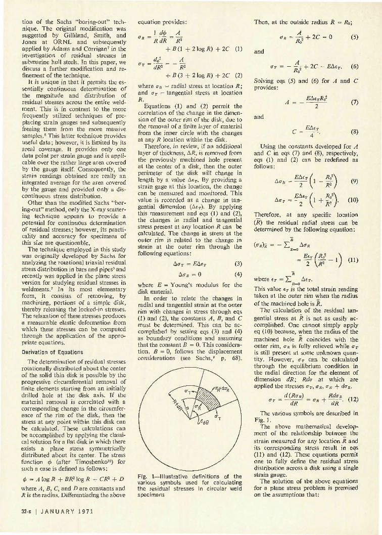
Equations (1) and (2) permit the correlation of the change in the dimension of the outer rim of the disk, due to the removal of a finite layer of material from the inner circle with the changes at any R location within the disk.
Therefore, in review, if an additional layer of thickness, AR, is removed from the previously machined hole present at the center of a disk, then the outer perimeter of the disk will change in length by a value AeT. By providing a strain gage at this location, the change can be measured and monitored. This value is recorded as a change in tangential dimension (AtT). By applying this measurement and eqs (1) and (2), the changes in radial and tangential stress present at any location R can be calculated. The change in stress at the outer rim is related to the change in strain at the outer rim through the following equations:
Ac T = EAtT
AD* = 0
(3)
(4)
where E = Young's modulus for the disk material.
In order to relate the changes in radial and tangential strain at the outer rim with changes in stress through eqs (1) and (2), the constants A, B, and C must be determined. This can be accomplished by setting eqs (3) and (4) as boundary conditions and assuming that the constant B = 0. This consideration, B = 0, follows the displacement considerations (see Sachs,9 p. 68).
Fig. 1—Illustrative definitions of the various symbols used for calculating the residual stresses in circular weld specimens
<r 8 =^+2C = q (5)
and
OT —.+2C = EAtT. (6)
Solving eqs (5) and (6) for A and C provides:
EAtTR02
and
C = EAt7
(7)
(8)
Using the constants developed for A and C in eqs (7) and (8), respectively, eqs (1) and (2) can be redefined as follows:
AaR =
Ao> =
EAt 2
EAt
(-10 '('+t>
(9)
(10)
Therefore, at any specific location (R) the residual radial stress can be determined by the following equation:
(O-R)R Z A<7R
Et. 2 (JH ai)
where tT = X) A*sj*. s*=o
This value tT is the total strain reading taken at the outer rim when the radius of the machined hole is R.
The calculation of the residual tangential stress at R is not as easily accomplished. One cannot simply apply eq (10) because, when the radius of the machined hole R coincides with the outer rim, <JR is fully relieved while a> is still present at some unknown quantity. However, oT can be calculated through the equilibrium condition in the radial direction for the element of dimension dR; Rda at which are applied the stresses oT, aR, oR + doR.
d(RrjR) RdaR
"-—or -*»+-*»-• <12> The various symbols are described in
Fig. 1. The above mathematical develop
ment of the relationship between the strain measured for any location R and its corresponding stress result in eqs (11) and (12). These equations permit one to fully define the residual stress distribution across a disk using a single strain gauge.
The solution of the above equations for a plane stress problem is premised on the assumptions that:
32-s | J A N U A R Y 1 9 7 1
Wi
P ' *
f; Pr K. ; '•. 1 : i \ '*-•-' Ui../;-.. •
s V:
T " "*'
i
V
5' f'7 - ? - i ; .
f i
"•> ' '
|
T -
/ ' . ; '
. ,
•«* M S - . ] rii?**3
py :'?
gti
- |i;i;i
P|;S "1 M •", ••'$
f f i | *;* .;*< V i f i,4,- ' i "%'
H.m - "... ),£,
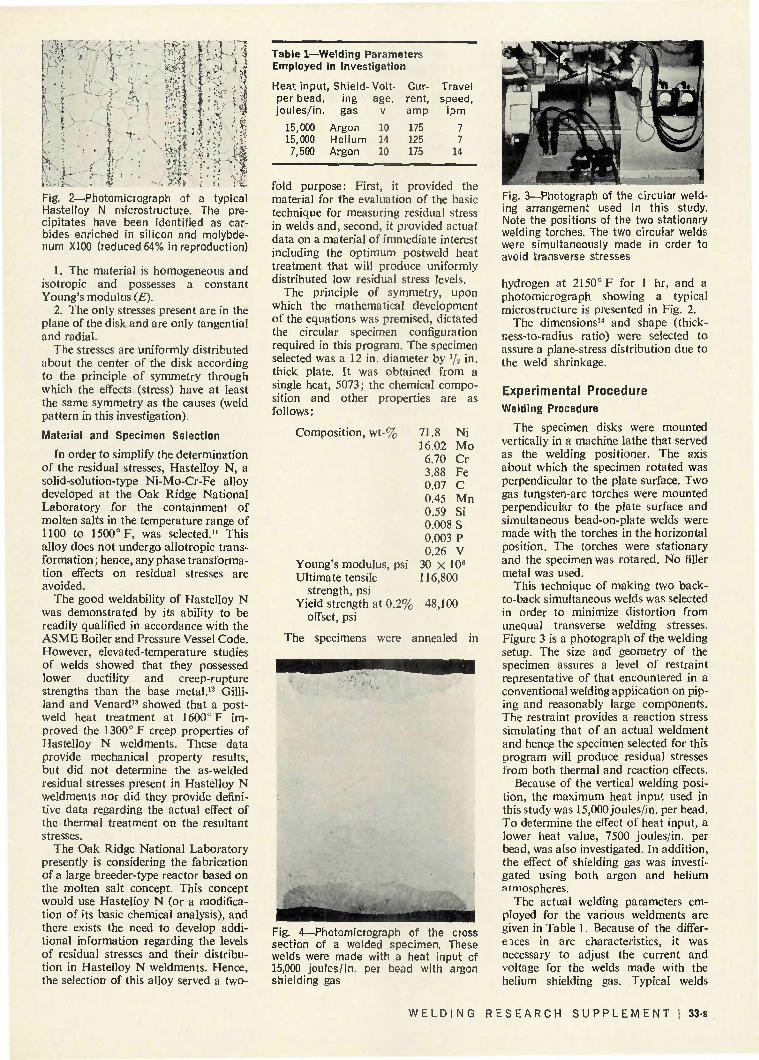
Fig. 2—Photomicrograph of a typical Hastelloy N microstructure. The precipitates have been identified as carbides enriched in silicon and molybdenum XlOO (reduced 64% in reproduction)
1. The material is homogeneous and isotropic and possesses a constant Young's modulus (E).
2. The only stresses present are in the plane of the disk and are only tangential and radial.
The stresses are uniformly distributed about the center of the disk according to the principle of symmetry through which the effects (stress) have at least the same symmetry as the causes (weld pattern in this investigation).
Material and Specimen Selection
In order to simplify the determination of the residual stresses, Hastelloy N, a solid-solution-type Ni-Mo-Cr-Fe alloy developed at the Oak Ridge National Laboratory for the containment of molten salts in the temperature range of 1100 to 1500° F, was selected.11 This alloy does not undergo allotropic transformation ; hence, any phase transformation effects on residual stresses are avoided.
The good weldability of Hastelloy N was demonstrated by its ability to be readily qualified in accordance with the ASME Boiler and Pressure Vessel Code. However, elevated-temperature studies of welds showed that they possessed lower ductility and creep-rupture strengths than the base metal.12 Gilliland and Venard13 showed that a postweld heat treatment at 1600° F improved the 1300° F creep properties of Hastelloy N weldments. These data provide mechanical property results, but did not determine the as-welded residual stresses present in Hastelloy N weldments nor did they provide definitive data regarding the actual effect of the thermal treatment on the resultant stresses.
The Oak Ridge National Laboratory presently is considering the fabrication of a large breeder-type reactor based on the molten salt concept. This concept would use Hastelloy N (or a modification of its basic chemical analysis), and there exists the need to develop additional information regarding the levels of residual stresses and their distribution in Hastelloy N weldments. Hence, the selection of this alloy served a two-
age, v 10 14 10
rent, amp 175 125 175
speed, ipm
7 7
14
Table 1—Welding Parameters Employed in Investigation
Heat input, Shield-Volt- Cur- Travel per bead, ing joules/in. gas
15,000 Argon 15,000 Helium 7,500 Argon
fold purpose: First, it provided the material for the evaluation of the basic technique for measuring residual stress in welds and, second, it provided actual data on a material of immediate interest including the optimum postweld heat treatment that will produce uniformly distributed low residual stress levels.
The principle of symmetry, upon which the mathematical development of the equations was premised, dictated the circular specimen configuration required in this program. The specimen selected was a 12 in. diameter by 1/2 in. thick plate. It was obtained from a single heat, 5073; the chemical composition and other properties are as follows :
Composition, wt-% 71.8 Ni 16.02 Mo 6.70 Cr 3.88 Fe 0.07 C 0.45 Mn 0.59 Si 0.008 S 0.003 P 0.26 V
Young's modulus, psi 30 X 106
Ultimate tensile 116,800 strength, psi
Yield strength at 0.2% 48,100 offset, psi
The specimens were annealed in
Fig. 4—Photomicrograph of the cross section of a welded specimen. These welds were made with a heat input of 15,000 joules/in. per bead with argon shielding gas
Fig. 3—Photograph of the circular welding arrangement used in this study. Note the positions of the two stationary welding torches. The two circular welds were simultaneously made in order to avoid transverse stresses
hydrogen at 2150° F for 1 hr, and a photomicrograph showing a typical microstructure is presented in Fig. 2.
The dimensions14 and shape (thick-uess-to-radius ratio) were selected to assure a plane-stress distribution due to the weld shrinkage.
Experimental Procedure Welding Procedure
The specimen disks were mounted vertically in a machine lathe that served as the welding positioner. The axis about which the specimen rotated was perpendicular to the plate surface. Two gas tungsten-arc torches were mounted perpendicular to the plate surface and simultaneous bead-on-plate welds were made with the torches in the horizontal position. The torches were stationary and the specimen was rotared. No filler metal was used.
This technique of making two back-to-back simultaneous welds was selected in order to minimize distortion from unequal transverse welding stresses. Figure 3 is a photograph of the welding setup. The size and geometry of the specimen assures a level of restraint representative of that encountered in a conventional welding application on piping and reasonably large components. The restraint provides a reaction stress simulating that of an actual weldment and henqe the specimen selected for this program will produce residual stresses from both thermal and reaction effects.
Because of the vertical welding position, the maximum heat input used in this study was 15,000 joules/in. per bead. To determine the effect of heat input, a lower heat value, 7500 joules/in. per bead, was also investigated. In addition, the effect of shielding gas was investigated using both argon and helium atmospheres.
The actual welding parameters employed for the various weldments are given in Table 1. Because of the differ-e ices in arc characteristics, it was necessary to adjust the current and voltage for the welds made with the helium shielding gas. Typical welds
WELDING RESEARCH SUPPLEMENT! 33-s
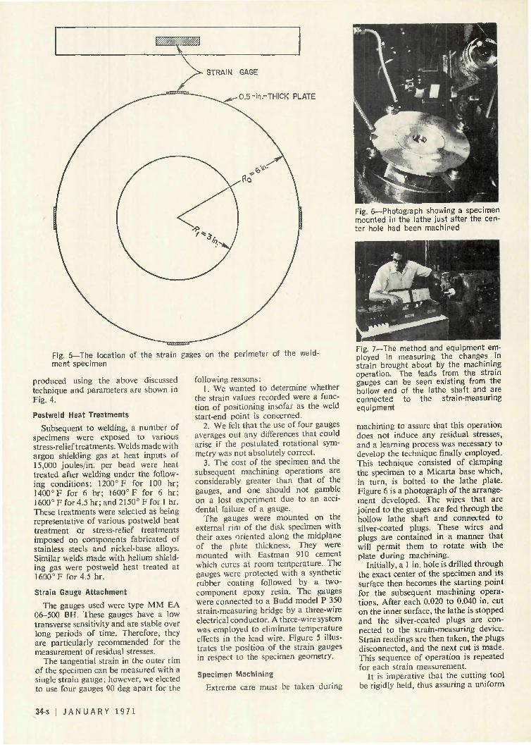
0.5-in.-THICK PLATE
Fig. 5—The location of the strain gages on the perimeter of the weldment specimen
produced using the above discussed technique and parameters are shown in Fig. 4.
Postweld Heat Treatments
Subsequent to welding, a number of specimens were exposed to various stress-relief treatments. Welds made with argon shielding gas at heat inputs of 15,000 joules/in. per bead were heat treated after welding under the following conditions: 1200° F for 100 hr; 1400° F for 6 hr; 1600° F for 6 hr; 1600° Ffor 4.5 hr; and 2150° F for 1 hr. These treatments were selected as being representative of various postweld heat treatment or stress-relief treatments imposed on components fabricated of stainless steels and nickel-base alloys. Similar welds made with helium shielding gas were postweld heat treated at 1600° F for 4.5 hr.
Strain Gauge Attachment
The gauges used were type MM EA 06-500 BH. These gauges have a low transverse sensitivity and are stable over long periods of time. Therefore, they are particularly recommended for the measurement of residual stresses.
The tangential strain in the outer rim of the specimen can be measured with a single strain gauge, however, we elected to use four gauges 90 deg apart for the
following reasons: 1. We wanted to determine whether
the strain values recorded were a function of positioning insofar as the weld start-end point is concerned.
2. We felt that the use of four gauges averages out any differences that could arise if the postulated rotational symmetry was not absolutely correct.
3. The cost of the specimen and the subsequent machining operations are considerably greater than that of the gauges, and one should not gamble on a lost experiment due to an accidental failure of a gauge.
The gauges were mounted on the external rim of the disk specimen with their axes oriented along the midplane of the plate thickness. They were mounted with Eastman 910 cement which cures at room temperature. The gauges were protected with a synthetic rubber coating followed by a two-component epoxy resin. The gauges were connected to a Budd model P 350 strain-measuring bridge by a three-wire electrical conductor. A three-wire system was employed to eliminate temperature effects in the lead wire. Figure 5 illustrates the position of the strain gauges in respect to the specimen geometry.
Specimen Machining
Extreme care must be taken during
Fig. 6—Photograph showing a specimen mounted in the lathe just after the center hole had been machined
Fig. 7—The method and equipment employed in measuring the changes in strain brought about by the machining operation. The leads from the strain gauges can be seen existing from the hollow end of the lathe shaft and are connected to the strain-measuring equipment
machining to assure that this operation does not induce any residual stresses, and a learning process was necessary to develop the technique finally employed. This technique consisted of clamping the specimen to a Micarta base which, in turn, is bolted to the lathe plate. Figure 6 is a photograph of the arrangement developed. The wires that are joined to the gauges are fed through the hollow lathe shaft and connected to silver-coated plugs. These wires and plugs are contained in a manner that will permit them to rotate with the plate during machining.
Initially, a 1 in. hole is drilled through the exact center of the specimen and its surface then becomes the starting point for the subsequent machining operations. After each 0.020 to 0.040 in. cut on the inner surface, the lathe is stopped and the silver-coated plugs are connected to the strain-measuring device. Strain readings are then taken, the plugs disconnected, and the next cut is made. This sequence of operation is repeated for each strain measurement.
It is imperative that the cutting tool be rigidly held, thus assuring a uniform
34-s I J A N U A R Y 1971
quality of cut and minimal work hardening. Voluminous quantities of cutting fluid are used to assure adequate lubrication and cooling during machining. The temperature of the specimen was monitored by a thermocouple during the cutting sequence. The temperature rise was minimal, being approximately 7° F. This alone attests to the quality of the machining operation. In addition, the contact resistance of the silver-coated plugs was measured and found to be insignificant.
Figure 7 is a photograph taken during a strain measurement. The wires from the strain gauges can be seen exciting from the hollow end of the lathe shaft.
Results The tangential residual stress, crr, can
be expressed as a function of tT (tangential strain) and R (the radius of the machined inner hole). In fact, eq (12) can be rewritten as follows:
0"7* = d(RoR)
dR EdtrRl 2 dR R2
- R Ro2 , ,
(13)
In order to determine the incremental change deT/dR as a function of location R, it is necessary to fit the experimentally obtained strain values to a continuous curve. As is evident, this chore can be extremely tedious. However, we were fortunate to be able to smooth the data by a cubic spline system15 that was adaptable to computer techniques. Hence, the data generated were programmed into a computer and the curve fitting and determination of the incremental slopes at their respective radial locations were done with minimal effort. The tangential stresses were then calculated in accordance with eq (13) by the computer as a function of the location R across the weldment.
The radial stresses are also determined by the computer from the longitudinal strain tT.
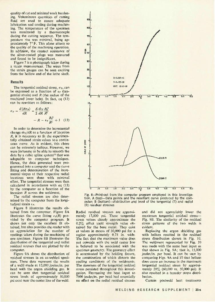
Figure 8 illustrates the results obtained from the computer. Figure 8A illustrates the curve fitting tT(R) provided by the computer program. It shows not only the excellent fit obtained, but also provides the reader with an appreciation for the number of readings taken during the machining of one specimen. Figure 8B illustrates the distribution of the tangential and radial residual stresses that are plotted by the computer.
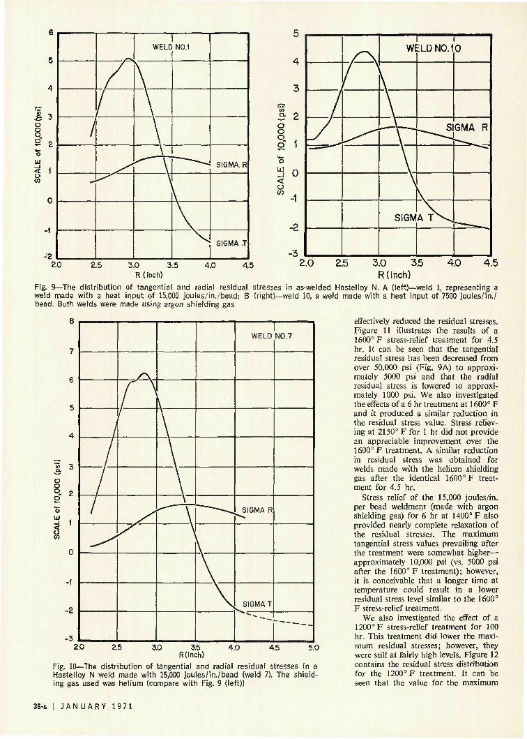
Figure 9A shows the distribution of residual stresses in an as-welded specimen. These data represent the results of a weld made at 15,000 joules/in. per bead with the argon shielding gas. It can be seen that tangential residual stress levels of approximately 50,000 psi exist near the center line of the weld.
S=4.00E-01
P=5.20E-06
DfiTE 02-21-68
Fig. 8—Print-out from the computer program employed in this investigation. A (top)—Data points and the resultant curve produced by the computer; B (bottom)—distribution and level of the tangential (T) and radial (R) residual stresses
Radial residual stresses are approximately 17,000 psi. These tangential stress values closely approximate the 0.2% offset yield strength value obtained for the base metal. They exist at values in excess of 30,000 psi for a region approximately 0.75 in. wide. The fact that the maximum value does not coincide with the weld center line is believed to be associated with the specimen geometry. The geometry effect is accentuated by the holding fixture, the combination of which distorts the cooling conditions of the weldments. The skewness of the tangential residual stress persisted throughout this investigation. Decreasing the heat input to 7500 joules/in. per bead had essentially no effect on the radial residual stresses
and did not appreciably lower the maximum tangential residual stress— Fig. 9B. The similarity of the residual stress patterns of the two welds is evident.
Replacing the argon shielding gas with helium resulted in the residual stress distribution shown in Fig. 10. The weldment represented by Fig. 10 was made with the same heat input as that shown in Fig. 9A; that is, 15,000 joules/in. per bead. It can be seen by comparing Figs. 9A and 10 that helium does cause an increase in the maximum tangential residual stress by approximately 20% (60,000 vs. 50,000 psi). It also resulted in a broader stress distribution.
Certain postweld heat treatments
W E L D I N G R E S E A R C H S U P P L E M E N T ! 35-s
& 3 o o o 2" 2
LU
o CO
-2
1 WELD N0.1
SIGMA R
SIGMA T
3 2 o o o o
o UJ _ l < o in
0
-2
-3
w I ELD NO. 1
- ^ ^ S
SIGMA T ^
I 0
GMA R
2.0 2.5 2.0 2.5 4.0 4.5 3.0 3.5 4.0 4.5 £«U ^-^ 3.0 3.5 R(inch) R(inch)
Fig. 9—The distribution of tangential and radial residual stresses in as-welded Hastelloy N. A (left)—weld 1, representing a weld made with a heat input of 15,000 joules/in./bead; B (right)—weld 10, a weld made with a heat input of 7500 joules/in./ bead. Both welds were made using argon shielding gas
8
o o o o"
< o
WELD
SIGMA R
SIGMA T
^
NO. 7
"— — - -
2.0 2.5 3.0 3.5 R(inch)
4.0 4.5 5.0
Fig. 10—The distribution of tangential and radial residual stresses in a Hastelloy N weld made with 15,000 joules/in./bead (weld 7). The shielding gas used was helium (compare with Fig. 9 (left))
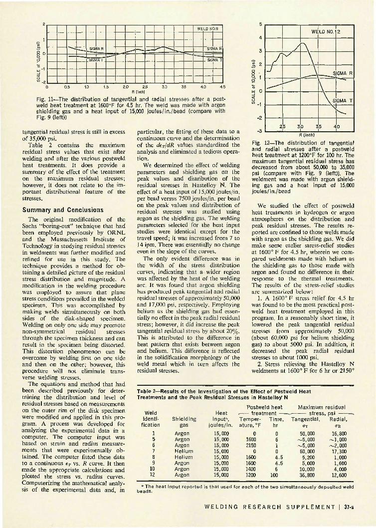
effectively reduced the residual stresses. Figure 11 illustrates the results of a 1600° F stress-relief treatment for 4.5 hr. It can be seen that the tangential residual stress has been decreased from over 50,000 psi (Fig. 9A) to approximately 5000 psi and that the radial residual stress is lowered to approximately 1000 psi. We also investigated the effects of a 6 hr treatment at 1600° F and it produced a similar reduction in the residual stress value. Stress relieving at 2150° F for 1 hr did not provide an appreciable improvement over the 1600° F treatment. A similar reduction in residual stress was obtained for welds made with the helium shielding gas after the identical 1600° F treatment for 4.5 hr.
Stress relief of the 15,000 joules/in. per bead weldment (made with argon shielding gas) for 6 hr at 1400° F also provided nearly complete relaxation of the residual stresses. The maximum tangential stress values prevailing after the treatment were somewhat higher— approximately 10,000 psi (vs. 5000 psi after the 1600° F treatment); however, it is conceivable that a longer time at temperature could result in a lower residual stress level similar to the 1600° F stress-relief treatment.
We also investigated the effect of a 1200° F stress-relief treatment for 100 hr. This treatment did lower the maximum residual stresses; however, they were still at fairly high levels. Figure 12 contains the residual stress distribution for the 1200° F treatment. It can be seen that the value for the maximum
36-s I J A N U A R Y 1971
_ ' SIGMA R ~
1
L SIGMA T
1
1
WELD N0.9
|"SIGMA R
_ SIGMA T
0 0.5 1.0 1.5 2.0 E.5 3.0 35 4.0 4.5 R (inch)
Fig. 11—The distribution of tangential and radial stresses after a postweld heat treatment at 1600°F for 4.5 hr. The weld was made with argon shielding gas and a heat input of 15,000 joules/in./bead (compare with Fig. 9 (left))
tangential residual stress is still in excess of 35,000 psi.
Table 2 contains the maximum residual stress values that exist after welding and after the various postweld heat treatments. It does provide a summary of the effect of the treatment on the maximum residual stresses; however, it does not relate to the important distributional feature of the stresses.
Summary and Conclusions The original modification of the
Sachs "boring-out" technique that had been employed previously by ORNL and the Massachusetts Institute of Technology in studying residual stresses in weldments was further modified and refined for use in this study. The technique provides a method for obtaining a detailed picture of the residual stress distribution and magnitude. A modification in the welding procedure was employed to assure that plane stress conditions prevailed in the welded specimen. This was accomplished by making welds simultaneously on both sides of the disk-shaped specimen. Welding on only one side may promote non-symmetrical residual stresses through the specimen thickness and can result in the specimen being distorted. This distortion phenomenon can be overcome by welding first on one side and then on the other; however, this procedure will not eliminate transverse welding stresses.
The equations and method that had been described previously for determining the distribution and level of residual stresses based on measurements on the outer rim of the disk specimen were modified and applied in this program. A process was developed for analyzing the experimental data in a computer. The computer input was based on strain and radius measurements that were experimentally obtained. The computer fitted these data to a continuous tT vs. R curve. It then made the appropriate calculations and plotted the stress vs. radius curves. Computerizing the mathematical analysis of the experimental data and, in
particular, the fitting of these data to a continuous curve and the determination of the dtT/dR values standardized the analysis and eliminated a tedious operation.
We determined the effect of welding parameters and shielding gas on the peak values and distribution of the residual stresses in Hastelloy N. The effect of a heat input of 15,000 joules/in. per bead versus 7500 joules/in. per bead on the peak values and distribution of residual stresses was studied using argon as the shielding gas. The welding parameters selected for the heat input studies were identical except for the travel speed; it was increased from 7 to 14 ipm. There was essentially no change even in the slope of the curves.
The only evident difference was in the width of the stress distribution curves, indicating that a wider region was affected by the heat of the welding arc. It was found that argon shielding has produced peak tangential and radial residual stresses of approximately 50,000 and 17,000 psi, respectively. Employing helium as the shielding gas had essentially no effect in the peak radial residual stress; however, it did increase the peak tangential residual stress by about 20%. This is attributed to the difference in heat pattern that exists between argon and helium. This difference is reflected in the solidification morphology of the weld metal which in turn affects the residual stresses.
R (inch)
Fig. 12—The distribution of tangential and radial stresses after a postweld heat treatment at 1200°F for 100 hr. The maximum tangential residual stress has decreased from about 50,000 to 35,000 psi (compare with Fig. 9 (left)). The weldment was made with argon shielding gas and a heat input of 15,000 joules/in./bead
We studied the effect of postweld heat treatments in hydrogen or argon atmospheres on the distribution and peak residual stresses. The results reported are confined to those welds made with argon as the shielding gas. We did make some earlier stress-relief studies at 1600° F for 4.5 hr, wherein we compared weldments made with helium as the shielding gas to those made with argon and found no difference in their response to the thermal treatments. The results of the stress-relief studies are summarized below:
1. A 1600° F stress relief for 4.5 hr was found to be the most practical postweld heat treatment employed in this program. In a reasonably short time, it lowered the peak tangential residual stresses from approximately 50,000 (about 60,000 psi for helium shielding gas) to about 5000 psi. In addition, it decreased the peak radial residual stresses to about 1000 psi.
2. Stress relieving the Hastelloy N weldments at 1600° F for 6 hr or 2150°
Table 2— Results of the 1 ivestigation of the Effect of Postweld Heat Treatments and the Peak Residual Stresses in Hastelloy N
Weld identi
fication
1 5 6 7 8 9
10 12
Shielding gas
Argon Argon Argon Helium Helium Argon Argon Argon
Heat input",
joules/in
15,000 15,000 15,000 15,000 15,000 15,000 15,000 15,000
Postweld heat . treatrr Temper-ature,°F
0 1600 2150
0 1600 1600 1400 1200
ent * Time,
hr
0 6 1 0 4.5 4.5 6
100
Maximum . stress Tangential,
0"X
50,000 —5,000 —5,000 60,000 5,200 5,000
10,000 36,800
residual psi . Radial,
a-R
16,800 —1,000 —2,000 17,300 1,000 1,600 4,000
12,600
* The heat input reported is that used for each of the two simultaneously deposited weld beads.
W E L D I N G R E S E A R C H S U P P L E M E N T ! 37-s
F for 1 hr did not provide any appreciable improvement over the 1600° F for 4.5 hr treatment. Indeed, the 2150° F treatment could be detrimental in that it could tend to promote warpage and distortion in a complex structure.
3. Stress relieving the weldments at 1400° F for 6 hr lowered the tangential and radial residual stresses to about 10,000 and 4000 psi, respectively. If a 1600° F temperature is considered to be excessive, it is probable that extended times at 1400° F could provide the required relief of residual stresses. Furthermore, it is quite likely that a 10,000 psi peak tangential residual stress value is acceptable.
4. A 1200° F stress-relief treatment for 100 hr did not prove satisfactory. It lowered the peak tangential and radial residual stresses by only about 25%.
Acknowledgment
The authors would like to express their appreciation to those personnel
who contributed to this program. In particular, G. M. Slaughter, R. G. Gilliland, and J. E. Smith for their suggestions and technical advice, D. E. Arnurius for his computer assistance, J. E. Oliver for his contributions during machining of the specimens, and J. A. Hunt who did the welding
References 1. Welding J. Res. Suppl. 17(15), (1947). 2. Subcommit tee on Br i t t le F r a c t u r e of
the ASME Research Committee on Prevention of F r a c t u r e in Metals, "A Review of Engineer ing Approaches to Design Against F r a c t u r e , " American Society of Mechanical Engineers . 1965.
3. R. Week, "Res idual Stresses Due to Weld ing ," Symposium on In te rna l Stresses in Metals and Alloys, Ins t i tu te of Metals Monograph, London, 1948.
4. F . W. Bar ton and W. J . Hall , "Br i t t le-Fai lure Tests of Six-Foot Wide P r e -stressed Steel P l a t e s . " Welding Journa l 39(9), Research Suppl. 379-s (1960).
5. G. D. Whi tman , G. C. Robinson, J r . , and A. W. Savolainen. Technology of Steel Pressure Vessels for Water-Cooled Nuclear Reactors, ORNL-NSIC-21 (December 1967).
6. K. Heindlhofer, Evaluation of Residual Stresses, McGraw-Hill, New York, 1948.
7. C. L. Adams and D. A. Corrigan,
"Mechanical and Metallurgical Behavior of Rest ra ined Welds in Submar ine Steels ," F ina l Repor t Contract No. Nobs-92077, Project Serial No. SR007-01-01, Task 855, Submit ted to the U. S. Depa r tmen t of the Navy. Bureau of Ships, Washington, D. C.
8. Metals Handbook, 1968 Edit ion, The American Society for Metals, Cleveland, Ohio, p. 237.
9. G. Sachs. " T h e Determina t ion of Residual Stresses in Rods and T u b e s , " Z. Metallic. 19. 352 (1937).
10. S. Timoshenko and J. N. Goodier, Theory of Elasticity, 2nd ed., McGraw-Hill , New York, 1951.
11. H. E. McCoy. J r . , and J . R. Weir , J r . , Materials Development for Molten Salt Breeder Reactors, ORNL-TM-1854, p . 19 (June 1967).
12. H. E. McCoy and D. A. Canonico, "P re i r r ad ia t ion and Pos t i r rad ia t ion Mechanical Proper t ies of Hastel loy N Welds ," Welding J o u r n a l 48(5), Research Suppl. 203-s to 211-s (1969).
13. R. G. Gilliland and J . T. Venard, "Elevated Tempera tu re Mechanical P rop erties of Welds in a Ni-Mo-Cr-Fe Alloy," Welding J o u r n a l 45(3), Research Suppl. 103-s to 110-s (1966).
14. K. Masubuchi. "Effects of Residual Stresses on F r a c t u r e Behavior of Weldm e n t s , " Weld Imperfections, Addison-Wesley Publ ishing Company, 1968.
15. Chris t ian H. Reinsch, "Smoothing by Spline Func t ions , " Teehmsche Hoch-schule Munchen, Matematisches Inst i tut— Rechenzentrum.
Eastern European Welding Research News (Continued from page 30-s)
seam. For the type of bench tested, the quotient of the number of am-pheres turns and the optimum distance transverse to the weld seam amounts to 9-10A/mm.
• Gunther, W. H.: Comparison of two methods for measuring residual stresses (722-27).—The results of measurements obtained with the X-ray method according to Stroppe and with the trepanning method according to Gunnert were compared. The X-ray method gives smoother curves and is recommended for laboratory testing. The trepanning method gives more abrupt readings but is preferred for on-site testing even though it requires considerable skill in handling the testing equipment.
• Muller, K.: Weld quality as a function of the welding process (728-31). —The author proposes a method of quality control involving control cards to arrive at a safe estimate, based on systematic data collected during the initial phase of a production run, of the weld quality to be anticipated in serial production based on a given welding process.
• Huhndorf, P.: Value-engineering applied to a welded structural component (732-38).—Value-engineering is a means of avoiding unnecessary
cost in design and fabrication. By applying the principles of value-engineering, the author attempts to lower the total cost of a given welded structural component.
YUGOSLAVIA Zavarivac 15, No. 1 (Jan.-March
1970)
• Pandrc, V.: Some factors to be considered in the introduction of semiautomatic Co2 are welding (5-20).— The technical and economic advantages of semiautomatic Co2 arc welding compared to other welding processes are discussed and particulars relating to the production of butt and fillet welds in different plate thicknesses are given. Data are also presented on the effect of the welding variables on the productivity of the process and on weld quality.
• Beatovic, B.: The fabrication of hydrogen reactors (20-5).—A brief outline of the most important operations in the fabrication of hydrogen reactors is given and the criteria for selecting base and filler materials from the point of weldability are discussed. Special attention is given to welding procedures and to the problem of
welded pipe connections.
• Ivandic, S.: Welding of tube sheets for boiler plants (55-57).—The application of automatic submerged arc welding in the fabrication of tube sheets for large boiler units is described.
Zavarivac 15, No. 2 (April-June 1970)
• Radovic, A.: The susceptibility of low-alloy high-strength steel to cold shortness (5-14).—The conditions for the formation of cold cracks are analyzed and experimental data on the cold cracking susceptibility of two types of low-alloy steel (tensile strength > 140 kp/mm2 (upon welding with lime ferritic and austenitic filler materials are reported.
• Millicevic, M.: Fabrication of steel jackets for blast furnaces (14-24).— A detailed description of the various stages of fabrication and field erection of a heavy blast furnace jacket. Components prefabricated in the shop are assembled at the site into larger segments before the final assembly is undertaken. The welding procedures range from manual to electroslag welding. Semiautomatic gas-shielded welding is used only for the horizontal girth welds.
38-s | J A N U A R Y 1 9 7 1