Embed Size (px)
Citation preview

The LCLS-II: A New High PowerX-ray FEL Facility at SLAC
Tor Raubenheimer for LCLS-II Project TeamOctober 29th, 2014

2
Linac Coherent Light Source (LCLS) and LCLS-II
2014 Symposium on EUV Lithography: LCLS-II Overview,October 29, 2014
The LCLS is the world’s 1st x-ray Free Electron Laser (FEL)and the LCLS-IIupgrade will bethe 1st CW x-rayFEL (~2020)
High brightnessx-ray sourcespushing theboundaries inphoton sciencesupported byDOE
3
Why is LCLS-II Relevant to EUV Lithography?
2014 Symposium on EUV Lithography: LCLS-II Overview,October 29, 2014
LCLS and LCLS-II FEL’s are designed to operate over the x-ray range 60 – 0.4 Angstrom with mJ’s per pulse.
LCLS-II will have CW superconducting (SCRF) acceleratorsystem based on technology that has been developed aroundthe world
LCLS-II could be operated to generate ~kW at 13.5 nm in annon-optimal configuration
Technology and design concepts being used for LCLS-II couldbe utilized to generate >10 kW in EUV

4
Free Electron Laser (FEL) Primer
2014 Symposium on EUV Lithography: LCLS-II Overview,October 29, 2014
Two primary configurations: low gain oscillator using mirrors orhigh gain single pass amplifier
3 main elements:e- gun,accelerator,& undulator
Physics is relatively simple: transverse motion in undulator allows e-to couple to light; light causes beam to bunch and radiate as N2
rather than N (no need for quantum mechanics).
Lorentz contraction and relativistic Doppler shift of dipole radiationà lr ~ lu / 2g2 and wavelength easily tunable over wide range
Schematic of FEL oscillator

5
Amplifier FEL Characteristics (i)
2014 Symposium on EUV Lithography: LCLS-II Overview,October 29, 2014
Amplifiers can start from a seed or noise (SASE)• Typical SASE bandwidth is ~0.1%; seeded BW >10x smaller• Transverse coherence usually >50%
Generate GW’s of peak power in short pulses <1ps
X-ray Pulse
6
Amplifier FEL Characteristics (ii)
2014 Symposium on EUV Lithography: LCLS-II Overview,October 29, 2014
Pulses are determined by electron beam• LCLS operates at 120 Hzà 100 fs burst every 8 ms with an
average power <1W
Saturated extraction efficiency of laser from electrons is ~0.1%• More possible with high quality beams and tapered undulators• Livermore extracted 34% in 1986 (at 10 cm-wavelength)• LCLS has achieved 0.4% at 5 keV with 6 mJ in a pulse
CW SCRF accelerators can achieve repetition rates limited byRF frequency (ns-bunch spacing) and max beam power• Accelerators (PSI, SLAC, SNS) have operated with MW beams
but do need to be aware of activation and radiation handling

7
Operating Free Electron Lasers
2014 Symposium on EUV Lithography: LCLS-II Overview,October 29, 2014
Over 50 FEL’s operating around the world ranging frommm-wavelength to sub-Angstrom.
• JLAB generated 14 kW in IR in oscillator configuration• LCLS generated 6 mJ in single pulse at a few keV• SACLA has lased at sub-Angstrom wavelengths
Motz, Phillips1950’s
Madey1970’s
Duke Ring1990’s
FLASH2000’s
LCLS, SACLA2010
JLAB2000’s
FEL History – Modified from Colson, 2006

2014 Symposium on EUV Lithography: LCLS-II Overview, October 29,2014
Slide 8
Linac Coherent LightSource Facility
Injector at2-km point
Existing Linac (1 km)(with modifications)
Electron Transfer Line (340 m)
X-ray TransportLine (200 m)
Undulators (130 m)
Near Experiment Hall
Far Experiment Hall
New SCRF linac andinjector in 1st km ofSLAC linac tunnel
and LCLS-II Upgrade(1st light 2019)

9
LCLS-II Accelerator LayoutNew Superconducting Linacà LCLS Undulator Hall
2014 Symposium on EUV Lithography: LCLS-II Overview,October 29, 2014
• Two sources: high rate SCRF linac and 120 Hz Cu LCLS-I linac• North and South undulators can operate simultaneously in any mode
Undulator SC Linac (up to 1 MHz) Cu Linac (up to 120Hz)
North 0.20 - 1.3 keV
South 1.0 - 5.0 keV up to 25 keVhigher peak power pulses
SXU
HXU
proposed FACET-II LCLS-ILCLS-II SC Linac
bypass line m-wall
A-line
B-lineSector-10 Sector-20 Sector-30Sector-0
extension lineL3L2L1
s (m)
spreader

LCLS-II (SCRF) Baseline Parameters
Parameter symbol nominal range unitsElectron Energy Ef 4.0 2.0 - 4.14 GeVBunch Charge Qb 100 10 - 300 pCBunch Repetition Rate in Linac fb 0.62 0 - 0.93 MHzAverage e- current in linac Iavg 0.062 0.001 - 0.3 mAAvg. e- beam power at linac end Pav 0.25 0 - 1.2 MWNorm. rms slice emittance ge^-s 0.45 0.2 - 0.7 mmFinal peak current (at undulator) Ipk 1000 500 - 1500 AFinal slice E-spread (rms, w/heater) sEs 500 125 - 1500 keVRF frequency fRF 1.3 - GHzAvg. CW RF gradient (powered cavities) Eacc 16 - MV/mAvg. Cavity Q0 Q0 2.7e10 1.5 - 6e10 -Photon energy range of SXR (SCRF) Ephot - 0.2 - 1.2 keVPhoton energy range of HXR (SCRF) Ephot - 1 - 5 keV

LCLS-II versus LCLS performance at 120 Hz(LCLS-II Performance between 1 and 25 keV)
HXR provides much shorterphoton wavelength withcomparable pulse energy
Analytic calculations verified with S-2-E modeling
11

LCLS-II High Rate FEL Tuning Range(HXR between 1 and 5 keV; SXR between 0.2 and 1.3 keV)
Analytic calculations verified with S-2-E modeling
Normal operation at 4 GeVcovers photon range ofprimary interest
2 GeV operationincluded for BBA
122014 Symposium on EUV Lithography:LCLS-II Overview, October 29, 2014
13.5 nm radiationwith 2.8 GeV beam

10
100
1000
0 1 2 3 4 5 6 7
X-R
ayPo
wer
[Wat
ts]
Photon Energy [keV]
LCLS-II X-ray Power using SCRF Linac
2014 Symposium on EUV Lithography: LCLS-II Overview,October 29, 2014
SCRF linac can deliver ~1 MHz beam to either undulator• Goal is to provide >20 Watts over wavelength range
- Easily met across photon range 0.2 to 5 keV• Performance above 5 keV is limited
by emittance and energy spread
• XTES is designed tohandle <200 Watts- Studying methods
of turning down FELpower other than therepetition rate
X-ray Power using 4 GeV SCRF Linac
SXR SASE HXR SASE SXR SeededXTES limit
X-ray power goal
Power estimated for100 pC and 120 kW
13
142014 Symposium on EUV Lithography: LCLS-II Overview,October 29, 2014

15
Superconducting RF Cavities
2014 Symposium on EUV Lithography: LCLS-II Overview,October 29, 2014
Backbone of the LCLS-II accelerator are the 9-cell 1.3 GHzsuperconducting rf cavities
Technology developed in Europe and transferred aroundworld. Hundreds have been fabricated in US, Japan, Europe.
~1 meter
LCLS-II and EuXFEL will use ~1200 combined

LCLS-II Cryomodule1.3 GHz, modified for CW operation
2014 Symposium on EUV Lithography: LCLS-II Overview,October 29, 2014
16
Crymodules will be similar to EuXFEL with modifications forCW operation. EuXFEL producing 1 module/per week.

LCLS-II - Linac and Compressor Layout for 4 GeV
Includes 2.2-km RW-wake
2014 Symposium on EUV Lithography: LCLS-II Overview,October 29, 2014
CM01 CM02,03 CM04 CM15 CM16 CM33BC1
E=250 MeVR56=-55 mmsd=1.6 %
BC2E=1600 MeVR56=-37 mmsd=0.38 %
GUN750 keV
LHE=100 MeV
R56=-14.5 mmsd=0.05 %
L0j = **
V0=100 MVIpk=12 A
sz=1.02 mm
L1j =-12.7°V0=211 MVIpk = 12 A
sz=1.02 mm
HLj =-150°
V0=64.7 MV
L2j =-21°
V0=1446 MVIpk=80 A
sz=0.15 mm
L3j =0
V0=2206 MVIpk=1.0 kAsz=9.0 mm
BYP/LTUE=4.0 GeVR56»0.2 mmsd»0.014%> 2.5-km
3.9GHz
Lfj =±34
V0=202 MVIpk=1.0 kAsz=9.0 mm
CM34,35
BC3E=4.0 GeV
R56=0sd=0.13 %
100-pC machine layout: April 24, 2014; v21 ASTRA run; Bunch length Lb is FWHM ** L0 cav. phases: ~(3°, -15°, 0, 0, 0, 0, 15°,0°)
LinacSec.
V0(MV)
j(deg)
Acc.Grad.*(MV/m)
No.Cryo
Mod’s
No.Avail.Cav’s
SpareCav’s
Cav’sper
Amp.L0 100 ** 16.3 1 8 1 1L1 211 -12.7 13.6 2 16 1 1HL -64.7 -150 12.5 2 16 1 1L2 1446 -21.0 15.5 12 96 6 1L3 2206 0 15.7 18 144 9 1Lf 202 ±34 15.7 2 16 1 1

18
RF Power SystemMore than 1MW 1.3 GHz RF power
Each cavity individually powered with 4 kW Solid-State Amplifier• Specified for 0.01% energy stability and 20 fs timing stability
Waveguide distribution system through25’ penetrations into linac tunnel
10 kW SigmaPhi Amp
2014 Symposium on EUV Lithography: LCLS-II Overview,October 29, 2014
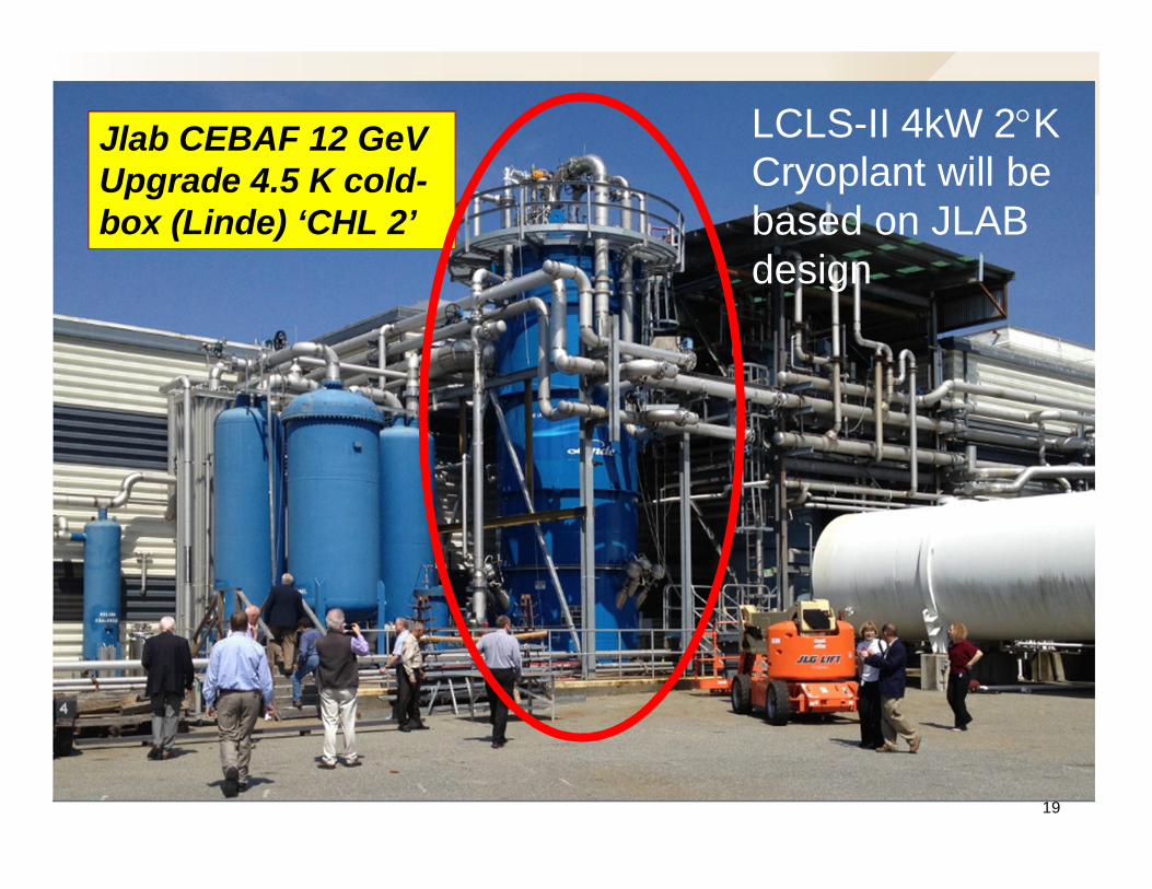
Jlab CEBAF 12 GeVUpgrade 4.5 K cold-box (Linde) ‘CHL 2’
19
LCLS-II 4kW 2°KCryoplant will bebased on JLABdesign

20
FEL Electron Beam Source
2014 Symposium on EUV Lithography: LCLS-II Overview,October 29, 2014
High quality beam is critical for FEL performance• RF guns create beams with sub-micron emittances for low
duty-cycle accelerators• LBNL developing an RF gun for CW operation• Cornell developing an alternate DC gun
2.5 m
750 kV e-beam
LBNL APEX RF gun

21
CW Injector FeasibilityNominal parameters (nearly) demonstrated at Cornell
2014 Symposium on EUV Lithography: LCLS-II Overview,October 29, 2014
C. Guilliford, et al, PRST-AB 16, 073401 (2013)

22
LCLS-II Undulator Layout150 meter existing Undulator Hall
2014 Symposium on EUV Lithography: LCLS-II Overview,October 29, 2014
32 HXU Segments
Existing Diamond CrystalSelf-Seeding System
New SXR Self-SeedingSystem for High Power Loads
21 SXU Segments
Space for future upgradeSpace for polarization
upgrade

23
LCLS-II Undulator Segments
2014 Symposium on EUV Lithography: LCLS-II Overview,October 29, 2014
4.4 m
3.4 m
1.4 m
Beam Position Monitor (RFBPM)Quadrupole (Quad)
Horz/Vert CorrectorsPhase Shifter (PS)
Beam Loss Monitor (BLM)Vacuum Chamber
Earth Field Compensation
Layout shown for two individual undulatorsegments and three break sections for theHXR and SXR undulator lines.
LCLS Undulator hall

Variable Gap Hybrid UndulatorsOngoing Development at LBNL
2014 Symposium on EUV Lithography: LCLS-II Overview,October 29, 2014
Frame
MagneticStructure
Drives
24
Variable gapundulators used inLCLS-II to providegreater wavelengthtuning flexibility
Developing two alternates: Superconductingundulator (SCU) and a Horizontal gapvertically polarized undulator (VPU)

25
High Power CW LinacBeam Collimation and Diagnostics
2014 Symposium on EUV Lithography: LCLS-II Overview,October 29, 2014
• Diagnostics are based on existing designs• Beam power and beam loss issues are critical
- Designing multi-stage collimation system to control losses- Hybrid PM undulators sensitive to nearby losses
• Linac designed for 1.2 MW but undulators limited to 120 kW- 250 kW maximum power through linac in initial phases- Studying dark current and FE effects and radiation limits
• Beam dumps are modified versions of existing MW dumps
HXUHXUSXUSXUSec. 21-30Sec. 21-30
SCRF4 GeV
4 GeV, 100 pC,0.62 MHz, 250 kW4 GeV, 100 pC,0.62 MHz, 250 kW
4 W4 W 120 W120 W
4 GeV, 100 pC,0.62 MHz, 250 kW4 GeV, 100 pC,0.62 MHz, 250 kW
4 GeV, 100 pC,0.30 MHz, 120 kW4 GeV, 100 pC,0.30 MHz, 120 kW
4 GeV, 100 pC,0.30 MHz, 120 kW4 GeV, 100 pC,0.30 MHz, 120 kW

26
MW-class Beam Dumps
2014 Symposium on EUV Lithography: LCLS-IIOverview, October 29, 2014
SLAC has a number of MW beam dumps constructed overdecades of operation
• Require separated water systems with tritium separationand careful treatment of other radionuclides
• Designed to be replaceable
Dual 120 kW Undulator Dumps
30 ft
27
Start-to-End FEL Modeling
2014 Symposium on EUV Lithography: LCLS-II Overview,October 29, 2014
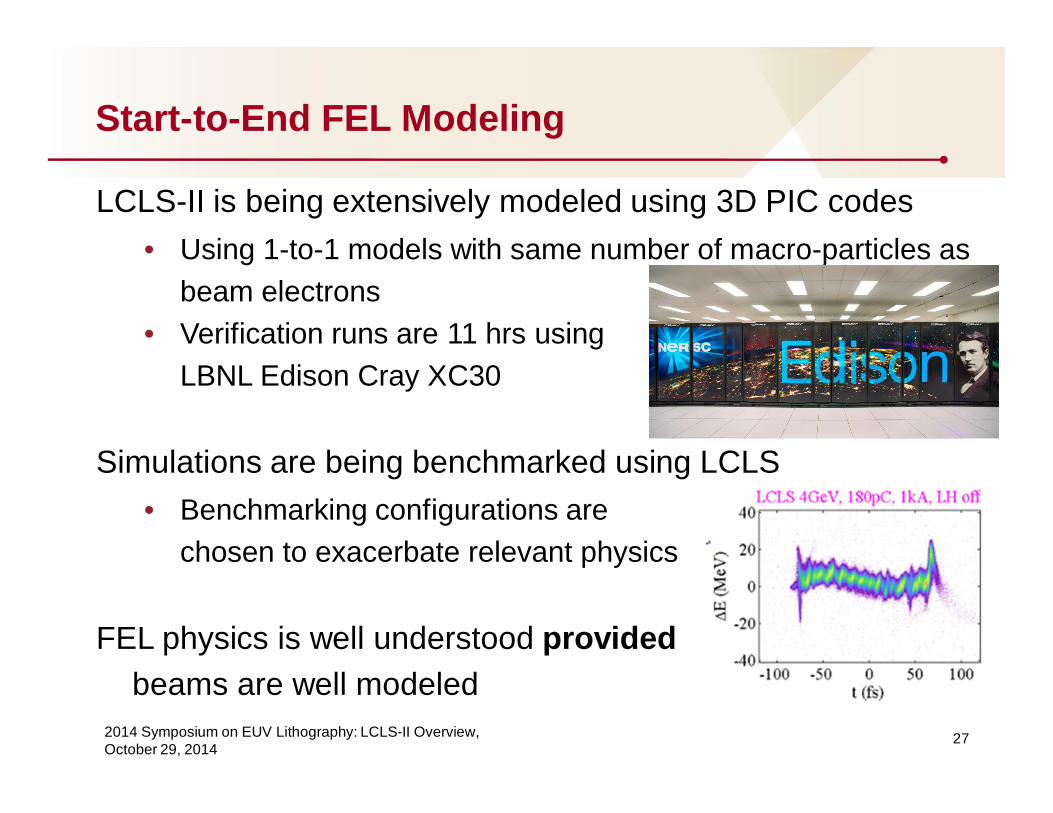
LCLS-II is being extensively modeled using 3D PIC codes• Using 1-to-1 models with same number of macro-particles as
beam electrons• Verification runs are 11 hrs using
LBNL Edison Cray XC30
Simulations are being benchmarked using LCLS• Benchmarking configurations are
chosen to exacerbate relevant physics
FEL physics is well understood providedbeams are well modeled

28
LCLS-II Photon Availability
2014 Symposium on EUV Lithography: LCLS-II Overview,October 29, 2014
LCLS-II is being designed for 95% user availability• Similar to achieved in SR storage rings and LCLS
System Availability DescriptionLasers 99.73 % Injector Laser and Laser Heater
Magnets 99.997 %Bends, Quadrupole, Horizontal and Vertical Correctors, Kickers. Includesmechanical fabrication . It excludes any magnet inside the cryomodule.
PS controllers 99.57 % Power supplies and power supply controllers for magnets.
RF power sources 99.85 % Klystrons, Solid State Amplifiers and high power RF distribution.
SCRF Linac 99.87 %Super Conductive RF cryomodule, Cavities, cavity tuners, RF input coupler,cryomodule vacuum.
Vacuum 99.88 %Vacuum pumps, valves, gauges and controllers. Not to include vacuum componentsinside the cryomodule.
Tuning andDiagnostic 99.16 %
Beam Position Monitor, Wire Scanner and Time spent tuning machine performanceto previously defined X-Ray parameters.
Water system 99.77 % Water pumps, cooling water temperature regulation.
AC power 98.96 % Power distribution system
Cryogenics Plant 98.62 %
Controls 99.62 %Input/output controllers, Machine Protection System, Personnel Protection System,controls backbone, timing, feedback, LLRF.
Photon Controls 99.89 % Front End Enclosure (FEE) diagnostics and controls.
All 95.00 %

29
EUV FEL Consortium
2014 Symposium on EUV Lithography: LCLS-II Overview,October 29, 2014
Group from national labs, universities, and industry studyingoptions for a high power EUV FEL
• Considering a relatively conservative configuration basedon LCLS-II technology
Contact Alex Murokh <[email protected]>

30
Summary
2014 Symposium on EUV Lithography: LCLS-II Overview,October 29, 2014
• FEL’s have become mainstream scientific light sources- Both low gain (oscillators) and high gain (amplifiers)- Physics is well understood from mm’s to Angstrom’s- Advanced technologies are being aggressively developed and
industrialized around the world
• LCLS and LCLS-II are state-of-the-art x-ray FEL’s- LCLS has generated 6 mJ in single pulse- LCLS-II will generate 100’s W from 0.2 to 5 keV
• LCLS-II technologies could be used for EUV source- Single-pass amplifier design is robust with capability for >10kW’s- Alternate configurations possible to improve performance- FEL technology provides natural path to shorter wavelengths

2014 Symposium on EUV Lithography: LCLS-II Overview,October 29, 2014
31
LCLS-II Collaboration