Embed Size (px)
Citation preview

THE KAROO ARRAY TELESCOPE (KAT) &
FPA EFFORT IN SOUTH AFRICA
Dr. Dirk Baker (KAT FPA Sub-system Manager)Prof. Justin Jonas (SKA SA Project Scientist)
Ms. Anita Loots (KAT Project Manager)Mr. David de Haaij (Grintek Antennas)Dr. Riaan Booysen (Grintek Antennas)
FPA WorkshopDwingeloo, The NetherlandsJune 20 – 21,2005

OUTLINE
• THE KAROO ARRAY TELESCOPE (KAT)• ANALYSIS TOOLS AND APPROACH• CONJUGATE FEED MATCHING AND EFFICIENCY• FOCAL FIELDS FOR VARIOUS REFLECTORS• 4 X 3 VIVALDI ARRAY• REQUIREMENTS FOR ANTENNA STRUCTURE• HIGH LEVEL FUTURE PLANS FOR KAT
FPA WorkshopDwingeloo, The NetherlandsJune 20 – 21,2005

SOUTHERN AFRICAN OBSERVATORIES

KAROO?

WHAT WILL KAT BE?
• A technology demonstrator– Developing technologies expected to be
on the critical path of SKA• A working science instrument
– KAT will become part of the SA science infrastructure

KAROO ARRAY TELESCOPE
DBBC
HartRAO (26m dish)
20x RF links (carrier 5GHz, 1 per FPA element) for short haul data transport (200 FPA elements, >10 beams, 250MHz bandwidth, 600 Msps per link, 3.6Gb/second/link)
Central digital signal processor (digital receiver, beam former)
Software for control and monitor
High speed computing
Radio signals
RFI
20 antennas (FPA fitted) with directional control (each 15m diameter) in the frequency range of 0.7GHz to 1.75GHz (extent of the array approx. 200m)
VLBI
JIVEHartRAOcontrol centre
Data-processing &
imaging
Data-capture
Link (11 Gsps, 16 bits per sample?, 176Gb/s?)
Use
r (Sc
ient
ist)
Har
tRA
O, G
aute
ng,
Sout
h A
fric
a
Karo
o, N
orth
ern
Cape
, Sou
th A
frica

KAROO ARRAY TELESCOPE
• Array of 20 x 15 m reflecting concentrators each fed with a focal plane array (10 x 10 element).
• Operating frequency range: 0.7 GHz – 1.75 GHz.• Dual polarization.• Instantaneous bandwidth: 250 MHz each polarization.• Antenna array baselines: 20 m – 2000 m.• Array resolution: 1’ @ 1420 MHz.• >10 independent beams within 10-deg antenna FoV.• Tsys < 50 K (< 0.5 dB LNA noise figure) .• Fully digital with FPGA+HPC back-end.• Multiple Correlators (imaging).• Located in the Karoo, Northern Cape, South Africa.• Four-year development and construction horizon (very
tight).
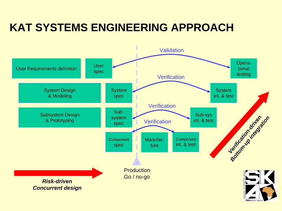
KAT SYSTEMS ENGINEERING APPROACH
User Requirements definition
System Design & Modeling
Subsystem Design & Prototyping
User spec
System spec
Sub-system spec
Componentspec
ProductionGo / no-go
Componentint. & test
Risk-drivenConcurrent design
Verific
ation
-driv
en
Botto
m-up i
nteg
ratio
n
Sub-sys int. & test
System int. & test
Opera-tional
testing
Validation
Manufac-ture
Verification
Verification
Verification
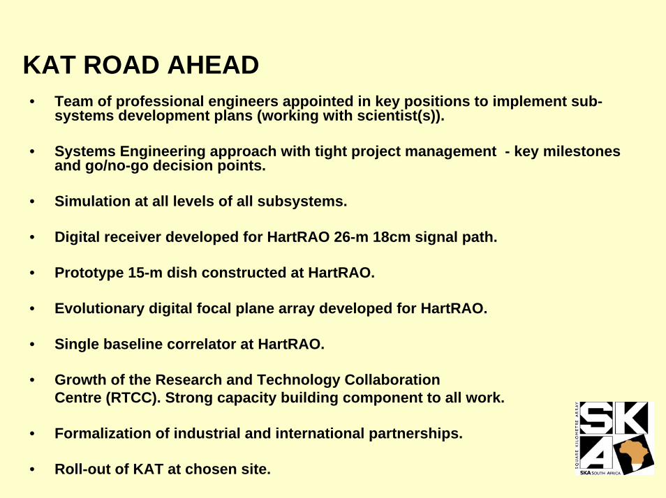
KAT ROAD AHEAD• Team of professional engineers appointed in key positions to implement sub-
systems development plans (working with scientist(s)).
• Systems Engineering approach with tight project management - key milestones and go/no-go decision points.
• Simulation at all levels of all subsystems.
• Digital receiver developed for HartRAO 26-m 18cm signal path.
• Prototype 15-m dish constructed at HartRAO.
• Evolutionary digital focal plane array developed for HartRAO.
• Single baseline correlator at HartRAO.
• Growth of the Research and Technology Collaboration Centre (RTCC). Strong capacity building component to all work.
• Formalization of industrial and international partnerships.
• Roll-out of KAT at chosen site.

HartRAO

KAT FPA and DISH

ANALYSIS TOOLS AND APPROACH
FOCAL FIELDS
FEKO (FEldberechnung bei Körpern mit beliebiger Oberfläche) is a 3D full wave simulator, able to analyze small antennas with MoM and larger structures with either PO or UTD. [email protected] / www.feko.info
SolidWorks is a full 3D mechanical design program used extensively in the industry to do mechanical designs in all fields of engineering. www.solidworks.com
FEMAP is a program normally used to analyze mechanical structures. FEKO uses the meshing of FEMAP to input any structure from SolidWorks into the antenna analysis. www.femap.com

VIVALDIS
IE3D is a full-wave, method-of-moments based electromagnetic simulator solving the current distribution on 3D and multilayer structures of general shape. www.zeland.com
APPROACH
• For dish use FEKO/FEMAP/SOLIDWORKS to analyze focal fields.• Conjugate matching.• In-house software for mutual coupling.• Results presented are a summary of a project which has been
running for only three months.

FEKO BASIC GEOMETRY FOR REFLECTOR, WITH 3D PRESENTATION OF FOCAL REGION FIELD STRENGTH.

CONJUGATE FEED MATCHING AND EFFICIENCY
• Compute focal fields (E, H), hence Poynting vector.• Use Robieux’s theorem for conjugate match of incident focal fields with
the transmit fields of the feed for maximum power transfer.• Integrating the focal fields over an ideal feed of radius a gives the power
extracted from the focal fields. By dividing by the total power incident on the reflector get the efficiency.
• By plotting the computed efficiencies with a normalised radius, the efficiencies for all f/D can be displayed on one graph.
• From this deduce radius of feed for achieving optimum efficiency.• There is a minimum radius for various efficiencies in the 0.4 to 0.6 f/D
range.• Since have choice of f/D, examined f/D = 0.5

MAXIMUM EFFICIENCY OF IDEAL CONJUGATE MATCHED FEED
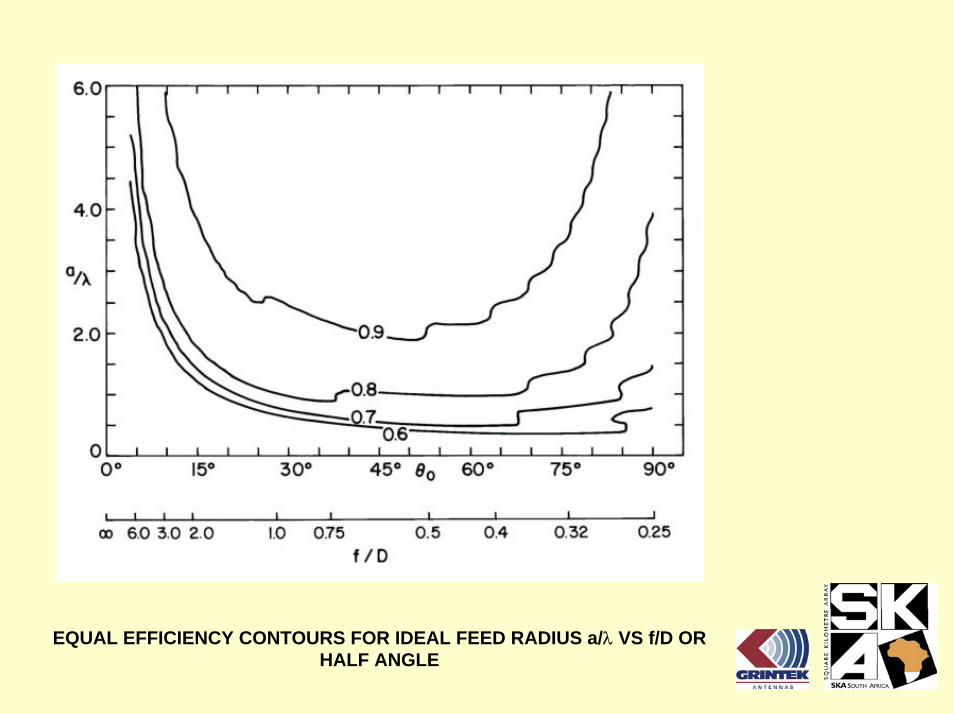
EQUAL EFFICIENCY CONTOURS FOR IDEAL FEED RADIUS a/λ VS f/D OR HALF ANGLE

GEOMETRY FOR 15 m DIAMETER REFLECTORS

SCANNING GEOMETRY FOR REFLECTOR

00 0.50.5 -0.5-0.5
0
0.5
COMPARISON IN FOCAL POINT NEAR FIELD STRENGTH ON A 15m DISH;F/D = 0.33 (LEFT) AND F/D = 0.5 (RIGHT)

00 0.50.5 -0.5-0.5
0
0.5
COMPARISON IN X-pol FOCAL POINT NEAR FIELD ON A 15m DISH;F/D = 0.33 (LEFT) AND F/D = 0.5 (RIGHT)

-0.1-0.1 0.90.9
0
0.5
COMPARISON IN FOCAL POINT NEAR FIELD; 4° OFF-AXIS SCANNING ON A 15m DISH; F/D = 0.33 (LEFT) AND F/D = 0.5 (RIGHT)

-0.1-0.1 0.90.9
0
0.5
COMPARISON IN X-pol FOCAL POINT NEAR FIELD; 4° OFF-AXIS SCANNING ON A 15m DISH; F/D = 0.33 (LEFT) AND F/D = 0.5 (RIGHT)

00 11 -1-1
0
1
COMPARISON IN FOCAL POINT NEAR FIELD; 3° AT 45° TO PRINCIPAL PLANE ON A 15m DISH; F/D = 0.33 (LEFT) AND F/D = 0.5 (RIGHT)

00 11 -1-1
0
1
COMPARISON IN X-pol FOCAL POINT NEAR FIELD; 3° OFF-AXIS SCANNING ON A 15m DISH; F/D = 0.33 (LEFT) AND F/D = 0.5 (RIGHT)

TOTAL E-FIELD STRENGTH AT -3, 0° AND 3° INCOMING WAVE FOR AN OFFSET REFLECTOR WITH FOCAL DISTANCE 7.5m (LEFT) AND 9m (RIGHT).
FPA
(31,
3°)
FPA (3
7°)
00 11 -1-1
0
1

00 0.50.5 -0.5-0.5
0
0.5
Co-pol E-FIELD STRENGTH AT BORESIGHT INCOMING WAVE FOR AN OFFSET REFLECTOR WITH FOCAL DISTANCE 7.5m (LEFT) AND 9m (RIGHT).

00 0.50.5 -0.5-0.5
0
0.5
X-pol E-FIELD STRENGTH AT BORESIGHT INCOMING WAVE FOR AN OFFSET REFLECTOR WITH FOCAL DISTANCE 7.5m (LEFT) AND 9m (RIGHT).

00 11 -1-1
0
1
Co-pol E-FIELD STRENGTH AT -3° ON-AXIS INCOMING WAVE FOR AN OFFSET REFLECTOR WITH FOCAL DISTANCE 7.5m (LEFT) AND 9m (RIGHT).
00 11 -1-1
0
1
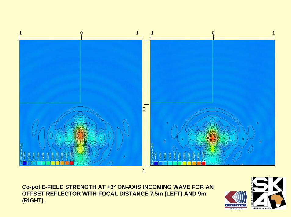
Co-pol E-FIELD STRENGTH AT +3° ON-AXIS INCOMING WAVE FOR AN OFFSET REFLECTOR WITH FOCAL DISTANCE 7.5m (LEFT) AND 9m (RIGHT).

00 11 -1-1
0
1
Co-pol E-FIELD STRENGTH AT +3° OFF-AXIS INCOMING WAVE FOR AN OFFSET REFLECTOR WITH FOCAL DISTANCE 7.5m (LEFT) AND 9m (RIGHT).

FIRST ITERATION 4x3 VIVALDI ARRAY INVESTIGATED AT GRINTEK ANTENNAS

700MHz RADIATION PATTERN OF VIVALDI ANTENNA IN CENTER OF 4x3 ARRAYELEMENT 5
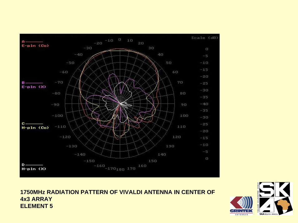
1750MHz RADIATION PATTERN OF VIVALDI ANTENNA IN CENTER OF 4x3 ARRAYELEMENT 5

700MHz RADIATION PATTERN OF VIVALDI ANTENNA ON EDGE OF 4x3 ARRAYELEMENT 11

1750MHz RADIATION PATTERN OF VIVALDI ANTENNA ON EDGE OF 4x3 ARRAYELEMENT 11

COUPLING BETWEEN ELEMENTS IN 4 X 3 VIVALDI ARRAY

REQUIREMENTS FOR ANTENNA STRUCTURE FOR KAT
• Must be equipped with lightning protection.• Surface accuracy: 2 to 3 mm rms (random surface error factor
= 0.979 to 0.953).• Pointing accuracy 0.01. (set by dB variation at 3 dB crossover
between adjacent beams).
Operation Gravity[El-range]
Temp Rain Ice & Snow Wind inclgusts
[° El] [° C] [mm/h] [kg/m²] [km/h]
Normal -5 to 90 -5 to 40 None None 0 – 20
Drive to stow
N/A N/A 10 25 36
Survival in any position
N/A -20 to 50 25 25 100
Survival in stow position
N/A -20 to 50 50 25 200
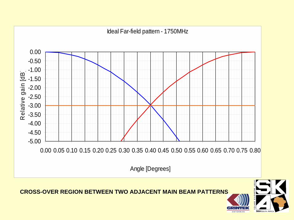
CROSS-OVER REGION BETWEEN TWO ADJACENT MAIN BEAM PATTERNS
Ideal Far-field pattern - 1750MHz
-5.00-4.50-4.00-3.50-3.00-2.50-2.00-1.50-1.00-0.500.00
0.00 0.05 0.10 0.15 0.20 0.25 0.30 0.35 0.40 0.45 0.50 0.55 0.60 0.65 0.70 0.75 0.80
Angle [Degrees]
Rel
ativ
e ga
in [d
B]

Elevation Azimuth
Zenith From true North
Range of Motion -5 to 90 +-230
Slew speed 2 deg/s 2 deg/s
Slew acceleration 2 deg/s² 2 deg/s²
Duty cycle (slewing / tracking
20 min
DRIVE DATA

HIGH LEVEL FUTURE PLANS FOR KAT• R&D, Trade-offs and iterations until end of 2006 (technology
freeze)
• Continue investigation of electrical performance of prime focus,offset, folded optics, etc antennas.
• Investigate alternate elements to Vivaldis for FPAs.
• Manufacture 10 x 10 x 2 FPA and evaluate (include mutual coupling).
• Dish mechanical design and investigation of low cost manufacture including pedestal and control.
• Digital receiver prototype.
• Digital beamformer prototype.
• Correlator prototype.