Embed Size (px)
Citation preview
JOURNAL OF MATERIALS AND ENGINEERING STRUCTURES 6 (2019) 105–118 105
Research Paper
The Influence of Deformability of Horizontal Diaphragms in the Distribution of Seismic Loads to Bracing Elements in Rectangular Buildings
Sadek Bahar a,*, Abdelkader Benanane a, Abdeldjelil DJ Belarbi b a LMPC, Department of Civil Engineering and Architecture, Faculty of Sciences and Technology, University Abdelhamid Ibn Badis, Mostaganem 27000, Algeria b Department of Civil and Environmental Engineering, University of Houston, Houston TX 77204, USA
A R T I C L E I N F O
Article history :
Received : 25 May 2018
Received : 28 December 2018
Accepted : 29 December 2018
Keywords:
Earthquake
Rigid Diaphragm
Flexible Diaphragm
Shear forces
Shear wall
A B S T R A C T
The operations of a floor, as a significant structural element, have an influence on the stability of the structure when it acts as a horizontal diaphragm. In this study, the in-plane deformability of rectangular floors of single story buildings is examined under the effects of horizontal seismic actions. Therefore, the effects of parameters influencing the behavior of the floor such as size opening and their location, position of shear walls, span-to-depth ratio, and materials constituting the floor were studied. Results suggest that a diaphragm will behave in a flexible manner whether it is classified as rigid or flexible. However, a small opening in the floor can change the behavior of a diaphragm assumed rigid and make it behave like a flexible diaphragm. Additionally, flexible diaphragms can distribute horizontal seismic shear forces to vertical resisting elements due to the relative rigidity of the shear wall. These results are in contradiction with seismic codes such as ASCE/SEI 7-10, FEMA 356, and Eurocode 8, further the size of opening that make flexible diaphragm behave like rigid diaphragm was suggested by formula. For the building with a shear wall, the classification of the diaphragm in seismic codes such ASCE is not accurate enough and they need to reform with taking into consideration the location of the opening in the floor.
1 Introduction
When structures are subjected to earthquake loads, their seismic response depends on the characteristics of the vertical lateral force resisting systems such as bracing elements and structural frames as well as the horizontal lateral force resisting elements [4]. The function of floors in a building is very important in the overall seismic behavior of the structure. They act as horizontal diaphragms, which collect the inertial forces, transmit them to the vertical structural elements, and make these
* Corresponding author. Tel.: +213 775196880. E-mail address: [email protected] e-ISSN: 2170-127X,
brought to you by COREView metadata, citation and similar papers at core.ac.uk
provided by Université Mouloud Mammeri de Tizi Ouzou (UMMTO): Research Review of Sciences and...
106 JOURNAL OF MATERIALS AND ENGINEERING STRUCTURES 6 (2019) 105–118
elements interdependent to resist horizontal seismic action. The ability for a structure to resist this dynamic loading depends largely on the relative rigidity of the connection between vertical and horizontal elements. When analyzing structures, diaphragms are classified as rigid, flexible, or semi-rigid, based on the definition of relative rigidity. If a diaphragm is considered rigid, it can distribute horizontal forces to vertical elements in proportion to its relative rigidity. In this case, the deformation of the diaphragm will be insignificant compared to the deformation of the vertical elements [5]. Rigid diaphragm deformation characteristics are defined by a master node that has three degrees of freedom: two lateral displacements in the plane of the diaphragm and one rotation around the central axis. All other nodes are called slave nodes that contain three degrees of freedom: two in-plane rotations and one out-of-plane translation [6-7]. This assumption was conceived half a century ago and has serious limitations for buildings with considerable in-plane diaphragm deformation [8-9].
In a flexible diaphragm, the distribution of horizontal forces to vertical elements is independent on their relative rigidity and the deformation of the diaphragm will be substantially larger compared to that of the vertical elements [5]. A flexible diaphragm consists of a series of simple beams which distribute lateral loads to vertical elements. In essence, seismic shear forces are distributed to the vertical elements of a seismic force resisting system using tributary area rules [1]. Flexible diaphragm nodes contain six degrees of freedom which include the three translations and three rotations [10].
There has been limited research performed on the flexibility of diaphragms and their influence on the lateral distribution forces to shear walls and columns. In reality, no diaphragm is perfectly rigid or perfectly flexible; however, diaphragms can be considered as rigid or flexible in order to simplify the analysis. In the case where the deformations of the diaphragm and vertical elements are similar, the diaphragm is considered to be semi-rigid. The distribution of lateral loads in a semi-rigid diaphragm can be considered as a continuous beam supported on elastic supports [5]. The linear response of a structure with flexible floors under seismic actions in terms of displacement is largely unexplored. Some seismic standards (European as Eurocode [3] and American as ASCE/SEI 7-10 [1], and FEMA 356 [2] recommend the use of specific methods based on the principle of finite element analysis which may provide a good indication on the seismic behavior of the structure to overcome these disadvantages.
To reduce the risk of possible catastrophes during earthquakes, the seismic codes recommend the use of reinforced concrete (RC) shear walls as resisting systems. In practice, a certain ambiguity covers the in-plane deformation of the floors as the diversity of criteria used in the international seismic codes. The range of the limits characterizing the rigidity of a diaphragm is clear when comparing the different international seismic codes. The criteria of proportions of openings in a floor and the shape of plan diaphragm can show enormous differences. A case study is necessary to comprehend this ambiguity about the criteria used by the international seismic codes.
This study represents an analytical comparison between rigid and flexible diaphragm assumption. The distribution of shear force in vertical resisting elements on the rigid and flexible diaphragm will be investigated with parameters (1); size of the opening in the floor, (2); position of opening in the middle and in the corner of floors, (3); the position of interior walls, (4); the ratio between length and width, and (5); the type of materials constituting the floors. Further, a comparison of distribution of shear force in the wall between finite element method and calculation methods (tributary area method, stiffness method, and inertia method) are investigated. In addition the low rise buildings analyzed in this study have one storey with six different sizes of opening in the floor, three different positions of the interior wall, and three ratios of length and width, the width is fixed at 10.5 meters while the length is 21, 24.5, and 33 meters. Moreover the floor analyzed with two types of materials; concrete slab floor, and block joist floor.
2 Previous Research on Diaphragms
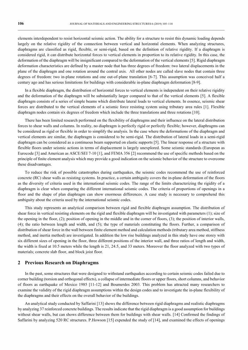
In the past, some structures that were designed to withstand earthquakes according to certain seismic codes failed due to corner building (torsion and orthogonal effects), a collapse of intermediate floors or upper floors, short columns, and behavior of floors as earthquake of Mexico 1985 [11-12] and Boumerdes 2003. This problem has attracted many researchers to examine the validity of the rigid diaphragm assumptions within the design codes and to investigate the in-plane flexibility of the diaphragms and their effects on the overall behavior of the buildings.
An analytical study conducted by Saffarini [13] shows the difference between rigid diaphragms and realistic diaphragms by analyzing 37 reinforced concrete buildings. The results indicate that the rigid diaphragm is a good assumption for buildings without shear walls, but can shows difference between them for buildings with shear walls. [14] Confirmed the findings of Saffarini by analyzing 520 RC structures. P.Howson [15] expended the study of [14], and examined the effects of openings
JOURNAL OF MATERIALS AND ENGINEERING STRUCTURES 6 (2019) 105–118 107
in the middle of the slab by analyzing 384 reinforced concrete buildings. The position of openings, type of floor, and presence of interior walls and their position were not indicated in the study. Studies by Kim [16] and Jain [17] focused on the development of a simple analytical method for dynamic analysis for low-rise buildings with flexible diaphragms supported by end walls. They found that the dynamic response of the structure was dominated by floor flexibility. The paper [18] investigated the effects of diaphragm openings and their flexibility in RC buildings with shear walls and having plan aspect ratios of 4:1 for three and five story structures. The results indicated that presence of openings in a rigid diaphragm caused erroneous deformations and non-conservative results compared to the case of slabs without openings.
The paper [19] evaluated the impact of in-plane diaphragm deformation on the structural response of three and five story RC rectangular buildings with rigid diaphragm assumptions. He found that the use of a flexible diaphragm model had the largest impact on the three story structure with an aspect ratio of 3:1. These results demonstrated that the various analysis procedures in FEMA 273 [20] gave different adequate assessments for the case of building. The paper [4] studied nonlinear responses of braced steel buildings with flexible diaphragms, concrete block joist floors, under both static and dynamic lateral loads. It was demonstrated that the span ratio is an important parameter in the flexibility of floor diaphragms, and if the ratio exceeds three, the variation of results between the two assumptions of flexible and rigid diaphragms may not be ignored.
A study conducted by Vinod [21] focused on quantifying the seismic response of structures with flexible diaphragms. The results showed that displacements of single story elastically responding structures tend to be most significantly affected by diaphragm flexibility. The paper [22] studied the in-plane structural behavior of reinforced concrete floor slabs by investigating the inelastic behavior of RC floor diaphragms with openings by using the finite element approach. The study has been conducted to investigate the effects of varying opening sizes. The results indicated that presence of openings changed the in-plane behavior of RC slabs compared with the slabs without openings and ignoring the opening effects might lead to erroneous results. Also, the author concluded that the larger the opening size, the less significant the effect of out-of-plane loading on in-plane capacity reduction of the slabs, and the smaller the opening size, the less change was observed on in-plane behavior of the slabs. The paper [23] studied the effects of diaphragm flexibility on the seismic response of single story buildings that have flexible diaphragms. The results showed that the nonlinearity in the lateral load resisting system causes a considerable increase in the ductility demands imposed on the lateral load resisting system. In determining the stiffness of the diaphragm, the shear deformation plays an important role. Shear deformation may be significantly larger than the flexural deformation in certain types of diaphragms. Therefore, the shear deformation must be taken into account in an analysis of the diaphragm.
3 Structural Modeling
216 rectangular reinforced concrete structures of single story with shear walls were selected for spectrum and static nonlinear analysis in this study. All shear walls had the same length, height, and thickness (length of 10.5m, height of 3.06m, and thickness of 20cm) For all buildings the columns size was 35 × 35 cm, the size of the beams was 25 × 35 cm. The structural finite element software, ETABS [24], was used for the analytical modeling of the structures considered. The floors were assumed as either rigid or flexible diaphragms. The seismic loads subjected to the structures are based response seismic spectrum analysis, according to the Algerian seismic code [25], the seismic load is applied parallel to the short side of the building. In the Mediterranean basin, Algeria is considered as one of the most seismically active areas.
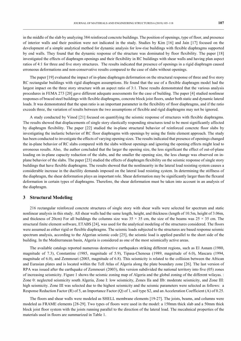
The available catalogs reported numerous destructive earthquakes striking different regions, such as El Asnam (1980, magnitude of 7.3), Constantine (1985, magnitude of 5.9), Tipasa-Chenoua (1989, magnitude of 6.0), Mascara (1994, magnitude of 6.0), and Zemmouri (2003, magnitude of 6.8). This seismicity is related to the collision between the African and Eurasian plates and is located within the Tell Atlas of Algeria along the plate boundary zone [26]. The last version of RPA was issued after the earthquake of Zemmouri (2003), this version subdivided the national territory into five (05) zones of increasing seismicity. Figure 1 shows the seismic zoning map of Algeria and the global zoning of the different wilayas. : Zone 0: neglected seismicity south Algeria, Zone I: low seismicity, Zones IIa and IIb: moderate seismicity, and Zone III: high seismicity. Zone III was selected due to the highest seismicity and the seismic parameters were selected as follows: a Response Reduction Factor (R) of 5, an Importance Factor (Q) of 1, soil type S2, and an Acceleration Coefficient (A) of 0.25.
The floors and shear walls were modeled as SHELL membrane elements [19-27]. The joists, beams, and columns were modeled as FRAME elements [28-29]. Two types of floors were used in the model: a 150mm thick slab and a 50mm thick block joist floor system with the joists running parallel to the direction of the lateral load. The mecahnical properties of the materials used in floors are summarized in Table 1.
108 JOURNAL OF MATERIALS AND ENGINEERING STRUCTURES 6 (2019) 105–118
Figure 1- Seismic Macrozoning Map of North Algeria (RPA , 2003)
Table 1- Mechanical Material Properties.
Mechanical Material Properties of Concrete
Mechanical Material Properties of Steel
Modulus of Elasticity, E (kN/m2 ) 32. 164. 200 203. 890. 200
Poisson Ratio 0.2 0.3
Compressive and Yield Strength (MPa) 25 400
The parameters studied were:
1. the position of the interior shear walls,
2. the span-to-depth ratios,
3. the size of the opening in the floor,
4. the position of opening in the floor, and
5. the type of materials constituting the floor.
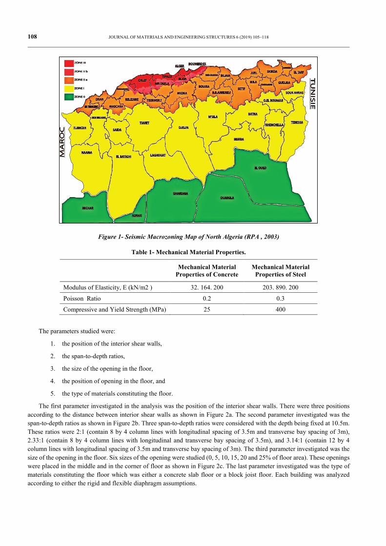
The first parameter investigated in the analysis was the position of the interior shear walls. There were three positions according to the distance between interior shear walls as shown in Figure 2a. The second parameter investigated was the span-to-depth ratios as shown in Figure 2b. Three span-to-depth ratios were considered with the depth being fixed at 10.5m. These ratios were 2:1 (contain 8 by 4 column lines with longitudinal spacing of 3.5m and transverse bay spacing of 3m), 2.33:1 (contain 8 by 4 column lines with longitudinal and transverse bay spacing of 3.5m), and 3.14:1 (contain 12 by 4 column lines with longitudinal spacing of 3.5m and transverse bay spacing of 3m). The third parameter investigated was the size of the opening in the floor. Six sizes of the opening were studied (0, 5, 10, 15, 20 and 25% of floor area). These openings were placed in the middle and in the corner of floor as shown in Figure 2c. The last parameter investigated was the type of materials constituting the floor which was either a concrete slab floor or a block joist floor. Each building was analyzed according to either the rigid and flexible diaphragm assumptions.
JOURNAL OF MATERIALS AND ENGINEERING STRUCTURES 6 (2019) 105–118 109
-a- Different Position Walls -b- Different Span-to-Depth Ratios
-c - Different Position of Opening
Figure 2- Building Parameters used in Analysis.
4 Code Provisions
The distribution of shear load and torsional moment in the vertical resisting elements depends on the flexibility of the diaphragm. Therefore, the behavior of the structure is dependent on the behavior of the diaphragm. Due to this important role, seismic codes indicate the classification of diaphragms, but there is a difference in the classification of diaphragms between all seismic codes. Some of these codes classify the diaphragm with certain qualitative criteria related to its shape, while others classify the diaphragm with quantitative criteria relating to its in-plane deformation. Table 2 summarizes the different classifications of diaphragms in international seismic codes. Seismic codes were chosen on the basis of different countries in the world and the most advanced in seismicity which is: Minimum Design Loads for Buildings and Other
Position 3 7 @ 3m
3 @
3.5
m
Position 2
3@ 3
.5m
7 @ 3.5m
Position 1 11 @ 3m
3@ 3
.5m
110 JOURNAL OF MATERIALS AND ENGINEERING STRUCTURES 6 (2019) 105–118
Structures ASCE/SEI 7-10 [1], California Code of Regulations [30], International Building Code [31], New Zealand Standard [32], Federal Emergency Management Agency [2], Eurocode 8 [3], and Algerian Earthquake Resistant Regulations [25].
Table 2- Different Classifications of Diaphragms in International Seismic Codes
Displacement Δ story Opening area Ratio L/l
RPA X ≤ 15% floor area ≤ 04
EC 08 ≤ 10% displacement resulting from the assumption of rigid diaphragm X ≤ 04
ASCE 7 CBC IBC
Rigid; when displacement story ≤ 2 Δ average story drift ≤ 50% total floor area ≤ 03
FEMA
Rigid; when displacement story ≤ 0.5 Δ average story drift Flexible when displacement story ≥ 2 Δ average story drift
≤ 50% total floor area ≤ 03
New Zealand Standard NZS
Rigid; when displacement story ≤ 2 Δ average story drift
≤ 50% total floor area X/b ≤ 0.6 Y/D ≤ 0.5; b is span length of diaphragm. D is Depth of diaphragm. X,Y are the cumulative dimensions
≤03 good ≤04 fail ≥ 04 pool
5 Results of the Parameters Studies
Extensive research and comprehensive study have been conducted to determine how shear deformation plays an important role in the diaphragm design. Shear deformation may be significantly larger than the flexural deformation in certain types of diaphragms [23]. In this section, the difference between flexible and rigid diaphragm assumptions for the distribution of shear force in vertical resisting elements was determined by using Eq. (1) below. The equation was also used to investigate the influence of parametric study that was not included in the literature for the distribution of shear force.
n 4 n 4
rij fij fiji 1 j 1 i 1 j 1
Error V % 100 V V / V= = = =
= × −∑∑ ∑∑ (1)
Where n is the mean total number of columns or walls in the building, j is the shear force of two columns or wall ends for the x-axis and y-axis, Vrij is the shear force of column or wall i using the rigid diaphragm assumption, and Vfij is the shear force of column or wall i using the flexible diaphragm assumption.
The results obtained by using the equation above are presented in Figure 3 below. The figure shows the results of 216 buildings analyzed under either a flexible diaphragm or rigid assumption. Half of the 216 buildings included concrete slab floors and the other half included block joist floors. Each point in the figure represents the error of Eq. (1) compared from a rigid floor and a flexible floor building.
Buildings with dimensions of 10.5 m by 21 m, 10.5 m by 24.5 m, and 10.5 m by 33 m are presented as 2, 2.33 and 3.14, respectively. The position of the opening in a floor is referenced as M or C for middle or corner respectively. P1, P2, and P3 represent the index of position 1, position 2, and position 3, respectively. The type of floor is referenced as CS or BJ for concrete slab floor or block joist floor, respectively.
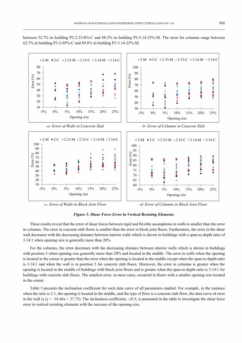
Figure 3a shows the shear force error of walls in concrete slab floors. The smallest error is 13.3% in the building when the position of the wall is position 3, span-to-depth ratio is 2:1, with 5% of the opening located in the corner (P3-2-05%-C). The maximum error is 68.4% in the building when the position of the wall is P1, span-to-depth ratio is 2.33:1, with 20% of the opening located in the corner (P1-2.33-20%-C). Figure 3b shows the shear force error of columns in concrete slab floors. This range in error is 31.5% to 81.0% for buildings P3-2-05%-C and P1-2.33-25%-C, respectively. Figure 3c and Figure 3d shows the shear force error of walls and columns for block joist floors, respectively. For the shear walls, the error range is
JOURNAL OF MATERIALS AND ENGINEERING STRUCTURES 6 (2019) 105–118 111
between 32.7% in building P2-2.33-0%-C and 88.5% in building P3-3.14-25%-M. The error for columns range between 62.7% in building P3-2-05%-C and 89.8% in building P3-3.14-25%-M.
-a- Error of Walls in Concrete Slab -b- Error of Columns in Concrete Slab
-c- Error of Walls in Block Joist Floor -d- Error of Columns in Block Joist Floor
Figure 3- Shear Force Error in Vertical Resisting Elements.
These results reveal that the error of shear forces between rigid and flexible assumptions in walls is smaller than the error in columns. The error in concrete slab floors is smaller than the error in block joist floors. Furthermore, the error in the shear wall decreases with the decreasing distance between interior walls which is shown in buildings with a span-to-depth ratio of 3.14:1 when opening size is generally more than 20%.
For the columns, the error decreases with the decreasing distance between interior walls which is shown in buildings with position 3 when opening size generally more than 20% and located in the middle. The error in walls when the opening is located in the corner is greater than the error when the opening is located in the middle except when the span-to-depth ratio is 3.14:1 and when the wall is in position 3 for concrete slab floors. Moreover, the error in columns is greater when the opening is located in the middle of buildings with block joist floors and is greater when the span-to-depth ratio is 3.14:1 for buildings with concrete slab floors. The smallest error, in most cases, occurred in floors with a smaller opening size located in the corner.
Table 3 presents the inclination coefficient for each data curve of all parameters studied. For example, in the instance when the ratio is 2:1, the opening is located in the middle, and the type of floor is a concrete slab floor, the data curve of error in the wall is (y = -18.46x + 37.75). The inclination coefficient, -18.5, is presented in the table to investigate the shear force error in vertical resisting elements with the increase of the opening size.
1020304050607080
-5% 0% 5% 10% 15% 20% 25%
Erro
r (%
)
Opening size
2-M 2-C 2.33-M 2.33-C 3.14-M 3.14-C
30405060708090
100
-5% 0% 5% 10% 15% 20% 25%
Erro
r (%
)
Opening size
2-M 2-C 2.33-M 2.33-C 3.14-M 3.14-C
102030405060708090
100
-5% 0% 5% 10% 15% 20% 25%
Erro
r (%
)
Opening zise
2-M 2-C 2.33-M 2.33-C 3.14-M 3.14-C
6065707580859095
100
-5% 0% 5% 10% 15% 20% 25%
Erro
r (%
)
Opening zise
2-M 2-C 2.33-M 2.33-C 3.14-M 3.14-C
112 JOURNAL OF MATERIALS AND ENGINEERING STRUCTURES 6 (2019) 105–118
Table 3- Inclination Coefficient of the Error Data Curve.
The result shows that with the increase of span-to-depth ratio, the influence of opening size increases, especially when
span-to-depth ratio is equal to 3.14:1. The Increase of the size of the opening has a greater impact on the error of the walls. However, with the increase of the opening size, the error in walls decreases for buildings of a span-to-depth ratio of 2:1 when the opening is located in the middle. Also, in position 1 and 2 of interior walls, the error decreases with the increase of opening size when located in the middle.
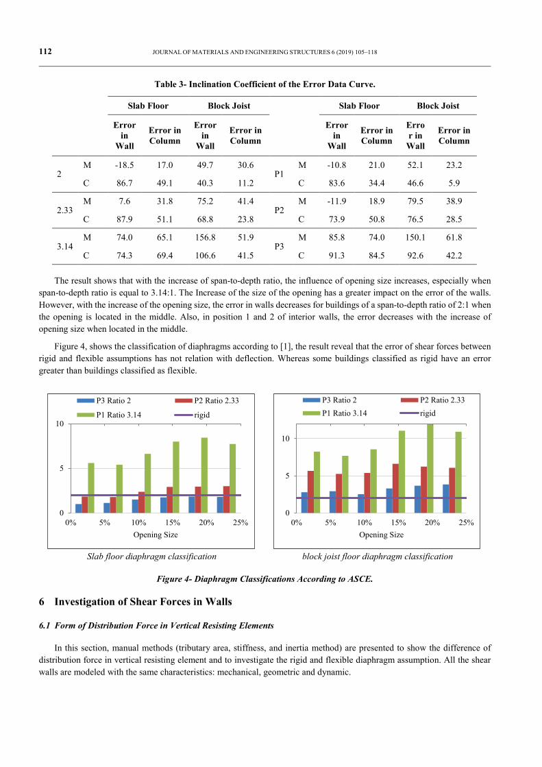
Figure 4, shows the classification of diaphragms according to [1], the result reveal that the error of shear forces between rigid and flexible assumptions has not relation with deflection. Whereas some buildings classified as rigid have an error greater than buildings classified as flexible.
Slab floor diaphragm classification block joist floor diaphragm classification
Figure 4- Diaphragm Classifications According to ASCE.
6 Investigation of Shear Forces in Walls
6.1 Form of Distribution Force in Vertical Resisting Elements
In this section, manual methods (tributary area, stiffness, and inertia method) are presented to show the difference of distribution force in vertical resisting element and to investigate the rigid and flexible diaphragm assumption. All the shear walls are modeled with the same characteristics: mechanical, geometric and dynamic.
0% 5% 10% 15% 20% 25%0
5
10
Opening Size
P3 Ratio 2 P2 Ratio 2.33
P1 Ratio 3.14 rigid
0% 5% 10% 15% 20% 25%0
5
10
Opening Size
P3 Ratio 2 P2 Ratio 2.33P1 Ratio 3.14 rigid
Slab Floor Block Joist
Slab Floor Block Joist
Error in
Wall
Error in Column
Error in
Wall
Error in Column
Error in
Wall
Error in Column
Error in
Wall
Error in Column
2 M -18.5 17.0 49.7 30.6
P1 M -10.8 21.0 52.1 23.2
C 86.7 49.1 40.3 11.2 C 83.6 34.4 46.6 5.9
2.33 M 7.6 31.8 75.2 41.4
P2 M -11.9 18.9 79.5 38.9
C 87.9 51.1 68.8 23.8 C 73.9 50.8 76.5 28.5
3.14 M 74.0 65.1 156.8 51.9
P3 M 85.8 74.0 150.1 61.8
C 74.3 69.4 106.6 41.5 C 91.3 84.5 92.6 42.2
JOURNAL OF MATERIALS AND ENGINEERING STRUCTURES 6 (2019) 105–118 113
6.1.1 Inertia Method (Rigidity of the Elements):
According to [33], this method is the most accurate method for calculating the horizontal force applied in vertical elements. The shear forces in the vertical resisting elements according to this method are decomposed as follows in Eq. (2):
2 i i iwall i translation torsion wall i s s
i i i
I e xV F R V F F
I I x= + => = +
∑ ∑ (2)
Where Vwall i = the force applied in the wall i, Ftranslation = the force provided by the translation; and Rtorsion = the force provided by the torsion. Fs = storey shear force; Ii = the inertia moment; ∑ Ii = the total inertia moment in the storey; ei= the eccentricity; and xi = the distance between wall I and the center of stiffness.
The first part of the equation depends only on the rigidity of the wall and the second part is related to the overall configuration of the story. The effect of torsion was eliminated for the buildings in this study and all walls are parallel to the seismic force so the final force applied in the wall is:
iwall i translation wall i s
i
IV F V F
I= ⇒ =
∑ (3)
6.1.2 Stiffness Method:
In this approach, notion of rigidity of a vertical resisting element is directly related to the displacement as presented in Eq. (4). The lateral displacement of a wall is obtained from the principle of virtual forces in addition to flexural deformation and shear deformation as given in Eq. (5).
wall i i iV K= ∆ (4)
3
3i w i w
total flexural sheari
F h F hEI GA
∆ = ∆ + ∆ = + ∝ , P = 1 (5)
Where α = 1.2 and G = 0.4E which is a good approximation for masonry and concrete [34].The flexural deformation for a wall with fixed–fixed conditions is four times smaller than the flexural deformation for a cantilever. Therefore Eq. (5) becomes:
6.1.2.1 Cantilever wall, rotated at top as in flexible diaphragm:
2
/ 4 3canh hK E tL L
= +
(6)
6.1.2.2 Fixed wall, fixed against rotation at top as in rigid diaphragm:
2
/ 3fixedh hK E tL L
= +
(7)
Where Ki= stiffness of wall i; Δi = displacement of wall I; A = cross-sectional area; E = Young’s modulus; G = shear modulus; hw = wall height; L = wall length; and t = thickness of wall.
6.1.3 Tributary Area Method:
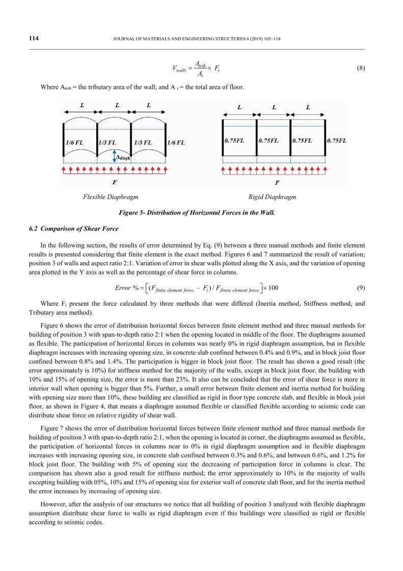
This method is initiated by computing the forces on the wall due to the horizontal seismic force applied on the floor. To calculate shear forces in the wall by this method, it needs to divide the surrounded area of wall by the total area of the floor and multiply the percentage of the horizontal seismic force applied on the slab as presented in Eq. (8). Figure 5 presents differences in distribution of horizontal forces to the wall in rigid and flexible diaphragms when shear walls have the same mechanical and geometrical characteristic.
114 JOURNAL OF MATERIALS AND ENGINEERING STRUCTURES 6 (2019) 105–118
tribwalli i
t
AV F
A= × (8)
Where Atrib = the tributary area of the wall; and A t = the total area of floor.
Flexible Diaphragm Rigid Diaphragm
Figure 5- Distribution of Horizontal Forces in the Wall.
6.2 Comparison of Shear Force
In the following section, the results of error determined by Eq. (9) between a three manual methods and finite element results is presented considering that finite element is the exact method. Figures 6 and 7 summarized the result of variation; position 3 of walls and aspect ratio 2:1. Variation of error in shear walls plotted along the X axis, and the variation of opening area plotted in the Y axis as well as the percentage of shear force in columns.
% ( – ) / 1 00 finite element force i finete element forceError F F F = × (9)
Where Fi present the force calculated by three methods that were differed (Inertia method, Stiffness method, and Tributary area method).
Figure 6 shows the error of distribution horizontal forces between finite element method and three manual methods for building of position 3 with span-to-depth ratio 2:1 when the opening located in middle of the floor. The diaphragms assumed as flexible. The participation of horizontal forces in columns was nearly 0% in rigid diaphragm assumption, but in flexible diaphragm increases with increasing opening size, in concrete slab confined between 0.4% and 0.9%, and in block joist floor confined between 0.8% and 1.4%. The participation is bigger in block joist floor. The result has shown a good result (the error approximately is 10%) for stiffness method for the majority of the walls, except in block joist floor, the building with 10% and 15% of opening size, the error is more than 23%. It also can be concluded that the error of shear force is more in interior wall when opening is bigger than 5%. Further, a small error between finite element and inertia method for building with opening size more than 10%, these building are classified as rigid in floor type concrete slab, and flexible in block joist floor, as shown in Figure 4, that means a diaphragm assumed flexible or classified flexible according to seismic code can distribute shear force on relative rigidity of shear wall.
Figure 7 shows the error of distribution horizontal forces between finite element method and three manual methods for building of position 3 with span-to-depth ratio 2:1, when the opening is located in corner, the diaphragms assumed as flexible, the participation of horizontal forces in columns near to 0% in rigid diaphragm assumption and in flexible diaphragm increases with increasing opening size, in concrete slab confined between 0.3% and 0.6%, and between 0.6%, and 1.2% for block joist floor. The building with 5% of opening size the decreasing of participation force in columns is clear. The comparison has shown also a good result for stiffness method; the error approximately to 10% in the majority of walls excepting building with 05%, 10% and 15% of opening size for exterior wall of concrete slab floor, and for the inertia method the error increases by increasing of opening size.
However, after the analysis of our structures we notice that all building of position 3 analyzed with flexible diaphragm assumption distribute shear force to walls as rigid diaphragm even if this buildings were classified as rigid or flexible according to seismic codes.

JOURNAL OF MATERIALS AND ENGINEERING STRUCTURES 6 (2019) 105–118 115
Inertia method Stiffness method
Area method participation force in columns
Figure 6- Error of distribution horizontal forces in shear wall for position 3 ratio 2 flexible diaphragms (opening located in middle)
Inertia method Stiffness method
Area method participation force in columns
Figure 7- Error of distribution horizontal forces in shear wall for position 3 ratio 2:1 flexible diaphragms (opening located in corner)
-40 -30 -20 -10 0 10 20 30
0%5%
10%15%20%25%
error %
open
ing
size
Exterior wall BJ floor Exterior wall CS floorInterior wall BJ floor Interior wall CS floor
-40 -30 -20 -10 0 10 20
0%5%
10%15%20%25%
error %
open
ing
size
Exterior wall BJ floor Exterior wall CS floorInterior wall BJ floor Interior wall CS floor
-20 -10 0 10 20 30
0%5%
10%15%20%25%
error %
open
ing
size
Exterior wall BJ floor Exterior wall CS floorInterior wall BJ floor Interior wall CS floor
0%5%
10%15%20%25%30%
0 0.5 1 1.5
rigid concrete slab floorflexible concrete slab floorrigid block joist floorflexible block joist floor
-150 -125 -100 -75 -50 -25 0 25 50
0%5%
10%15%20%25%
error %
open
ing
size
Exterior wall BJ floor Exterior wall CS floorInterior wall BJ floor Interior wall CS floor
-30 -20 -10 0 10 20 30 40
0%5%
10%15%20%25%
error %
open
ing
size
Exterior wall BJ floor Exterior wall CS floorInterior wall BJ floor Interior wall CS floor
-20 -10 0 10 20 30
0%5%
10%15%20%25%
error %
open
ing
size
Exterior wall BJ floor Exterior wall CS floorInterior wall BJ floor Interior wall CS floor
0%5%
10%15%20%25%30%
0 0.5 1 1.5
rigid concrete slab floorflexible concrete slab floorrigid block joist floorflexible block joist floor
116 JOURNAL OF MATERIALS AND ENGINEERING STRUCTURES 6 (2019) 105–118
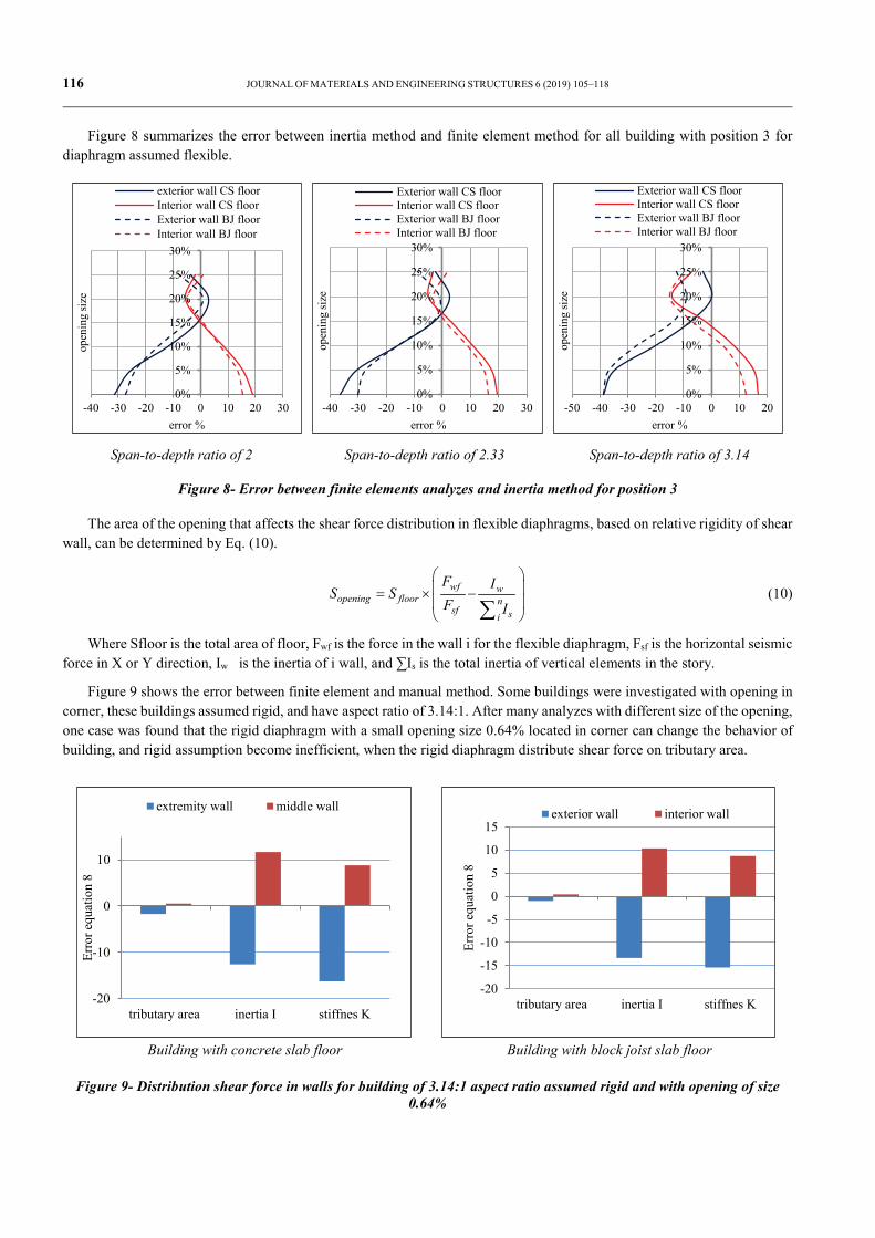
Figure 8 summarizes the error between inertia method and finite element method for all building with position 3 for diaphragm assumed flexible.
Span-to-depth ratio of 2 Span-to-depth ratio of 2.33 Span-to-depth ratio of 3.14
Figure 8- Error between finite elements analyzes and inertia method for position 3
The area of the opening that affects the shear force distribution in flexible diaphragms, based on relative rigidity of shear wall, can be determined by Eq. (10).
wf wopening floor n
sf si
F IS S
F I
= × − ∑
(10)
Where Sfloor is the total area of floor, Fwf is the force in the wall i for the flexible diaphragm, Fsf is the horizontal seismic force in X or Y direction, Iw is the inertia of i wall, and ∑Is is the total inertia of vertical elements in the story.
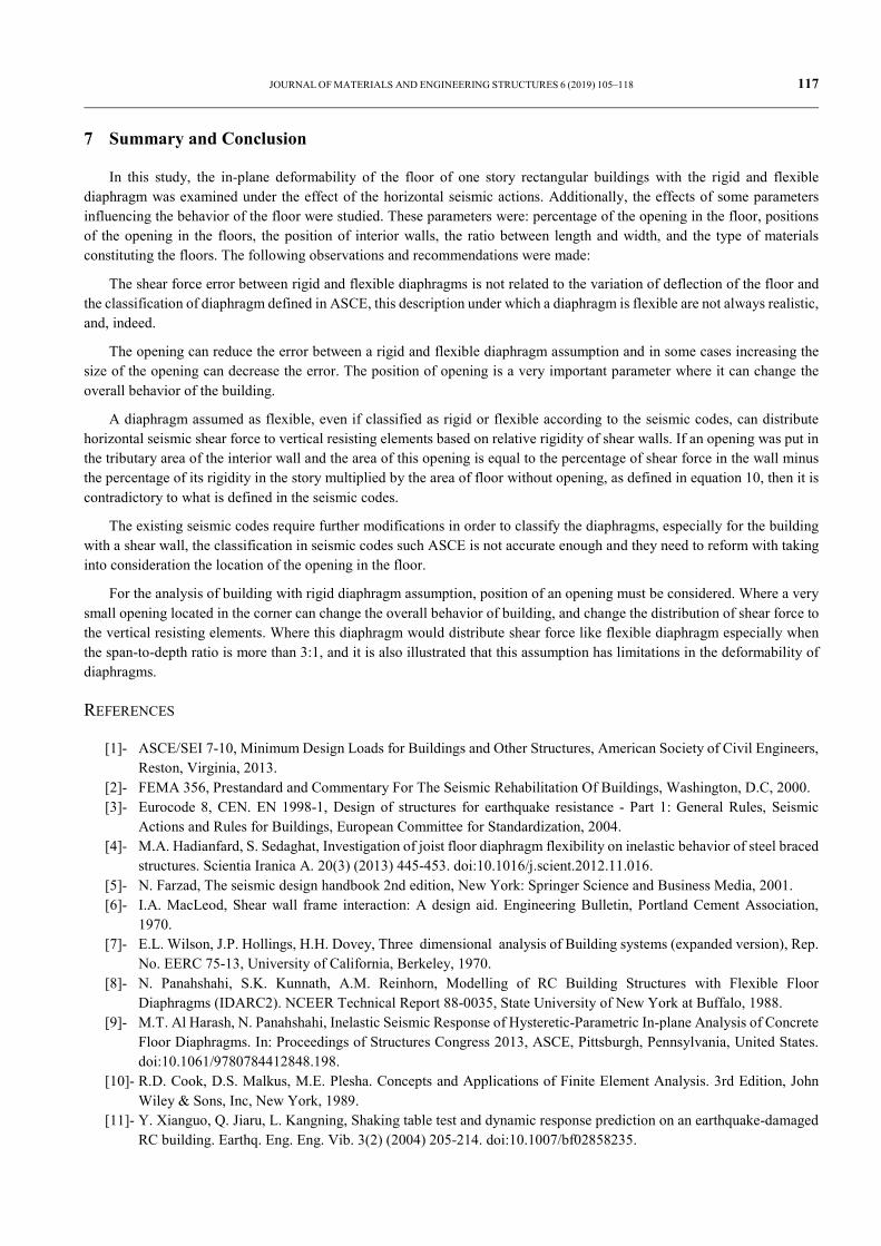
Figure 9 shows the error between finite element and manual method. Some buildings were investigated with opening in corner, these buildings assumed rigid, and have aspect ratio of 3.14:1. After many analyzes with different size of the opening, one case was found that the rigid diaphragm with a small opening size 0.64% located in corner can change the behavior of building, and rigid assumption become inefficient, when the rigid diaphragm distribute shear force on tributary area.
Building with concrete slab floor Building with block joist slab floor
Figure 9- Distribution shear force in walls for building of 3.14:1 aspect ratio assumed rigid and with opening of size 0.64%
0%
5%
10%
15%
20%
25%
30%
-40 -30 -20 -10 0 10 20 30
open
ing
size
error %
exterior wall CS floorInterior wall CS floorExterior wall BJ floorInterior wall BJ floor
0%
5%
10%
15%
20%
25%
30%
-40 -30 -20 -10 0 10 20 30
open
ing
size
error %
Exterior wall CS floorInterior wall CS floorExterior wall BJ floorInterior wall BJ floor
0%
5%
10%
15%
20%
25%
30%
-50 -40 -30 -20 -10 0 10 20
open
ing
size
error %
Exterior wall CS floorInterior wall CS floorExterior wall BJ floorInterior wall BJ floor
-20
-10
0
10
tributary area inertia I stiffnes K
Erro
r equ
atio
n 8
extremity wall middle wall
-20
-15
-10
-5
0
5
10
15
tributary area inertia I stiffnes K
Erro
r equ
atio
n 8
exterior wall interior wall
JOURNAL OF MATERIALS AND ENGINEERING STRUCTURES 6 (2019) 105–118 117
7 Summary and Conclusion
In this study, the in-plane deformability of the floor of one story rectangular buildings with the rigid and flexible diaphragm was examined under the effect of the horizontal seismic actions. Additionally, the effects of some parameters influencing the behavior of the floor were studied. These parameters were: percentage of the opening in the floor, positions of the opening in the floors, the position of interior walls, the ratio between length and width, and the type of materials constituting the floors. The following observations and recommendations were made:
The shear force error between rigid and flexible diaphragms is not related to the variation of deflection of the floor and the classification of diaphragm defined in ASCE, this description under which a diaphragm is flexible are not always realistic, and, indeed.
The opening can reduce the error between a rigid and flexible diaphragm assumption and in some cases increasing the size of the opening can decrease the error. The position of opening is a very important parameter where it can change the overall behavior of the building.
A diaphragm assumed as flexible, even if classified as rigid or flexible according to the seismic codes, can distribute horizontal seismic shear force to vertical resisting elements based on relative rigidity of shear walls. If an opening was put in the tributary area of the interior wall and the area of this opening is equal to the percentage of shear force in the wall minus the percentage of its rigidity in the story multiplied by the area of floor without opening, as defined in equation 10, then it is contradictory to what is defined in the seismic codes.
The existing seismic codes require further modifications in order to classify the diaphragms, especially for the building with a shear wall, the classification in seismic codes such ASCE is not accurate enough and they need to reform with taking into consideration the location of the opening in the floor.
For the analysis of building with rigid diaphragm assumption, position of an opening must be considered. Where a very small opening located in the corner can change the overall behavior of building, and change the distribution of shear force to the vertical resisting elements. Where this diaphragm would distribute shear force like flexible diaphragm especially when the span-to-depth ratio is more than 3:1, and it is also illustrated that this assumption has limitations in the deformability of diaphragms.
REFERENCES
[1]- ASCE/SEI 7-10, Minimum Design Loads for Buildings and Other Structures, American Society of Civil Engineers, Reston, Virginia, 2013.
[2]- FEMA 356, Prestandard and Commentary For The Seismic Rehabilitation Of Buildings, Washington, D.C, 2000. [3]- Eurocode 8, CEN. EN 1998-1, Design of structures for earthquake resistance - Part 1: General Rules, Seismic
Actions and Rules for Buildings, European Committee for Standardization, 2004. [4]- M.A. Hadianfard, S. Sedaghat, Investigation of joist floor diaphragm flexibility on inelastic behavior of steel braced
structures. Scientia Iranica A. 20(3) (2013) 445-453. doi:10.1016/j.scient.2012.11.016. [5]- N. Farzad, The seismic design handbook 2nd edition, New York: Springer Science and Business Media, 2001. [6]- I.A. MacLeod, Shear wall frame interaction: A design aid. Engineering Bulletin, Portland Cement Association,
1970. [7]- E.L. Wilson, J.P. Hollings, H.H. Dovey, Three dimensional analysis of Building systems (expanded version), Rep.
No. EERC 75-13, University of California, Berkeley, 1970. [8]- N. Panahshahi, S.K. Kunnath, A.M. Reinhorn, Modelling of RC Building Structures with Flexible Floor
Diaphragms (IDARC2). NCEER Technical Report 88-0035, State University of New York at Buffalo, 1988. [9]- M.T. Al Harash, N. Panahshahi, Inelastic Seismic Response of Hysteretic-Parametric In-plane Analysis of Concrete
Floor Diaphragms. In: Proceedings of Structures Congress 2013, ASCE, Pittsburgh, Pennsylvania, United States. doi:10.1061/9780784412848.198.
[10]- R.D. Cook, D.S. Malkus, M.E. Plesha. Concepts and Applications of Finite Element Analysis. 3rd Edition, John Wiley & Sons, Inc, New York, 1989.
[11]- Y. Xianguo, Q. Jiaru, L. Kangning, Shaking table test and dynamic response prediction on an earthquake-damaged RC building. Earthq. Eng. Eng. Vib. 3(2) (2004) 205-214. doi:10.1007/bf02858235.
118 JOURNAL OF MATERIALS AND ENGINEERING STRUCTURES 6 (2019) 105–118
[12]- H. Castaños, C. Lomnitz, Unplanned and unforeseen effects of instabilities. Nat. Hazards 11(1) (1995) 45-56. doi:10.1007/bf00613309.
[13]- H.S. Saffarini, M.M. Qudaimat, In-Plane Floor Deformations in RC Structures. J. Struct. Eng. 118(11) (1992) 3089-3102. doi:10.1061/(asce)0733-9445(1992)118:11(3089).
[14]- S.H. Ju, M.C. Lin, Comparison of Building Analyses Assuming Rigid or Flexible Floors. J. Struct. Eng. 125 (1) (1999) 25-31. doi:10.1061/(asce)0733-9445(1999)125:1(25).
[15]- M. Moeini, B. Rafezy, W.P. Howson, Investigation Into The Floor Diaphragm Flexibility In Rectangular Reinforced Concrete Buildings And Error Formula. In: Proceedings of The 14th World Conference on Earthquake Engineering. October 12-17 (2008), Beijing, China.
[16]- S.C. Kim, D.W. White, Linear static analysis of low-rise buildings with flexible diaphragms using the structural separation method. Eng. Struct. 26 (1) (2004) 83-93. doi:10.1016/j.engstruct.2003.08.013.
[17]- S.K. Jain, P.C. Jennings, Analytical models for low-rise buildings with flexible floor diaphragms. Earthq. Eng. Struct. D. 13(2) (1985) 225-241. doi:10.1002/eqe.4290130207.
[18]- M.T. Al Harash, N. Panahshahi, Inelastic seismic response of reinforced concrete buildings with symmetric and unsymmetrical floor diaphragm openings. In: Proceedings of 15th World Conference on Earthquake Engineering. September 24-28, 2012, Lisbon, Portugal.
[19]- J.M. Barron, M. D. Hueste, Diaphragm Effects in Rectangular Reinforced Concrete Buildings. ACI Struct. J. 101(5) (2004) 615-624.
[20]- FEMA 273, Federal Emergency Management Agency, NEHRP guidelines for the seismic rehabilitation of buildings. FEMA publication 273, Washington, D.C, 1997.
[21]- V.K. Sadashiva, G.A. MacRae, B.L. Deam, M.S. Spooner, Quantifying the seismic response of structures with flexible diaphragms. Earthq. Eng. Struct. D. 41(10) (2012) 1365-1389. doi:10.1002/eqe.1187.
[22]- R. Khajehdehi, N. Panahshahi, Effect of openings on in-plane structural behavior of reinforced concrete floor slabs. J. Build. Eng. 7(2016) 1-11. doi:10.1016/j.jobe.2016.04.011.
[23]- J. Humar, M. Popovski, Seismic response of single-storey buildings with flexible diaphragms. Can. J. Civil Eng. 40(9) (2013) 875-886. doi:10.1139/cjce-2012-0493.
[24]- ETABS, Analysis reference manual. R 15.2.2. Copyright Computers and Structures, Inc. Berkeley, California, 2015. [25]- RPA 2003, DTR, MHU, CGS, Algerian earthquake resistant regulations 99/Version 2003. [26]- A. Ayadi, M. Bezzeghoud, Seismicity of Algeria from 1365 to 2013: Maximum Observed Intensity Map
(MOI2014). Seismol. Res. Lett. 86(1) (2014) 236-244. doi:10.1785/0220140075. [27]- A. Tena-Colunga, D.P. Abrams, Seismic Behavior of Structures with Flexible Diaphragms. J. Struct. Eng. 122(4)
(1996) 439-445. doi: 10.1061/(asce)0733-9445(1996)122:4(439) [28]- R.B. Fleischman, K.T. Farrow, Dynamic behavior of perimeter lateral-system structures with flexible diaphragms.
Earthq. Eng. Struct. D. 30(5) (2001) 745-763. doi:10.1002/eqe.36. [29]- S.K. Kunnath, N. Panahshahi, A.M. Reinhorn, Seismic Response of RC Buildings with Inelastic Floor Diaphragms.
J. Struct. Eng. 117(4) (1991) 1218-1237. doi:10.1061/(asce)0733-9445(1991)117:4(1218). [30]- CBC. California Building Code, California Code of Regulations, Title 24, Volume 1 of Part 2, Sacramento,
California, 2013. [31]- IBC 2012, international building code, copyright by International Code Council, Inc, Illinois, 2011. [32]- SNZ 1170.5 Supplement 1:2004, Structural Design Actions. Part 5: Earthquake actions-New Zealand-Commentary,
Standards New Zealand, Wellington, 2004. [33]- H. Thonier, Design and calculation of building structures. (in French), Presses of the National School of Bridges
and Roads, Paris, 1996. [34]- T. Paulay, M.J.N. Priestley, Seismic design of reinforced concrete and masonry buildings, John Wiley & Sons. Inc,
New York, 1992.