Embed Size (px)
Citation preview
Horizontal Diaphragms of Complex shape
by Bart Quimby, P.E., Ph.D
UAA School of Engineering
CE 434 - Timber Design

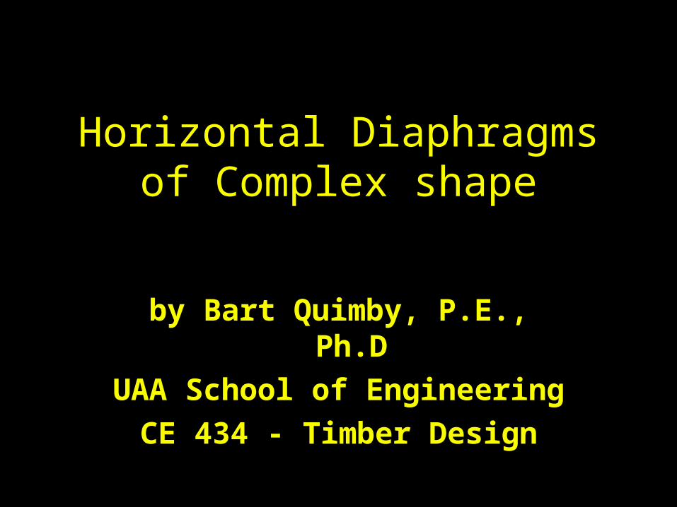
Multispan Wood Diaphragms
• Considered to be a series of simply supported beams.
• Design each diaphragm as separately.
Another View
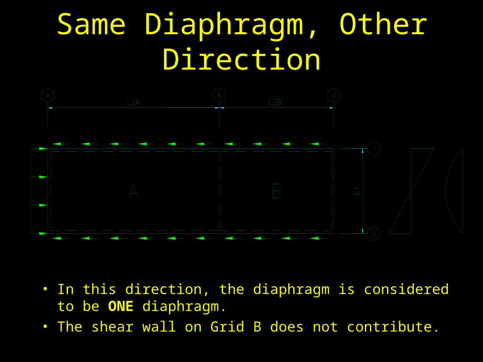
Same Diaphragm, Other Direction
• In this direction, the diaphragm is considered to be ONE diaphragm.
• The shear wall on Grid B does not contribute.
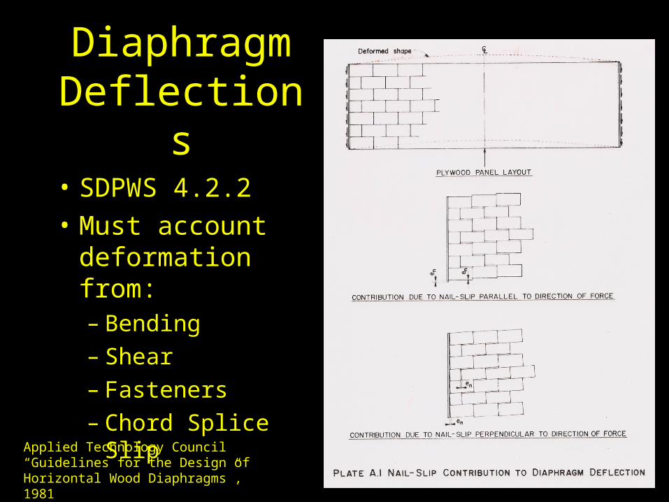
Diaphragm Deflections
• SDPWS 4.2.2
• Must account deformation from:– Bending – Shear– Fasteners– Chord Splice Slip
Applied Technology Council“Guidelines for the Design of Horizontal Wood Diaphragms”, 1981
Drag StrutsGetting the Diaphragm Shear into the Shear walls
• Drag struts are axial force members that “collect” the horizontal diaphragm shears and redistribute them to the shear walls.
• Drag struts are PARALLEL to the direction of force.
• Need to draw an AXIAL FORCE DIAGRAM in order to compute the force a drag strut.
• The member used for the drag strut is often used as a diaphragm chord when the direction of force changes to the other principle direction.
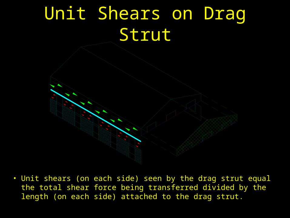
Unit Shears on Drag Strut
• Unit shears (on each side) seen by the drag strut equal the total shear force being transferred divided by the length (on each side) attached to the drag strut.
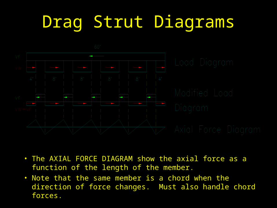
Drag Strut Diagrams
• The AXIAL FORCE DIAGRAM show the axial force as a function of the length of the member.
• Note that the same member is a chord when the direction of force changes. Must also handle chord forces.
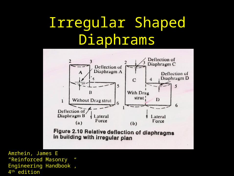
Irregular Shaped Diaphrams
Amrhein, James E“Reinforced Masonry Engineering Handbook”, 4th edition
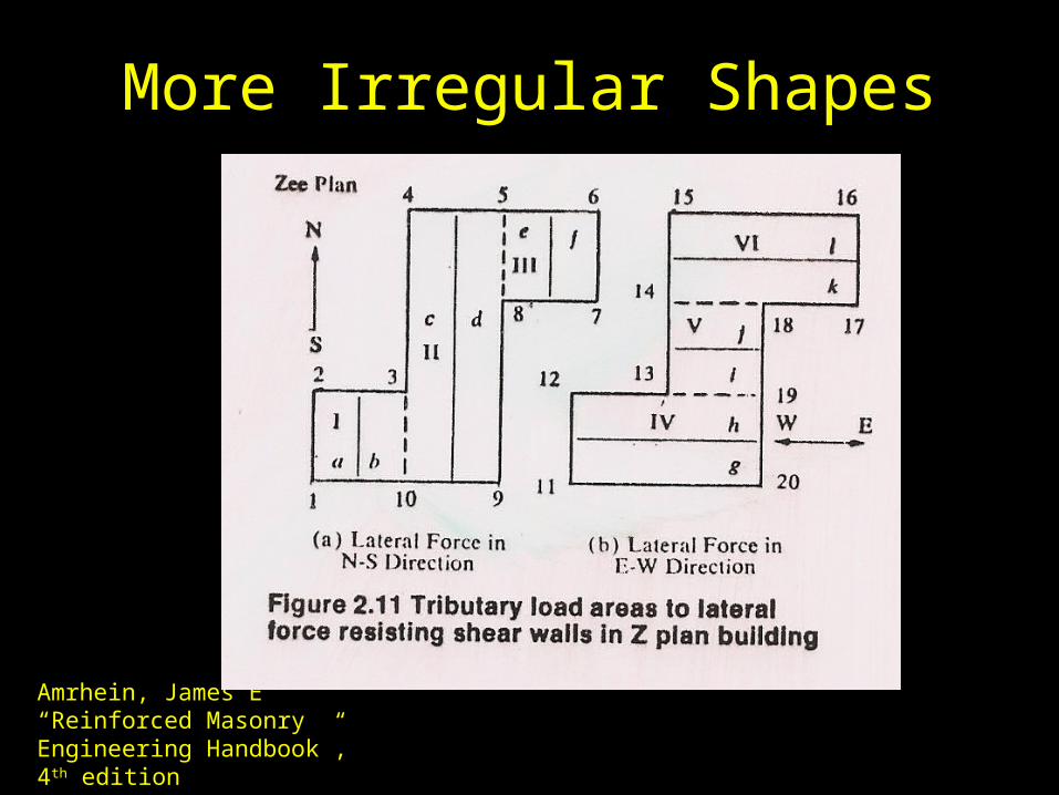
More Irregular Shapes
Amrhein, James E“Reinforced Masonry Engineering Handbook”, 4th edition
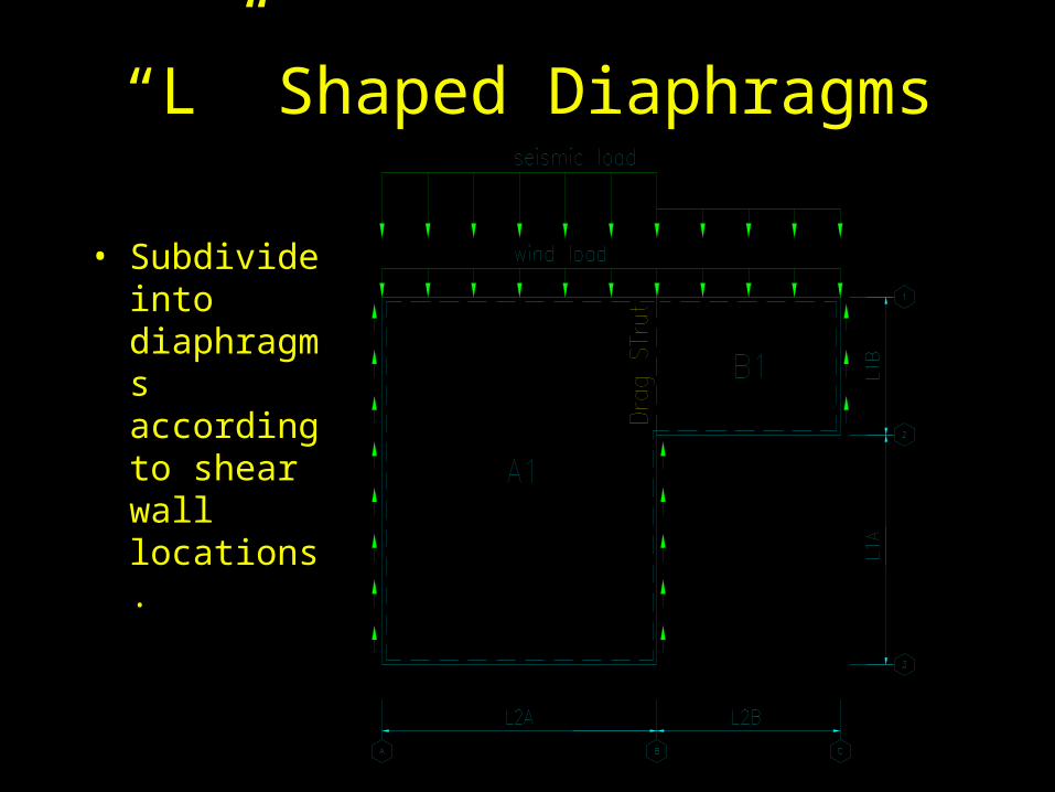
“L” Shaped Diaphragms
• Subdivide into diaphragms according to shear wall locations.
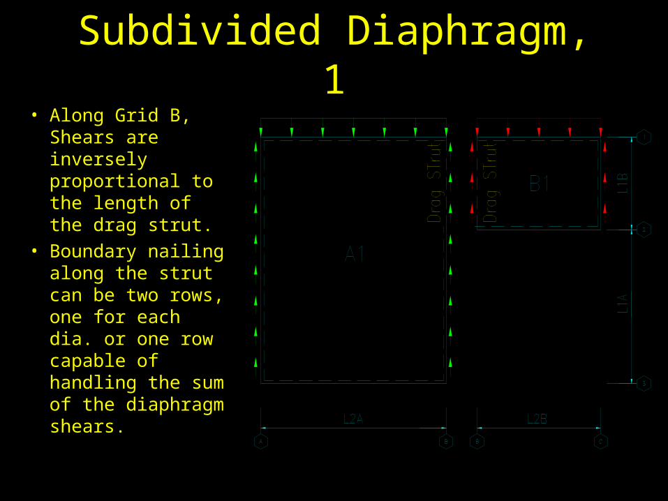
Subdivided Diaphragm, 1• Along Grid B,
Shears are inversely proportional to the length of the drag strut.
• Boundary nailing along the strut can be two rows, one for each dia. or one row capable of handling the sum of the diaphragm shears.

Drag Strut Diagram, 1
• The peak force equals L1B*(vA1+vA2) or L1A*(vwall-vA1).
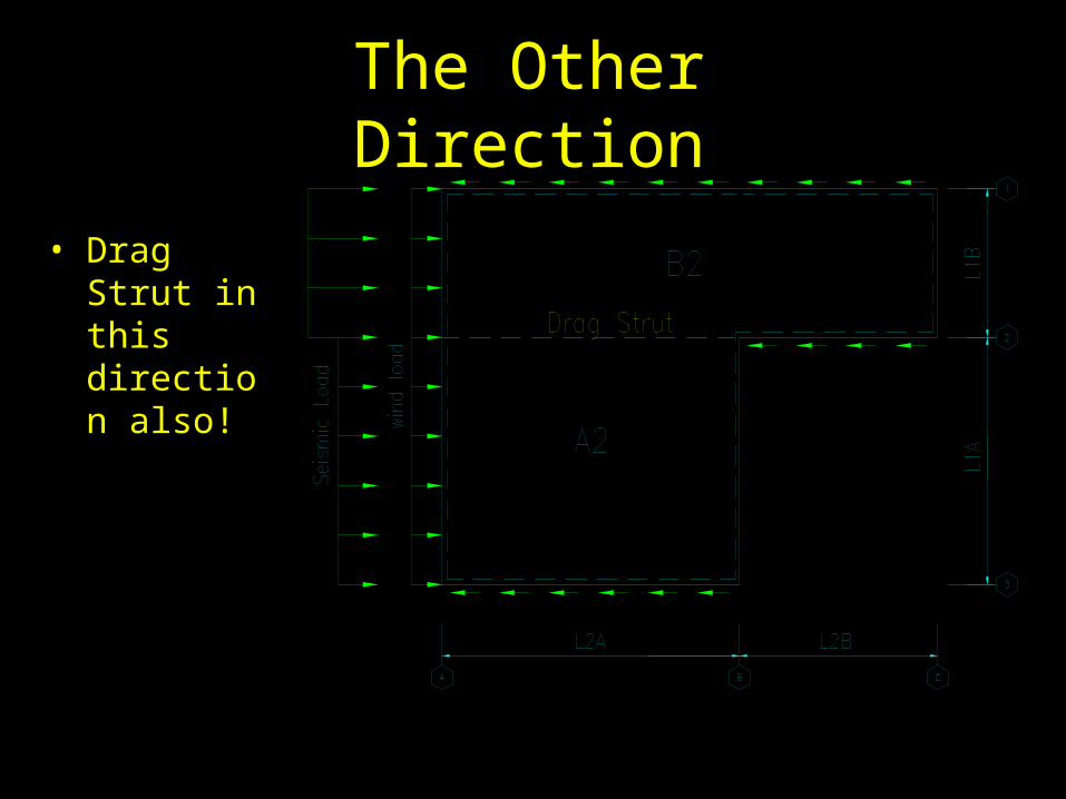
The Other Direction
• Drag Strut in this direction also!
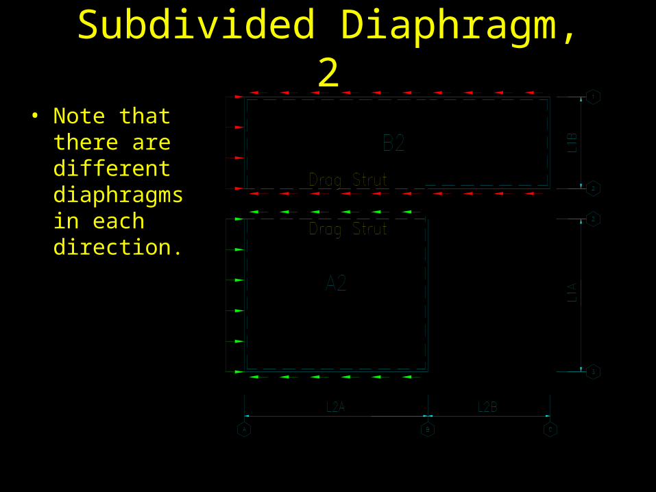
Subdivided Diaphragm, 2
• Note that there are different diaphragms in each direction.

Load Transfer at Vertical Offset
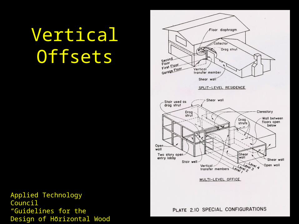
Vertical Offsets
Applied Technology Council“Guidelines for the Design of Horizontal Wood Diaphragms”, 1981

Diaphragms of Variable Depth
• Length parallel to force varies.
• Unit Shear varies with the depth.

Chord Extensions• Chord Force varies with
depth.
• Extensions must be designed to anchor the chord into the diaphragm.
• Length of chord extension affects shear force in diaphragm.
• Diaphragm shear due to extension = Chord force/length of extension.
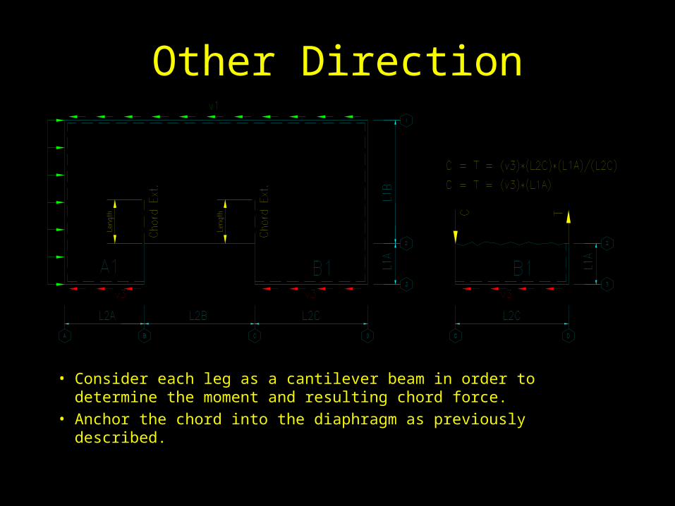
Other Direction
• Consider each leg as a cantilever beam in order to determine the moment and resulting chord force.
• Anchor the chord into the diaphragm as previously described.
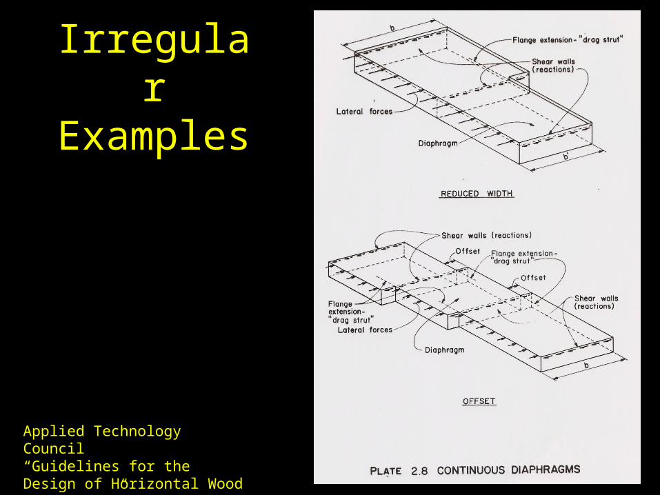
Irregular Examples
Applied Technology Council“Guidelines for the Design of Horizontal Wood Diaphragms”, 1981
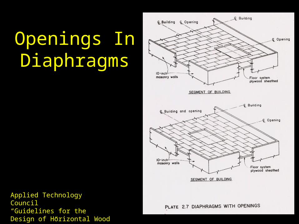
Openings In Diaphragms
Applied Technology Council“Guidelines for the Design of Horizontal Wood Diaphragms”, 1981