Embed Size (px)
Citation preview
Shahrjerdi and Bahramibabamiri International Journal of Mechanicaland Materials Engineering (2015) 10:6 DOI 10.1186/s40712-015-0033-z
ORIGINAL ARTICLE Open Access
The effect of different geometrical imperfectionof buckling of composite cylindrical shellssubjected to axial loadingA. Shahrjerdi* and B. Bahramibabamiri
Abstract
Background: Advanced lightweight laminated composite shells are increasingly being used in modern aerospacestructures to enhance their structural efficiency and performance. Such thin-walled structures are susceptible tobuckling when subjected to static and dynamic compressive stresses. This paper reports on the numerical (finiteelement method (FEM)) study on buckling of carbon fibre-reinforced plastic (CFRP) layered composite cylindersunder displacement and load-controlled static axial compression.
Methods: The effects of geometric properties, lamina lay-up, amplitudes of imperfection and parametric research ofthe shape (square, circular) and the dimensions (axial and circumferential sizes, diameter) of the opening on thestrength of the cylinders under compression were studied. The measurement of imperfections on the cylindricalsurface is achieved using the interpolation method and Fourier series.
Results: The analysis indicates that the critical load is sensitive to the circumferential size of the opening. The function(critical load-circumferential size of the opening) is linear for large openings and independent of the geometricalimperfections of the shell. However, for small openings, it is necessary to take into account the coupling betweenthe initial geometrical imperfections and the openings.
Conclusions: The linear approach does not fit due to the importance of the evolution of the displacements nearthe openings. Also, it was shown that the buckling behaviour of thin composite cylindrical shells can be evaluatedaccurately via modelling to determine the imperfections and the material properties in FEM.
Keywords: Buckling; Composite cylindrical shell; Imperfection; Opening
BackgroundComposite cylindrical shells, used in weight sensitivestructures such as aircraft fuselages, submarine hulls andspace launch vehicles, are constantly subjected to mem-brane stresses. They are made efficient due to their highstrength-to-weight and stiffness-to-weight ratios (Jones1975). However, they are vulnerable to instabilities (buck-ling) when subjected to static or dynamic compressivestresses (Weaver 2000). Due to the fact that there are nosubstances that can satisfy all of these requirements, asubstitute material should be determined, which in thiscase, was determined to be composites. In many industrialapplications, shells are equipped with openings of various
* Correspondence: [email protected] of Mechanical Engineering, Malayer University, Malayer, Iran
© 2015 Shahrjerdi and Bahramibabamiri; licensCreative Commons Attribution License (http://cdistribution, and reproduction in any medium,
shapes, sizes and locations within the lateral surface. Cut-outs in aerial structures such as aircraft and missiles arecreated to provide fuel or windows, and these structuresare subjected to a combination of loads in plane, out ofplane and shear during application. Due to the geometryand general loads of these structures, buckling is one ofthe most important failure criteria. A cylindrical shellunder compression in the meridional direction can fail byoverall buckling (global/Euler), local buckling or the ma-terial strength being exceeded. Various failure mechanismsof composite cylindrical shells, as affected by initial geo-metric imperfections, boundary conditions, lamina stack-ing sequence, anisotropic coupling effects, differentcutouts and load eccentricity, were identified by Weaver(2000), in terms of laminate configurations and shell pro-portions. The buckling response of the shells is very
ee Springer. This is an Open Access article distributed under the terms of thereativecommons.org/licenses/by/4.0), which permits unrestricted use,provided the original work is properly credited.
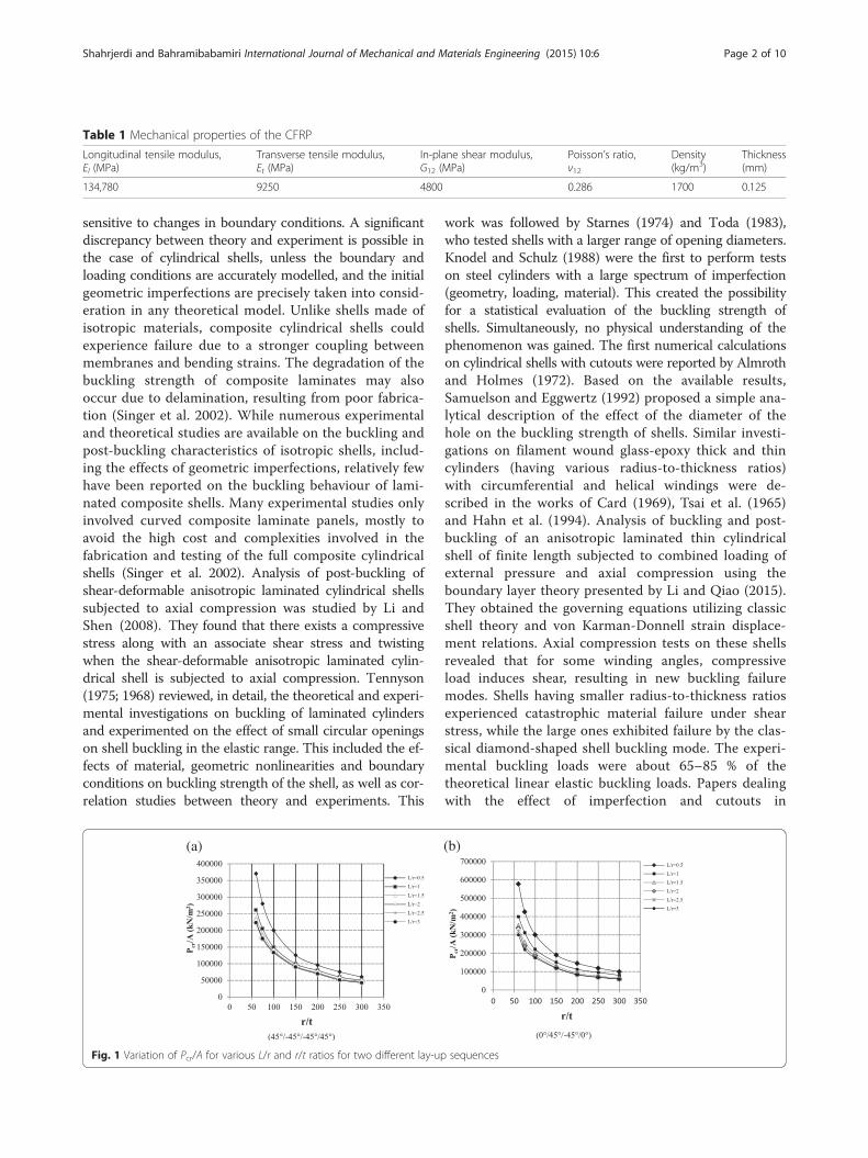
Table 1 Mechanical properties of the CFRP
Longitudinal tensile modulus,El (MPa)
Transverse tensile modulus,Et (MPa)
In-plane shear modulus,G12 (MPa)
Poisson’s ratio,ν12
Density(kg/m3)
Thickness(mm)
134,780 9250 4800 0.286 1700 0.125
Shahrjerdi and Bahramibabamiri International Journal of Mechanical and Materials Engineering (2015) 10:6 Page 2 of 10
sensitive to changes in boundary conditions. A significantdiscrepancy between theory and experiment is possible inthe case of cylindrical shells, unless the boundary andloading conditions are accurately modelled, and the initialgeometric imperfections are precisely taken into consid-eration in any theoretical model. Unlike shells made ofisotropic materials, composite cylindrical shells couldexperience failure due to a stronger coupling betweenmembranes and bending strains. The degradation of thebuckling strength of composite laminates may alsooccur due to delamination, resulting from poor fabrica-tion (Singer et al. 2002). While numerous experimentaland theoretical studies are available on the buckling andpost-buckling characteristics of isotropic shells, includ-ing the effects of geometric imperfections, relatively fewhave been reported on the buckling behaviour of lami-nated composite shells. Many experimental studies onlyinvolved curved composite laminate panels, mostly toavoid the high cost and complexities involved in thefabrication and testing of the full composite cylindricalshells (Singer et al. 2002). Analysis of post-buckling ofshear-deformable anisotropic laminated cylindrical shellssubjected to axial compression was studied by Li andShen (2008). They found that there exists a compressivestress along with an associate shear stress and twistingwhen the shear-deformable anisotropic laminated cylin-drical shell is subjected to axial compression. Tennyson(1975; 1968) reviewed, in detail, the theoretical and experi-mental investigations on buckling of laminated cylindersand experimented on the effect of small circular openingson shell buckling in the elastic range. This included the ef-fects of material, geometric nonlinearities and boundaryconditions on buckling strength of the shell, as well as cor-relation studies between theory and experiments. This
(a)
Fig. 1 Variation of Pcr/A for various L/r and r/t ratios for two different lay-up
work was followed by Starnes (1974) and Toda (1983),who tested shells with a larger range of opening diameters.Knodel and Schulz (1988) were the first to perform testson steel cylinders with a large spectrum of imperfection(geometry, loading, material). This created the possibilityfor a statistical evaluation of the buckling strength ofshells. Simultaneously, no physical understanding of thephenomenon was gained. The first numerical calculationson cylindrical shells with cutouts were reported by Almrothand Holmes (1972). Based on the available results,Samuelson and Eggwertz (1992) proposed a simple ana-lytical description of the effect of the diameter of thehole on the buckling strength of shells. Similar investi-gations on filament wound glass-epoxy thick and thincylinders (having various radius-to-thickness ratios)with circumferential and helical windings were de-scribed in the works of Card (1969), Tsai et al. (1965)and Hahn et al. (1994). Analysis of buckling and post-buckling of an anisotropic laminated thin cylindricalshell of finite length subjected to combined loading ofexternal pressure and axial compression using theboundary layer theory presented by Li and Qiao (2015).They obtained the governing equations utilizing classicshell theory and von Karman-Donnell strain displace-ment relations. Axial compression tests on these shellsrevealed that for some winding angles, compressiveload induces shear, resulting in new buckling failuremodes. Shells having smaller radius-to-thickness ratiosexperienced catastrophic material failure under shearstress, while the large ones exhibited failure by the clas-sical diamond-shaped shell buckling mode. The experi-mental buckling loads were about 65–85 % of thetheoretical linear elastic buckling loads. Papers dealingwith the effect of imperfection and cutouts in
(b)
sequences
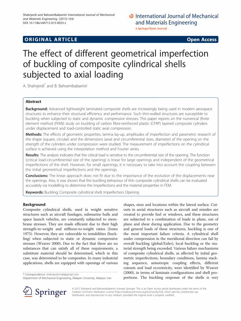
Fig. 2 Buckling modes and loads obtained through static analysis ofmodels without imperfections
Fig. 3 a The details of the covering plates attached to the top and bottomfaces of the shell
Shahrjerdi and Bahramibabamiri International Journal of Mechanical and Materials Engineering (2015) 10:6 Page 3 of 10
laminated composite structures (Leissa 1985) are avail-able in the literature, based on Koiter’s (1970) imper-fection shell theory. These indicate reasonably goodestimates of the buckling loads for axial compressionand bending loading. The effects of local geometric im-perfections on the buckling and post-buckling of com-posite laminated cylindrical shells subjected tocombined axial compression and uniform temperature riseusing Reddy’s higher-order shear deformation shell theoryand employing a von Karman type of kinematic nonlinear-ity investigated by Shen and Li (2002). The main difficultyin developing post-buckling theories, required to assess theimperfection sensitivity of composite cylindrical shells, isthe lack of reliable imperfection data (Singer et al. 2002). Inthe 1970s and 1980s, several analytical and experimentalstudies were conducted on the buckling behaviour of com-posite cylinders fabricated from prepregs, considering theeffect of assumed axisymmetric initial geometric imperfec-tions having similar RMS value amplitudes, as measured inthe works of Tennyson et al. (1971) and Tennyson andHansen (1983). The discrepancy between the theory andexperiments were about 20 %. Geier et al. (2002; 1991) alsorevealed that sensitivity to geometric and loading imperfec-tions was influenced by the laminates’ lay-up and the factthat a strong interaction exists between shape and loadingimperfections. In the absence of such data, approximateknockdown factors were used to determine the criticalbuckling load. In order to include a nonlinear, pre-bucklingbehaviour and imperfection sensitivity of general shells, an
of the shell. b The locations of strain gauges on the inner and outer
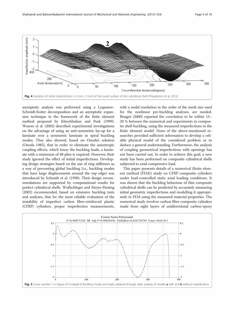
Fig. 4 Variation of initial imperfection (−2 mm, 2 mm) of the outer surface of the cylindrical shell (Priyadarsini et al. 2012)
Shahrjerdi and Bahramibabamiri International Journal of Mechanical and Materials Engineering (2015) 10:6 Page 4 of 10
asymptotic analysis was performed using a Lyapunov-Schmidt-Koiter decomposition and an asymptotic expan-sion technique in the framework of the finite elementmethod proposed by Kheyrkhahan and Peek (1999).Weaver et al. (2002) described experimental investigationson the advantage of using an anti-symmetric lay-up for alaminate over a symmetric laminate in spiral bucklingmodes. They also showed, based on Onoda’s solution(Onoda 1985), that in order to eliminate the anisotropiccoupling effects, which lower the buckling loads, a lamin-ate with a minimum of 48 plies is required. However, theirstudy ignored the effect of initial imperfections. Develop-ing design strategies based on the use of ring stiffeners asa way of preventing global buckling (i.e., buckling modesthat have large displacements around the top edge) wasintroduced by Schmidt et al. (1998). Their design recom-mendations are supported by computational results forperfect cylindrical shells. Wullschleger and Meyer-Piening(2002) recommended, based on extensive buckling testsand analyses, that for the most reliable evaluation of theinstability of imperfect carbon fibre-reinforced plastic(CFRP) cylinders, proper imperfection measurements,
Fig. 5 Curve number 1 in Figure of 4 instead of Buckling modes and loads obt
with a nodal resolution in the order of the mesh size usedfor the nonlinear pre-buckling analyses, are needed.Bisagni (2000) reported the correlation to be within 15–20 % between the numerical and experiments in compos-ite shell buckling, using the measured imperfections in thefinite element model. None of the above-mentioned re-searches provided sufficient information to develop a reli-able physical model of the considered problem or todeduce a general understanding. Furthermore, the analysisof coupling geometrical imperfections with openings hasnot been carried out. In order to achieve this goal, a newstudy has been performed on composite cylindrical shellssubjected to axial compressive load.This paper presents details of a numerical (finite elem-
ent method (FEM)) study on CFRP composite cylindersunder load-controlled static axial loading conditions. Itwas shown that the buckling behaviour of thin compositecylindrical shells can be predicted by accurately measuringinitial geometric imperfections and modelling it appropri-ately in FEM using the measured material properties. Thenumerical study involves carbon fibre composite cylindersmade from eight layers of unidirectional carbon-epoxy
ained through static analysis of models a with and b without imperfections
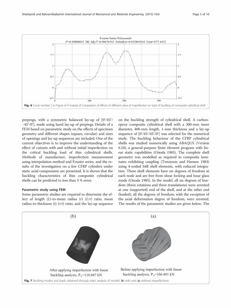
Fig. 6 Curve number 2 in Figure of 4 instead of Comparison of effects of different value of imperfection on load of buckling of composite cylindrical shell
Shahrjerdi and Bahramibabamiri International Journal of Mechanical and Materials Engineering (2015) 10:6 Page 5 of 10
prepregs, with a symmetric balanced lay-up of [0°/45°/−45°/0°], made using hand lay-up of prepregs. Details of aFEM based on parametric study on the effects of specimengeometry and different shapes (square, circular) and sizesof openings and lay-up sequences are included. One of thecurrent objectives is to improve the understanding of theeffect of cutouts with and without initial imperfection onthe critical buckling load of thin cylindrical shells.Methods of manufacture, imperfection measurementusing interpolation method and Fourier series, and the re-sults of the investigation on a few CFRP cylinders understatic axial compression are presented. It is shown that thebuckling characteristics of thin composite cylindricalshells can be predicted to less than 5 % error.
Parametric study using FEMSome parametric studies are required to determine the ef-fect of length (L)-to-mean radius (r) (L/r) ratio, meanradius-to-thickness (t) (r/t) ratio, and the lay-up sequence
Fig. 7 Buckling modes and loads obtained through static analysis of mode
on the buckling strength of cylindrical shell. A carbon-epoxy composite cylindrical shell with a 300-mm innerdiameter, 400-mm length, 1-mm thickness and a lay-upsequence of [0°/45°/45°/0°] was selected for the numericalstudy. The buckling behaviour of the CFRP cylindricalshells was studied numerically using ABAQUS (Version6.10), a general-purpose finite element program with lin-ear static capabilities (Onoda 1985). The complete shellgeometry was modelled as required in composite lami-nates exhibiting coupling (Tennyson and Hansen 1983)using 4-noded S4R shell elements, with reduced integra-tion. These shell elements have six degrees of freedom ateach node and are free from shear locking and hour glassmode (Onoda 1985). In the model, all six degrees of free-dom (three rotations and three translations) were arrestedat one (supported) end of the shell, and at the other end(loaded), all the degrees of freedom, with the exception ofthe axial deformation degree of freedom, were arrested.The results of the parametric studies are given below. The
ls (b) with and (a) without imperfections
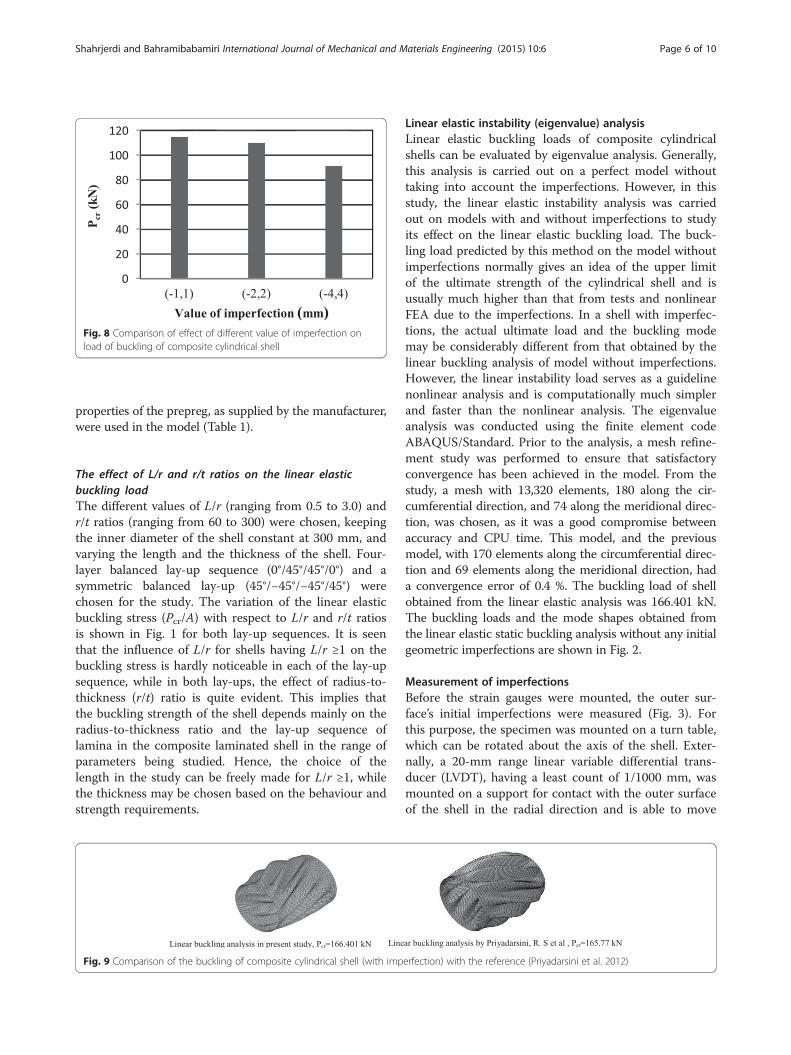
Fig. 8 Comparison of effect of different value of imperfection onload of buckling of composite cylindrical shell
Shahrjerdi and Bahramibabamiri International Journal of Mechanical and Materials Engineering (2015) 10:6 Page 6 of 10
properties of the prepreg, as supplied by the manufacturer,were used in the model (Table 1).
The effect of L/r and r/t ratios on the linear elasticbuckling loadThe different values of L/r (ranging from 0.5 to 3.0) andr/t ratios (ranging from 60 to 300) were chosen, keepingthe inner diameter of the shell constant at 300 mm, andvarying the length and the thickness of the shell. Four-layer balanced lay-up sequence (0°/45°/45°/0°) and asymmetric balanced lay-up (45°/−45°/−45°/45°) werechosen for the study. The variation of the linear elasticbuckling stress (Pcr/A) with respect to L/r and r/t ratiosis shown in Fig. 1 for both lay-up sequences. It is seenthat the influence of L/r for shells having L/r ≥1 on thebuckling stress is hardly noticeable in each of the lay-upsequence, while in both lay-ups, the effect of radius-to-thickness (r/t) ratio is quite evident. This implies thatthe buckling strength of the shell depends mainly on theradius-to-thickness ratio and the lay-up sequence oflamina in the composite laminated shell in the range ofparameters being studied. Hence, the choice of thelength in the study can be freely made for L/r ≥1, whilethe thickness may be chosen based on the behaviour andstrength requirements.
Fig. 9 Comparison of the buckling of composite cylindrical shell (with imp
Linear elastic instability (eigenvalue) analysisLinear elastic buckling loads of composite cylindricalshells can be evaluated by eigenvalue analysis. Generally,this analysis is carried out on a perfect model withouttaking into account the imperfections. However, in thisstudy, the linear elastic instability analysis was carriedout on models with and without imperfections to studyits effect on the linear elastic buckling load. The buck-ling load predicted by this method on the model withoutimperfections normally gives an idea of the upper limitof the ultimate strength of the cylindrical shell and isusually much higher than that from tests and nonlinearFEA due to the imperfections. In a shell with imperfec-tions, the actual ultimate load and the buckling modemay be considerably different from that obtained by thelinear buckling analysis of model without imperfections.However, the linear instability load serves as a guidelinenonlinear analysis and is computationally much simplerand faster than the nonlinear analysis. The eigenvalueanalysis was conducted using the finite element codeABAQUS/Standard. Prior to the analysis, a mesh refine-ment study was performed to ensure that satisfactoryconvergence has been achieved in the model. From thestudy, a mesh with 13,320 elements, 180 along the cir-cumferential direction, and 74 along the meridional direc-tion, was chosen, as it was a good compromise betweenaccuracy and CPU time. This model, and the previousmodel, with 170 elements along the circumferential direc-tion and 69 elements along the meridional direction, hada convergence error of 0.4 %. The buckling load of shellobtained from the linear elastic analysis was 166.401 kN.The buckling loads and the mode shapes obtained fromthe linear elastic static buckling analysis without any initialgeometric imperfections are shown in Fig. 2.
Measurement of imperfectionsBefore the strain gauges were mounted, the outer sur-face’s initial imperfections were measured (Fig. 3). Forthis purpose, the specimen was mounted on a turn table,which can be rotated about the axis of the shell. Exter-nally, a 20-mm range linear variable differential trans-ducer (LVDT), having a least count of 1/1000 mm, wasmounted on a support for contact with the outer surfaceof the shell in the radial direction and is able to move
erfection) with the reference (Priyadarsini et al. 2012)
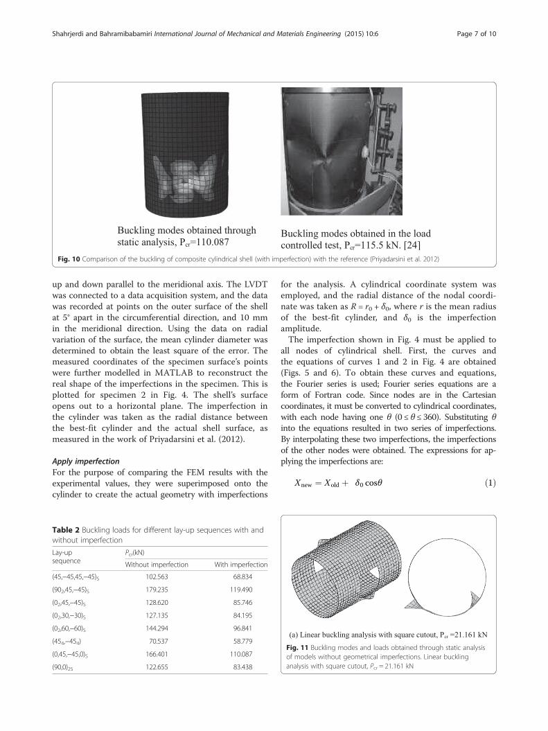
Fig. 10 Comparison of the buckling of composite cylindrical shell (with imperfection) with the reference (Priyadarsini et al. 2012)
Shahrjerdi and Bahramibabamiri International Journal of Mechanical and Materials Engineering (2015) 10:6 Page 7 of 10
up and down parallel to the meridional axis. The LVDTwas connected to a data acquisition system, and the datawas recorded at points on the outer surface of the shellat 5° apart in the circumferential direction, and 10 mmin the meridional direction. Using the data on radialvariation of the surface, the mean cylinder diameter wasdetermined to obtain the least square of the error. Themeasured coordinates of the specimen surface’s pointswere further modelled in MATLAB to reconstruct thereal shape of the imperfections in the specimen. This isplotted for specimen 2 in Fig. 4. The shell’s surfaceopens out to a horizontal plane. The imperfection inthe cylinder was taken as the radial distance betweenthe best-fit cylinder and the actual shell surface, asmeasured in the work of Priyadarsini et al. (2012).
Apply imperfectionFor the purpose of comparing the FEM results with theexperimental values, they were superimposed onto thecylinder to create the actual geometry with imperfections
Table 2 Buckling loads for different lay-up sequences with andwithout imperfection
Lay-upsequence
Pcr(kN)
Without imperfection With imperfection
(45,−45,45,−45)S 102.563 68.834
(902,45,−45)S 179.235 119.490
(02,45,−45)S 128.620 85.746
(02,30,−30)S 127.135 84.195
(02,60,−60)S 144.294 96.841
(454,−454) 70.537 58.779
(0,45,−45,0)S 166.401 110.087
(90,0)2S 122.655 83.438
for the analysis. A cylindrical coordinate system wasemployed, and the radial distance of the nodal coordi-nate was taken as R = r0 + δ0, where r is the mean radiusof the best-fit cylinder, and δ0 is the imperfectionamplitude.The imperfection shown in Fig. 4 must be applied to
all nodes of cylindrical shell. First, the curves andthe equations of curves 1 and 2 in Fig. 4 are obtained(Figs. 5 and 6). To obtain these curves and equations,the Fourier series is used; Fourier series equations are aform of Fortran code. Since nodes are in the Cartesiancoordinates, it must be converted to cylindrical coordinates,with each node having one θ (0 ≤ θ ≤ 360). Substituting θinto the equations resulted in two series of imperfections.By interpolating these two imperfections, the imperfectionsof the other nodes were obtained. The expressions for ap-plying the imperfections are:
Xnew ¼ Xold þ δ0 cosθ ð1Þ
Fig. 11 Buckling modes and loads obtained through static analysisof models without geometrical imperfections. Linear bucklinganalysis with square cutout, Pcr = 21.161 kN
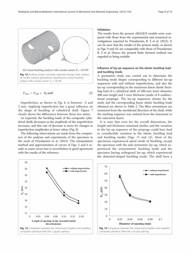
Fig. 12 Buckling modes and loads obtained through static analysisof models without geometrical imperfections. Linear bucklinganalysis with circular cutout, Pcr = 18.549
Shahrjerdi and Bahramibabamiri International Journal of Mechanical and Materials Engineering (2015) 10:6 Page 8 of 10
Y new ¼ Y old þ δ0 sinθ ð2Þ
Imperfection, as shown in Fig. 4, is between −2 and2 mm. Applying imperfection has a great influence onthe shape of buckling of cylindrical shell. Figure 7clearly shows the differences between these two states.As expected, the buckling loads of the composite cylin-
drical shells decreases as the amplitude of the imperfectionincreases, and this rate of decrease is more for changes inimperfection amplitudes at lower values (Fig. 8).The following observations are made from the compari-
son of the analyses and experiments of the specimen inthe work of Priyadarsini et al. (2012). The interpolationmethod and approximation of curves of Figs. 5 and 6 re-sults in some errors but is nevertheless in good agreementwith the results of the reference.
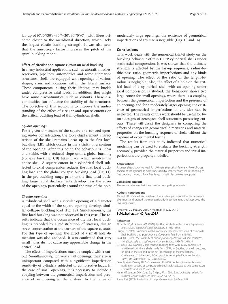
Fig. 13 Comparison between the critical load of perfect and imperfectcomposite cylindrical shell with a square opening
ValidationThe results from the present ABAQUS models were com-pared with those from the experimental and numerical in-vestigations reported by Priyadarsini, R. S et al. (2012). Itcan be seen that the results of the present study, as shownin Figs. 9 and 10, are comparable with those of Priyadarsini,R. S et al. Hence, the present finite element method wasregarded as being suitable.
Influence of lay-up sequence on the elastic buckling loadand buckling modeA parametric study was carried out to determine thebuckling mode shapes corresponding to different lay-upsequences with and without imperfections, and also thelay-up corresponding to the maximum linear elastic buck-ling load of a cylindrical shell, of 300-mm inner diameter,400-mm length and 1-mm thickness (made of 8 unidirec-tional prepregs). The lay-up sequences chosen for thestudy and the corresponding linear elastic buckling loadsobtained are shown in Table 2. The fibre orientations aremeasured from the meridional direction of the shell, whilethe stacking sequence was ordered from the innermost tothe outermost layers.It is seen that even for the overall dimensions, the
length and thickness remained similar, and the variationin the lay-up sequence of the prepregs could have leadto considerable variation in the elastic buckling loadand buckling modes (Figs. 11 and 12). Most of thespecimens experienced spiral mode of buckling, exceptthe specimen with the anti-symmetric lay-up, which ex-perienced the axisymmetric buckling mode and thespecimen having orthogonal lay-up, which experiencedthe diamond-shaped buckling mode. The shell have a
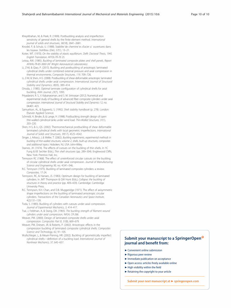
Fig. 14 Comparison between the critical load of perfect and imperfectcomposite cylindrical shell with a circular opening
Shahrjerdi and Bahramibabamiri International Journal of Mechanical and Materials Engineering (2015) 10:6 Page 9 of 10
lay-up of (0°/0°/30°/−30°/−30°/30°/0°/0°), with fibres ori-ented closer to the meridional direction, which lacksthe largest elastic buckling strength. It was also seenthat the anisotropy factor increases the pitch of thespiral buckling mode.
Effect of circular and square cutout on axial bucklingIn many industrial applications such as aircraft, missiles,reservoirs, pipelines, automobiles and some submarinestructures, shells are equipped with openings of variousshapes, sizes and locations within the lateral surface.These components, during their lifetime, may buckleunder compressive axial loads. In addition, they mighthave some discontinuities, such as cutouts. These dis-continuities can influence the stability of the structures.The objective of this section is to improve the under-standing of the effect of circular and square cutouts onthe critical buckling load of thin cylindrical shells.
Square openingsFor a given dimension of the square and centred open-ing under consideration, the force-displacement charac-teristic of the shell remains linear up to the first localbuckling (LB), which occurs in the vicinity of a contourof the opening. After this point, the behaviour is linearand stable, with a reduced slope until a global buckling(collapse buckling, CB) takes place, which involves theentire shell. A square cutout in a cylindrical shell sub-jected to axial compression reduces the first local buck-ling load and the global collapse buckling load (Fig. 11).In the pre-buckling range prior to the first local buck-ling, large radial displacements develop near the edgesof the openings, particularly around the rims of the hole.
Circular openingsA cylindrical shell with a circular opening of a diameterequal to the width of the square opening develops simi-lar collapse buckling load (Fig. 12). Simultaneously, thefirst load buckling was not observed in this case. The re-sults indicate that the occurrence of the first local buck-ling is preceded by a redistribution of stresses, due tostress concentration at the corners of the square cutouts.For this type of opening, the effect of a small hole di-mension was also analysed. It was confirmed that verysmall holes do not cause any appreciable change in thecritical load.The effect of imperfections must be coupled with a cut-
out. Simultaneously, for very small openings, their size isunimportant compared with a significant imperfectionsensitivity of cylinders subjected to compressive loads. Inthe case of small openings, it is necessary to include acoupling between the geometrical imperfection and pres-ence of an opening in the analysis. In the range of
moderately large openings, the existence of geometricalimperfections of any size is negligible (Figs. 13 and 14).
ConclusionsThis work deals with the numerical (FEM) study on thebuckling behaviour of thin CFRP cylindrical shells understatic axial compression. It was shown that the ultimatestrength is affected by the lay-up sequence, radius-to-thickness ratio, geometric imperfections and any kindsof opening. The effect of the ratio of the length-to-radius is negligible. Also, the effect of a hole on the crit-ical load of a cylindrical shell with an opening underaxial compression is studied; the behaviour shows twolarge zones: for small openings, where there is a couplingbetween the geometrical imperfection and the presence ofan opening, and for a moderately larger opening, the exist-ence of geometrical imperfections of any size can beneglected. The results of this work should be useful for fu-ture designs of aerospace shell structures possessing cut-outs. These will assist the designers in comparing theeffects of changes in geometrical dimensions and materialproperties on the buckling response of shells without theexpense of experimental testing.The results from this study indicated that numerical
modelling can be used to evaluate the buckling strengthaccurately, provided the material properties and initial im-perfections are properly modelled.
AbbreviationsP: Linear elastic buckling load; Pcr: Ultimate strength at failure; A: Area of crosssection of the cylinder; U: Amplitude of initial imperfections (corresponding tofirst buckling mode); L: Total free length of cylinder between supports.
Competing interestsThe authors declare that they have no competing interests.
Authors’ contributionsAS and BB modeled and analyzed the studies, participated in the sequencealignment and drafted the manuscript. Both authors read and approved thefinal manuscript.
Received: 25 January 2015 Accepted: 11 May 2015
ReferencesAlmroth, BO, & Holmes, AM. (1972). Buckling of shells with cutouts. Experimental
and analysis. Journal of Solids Structures, 8, 1057–1566.Bisagni, C. (2000). Numerical analysis and experimental correlation of composite
shell buckling and post-buckling. Composite: Part B, 31, 655–667.Card, MF. (1969). The sensitivity of buckling of axially compressed fibre-reinforced
cylindrical shells to small geometric imperfections, NASA TMX-61914.B. Geier, H. Klein and R. Zimmermann, Buckling tests with axially compressed
unstiffened cylindrical shells made from CFRP, in: Buckling of shell structures,on land, in the sea and in the air, Proceedings of the InternationalConference, J.F. Jullien, ed., INSA Lyon, Elsevier Applied Science, London,New York (September 1991), pp. 498-507
Geier, B, Meyer-Piening, HR, & Zimmermann, R. (2002). On the influence of laminatestacking on buckling of composite cylindrical shells subjected to axial compression.Composite Structures, 55, 467–474.
Hahn, HT, Jensen, DW, Claus, SJ, & Hipp, PA. (1994). Structural design criteria forfilament wound composite shells, NASA CR-195125.
Jones, RM. (1975). Mechanics of composite materials (McGraw hill).
Shahrjerdi and Bahramibabamiri International Journal of Mechanical and Materials Engineering (2015) 10:6 Page 10 of 10
Kheyrkhahan, M, & Peek, R. (1999). Postbuckling analysis and imperfectionsensitivity of general shells by the finite element method. Internationaljournal of solids and structures, 36(18), 2641–2681.
Knodel, P, & Schulz, U. (1988). Stabilite´de chemine´es d’acier a` ouvertures dansles tuyaux. Stahlbau (Der), 57(1), 13–21.
Koiter, WT. (1970). On the stability of elastic equilibrium. Delft: Doctoral Thesis, 1945.English Translation: AFFDL-TR-70 25.
Leissa, AW. (1985). Buckling of laminated composite plates and shell panels, ReportAFWAL-TR-85-3069 (AF Wright Aeronautical Laboratories).
Li, Z-M, & Qiao, P. (2015). Buckling and postbuckling of anisotropic laminatedcylindrical shells under combined external pressure and axial compression inthermal environments. Composite Structures, 119, 709–726.
Li, Z-M, & Shen, H-S. (2008). Postbuckling of shear-deformable anisotropic laminatedcylindrical shells under axial compression. International Journal of StructuralStability and Dynamics, 8(03), 389–414.
Onoda, J. (1985). Optimal laminate configuration of cylindrical shells for axialbuckling. AIAA Journal, 23(7), 1093.
Priyadarsini, R. S., V. Kalyanaraman, and S. M. Srinivasan (2012). Numerical andexperimental study of buckling of advanced fiber composite cylinders under axialcompression. International Journal of Structural Stability and Dynamics 12, no.04:401–423.
Samuelson, AL, & Eggwertz, S. (1992). Shell stability handbook (p. 278). London:Elsevier Applied Science.
Schmidt, H, Binder, B, & Lange, H. (1998). Postbuckling strength design of openthin-walled cylindrical tanks under wind load. Thin-Walled Structures, 31(1),203–220.
Shen, H-S, & Li, QS. (2002). Thermomechanical postbuckling of shear deformablelaminated cylindrical shells with local geometric imperfections. InternationalJournal of Solids and Structures, 39(17), 4525–4542.
Singer, J, Arbocz, J, & Weller, T. (2002). Buckling experiments, experimental methods inbuckling of thin-walled structures, volume 2, shells, built-up structures, compositesand additional topics. Hoboken, NJ, USA: John-Wiley.
Starnes, JH. (1974). The effects of cutouts on the buckling of thin shells. In YCFung & EE Sechler (Eds.), Thin shell structures (pp. 289–304). Englewood Cliffs,New York: Prentice Hall, Inc.
Tennyson RC (1968). The effect of unreinforced circular cutouts on the bucklingof circular cylindrical shells under axial compression. Journal of ManufacturingScience and Engineering 90, no. 4:541–546.
R.C. Tennyson (1975). Buckling of laminated composite cylinders: a review.Composites, 17-24.
Tennyson, RC, & Hansen, JS. (1983). Optimum design for buckling of laminatedcylinders. In JMT Thompson & GW Hunt (Eds.), Collapse: the buckling ofstructures in theory and practice (pp. 409–429). Cambridge: CambridgeUniversity Press.
R.C. Tennyson, K.H. Chan, and D.B. Muggeridge (1971). The effect of axisymmetricshape imperfections on the buckling of laminated anisotropic circularcylinders. Transactions of the Canadian Aeronautics and Space Institute,4(2):131–139.
Toda, S. (1983). Buckling of cylinders with cutouts under axial compression.Journal of Experimental Mechanics, 3, 414–417.
Tsai, J, Feldman, A, & Stang, DA. (1965). The buckling strength of filament woundcylinders under axial compression, NASA, CR-266.
Weaver, PM. (2000). Design of laminated composite shells under axialcompression. Composites Part B, 31(8), 669–679.
Weaver, PM, Driesen, JR, & Roberts, P. (2002). Anisotropic effects in thecompression buckling of laminated composite cylindrical shells. CompositesScience and Technology, 62, 91–105.
Wullschleger, L, & Meyer-Piening, HR. (2002). Buckling of geometrically imperfectcylindrical shells—definition of a buckling load. International Journal ofNonlinear Mechanics, 37, 645–657.
Submit your manuscript to a journal and benefi t from:
7 Convenient online submission
7 Rigorous peer review
7 Immediate publication on acceptance
7 Open access: articles freely available online
7 High visibility within the fi eld
7 Retaining the copyright to your article
Submit your next manuscript at 7 springeropen.com