Embed Size (px)
Citation preview

Journal of Applied Fluid Mechanics, Vol. 12, No. 4, pp. 1189-1202, 2019.
Available online at www.jafmonline.net, ISSN 1735-3572, EISSN 1735-3645. DOI: 10.29252/jafm.12.04.29579
CFD Study of the Effect of Geometrical Shape of
Separation Blades on the Rotor Performance of
an Annular Centrifugal Extractor (ACE)
H. Ghaya1†, R. Guizani1, H. Mhiri1 and P. Bournot2
1 University of Monastir, National Engineering School of Monastir (ENIM), UTTPI, Av. Ibn El
Jazzar, 5019 Monastir, Tunisia 2 IUSTI, Technopôle de Château-Gombert, 5 rue Enrico Fermi, 13 013 Marseille, France
†Corresponding Author Email: [email protected]
(Received August 27, 2018; accepted November 23, 2018)
ABSTRACT
Annular centrifugal extractors have a great potential in the multiphase extraction of pharmaceutical,
nuclear, and many other processes. Although the widespread use of this device, the design procedures are
still unavailable because of the complexity of the fluid mechanics in the rotor region called the separation
zone. From a structural point of view, this region has a complicated conception due to the different
internals. This study presents a three-dimensional numerical simulation of the flow field inside the rotor
region of an annular centrifugal extractor ACE. The industrial CFD code (Fluent) was used to model the
highly swirling fluid flow in the settling zone with various geometries of separation blades (straight blades
and curved blades). Numerical predictions and experimental results were compared in order to validate
the proposed models. The velocity field with the k-ε model shows a good agreement with the experimental
data available in the literature. The Volume of Fluid (VOF) method was employed to simulate the physics
of the interface of air/water free surface. A comparison between the flow field and the performances of
the ACE model design with vertical straight blades and with vertical curved blades was further
investigated to study the effect of the geometric shape of the separation blades on the parameters of liquid
holdup volume, the interface radius and the pressure drop. It was found that the geometry of the separating
blades has a significant impact on the pressure drop, liquid hold-up volume and interface radius and
general flow in the extractor-settling zone. The predicted pressure drop proved that the geometry of the
ACE rotor with curved blades leads to a lower values of pressure drop.
Keywords: CFD; ACE rotor ; Multi-phase flow; Pressure drop; The interface radius; Liquid holdup volume.
NOMENCLATURE
a diameter of the light phase outlet
CFD Computational Fluid Dynamics;
D diameter of the rotor
g gravitational acceleration
hd distance between the inlet and the diverter
disc
k turbulent Kinetic energy
MRF Multiple Reference Frame
P pressure
rpm revolution per minute
r radial distance
ri interface radius
R radius of the rotor
Rd radius of the diverter disc
𝑅𝑒 Reynolds number, dimensionless
t time
𝑈𝑟⃗⃗ ⃗⃗ Whirl velocity (velocity due to the moving
frame)
𝑉𝑟⃗⃗ ⃗ Relative velocity
�⃗� absolute velocity
w angular velocity(rad/s)
ε turbulent energy dissipation rate
ρ density
𝜇 molecular viscosity
ν kinematic viscosity
angular velocity
𝛼𝑖 volume fraction
Subscripts
i, j, k indices in coordinate direction;

H. Ghaya et al. / JAFM, Vol. 12, No. 4, pp. 1189-1202, 2019.
1190
1. INTRODUCTION
The multiphase extraction technique or solvent
extraction is used to separate one or more
components from a homogeneous fluid mixture. A
very attractive device to integrate chemical reaction
and separation for multiphase systems is the annular
centrifugal contactor ACC or extractor ACE. The
ACE has been developed at the Argonne National
Laboratory in the USA in 1960s. An improved
version was patented by Costner Industries Nevada
Corporation. This device mainly include a rotating
hollow centrifuge that was been called a rotor in a
stationary house (Boelo Schuur, N. Kraai,
G.M.Winkelman, & J. Heeres, 2012). The two
immiscible process fluids enter the equipment in the
annular zone between the fixed wall and the moving
rotor, where they are intensely mixed. Afterwards,
they are transported into the centrifuge through a hole
in the bottom where separation occurs by the action
of centrifugal forces.
Annular centrifugal extractors are widely used in
several industrial fields for the extraction of
radioactive fuel in nuclear fuel reprocessing where
safety is the concern (Bernstein, Grosvenor, Lenc, &
Levitz, 1973), in biological operations, in agro-food
applications, in chemical and pharmaceutical
industries such as the synthesis of powdered silica
particles and the regeneration of spent activated
carbon. This equipment can also be used in metal
recycling, in emulsion polymerization (Imamura,
Saito, & Ishikura, 1993) (Kataoka, Ohmura, Kouzu,
Simamura, & M.Okubo, 1995), in
hydrometallurgical processes (Jing, Ning, Cao,
Wang, & & Sun, 2018) (Zhou, Duan, Zhou, & Zhang,
2007), in wastewater treatment and in many other
processes. Annular centrifugal extractors could also
be used for a variety of chemical reactions such as
synthesis of monodisperse silica particles (Ogihara,
et al., 1995), esterification and hydrolysis (Gandhi,
Sawant, & Joshi, 1995).
The annular centrifugal extractors provide several
advantages in the multiphase extraction process over
other conventional process. The equipment provides
a very high centrifugally accelerated settling,
excellent separation of phases and quick start-up time
than conventional extractors such as pulse columns
or mixer settlers, small hold up volume, low
residence time, high throughput and very high mass
transfer efficiency.
Because of the above advantages, much experimental
work on annular centrifugal extractors has been
performed through the 1980s by ANL researchers.
The effort was first focused on analytical approaches
and descriptive correlation of experimental data. An
analytical methods and experimental correlations
based on hydrostatic balance arguments have been
developed to determine the proper dimensions of
ACE weirs (Leonard, Bernstein, Pelto, & Ziegler,
1981) (Leonard, Ziegler, & Bernstein, 1980) Most of
the design optimization of annular extractors was
based on operating experiences like Arafat et al.
(Arafat, Hash, Hebben, & Leonards, 2001). In fact,
the estimation of proper settling zone height is very
critical in the design of a separator zone.
Despite the experimental and the analytical
researches that have been carried out on the ACE, the
major part of the reported design predictions and
analysis of the results has been mostly through flow
sheet simulations, which treat the operation as a black
box. Computational fluid dynamics (CFD) provides
a useful tool for solving the above problems.
However, there is a lack of literature focusing on the
separation region of the ACE; several reports have
been published on CFD studies of the centrifugal
extractor order to reduce empiricism. Most of the
authors have investigated the fluid mechanics of
single and multiphase flow in the annular zone
(Wardle K. , Allen, Anderson, & Swaney, 2009)
(Wardle K. E., Allen, Anderson, & Swaney, 2008)
(Deshmukh, Vedantam, Joshi, & Koganti,
Computational flow modeling and visualization in
the annular region of annular centrifugal extractor,
2007) (Deshmukh, Vedantam, & Joshi, Flow
Visualization and Three-Dimensional CFD
Simulation of the Annular, 2008) (Sathe, Deshmukh,
Joshi, & Koganti, 2010) (Shaowei, Wuhua, Jing, &
Jianchen, 2012). For instance, Collins et al. (Padial-
Collins, Zhang, Zou, & Ma, 2006) have simulated the
separation of an aqueous and organic stream in the
rotor zone. This simulation did not consider the flow
of the air-Liquid interface within the rotor.
As the experimental studies are often limited by
their high cost related to the measurement
techniques (Chouari, Kriaa, Mhiri, & Bournot,
2017), (Yan, Jian-gang, Shuang-liang, & Zhi-shan,
2015) have experimentally examined the flow field
by changing only the speed of rotation and the flow
rate. To overcome these limits and provide a
general way to estimate the multiphase extraction
process phenomena, we propose, in this study, a
detailed numerical investigation on the effect of
several operating parameters (rotation speed of
rotor, etc.) for a variety range of values and
different designs of the rotor on the performance
of the ACE.
In the present work, CFD simulations of the flow
pattern of an Annular Centrifugal Extractor rotor
was investigated. This study aims to validate the
experimental results made by Xu et al. (Yan, Jian-
gang, Shuang-liang, & Zhi-shan, 2015). We tried
also to study the three dimensional, complicated,
high swirling flow pattern inside the rotating rotor.
This work also aims to compare by simulation the
flow field in the rotor of different designs with
straight internals and curved internals. It is to be
noted that the performance improvement of the
ACE requires a complex structure and additional
operating costs. Therefore, a better understanding
of the flow field is needed to make further design
improvements (Achouri, Mokni, Mhiri, &
Bournot, 2012).This study provide a more
complete understanding of the flow inside the
moving rotor in order to gain the confidence to go
further and model increasingly more complex
cases.
H. Ghaya et al. / JAFM, Vol. 12, No. 4, pp. 1189-1202, 2019.
1191
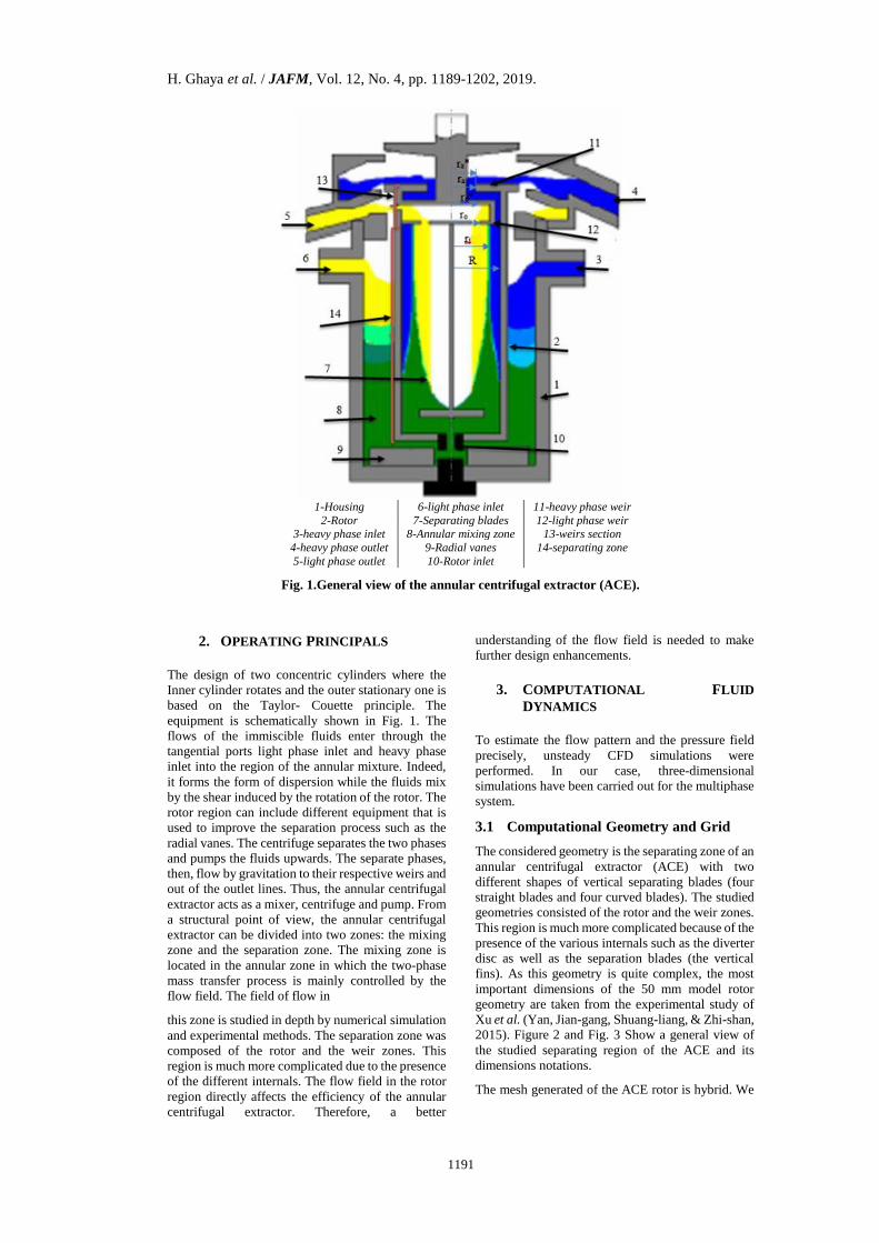
1-Housing 6-light phase inlet 11-heavy phase weir
2-Rotor 7-Separating blades 12-light phase weir 3-heavy phase inlet 8-Annular mixing zone 13-weirs section
4-heavy phase outlet 9-Radial vanes 14-separating zone
5-light phase outlet 10-Rotor inlet
Fig. 1.General view of the annular centrifugal extractor (ACE).
2. OPERATING PRINCIPALS
The design of two concentric cylinders where the
Inner cylinder rotates and the outer stationary one is
based on the Taylor- Couette principle. The
equipment is schematically shown in Fig. 1. The
flows of the immiscible fluids enter through the
tangential ports light phase inlet and heavy phase
inlet into the region of the annular mixture. Indeed,
it forms the form of dispersion while the fluids mix
by the shear induced by the rotation of the rotor. The
rotor region can include different equipment that is
used to improve the separation process such as the
radial vanes. The centrifuge separates the two phases
and pumps the fluids upwards. The separate phases,
then, flow by gravitation to their respective weirs and
out of the outlet lines. Thus, the annular centrifugal
extractor acts as a mixer, centrifuge and pump. From
a structural point of view, the annular centrifugal
extractor can be divided into two zones: the mixing
zone and the separation zone. The mixing zone is
located in the annular zone in which the two-phase
mass transfer process is mainly controlled by the
flow field. The field of flow in
this zone is studied in depth by numerical simulation
and experimental methods. The separation zone was
composed of the rotor and the weir zones. This
region is much more complicated due to the presence
of the different internals. The flow field in the rotor
region directly affects the efficiency of the annular
centrifugal extractor. Therefore, a better
understanding of the flow field is needed to make
further design enhancements.
3. COMPUTATIONAL FLUID
DYNAMICS
To estimate the flow pattern and the pressure field
precisely, unsteady CFD simulations were
performed. In our case, three-dimensional
simulations have been carried out for the multiphase
system.
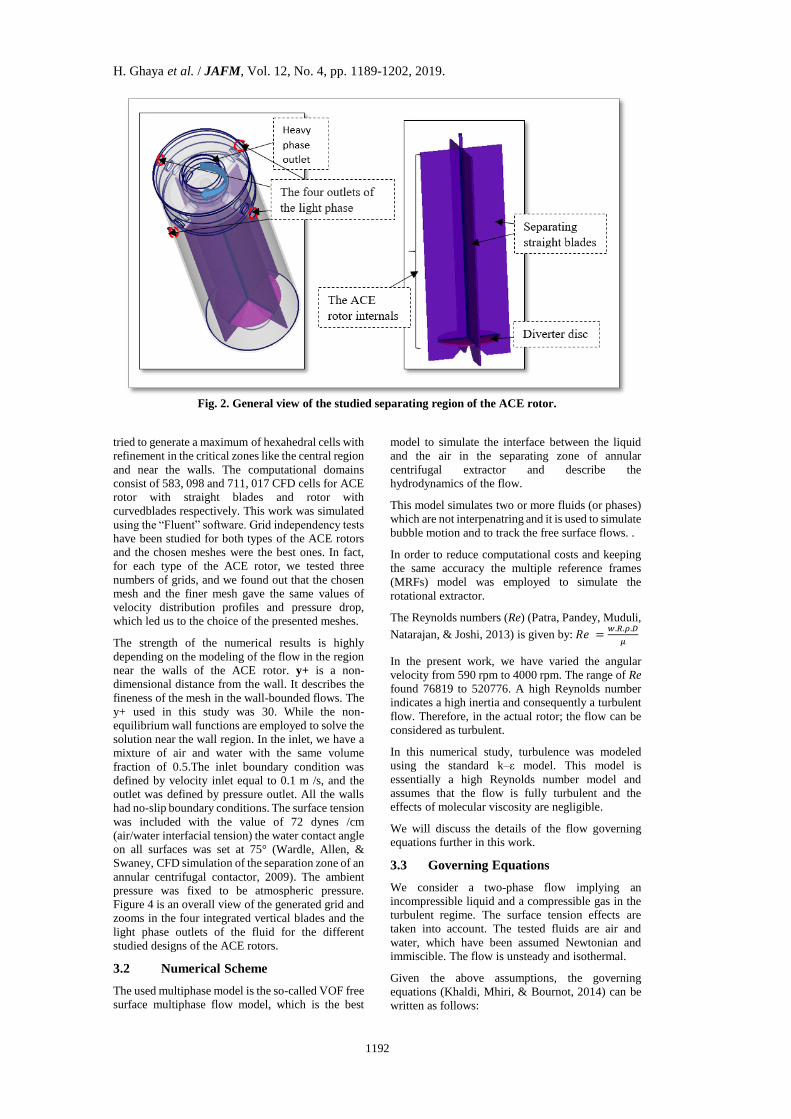
3.1 Computational Geometry and Grid
The considered geometry is the separating zone of an
annular centrifugal extractor (ACE) with two
different shapes of vertical separating blades (four
straight blades and four curved blades). The studied
geometries consisted of the rotor and the weir zones.
This region is much more complicated because of the
presence of the various internals such as the diverter
disc as well as the separation blades (the vertical
fins). As this geometry is quite complex, the most
important dimensions of the 50 mm model rotor
geometry are taken from the experimental study of
Xu et al. (Yan, Jian-gang, Shuang-liang, & Zhi-shan,
2015). Figure 2 and Fig. 3 Show a general view of
the studied separating region of the ACE and its
dimensions notations.
The mesh generated of the ACE rotor is hybrid. We
H. Ghaya et al. / JAFM, Vol. 12, No. 4, pp. 1189-1202, 2019.
1192
Fig. 2. General view of the studied separating region of the ACE rotor.
tried to generate a maximum of hexahedral cells with
refinement in the critical zones like the central region
and near the walls. The computational domains
consist of 583, 098 and 711, 017 CFD cells for ACE
rotor with straight blades and rotor with
curvedblades respectively. This work was simulated
using the “Fluent” software. Grid independency tests
have been studied for both types of the ACE rotors
and the chosen meshes were the best ones. In fact,
for each type of the ACE rotor, we tested three
numbers of grids, and we found out that the chosen
mesh and the finer mesh gave the same values of
velocity distribution profiles and pressure drop,
which led us to the choice of the presented meshes.
The strength of the numerical results is highly
depending on the modeling of the flow in the region
near the walls of the ACE rotor. y+ is a non-
dimensional distance from the wall. It describes the
fineness of the mesh in the wall-bounded flows. The
y+ used in this study was 30. While the non-
equilibrium wall functions are employed to solve the
solution near the wall region. In the inlet, we have a
mixture of air and water with the same volume
fraction of 0.5.The inlet boundary condition was
defined by velocity inlet equal to 0.1 m /s, and the
outlet was defined by pressure outlet. All the walls
had no-slip boundary conditions. The surface tension
was included with the value of 72 dynes /cm
(air/water interfacial tension) the water contact angle
on all surfaces was set at 75° (Wardle, Allen, &
Swaney, CFD simulation of the separation zone of an
annular centrifugal contactor, 2009). The ambient
pressure was fixed to be atmospheric pressure.
Figure 4 is an overall view of the generated grid and
zooms in the four integrated vertical blades and the
light phase outlets of the fluid for the different
studied designs of the ACE rotors.
3.2 Numerical Scheme
The used multiphase model is the so-called VOF free
surface multiphase flow model, which is the best
model to simulate the interface between the liquid
and the air in the separating zone of annular
centrifugal extractor and describe the
hydrodynamics of the flow.
This model simulates two or more fluids (or phases)
which are not interpenatring and it is used to simulate
bubble motion and to track the free surface flows. .
In order to reduce computational costs and keeping
the same accuracy the multiple reference frames
(MRFs) model was employed to simulate the
rotational extractor.
The Reynolds numbers (Re) (Patra, Pandey, Muduli,
Natarajan, & Joshi, 2013) is given by: 𝑅𝑒 =𝑤.𝑅.𝜌.𝐷
𝜇
In the present work, we have varied the angular
velocity from 590 rpm to 4000 rpm. The range of Re
found 76819 to 520776. A high Reynolds number
indicates a high inertia and consequently a turbulent
flow. Therefore, in the actual rotor; the flow can be
considered as turbulent.
In this numerical study, turbulence was modeled
using the standard k–ε model. This model is
essentially a high Reynolds number model and
assumes that the flow is fully turbulent and the
effects of molecular viscosity are negligible.
We will discuss the details of the flow governing
equations further in this work.
3.3 Governing Equations
We consider a two-phase flow implying an
incompressible liquid and a compressible gas in the
turbulent regime. The surface tension effects are
taken into account. The tested fluids are air and
water, which have been assumed Newtonian and
immiscible. The flow is unsteady and isothermal.
Given the above assumptions, the governing
equations (Khaldi, Mhiri, & Bournot, 2014) can be
written as follows:

H. Ghaya et al. / JAFM, Vol. 12, No. 4, pp. 1189-1202, 2019.
1193
A-A
(a) The basic geometry of the ACE rotor (b) The proposed modification of
curved blades
R R’ R*o Ra* Rd hd L a All
dimensions
are in mm 25 10 10 12 17 10 120 10
Fig. 3. Geometries and Dimensions of the studied domains (Yan, Jian-gang, Shuang-liang, & Zhi-shan,
2015).
Fig. 4. CFD grid of the studied domain and boundary conditions.
Continuity
0
i
i
u
t x
(1)
Momentum
,
iji ii i i s
i j i
u u pu g S
t x x x
(2)
Where, 𝜌 is the density, 𝑢𝑖 is the three velocity
components, 𝑝 is the pressure, and 𝜏𝑖𝑗 is the
Reynolds stress tensor.
VOF Model
To model the sharp fluid–fluid interfaces using a
finite volume approach, the VOF method is very
suitable. It has been verified that it is appropriate for
acquiring and tracking a free surface (Mokni,
Dhaouadi, Bournot, & Mhiri, 2015) (Achouri,
Mokni, Mhiri, & Bournot, 2012) (Padial-Collins,
Zhang, Zou, & Ma, 2006) (Wardle K. E., Allen,
Anderson, & Swaney, 2008) (Wardle, Allen, &

H. Ghaya et al. / JAFM, Vol. 12, No. 4, pp. 1189-1202, 2019.
1194
Swaney, CFD simulation of the separation zone of an
annular centrifugal contactor, 2009).
The tracking of the interface between the two phases
is done by a color function (phase indicator function)
that shows the fractional amount of fluid at a some
position. The interface tracking between the two
phases is done with the solution of the continuity
equation (Eq. 1) for the secondary phase (air is set as
the secondary phase in this study,). Then, the
interface is reconstructed using the geometric
reconstruction (Geo-reconstruct) method. This
method can simulate efficiently flows including the
shape and evolution of the free surface (Khaldi,
Mhiri, & Bournot, 2014). That is why this model can
simulate flows including the shape and evolution of
the free surface in the separating zone of the annular
centrifugal extractor.
This interface is calculated with the following
equation:
2 2 2 2 2
i
i
US
t x
(3)
Where 𝑆2 is the source of the phase 2 (in this study
𝑆2 is equal to zero), 𝜌2 is the density of the secondary
phase and 𝛼2 is the volume fraction of the secondary
phase (𝛼2 =V2/V).V is the total volume of fluids
(V=V1+V2), V1 is the volume of phase 1 and V2 is the
volume of phase 2.
The volume fraction of the primary phase (𝛼1=V2/V)
is deduced by the constrain:
2
1
1i
i
(4)
In the momentum Eq. (2), the interaction between the
phases is modeled by the surface tension 𝑆𝑖,𝑠.
Standard k-𝜺 Model
The standard k-ε model of turbulence is a semi
empirical model constructed on model transport
equations for the turbulence kinetic energy (k) and its
dissipation rate (ε). It is based on the Boussinesq
hypothesis, which assumes that the Reynolds stress is
proportional to the mean velocity gradient, with the
constant of proportionality being the turbulent
viscosity. This quantity is assumed by the following
equations:
2
ν t
kC
(5)
Where 𝐶𝜇is an empirical constant of the standard k–
ε model.
The model transport equation for k is derived from
the exact equation, while the model transport
equation for ε was obtained using physical reasoning
and bears little resemblance to its mathematically
exact counterpart.
The turbulence kinetic energy, k, and its rate of
dissipation, ε, are obtained from the following
transport equations (FLUENT 6.3, 2001):
k equation:
i tk
i j k j
b M
kUk kG
t x x x
G Y
(6)
ε equation:
1 3
2
2
+
i t
i j j
k b
U
t x x x
C G C Gk
Ck
(7)
In these equations, 𝐺𝑘 represents the generation of
turbulence kinetic energy due to the mean velocity
gradients. Gb is the generation of turbulence kinetic
energy due to buoyancy. YM represents the
contribution of the fluctuating dilatation in
compressible turbulence to the overall dissipation
rate. 𝐶1𝜀,𝐶2𝜀, and 𝐶3𝜀 are constants. 𝜎𝑘 and 𝜎𝜀are the
turbulent Prandtl numbers for k and ε, respectively.
MRF Model
The Multiple Reference Frame model is a steady state
approach, which can provide a reasonable model for
many applications such as the rotational flow in the
ACE equipment. The computational domain for the
numerical problem is defined with respect to the
rotating frame such that an arbitrary point in the
computational domain is located by a position vector
r from the origin of the rotating frame.
The following relation is used to transform the fluid
velocities from the stationary frame to the rotating
frame (FLUENT 6.3, 2001):
r rV V U (8)
Where
rU r (9)
Where rV is the relative velocity,
V is the absolute velocity,
rU is the “whirl” velocity (the velocity
due to the moving frame).
Solving the equations of motion in the rotating frame
introduces an additional acceleration terms in the
momentum equation.
. 0rvt
(10)
. rrv v v v pt
(11)
The Coriolis and the centripetal accelerations are
included in the momentum equation with the term
(⃗⃗ ∗ 𝑟 ).
H. Ghaya et al. / JAFM, Vol. 12, No. 4, pp. 1189-1202, 2019.
1195
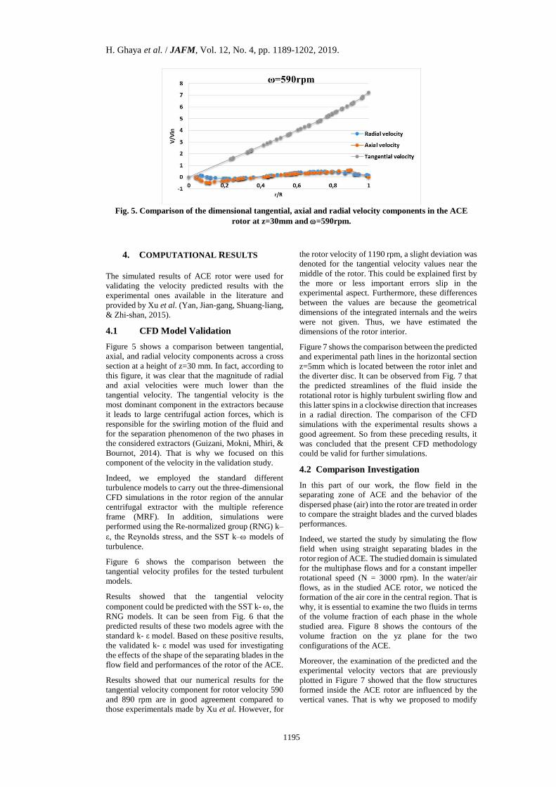
Fig. 5. Comparison of the dimensional tangential, axial and radial velocity components in the ACE
rotor at z=30mm and =590rpm.
4. COMPUTATIONAL RESULTS
The simulated results of ACE rotor were used for
validating the velocity predicted results with the
experimental ones available in the literature and
provided by Xu et al. (Yan, Jian-gang, Shuang-liang,
& Zhi-shan, 2015).
4.1 CFD Model Validation
Figure 5 shows a comparison between tangential,
axial, and radial velocity components across a cross
section at a height of z=30 mm. In fact, according to
this figure, it was clear that the magnitude of radial
and axial velocities were much lower than the
tangential velocity. The tangential velocity is the
most dominant component in the extractors because
it leads to large centrifugal action forces, which is
responsible for the swirling motion of the fluid and
for the separation phenomenon of the two phases in
the considered extractors (Guizani, Mokni, Mhiri, &
Bournot, 2014). That is why we focused on this
component of the velocity in the validation study.
Indeed, we employed the standard different
turbulence models to carry out the three-dimensional
CFD simulations in the rotor region of the annular
centrifugal extractor with the multiple reference
frame (MRF). In addition, simulations were
performed using the Re-normalized group (RNG) k–
ε, the Reynolds stress, and the SST k– models of
turbulence.
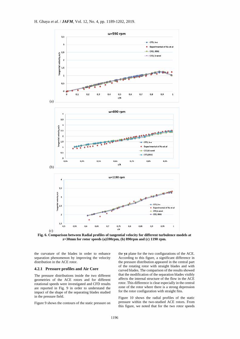
Figure 6 shows the comparison between the
tangential velocity profiles for the tested turbulent
models.
Results showed that the tangential velocity
component could be predicted with the SST k- , the
RNG models. It can be seen from Fig. 6 that the
predicted results of these two models agree with the
standard k- ε model. Based on these positive results,
the validated k- ε model was used for investigating
the effects of the shape of the separating blades in the
flow field and performances of the rotor of the ACE.
Results showed that our numerical results for the
tangential velocity component for rotor velocity 590
and 890 rpm are in good agreement compared to
those experimentals made by Xu et al. However, for
the rotor velocity of 1190 rpm, a slight deviation was
denoted for the tangential velocity values near the
middle of the rotor. This could be explained first by
the more or less important errors slip in the
experimental aspect. Furthermore, these differences
between the values are because the geometrical
dimensions of the integrated internals and the weirs
were not given. Thus, we have estimated the
dimensions of the rotor interior.
Figure 7 shows the comparison between the predicted
and experimental path lines in the horizontal section
z=5mm which is located between the rotor inlet and
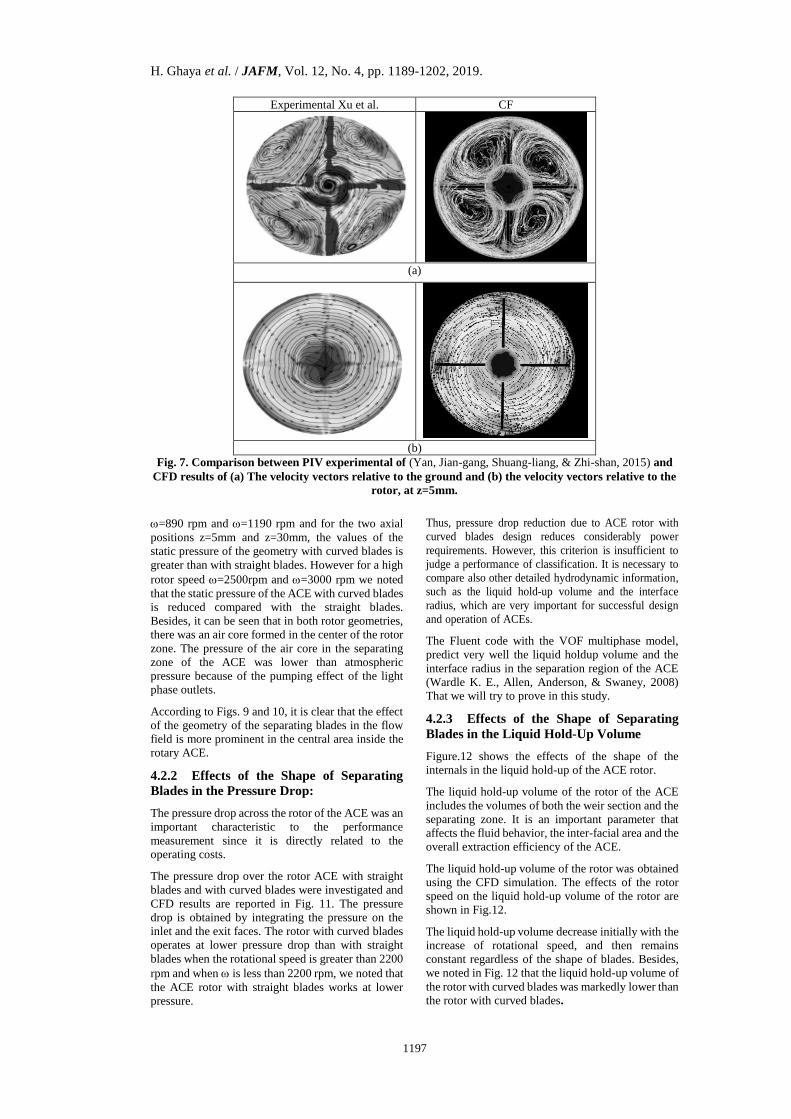
the diverter disc. It can be observed from Fig. 7 that
the predicted streamlines of the fluid inside the
rotational rotor is highly turbulent swirling flow and
this latter spins in a clockwise direction that increases
in a radial direction. The comparison of the CFD
simulations with the experimental results shows a
good agreement. So from these preceding results, it
was concluded that the present CFD methodology
could be valid for further simulations.
4.2 Comparison Investigation
In this part of our work, the flow field in the
separating zone of ACE and the behavior of the
dispersed phase (air) into the rotor are treated in order
to compare the straight blades and the curved blades
performances.
Indeed, we started the study by simulating the flow
field when using straight separating blades in the
rotor region of ACE. The studied domain is simulated
for the multiphase flows and for a constant impeller
rotational speed (N = 3000 rpm). In the water/air
flows, as in the studied ACE rotor, we noticed the
formation of the air core in the central region. That is
why, it is essential to examine the two fluids in terms
of the volume fraction of each phase in the whole
studied area. Figure 8 shows the contours of the
volume fraction on the yz plane for the two
configurations of the ACE.
Moreover, the examination of the predicted and the
experimental velocity vectors that are previously
plotted in Figure 7 showed that the flow structures
formed inside the ACE rotor are influenced by the
vertical vanes. That is why we proposed to modify
H. Ghaya et al. / JAFM, Vol. 12, No. 4, pp. 1189-1202, 2019.
1196
(a)
(b)
(c)
Fig. 6. Comparison between Radial profiles of tangential velocity for different turbulence models at
z=30mm for rotor speeds (a)590rpm, (b) 890rpm and (c) 1190 rpm.
the curvature of the blades in order to enhance
separation phenomenon by improving the velocity
distribution in the ACE rotor.
4.2.1 Pressure profiles and Air Core
The pressure distributions inside the two different
geometries of the ACE rotors and for different
rotational speeds were investigated and CFD results
are reported in Fig. 9 in order to understand the
impact of the shape of the separating blades studied
in the pressure field.
Figure 9 shows the contours of the static pressure on
the yz plane for the two configurations of the ACE.
According to this figure, a significant difference in
the pressure distribution appeared in the central part
of the rotating rotor with straight blades and with
curved blades. The comparison of the results showed
that the modification of the separation blades visibly
affects the internal structure of the flow in the ACE
rotor. This difference is clear especially in the central
zone of the rotor where there is a strong depression
for the rotor configuration with straight fins.
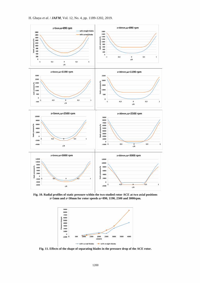
Figure 10 shows the radial profiles of the static
pressure within the two-studied ACE rotors. From
this figure, we noted that for the two rotor speeds
H. Ghaya et al. / JAFM, Vol. 12, No. 4, pp. 1189-1202, 2019.
1197
Experimental Xu et al. CF
(a)
(b)
Fig. 7. Comparison between PIV experimental of (Yan, Jian-gang, Shuang-liang, & Zhi-shan, 2015) and
CFD results of (a) The velocity vectors relative to the ground and (b) the velocity vectors relative to the
rotor, at z=5mm.
=890 rpm and =1190 rpm and for the two axial
positions z=5mm and z=30mm, the values of the
static pressure of the geometry with curved blades is
greater than with straight blades. However for a high
rotor speed =2500rpm and =3000 rpm we noted
that the static pressure of the ACE with curved blades
is reduced compared with the straight blades.
Besides, it can be seen that in both rotor geometries,
there was an air core formed in the center of the rotor
zone. The pressure of the air core in the separating
zone of the ACE was lower than atmospheric
pressure because of the pumping effect of the light
phase outlets.
According to Figs. 9 and 10, it is clear that the effect
of the geometry of the separating blades in the flow
field is more prominent in the central area inside the
rotary ACE.
4.2.2 Effects of the Shape of Separating
Blades in the Pressure Drop:
The pressure drop across the rotor of the ACE was an
important characteristic to the performance
measurement since it is directly related to the
operating costs.
The pressure drop over the rotor ACE with straight
blades and with curved blades were investigated and
CFD results are reported in Fig. 11. The pressure
drop is obtained by integrating the pressure on the
inlet and the exit faces. The rotor with curved blades
operates at lower pressure drop than with straight
blades when the rotational speed is greater than 2200
rpm and when is less than 2200 rpm, we noted that
the ACE rotor with straight blades works at lower
pressure.
Thus, pressure drop reduction due to ACE rotor with
curved blades design reduces considerably power
requirements. However, this criterion is insufficient to
judge a performance of classification. It is necessary to
compare also other detailed hydrodynamic information,
such as the liquid hold-up volume and the interface
radius, which are very important for successful design
and operation of ACEs.
The Fluent code with the VOF multiphase model,
predict very well the liquid holdup volume and the
interface radius in the separation region of the ACE
(Wardle K. E., Allen, Anderson, & Swaney, 2008)
That we will try to prove in this study.
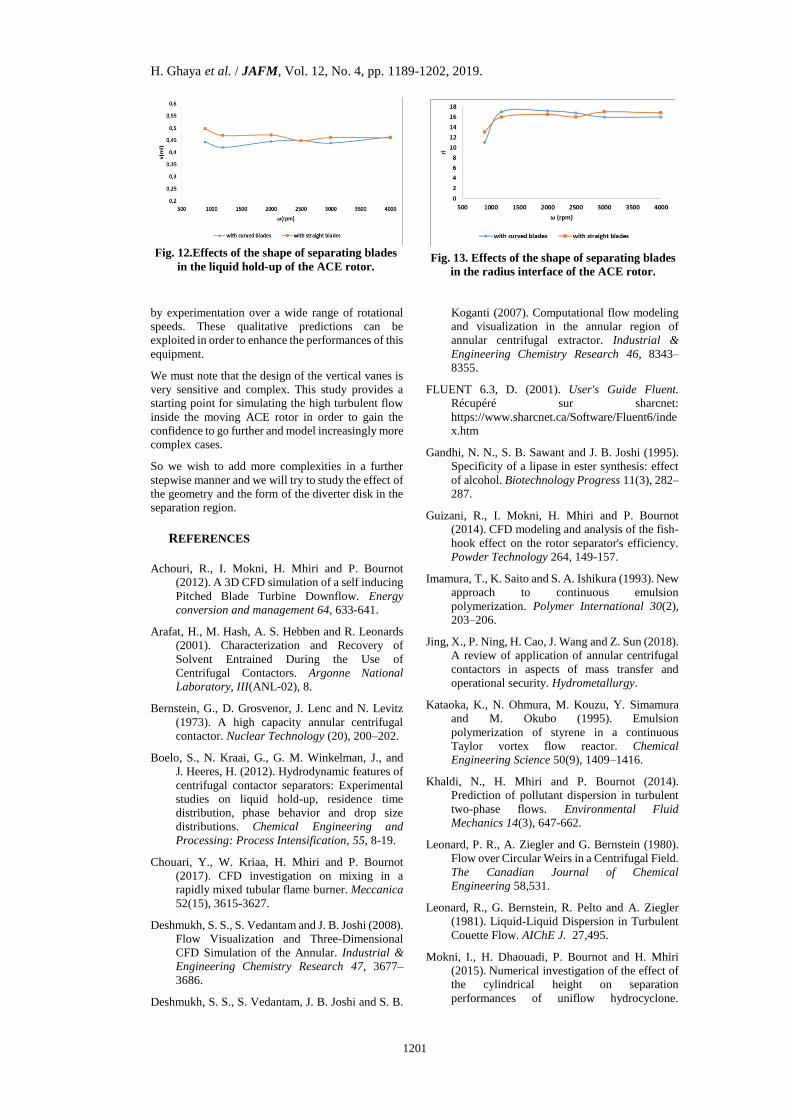
4.2.3 Effects of the Shape of Separating
Blades in the Liquid Hold-Up Volume
Figure.12 shows the effects of the shape of the
internals in the liquid hold-up of the ACE rotor.
The liquid hold-up volume of the rotor of the ACE
includes the volumes of both the weir section and the
separating zone. It is an important parameter that
affects the fluid behavior, the inter-facial area and the
overall extraction efficiency of the ACE.
The liquid hold-up volume of the rotor was obtained
using the CFD simulation. The effects of the rotor
speed on the liquid hold-up volume of the rotor are
shown in Fig.12.
The liquid hold-up volume decrease initially with the
increase of rotational speed, and then remains
constant regardless of the shape of blades. Besides,
we noted in Fig. 12 that the liquid hold-up volume of
the rotor with curved blades was markedly lower than
the rotor with curved blades.
H. Ghaya et al. / JAFM, Vol. 12, No. 4, pp. 1189-1202, 2019.
1198
(a) (b)
(c)
Fig. 8. Contours of the volume fraction of water in the permanent regime within the two studied rotor
ACE, (a) rotor with straight blades, (b) rotor with curved blades, (c) Air/water interfaces for different
heights z=90mm and z=30mm.
4.2.4 Effects of the Shape of Separating
Blades in the Interface Radius:
Figure 13 shows the effects of the geometry of
separating blades in the radius interface of the ACE
rotor.
The light (air)-heavy phase (water) interface is
formed as a vertical cylindrical surface. The effect of
rotor speed () on the interface radius is shown in
Fig. 13. The values of ri increases initially with the
increase of () and demure constant. We noted also,
that the values of ri for the rotor with curved blades
is greater than the geometry with straight vanes in the
range of = [1000-2200].
5. CONCLUSION
This study has presented the results of CFD
calculations of the flow in the settling region of an
annular centrifugal contactor.
The tangential velocity at various rotation speeds
were compared with experimental results. A good
agreement between the CFD predictions and the
experimental measurements was obtained. The
results proved that the k-ε turbulence model could
describe accurately the flow pattern in the separation
zone of the extractor in terms of streamlines, static
pressure distribution and velocity profiles.
The separation phenomenon in an ACE rotor has
been investigated by CFD analysis. Standard k-ε and
volume of fluid models have been used to model the
turbulence nature and the multiphase flow of the
ACE rotor.
The CFD results for a range of rotor speeds were
performed to characterize the flow of water in the
settling region of the ACE using two different
separating blades geometries.

H. Ghaya et al. / JAFM, Vol. 12, No. 4, pp. 1189-1202, 2019.
1199
Rotor speed rpm Separating zone with straight blades Separating zone with curved blades
=890
=1190
=2500
Fig. 9. Effects of the shape of separating blades and the rotor velocity on the pressure field inside the
ACE rotor.
It was found that the flow inside the rotor is turbulent
forced vortex flow for the two types of the ACE
rotor. Besides, we noticed that the static pressure for
both geometries is highest near the wall and decrease
gradually with respect to the radial distance from the
wall to the center, which provides the separation of
the heavy phase fluid to be separated from the light
phase fluid in order to be derived to the appropriate
outlet. In addition, we noticed that the geometry of
the separating blades in the flow field is more
prominent in the central area inside the rotary ACE.
However, the central region in the rotor is highly
influenced with the geometry of internals, which
prevents the increase of the static pressure in the axis
of rotation and the central vortex.
Besides, the predicted pressure drop proved that the
geometry of the ACE rotor with curved blades leads
to a lower values of pressure drop which is related to
the power consumption of energy for rotor speeds
superior to =2200 rpm. Thus, the pressure drop to
ACE rotor with curved blades design reduces
considerably power requirements geometry of the
vertical separating blades.
In addition, it was found that curved blades has a
significant impact on the liquid hold-up, in the
interface radius and on the general flow in the
separating zone.
It is to be noted that the CFD tools provide details on
the entire flow field inside the ACE rotor not possible
H. Ghaya et al. / JAFM, Vol. 12, No. 4, pp. 1189-1202, 2019.
1200
Fig. 10. Radial profiles of static pressure within the two studied rotor ACE at two axial positions
z=5mm and z=30mm for rotor speeds =890, 1190, 2500 and 3000rpm.
Fig. 11. Effects of the shape of separating blades in the pressure drop of the ACE rotor.
H. Ghaya et al. / JAFM, Vol. 12, No. 4, pp. 1189-1202, 2019.
1201
Fig. 12.Effects of the shape of separating blades
in the liquid hold-up of the ACE rotor.
Fig. 13. Effects of the shape of separating blades
in the radius interface of the ACE rotor.
by experimentation over a wide range of rotational
speeds. These qualitative predictions can be
exploited in order to enhance the performances of this
equipment.
We must note that the design of the vertical vanes is
very sensitive and complex. This study provides a
starting point for simulating the high turbulent flow
inside the moving ACE rotor in order to gain the
confidence to go further and model increasingly more
complex cases.
So we wish to add more complexities in a further
stepwise manner and we will try to study the effect of
the geometry and the form of the diverter disk in the
separation region.
REFERENCES
Achouri, R., I. Mokni, H. Mhiri and P. Bournot
(2012). A 3D CFD simulation of a self inducing
Pitched Blade Turbine Downflow. Energy
conversion and management 64, 633-641.
Arafat, H., M. Hash, A. S. Hebben and R. Leonards
(2001). Characterization and Recovery of
Solvent Entrained During the Use of
Centrifugal Contactors. Argonne National
Laboratory, III(ANL-02), 8.
Bernstein, G., D. Grosvenor, J. Lenc and N. Levitz
(1973). A high capacity annular centrifugal
contactor. Nuclear Technology (20), 200–202.
Boelo, S., N. Kraai, G., G. M. Winkelman, J., and
J. Heeres, H. (2012). Hydrodynamic features of
centrifugal contactor separators: Experimental
studies on liquid hold-up, residence time
distribution, phase behavior and drop size
distributions. Chemical Engineering and
Processing: Process Intensification, 55, 8-19.
Chouari, Y., W. Kriaa, H. Mhiri and P. Bournot
(2017). CFD investigation on mixing in a
rapidly mixed tubular flame burner. Meccanica
52(15), 3615-3627.
Deshmukh, S. S., S. Vedantam and J. B. Joshi (2008).
Flow Visualization and Three-Dimensional
CFD Simulation of the Annular. Industrial &
Engineering Chemistry Research 47, 3677–
3686.
Deshmukh, S. S., S. Vedantam, J. B. Joshi and S. B.
Koganti (2007). Computational flow modeling
and visualization in the annular region of
annular centrifugal extractor. Industrial &
Engineering Chemistry Research 46, 8343–
8355.
FLUENT 6.3, D. (2001). User's Guide Fluent.
Récupéré sur sharcnet:
https://www.sharcnet.ca/Software/Fluent6/inde
x.htm
Gandhi, N. N., S. B. Sawant and J. B. Joshi (1995).
Specificity of a lipase in ester synthesis: effect
of alcohol. Biotechnology Progress 11(3), 282–
287.
Guizani, R., I. Mokni, H. Mhiri and P. Bournot
(2014). CFD modeling and analysis of the fish-
hook effect on the rotor separator's efficiency.
Powder Technology 264, 149-157.
Imamura, T., K. Saito and S. A. Ishikura (1993). New
approach to continuous emulsion
polymerization. Polymer International 30(2),
203–206.
Jing, X., P. Ning, H. Cao, J. Wang and Z. Sun (2018).
A review of application of annular centrifugal
contactors in aspects of mass transfer and
operational security. Hydrometallurgy.
Kataoka, K., N. Ohmura, M. Kouzu, Y. Simamura
and M. Okubo (1995). Emulsion
polymerization of styrene in a continuous
Taylor vortex flow reactor. Chemical
Engineering Science 50(9), 1409–1416.
Khaldi, N., H. Mhiri and P. Bournot (2014).
Prediction of pollutant dispersion in turbulent
two-phase flows. Environmental Fluid
Mechanics 14(3), 647-662.
Leonard, P. R., A. Ziegler and G. Bernstein (1980).
Flow over Circular Weirs in a Centrifugal Field.
The Canadian Journal of Chemical
Engineering 58,531.
Leonard, R., G. Bernstein, R. Pelto and A. Ziegler
(1981). Liquid-Liquid Dispersion in Turbulent
Couette Flow. AIChE J. 27,495.
Mokni, I., H. Dhaouadi, P. Bournot and H. Mhiri
(2015). Numerical investigation of the effect of
the cylindrical height on separation
performances of uniflow hydrocyclone.

H. Ghaya et al. / JAFM, Vol. 12, No. 4, pp. 1189-1202, 2019.
1202
Chemical Engineering Science(122), 500-513.
Ogihara, N., G. Matsuda, T.Yanagawa, N. Ogata, K.
Fujita and M. Nomura (1995). Continuous
synthesis of monodispersed silica particles
using Couette-Taylor vortex flow. Journal of
the Ceramic Society of Japan 103, 151–154.
Padial-Collins, N. T., D. Z. Zhang, Q. Zou and X. Ma
(2006). Centrifugal contactors: Separation of an
aqueous and an organic stream in the rotor zone.
Separation Science and Technology 41, 1001–
1023.
Patra, J., N. K. Pandey, U. K. Muduli, R. Natarajan
and J. B. Joshi (2013). Hydrodynamic study of
flow in the rotor region of annular centrifugal
contactors using CFD simulation. Chemical
Engineering Communications 200(4), 471-493.
Sathe, M. J., S. S. Deshmukh, J. B. Joshi and S. B.
Koganti (2010). Computational fluid dynamics
simulation and experimental investigation:
study of two-phase liquid-liquid flow in a
vertical Taylor-Couette contactor. Industrial &
Engineering Chemistry Research 49(1), 14–28.
Shaowei, L., D. Wuhua, C. Jing and W. Jianchen
(2012). CFD Simulation of Gas-Liquid-Liquid
Three-Phase Flow in an Annular Centrifugal
Contactor. Industrial & Engineering Chemistry
Research 51, 11245-11253.
Wardle, K. E., T. R. Allen and R. Swaney (2009).
CFD simulation of the separation zone of an
annular centrifugal contactor. Separation
Science and Technology 44(3), 517-542.
Wardle, K. E., T. R. Allen, M. H. Anderson and R. E.
Swaney (2008). Free surface flow in the mixing
zone of an annular centrifugal contactor. AIChE
Journal 54(1), 74-85.
Wardle, K., T. Allen, M. Anderson and R. Swaney
(2009). Analysis of the effect of mixing vane
geometry on the flow in an annular centrifugal
contactor. AIChE J., In press.
Yan, X., W. Jian-gang, Z. Shuang-liang and B. Zhi-
shan (2015). PIV experimental study on the
flow field in the rotor zone of an annular
centrifugal contactor. Chemical engineering
research and design 94, 691–701.
Zhou, J., W. Duan, X. Zhou and C. Zhang (2007).
Application of annular centrifugal contactors in
the extraction flowsheet for producing high
purity yttrium. Hydrometallurgy 85(2-4), 154-
162.