Embed Size (px)
Citation preview
1
The Effect of Coordinate System Variation on In Vivo Patellofemoral Kinematic Measures
Angela E. Kedgley, PhDa,1
Emily J. McWalter, PhDb,2
David R Wilson, DPhila,c
aDepartment of Orthopaedics
University of British Columbia
3114 - 910 West 10th Avenue
Vancouver, BC V5Z 1M9 Canada
bDepartment of Mechanical Engineering
University of British Columbia
2054-6250 Applied Science Lane,
Vancouver, BC V6T 1Z4 Canada
cCentre for Hip Health and Mobility
Vancouver Coastal Health Research Institute
7/F, 2635 Laurel Street
Robert H.N. Ho Research Centre
Vancouver, BC V5Z 1M9 Canada
1Present address: Department of Bioengineering
Imperial College London
South Kensington Campus
London, SW7 2AZ United Kingdom
2Present address: Department of Radiology
The Lucas Center for MR Spectroscopy and Imaging
P064-1201 Welch Road
Stanford, CA 94305-5488 United States of America
Correspondence:
Angela E. Kedgley
Department of Bioengineering
Imperial College London
South Kensington Campus
London, SW7 2AZ
United Kingdom
Phone: 011 44 (+0) 207 594 0747
Email: [email protected]
2
Abstract
Background: The use of different coordinate system definitions for the patella leads to
difficulties in comparing kinematic results between studies. The purpose of this work
was to establish the effect of using a range of coordinate system definitions to quantify
patellar kinematics. Additionally, intra- and inter-investigator repeatabilities of the
digitization of anatomic landmarks on the patella were determined.
Methods: Four different patellar coordinate system definitions were applied using
digitisations in two and three dimensions and a single femoral coordinate system was
used for comparison. Intra-investigator variability was established by having one
investigator digitize the patellar landmarks of three subjects on five separate occasions.
Inter-investigator variability was quantified by having five participants digitize the same
landmarks on the same three subjects. Patellofemoral kinematics were quantified for ten
subjects, at six angles of tibiofemoral flexion, using MRI.
Results: As a result of changes in the patellar coordinate system, differences of up to
11.5° in flexion, 5.0° in spin, and 27.3° in tilt were observed in the resultant rotations for
the same motion, illustrating the importance of standardizing the coordinate system
definition.
Conclusions: To minimize errors due to variability while still maintaining
physiologically sensible kinematic angles, a coordinate system based upon an
intermediate flexion axis between the most medial and lateral points on the patella, and a

3
superiorly-directed long axis located between the most proximal and distal points on the
patella, with an origin at the centre of the most proximal, distal, medial, and lateral points
on the patella is recommended.
Keywords: coordinate system; patella; landmarks; patellofemoral kinematics
4
1. Introduction
Patellar kinematics have been measured in a wide range of studies of normal,
pathological and treated knees. An essential step in describing kinematics is defining a
coordinate system at the joint, but there is currently no standard definition of a coordinate
system for the patella. This makes comparing results across the literature difficult, if not 5
impossible [1]. The most widely used method of assigning coordinate systems is to select
anatomical landmarks that allow the creation of an origin point, a flexion axis, and a long
axis. A third axis is determined from the cross product of the long and flexion axes, and
an orthogonal flexion axis is then found by taking the cross product of this third axis with
the long axis. An orthogonal coordinate system is consequently formed by the second 10
flexion axis, the long axis and the third axis. Many combinations of landmarks have been
used to assign coordinate systems to the femur and patella (Table 1), and these are likely
responsible, in part, for the variability in patellofemoral kinematics that is seen in the
literature.
Alternatives to anatomical coordinate system definitions include fitting a 15
bounding box [22,23] and the recently proposed method of an automated algorithm that
makes use of the posterior ridge of the patella [20]. Although these two methods will
result in repeatable coordinate frame definitions, their automated nature means that they
may not always align with patellar anatomy. In particular, the use of a bounding box is
affected by the orientation of the knee in the scanner. Obviously, other confounding 20
factors include natural and pathological anatomic variability of the patella and femur
[24,25]. However, in order to determine the effects of pathologies a consistent means of
5
quantifying changes must be established and this requires a consistent way to quantify
“normal” anatomy and kinematics.
There have been several attempts to quantify errors in coordinate system creation 25
and to standardize aspects of its application, but no standard definition has been proposed
and implemented by the biomechanics community. Bull et al. investigated various
methods of describing patellofemoral motion and also compared the kinematic outcomes
of using two different femoral flexion and long axis definitions [1]. However, the effect
of the variation of the patellar coordinate system was not investigated. Several 30
investigators have quantified the repeatability [2,12,26-28] and sensitivity [11] of the
creation of their particular patellar coordinate systems. Katchburian et al. [29] conducted
a thorough review of patellar kinematics and recommended the coordinate system
described by Lafortune [30] as being the ‘most useful’, possibly because it follows the
method suggested by Grood and Suntay [31]. However, this is the only direct 35
comparison of a range of coordinate systems in the literature to date.
Within the clinical community several studies have examined inter- and intra-
observer variability of patellar measures such as sulcus angle, congruence angle, patellar
height, patellar axis, lateral patellofemoral angle, lateral patellar tilt [32-34].
Unfortunately, these measures do not describe three-dimensional kinematics, and 40
therefore cannot fully characterize patellar motion.
Selection of appropriate landmarks that allow for coordinate system creation is
important. Landmarks should be defined without ambiguity and it should be possible to
digitize them repeatably. The landmarks for an in vitro study, which may involve
disarticulation of the joint, may not be appropriate for an in vivo study. The use of 45

6
palpation in vivo may yield different results to those obtained from an imaging study.
Additionally, imaging modalities, such as computed tomography (CT) [35,36] and
magnetic resonance imaging (MRI) scans [8,18,19,37-39] are increasingly being
employed to measure patellar kinematics. The locations of the required landmarks may
be digitized from these scans using two- or three-dimensional imaging techniques. Two 50
dimensional techniques are prone to projection errors due to the alignment of the subject
within the imaging device [40], and therefore it would seem that three-dimensional
measures would be preferable.
The selection of a preferred coordinate system should provide, at the very least, a
repeatable way to quantify kinematics, allowing the same reference frames to be 55
employed for a range of subjects, thereby facilitating comparisons between them. In
addition, as mentioned by Wu et al., clinically relevant kinematic results, which can be
used to interpret the movements of the bones in a meaningful way, are preferable [41].
Therefore, in this study the research questions were:
What are the intra- and inter-investigator repeatabilities of the digitization of 60
anatomic landmarks on the patella from MRI images?
What are the effects of varying the patellar coordinate system definition on the
resulting in vivo three-dimensional patellofemoral kinematics?
Is there one patellar coordinate system definition that is preferable over all
others for use with imaging techniques? 65
2. Methods
2.1 Subjects and imaging
7
Ten normal subjects with no history of knee pain, injury, osteoarthritis, surgery, or
contraindication to MRI were recruited to participate in this study (4 female, 6 male, 34 ±
6 yrs, 70.8 ± 15.8 kg). Institutional ethics board approval was obtained and each subject 70
provided informed consent. A initial MRI scan was acquired in the sagittal plane with
the subject’s knee in a relaxed position using a 3T MRI scanner (Intera, Phillips, Best,
The Netherlands) and the following parameters: 0.586mm in-plane resolution, 300mm
field of view, 2mm slice separation, 512 x 512 matrix size, 360ms repetition time, 10.0ms
echo time, 90° flip angle, knee MRI coil. Subject-specific bone models of the femur and 75
patella were created from this scan [42]. Six additional MRI scans were then acquired in
the sagittal plane with the following parameters: 1.25mm in-plane resolution, 320mm
field of view, 7mm slice separation, 256 x 256 matrix size, 307ms repetition time, 6.2ms
echo time, 90° flip angle, body MRI coil. For each scan the subject’s knee was placed in
one of six flexion angles, ranging from 0° to 50°, in increments of 10°, with a load of 80
15% bodyweight applied to the foot [42]. To determine the joint angles from the loaded
scans, the bone models were registered to the images using an Iterative Closest Points
algorithm implemented in Matlab (The MathWorks, Natick, MA, USA) [42].
2.2 Landmark digitization
Digitization of landmarks from the high-resolution scans was performed using 85
Analyze 8.1 (Analyze Direct Inc, Overland Park, KS, USA) image processing software.
The locations of seven landmarks on the bony surface of the patella were digitized and
the locations of three additional points were calculated (Table 2, Fig. 1). Landmarks
were selected only if they were applicable to an in vivo analysis (i.e. they could be
determined through palpation and/or imaging techniques). The insertions of the 90
8
quadriceps and patellar tendons were not included for this reason, although they have
been used in the literature. Possible origin locations were selected from among those that
were previously used in the literature for being well defined, applicable to an in vivo
analysis, and based solely on patellar landmarks.
The position of each digitized landmark was identified by a single point selection. 95
Intra-investigator variability was established by having one investigator digitize the
patellar landmarks of three subjects on five separate occasions. Inter-investigator
variability was quantified by having four other participants digitize the same landmarks
on the same three subjects. All participants were given the same set of written
instructions to follow and were asked to record all intermediate data, such as the 100
calculation of a mid-slice location. The variability of the digitized landmarks and
calculated locations was represented by the mean of the three radii defining the smallest
ellipsoid that contained all of the points with a tolerance of 1x10⁻⁶
mm [43].
2.3 Coordinate system variation
To determine how differences in the patellar coordinate system axes affect three-105
dimensional kinematics, four different patellar axis definitions were applied to each
subject. The landmarks that were selected as the basis of the flexion and long axes for
each coordinate system are listed in Table 3. For each definition the cross product of the
long axis and the flexion axis yielded the third, anteriorly-pointing axis. The cross
product was again applied to the third axis and the long axis to obtain an orthogonal 110
flexion axis. Positive directions for the right-handed coordinate systems were proximal,
lateral, and anterior, respectively. Rotations about the three axes were found using a
modified Joint Coordinate System convention [8,44]. The origin was the same for all
9
patellar coordinate systems and was based upon landmarks chosen according to the
repeatability results of the previous section. Each coordinate system was applied to both 115
the two- and three-dimensional digitizations, resulting in a total of eight coordinate
system trials.
In order to facilitate the comparison of the patellar coordinate systems, a single
femoral coordinate system was created for each subject, with a flexion axis between the
most posterior points on the femoral condyles, and the long axis from the centre of the 120
femur at the midshaft to the centre of the shaft above the condyles. Again, two cross
products were applied to obtain an orthogonal right-handed coordinate system, the first
between the long and flexion axes, and the second between the third and long axes. The
origin for the femoral coordinate system was the most proximal point of the intercondylar
notch [15]. 125
2.4 Landmark and coordinate system comparisons
The repeatabilities of intra- and inter-investigator digitizations were compared by
ranking the means of the three radii defining the smallest ellipsoid that contained all of
the selections of a particular landmark [43]. The repeatabilities of potential locations for
the patellar coordinate system origin were ranked in a similar way. Variability of the 130
kinematic quantities was defined as the standard deviations of flexion, spin, and tilt over
all six knee flexion angles for the three repeatedly measured subjects. To establish the
effect of choosing a different coordinate system on the kinematic outcomes the mean
absolute differences between resultant rotations were calculated for the full ranges of
motion of all ten subjects. In addition, we tested the hypothesis that coordinate system 135
10
definition changed joint kinematics using Wilcoxon signed rank tests and Spearman rank
correlation coefficients (SRCCs). Significant differences were defined as p < 0.05.
3. Results
3.1 Landmark digitization
The patellar landmark with the least intra- and inter-investigator variability was 140
the most distal point in both two (Dist-2) and three dimensions (Dist-3; Table 2). In
terms of inter-investigator variability only, in three dimensions the second and third least
variable landmarks were the most lateral point on the patella (Lat-3) and the most distal
point on the patellar spine (Dist.Spine-3). The landmark with the most intra- and inter-
investigator variability in three dimensions was the most posterior point on the patella 145
(Post-3). Based upon these results, when digitizations were performed in three
dimensions, it would be expected that the first coordinate system definition (3D-1) would
be the most repeatable. In two dimensions the second and third least variable landmarks
were the most distal (Dist.Spine-2) and most proximal (Prox.Spine-2) points on the
patellar spine. 150
The origin location with the least intra- and inter-investigator variability in three
dimensions was the centre of the most proximal, distal, medial, and lateral points (Centre-
3; Table 2). In two dimensions, the most repeatable point was the midpoint of the most
proximal and distal points of the patellar spine (Prox.Dist-2).
3.2 Coordinate system variation 155
As anticipated from the results of the landmark digitizations, in three dimensions
3D-1 produced the least variable results overall (Fig. 2). In two dimensions 2D-1 and
2D-2 had the least variability in kinematic output. A representative set of coordinate
11
systems are shown in Figure 3. The greatest differences in mean kinematic angles were
between coordinate systems 3D-2 and 3D-3 with average differences of 11.5° in flexion, 160
5.0° in spin, and 27.3° in tilt (Table 4); however, statistically significant differences were
found between many of the coordinate systems. The only pair with no significant
differences between two and three dimensions was 2D-2 and 3D-2. Despite this, SRCCs
amongst coordinate systems in two or three dimensions revealed excellent agreement
between all coordinate system definitions in flexion in both (SRCC ≥ 0.970), as well as in 165
spin and tilt in two dimensions (SRCC ≥ 0.881 and 0.903 respectively). Low agreement
was found in spin and tilt in three dimensions (SRCC ≥ 0.445 and ≥ 0.622 respectively).
SRCCs between coordinate systems in two and three dimensions using the same
landmarks showed the highest agreement between 2D-1 and 3D-1 (SRCC = 0.996 in
flexion, 0.792 in spin, and 0.920 in tilt). 170
4. Discussion
We assessed the effects of varying the patellar coordinate system definition on
patellofemoral kinematic quantities and the intra- and inter-investigator repeatabilities of
the digitization of anatomic landmarks on the patella from MRI images because a
standard coordinate system for the patella has yet to be proposed or adopted. Our results 175
show clearly that the choice of anatomic landmarks can result in large changes in the
resultant patellar rotations with respect to the femur. It is therefore not surprising that
results have varied greatly in the literature, even in studies of healthy individuals [29]. It
is likely that even more variation would be observed in pathological joints, where
landmarks may not have the same relative positions; this makes it all the more important 180
to standardize the patellar coordinate system in studies of pathological joints..
12
In general, the intra- and inter-investigator repeatabilities of landmark digitization
were comparable to previous studies. The average radii of the points selected by five
investigators were on the same order as, and generally less than, those found by a similar
study that examined landmarks of the scapula [43]. These results are also on the same 185
order as those of Ahmed et al. and Belvedere et al., who quantified the variability of their
respective patellar coordinate system definitions in cadaveric specimens [2,12]. As
would be expected, intra-observer repeatability was better than inter-observer
repeatability, so if possible a single investigator should perform all digitization for a
given study. 190
The choice of coordinate system had a substantial effect on three-dimensional
patellar kinematic quantities and their repeatability. The differences in kinematic
quantities between coordinate systems were much larger than anticipated, with the
greatest differences observed in tilt. The differences were clearly associated with
differences in the landmarks used to define their axes. For example, the patellofemoral 195
flexion angle was dictated by the landmarks that were selected to define the long axis,
and patellofemoral tilt was affected by flexion axis definition. These correspondences
were also found by Morton et al. in their probabilistic analysis examining the sensitivity
of patellofemoral kinematics to anatomical landmark locations in a cadaver model [28].
The large differences emphasize the importance of standardizing the patellar coordinate 200
system.
The most suitable coordinate system for any given application is generally the one
that yields the least variability, and the choice will be dictated by whether the
measurements are made in two or three dimensions. For three dimensional
13
measurements, 3D-1 is recommended, to minimize confounding errors. To maintain 205
consistency, the use of 2D-1 is similarly recommended when digitizations are to be
performed in two dimensions. The differences between the resultant kinematic angles
from these two coordinate system definitions in two and three dimensions are small and
their agreement is high, as demonstrated by the SRCCs. The origin location should also
be the point with the least variability, namely Centre-3 in three dimensions and Centre-2-210
3 in two dimensions.
The use of a single digitizing modality may be viewed as a limitation; however,
the aim of this study was not to compare software packages, and these results are
considered to be representative of what would be expected in an MRI-based study. In
addition, the use of mathematical models to determine coordinate systems automatically 215
was not addressed. Due to their automated nature, it is expected that the repeatability
would be high; however, as noted previously, in particular when using a bounding box
method the alignment of the axes are affected by the alignment of the subject within the
scanner. It has been noted that certain joint pathologies may alter the shape of the patella
and this might affect the identification of the landmarks described herein. This study 220
examined only healthy participants in order to establish a benchmark of reliability.
Strengths of this study include a thorough quantification of the repeatability of
digitizing patellar landmarks in vivo, the production of a framework for comparing data
between studies using various patellar coordinate system definitions, and the proposal of
a standardized, repeatable patellar coordinate system. 225
The methods proposed here focused on the definition of the patella coordinate
frame itself and how it affects resultant kinematics. The recommended anatomic

14
coordinate frame may be employed in the calculation of dynamic in vivo patellar
kinematics when used in combination with any method that reliably quantifies patellar
motion. For example, MRI may be used to obtain a detailed model of the patella, on 230
which the coordinate axes could be established, and which could then be registered to
fluoroscopic images of the patella in motion.
5. Conclusion
In conclusion, we recommend a standard patellar coordinate system with an
intermediary flexion axis defined between the most medial and lateral points of the 235
patella, a superiorly-directed long axis defined between the most proximal and distal
points on the patella, an anteriorly-directed axis that is the result of a cross product of
these first two axes, and a final laterally-directed flexion axis that is the result of the cross
product of the superior and anterior axes. The origin should lie at the centre of the most
proximal, distal, medial, and lateral points. This would minimize kinematic measurement 240
variability caused by landmark selection and allow better comparisons of results reported
by differing research groups.
6. Conflict of interest statement
There are no commercial or personal relationships with any other persons or
organizations that may lead to conflicts of interest. 245
Acknowledgements
The authors would like to thank Marianne Black, Agnes d’Entremont, and Kenard
Agbanlog who digitized the landmarks for this study, Kelly A. Hirko for aiding in
recruiting and data collection, and Kelley Erb and Kevin Hallock for acquiring the MRI
scans. The authors would also like to acknowledge funding from Natural Sciences and 250

15
Engineering Research Council (AK, EM), the Canadian Arthritis Network/The Arthritis
Society of Canada Training Program (EM), Michael Smith Foundation for Health
Research (EM), Canadian Institutes of Health Research (DW) and a Boston University
School of Medicine institutional grant (David Hunter).
255
16
References
[1] Bull AMJ, Katchburian MV, Shih Y-F, Amis AA. Standardisation of the description
of patellofemoral motion and comparison between different techniques. Knee Surg
Sports Traumatol Arthrosc 2002;10:184-93.
260
[2] Belvedere C, Catani F, Ensini A, Moctezuma de la Barrera JL, Leardini A. Patellar
tracking during total knee arthroplasty: an in vitro feasibility study. Knee Surg
Sports Traumatol Arthrosc 2007;15:985-93.
[3] Hsu HC, Luo ZP, Rand JA, An KN. Influence of patellar thickness on patellar 265
tracking and patellofemoral contact characteristics after total knee arthroplasty. J
Arthroplasty 1996;11:69-80.
[4] Lee TQ, Sandusky MD, Adeli A, McMahon PJ. Effects of simulated vastus medialis
strength variation on patellofemoral joint biomechanics in human cadaver knees. J 270
Rehabil Res Dev 2002;39:429-38.
[5] Powers CM, Lilley JC, Lee TQ. The effects of axial and multi-plane loading of the
extensor mechanism on the patellofemoral joint. Clin Biomech 1998;13:616-24.
275
[6] Sakai N, Luo ZP, Rand JA, An KN. The influence of weakness in the vastus
medialis oblique muscle on the patellofemoral joint: an in vitro biomechanical
study. Clin Biomech 2000;15:335-9.
[7] Amis AA, Senavongse W, Bull AM. Patellofemoral kinematics during knee flexion-280
extension: an in vitro study. J Orthop Res 2006;24:2201-11.
[8] Fellows RA, Hill NA, Gill HS, MacIntyre NJ, Harrison MM, Ellis RE, et al.
Magnetic resonance imaging for in vivo assessment of three-dimensional patellar
tracking. J Biomech 2005;38:1643-52. 285
[9] Sheehan FT, Zajac FE, Drace JE. In vivo tracking of the human patella using cine
phase contrast magnetic resonance imaging. J Biomech Eng 1999;121:650-6.
[10] Kwak SD, Ahmad CS, Gardner TR, Grelsamer RP, Henry JH, Blankevoort L, et al. 290
Hamstrings and iliotibial band forces affect knee kinematics and contact pattern. J
Orthop Res 2000;18:101-8.
[11] Shin CS, Carpenter RD, Majumdar S, Ma CB. Three-dimensional in vivo
patellofemoral kinematics and contact area of anterior cruciate ligament-deficient 295
and -reconstructed subjects using magnetic resonance imaging. Arthroscopy
2009;25:1214-23.
[12] Ahmed AM, Duncan NA, Tanzer M. In vitro measurement of the tracking pattern of
the human patella. J Biomech Eng 1999;121:222-8. 300

17
[13] Hefzy MS, Jackson WT, Saddemi SR, Hsieh YF. Effects of tibial rotations on
patellar tracking and patello-femoral contact areas. J Biomed Eng 1992;14:329-43.
[14] van Kampen A, Huiskes R. The three-dimensional tracking pattern of the human 305
patella. J Orthop Res 1990;8:372-82.
[15] Lerner AL, Tamez-Pena JG, Houck JR, Yao J, Harmon HL, Salo AD, et al. The use
of sequential MR image sets for determining tibiofemoral motion: reliability of
coordinate systems and accuracy of motion tracking algorithm. J Biomech Eng 310
2003;125:246–53.
[16] Ostermeier S, Holst M, Hurschler C, Windhagen H, Stukenborg-Colsman C.
Dynamic measurement of patellofemoral kinematics and contact pressure after
lateral retinacular release: an in vitro study. Knee Surg Sports Traumatol Arthrosc 315
2007;15:547-54.
[17] Mizuno Y, Kumagai M, Mattessich SM, Elias JJ, Ramrattan N, Cosgarea AJ, et al.
Q-angle influences tibiofemoral and patellofemoral kinematics. J Orthop Res
2001;19:834-40. 320
[18] Sheehan FT, Zajac FE, Drace JE. Using cine phase contrast magnetic resonance
imaging to non-invasively study in vivo knee dynamics. J Biomech 1998;31:21-6.
[19] Seisler AR, Sheehan FT. Normative three-dimensional patellofemoral and 325
tibiofemoral kinematics: a dynamic, in vivo study. IEEE Trans Biomed Eng
2007;54:1333-41.
[20] Rainbow MJ, Miranda DL, Cheung RT, Schwartz JB, Crisco JJ, Davis IS, et al.
Automatic determination of an anatomical coordinate system for a three-330
dimensional model of the human patella. J Biomech 2013;46:2093-6.
[21] Zavatsky AB, Oppold PT, Price AJ. Simultaneous in vitro measurement of
patellofemoral kinematics and forces. J Biomech Eng 2004;126:351-6.
335
[22] Li G, Papannagari R, Nha KW, Defrate LE, Gill TJ, Rubash HE. The coupled
motion of the femur and patella during in vivo weightbearing knee flexion. J
Biomech Eng 2007;129:937-43.
[23] Nha KW, Papannagari R, Gill TJ, Van de Velde SK, Freiberg AA, Rubash HE, Li G. 340
In vivo patellar tracking: clinical motions and patellofemoral indices. J Orthop Res
2008;26:1067-74.
[24] Grelsamer RP, Proctor CS, Bazos AN. Evaluation of patellar shape in the sagittal
plane a clinical analysis. Am J Sports Med 1994;22:61-6. 345
18
[25] Harbaugh CM, Wilson NA, Sheehan FT. Correlating femoral shape with patellar
kinematics in patients with patellofemoral pain. J Orthop Res 2010;28:865-72.
[26] Azmy C, Guérard S, Bonnet X, Gabrielli F, Skalli W. EOS Orthopaedic imaging 350
system to study patellofemoral kinematics: assessment of uncertainty. Orthop
Traumatol Surg Res 2010;96:28-36.
[27] Fellows RA, Hill NA, MacIntyre NJ, Harrison MM, Ellis RE, Wilson DR.
Repeatability of a novel technique for in vivo measurement of three-dimensional 355
patellar tracking using magnetic resonance imaging. J Magn Reson Imaging
2005;22:145-53.
[28] Morton NA, Maletsky LP, Pal S, Laz PJ. Effect of variability in anatomical
landmark location on knee kinematic description. J Orthop Res 2007;25:1221-30. 360
[29] Katchburian MV, Bull AMJ, Shih Y-F, Heatley FW, Amis AA. Measurement of
patellar tracking: assessment and analysis of the literature. Clin Orthop Relat Res
2003;(412):241-59.
365
[30] Lafortune MA. The use of intra-cortical pins to measure the motion of the knee joint
during walking [dissertation]. University Park (PA): The Pennsylvania State
University; 1984.
[31] Grood ES, Suntay WJ. A joint coordinate system for the clinical description of 370
three-dimensional motions: application to the knee. J Biomech Eng 1983;105:136-
44.
[32] Koskinen SK, Taimela S, Nelimarkka O, Komu M, Kujala UM. Magnetic resonance
imaging of patellofemoral relationships. Skeletal Radiol 1993;22:403-10. 375
[33] Lee PP, Chalian M, Carrino JA, Eng J, Chhabra A. Multimodality correlations of
patellar height measurement on x-ray, CT, and MRI. Skeletal Radiol 2012;41:1309-
14.
380
[34] Nicolaas L, Tiqchelaar S, Koëter S. Patellofemoral evaluation with magnetic
resonance imaging in 51 knees of asymptomatic subjects. Knee Surg Sports
Traumatol Arthrosc 2011;19:1735-9.
[35] Bey MJ, Kline SK, Tashman S, Zauel R. Accuracy of biplane x-ray imaging 385
combined with model-based tracking for measuring in-vivo patellofemoral joint
motion. J Orthop Surg Res 2008;3:38.
[36] Fregly BJ, Rahman HA, Banks SA. Theoretical accuracy of model-based shape
matching for measuring natural knee kinematics with single-plane fluoroscopy. J 390
Biomech Eng 2005;127:692-9.
19
[37] Hinterwimmer S, von Eisenhart-Rothe R, Siebert M, Welsch F, Vogl T, Graichen H.
Patella kinematics and patello-femoral contact areas in patients with genu varum
and mild osteoarthritis. Clin Biomech 2004;19:704-10. 395
[38] Li G, Papannagari R, Nha KW, DeFrate LE, Gill TJ, Rubash HE. The coupled
motion of the femur and patella during in vivo weightbearing knee flexion. J
Biomech Eng 2007;129:937-43.
400
[39] Patel VV, Hall K, Ries M, Lindsey C, Ozhinsky E, Lu Y, et al. Magnetic resonance
imaging of patellofemoral kinematics with weight-bearing. J Bone Joint Surg Am
2003;85:2419-24.
[40] Shibanuma N, Sheehan FT, Stanhope SJ. Limb positioning is critical for defining 405
patellofemoral alignment and femoral shape. Clin Orthop Relat Res 2005;(434):198-
206.
[41] Wu G, Siegler S, Allard P, Kirtley C, Leardini A, Rosenbaum D, et al. ISB
recommendation on definitions of joint coordinate system of various joints for the 410
reporting of human joint motion--part I: ankle, hip, and spine. International Society
of Biomechanics. J Biomech 2002;35:543-8.
[42] McWalter EJ, Hunter DJ, Wilson DR. The effect of load magnitude on three-
dimensional patellar kinematics in vivo. J Biomech 2010;43:1890-7. 415
[43] Kedgley AE, Dunning CE. An alternative definition of the scapular coordinate
system for use with RSA. J Biomech 2010;43:1527-31.
[44] Cole GK, Nigg BM, Ronsky JL, Yeadon MR. Application of the joint coordinate 420
system to the three-dimensional joint attitude and movement representation: a
standardization proposal. J Biomech Eng 1993;115:344-9.
425
20
List of Figures
Fig. 1. Anatomical landmarks that were digitized on the patella (see also Table 2). The 430
(A) sagittal mid-slice was found by calculating the slice that lay midway between the
most medial and most lateral slices in the sagittal plane in which the patella was visible.
The (B) axial mid-slice was found by calculating the slice that lay midway between the
most proximal and most distal slices in the axial plane in which the patella was visible.
435
21
Fig. 2. (A) Intra- and (B) inter-investigator repeatability. Mean (± 1 SD) repeatability for
five trials, across all subjects, for eight different patellar coordinate systems (Table 3)
paired with a single femoral coordinate system. 440
22
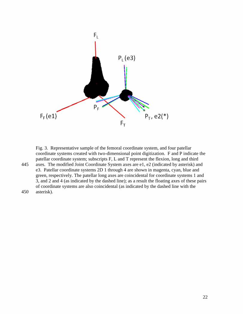
Fig. 3. Representative sample of the femoral coordinate system, and four patellar
coordinate systems created with two-dimensional point digitization. F and P indicate the
patellar coordinate system; subscripts F, L and T represent the flexion, long and third
axes. The modified Joint Coordinate System axes are e1, e2 (indicated by asterisk) and 445
e3. Patellar coordinate systems 2D 1 through 4 are shown in magenta, cyan, blue and
green, respectively. The patellar long axes are coincidental for coordinate systems 1 and
3, and 2 and 4 (as indicated by the dashed line); as a result the floating axes of these pairs
of coordinate systems are also coincidental (as indicated by the dashed line with the
asterisk). 450
23
List of Tables
Table 1. Landmarks used in the literature to create anatomical coordinate systems on the 455
patella and femur.
Femur Patella
Flexion
Axis
Line joining medial and lateral epicondyles
[2-6]
Line joining medial and lateral posterior
points of condyles [7-9]
Line joining centres of spheres fit to femoral
condyles [10,11]
Plane touching posterior condyles [12]
Parallel to tibial coordinate system at full
extension [13]
Line joining posterior point and lateral point
[9,18]
Line joining medial and lateral points [8,11]
Parallel to femoral axis at full extension [3]
Parallel to femoral axis at 90° [12]
Parallel to tibial coordinate system at full
extension [13]
Long
Axis
Anatomical (between two points along
femoral shaft) [1]
Anatomical (origin along centre of femoral
shaft) [4,6,7,10,11]
Mechanical (origin to centre of femoral
head) [2,3]
Trochlear (line along deepest portion of
trochlear groove) [12]
Parallel to tibial coordinate system at full
extension [13]
Line joining proximal and distal points
[7,8,18]
Posterior flat edge [19,20]
Perpendicular to flexion and third [11]
Parallel to femoral axis at full extension [3]
Parallel to femoral axis at 90° [12]
Parallel to tibial coordinate system at full
extension [13]
Between origin and distal point [2]
Line connecting insertions of quadriceps and
patellar tendons [10]
Third
Axis
Perpendicular to flexion/extension and long
axes [2,3,10]
Parallel to tibial coordinate system at full
extension [13]
Perpendicular to flexion and long axes [10]
Cross product of medial lateral axis and
vector from inferior apex along anterior
surface [11]
Parallel to femoral axis at full extension [3]
Parallel to femoral axis at 90° [12]
Parallel to tibial coordinate system at full
extension [11]
Perpendicular to plane containing medial,
lateral and distal points [2]
Origin
Deepest point of the trochlear groove where
it meets the intercondylar notch [8,14]
Most proximal point of the intercondylar
notch [15]
Most posterior point on the sulcus groove in
the axial plane [9]
Proximal point of intercondylar notch along
to anatomical axis [12]
Centre of the intercondylar notch [13]
Midpoint between medial and lateral
epicondyles [3,16]
Posterior point on axial midslice [8,9]
Midpoint of line joining medial and lateral
points of patella [2,11]
Centre of the patella [3,6,7,12,14,21]
Centre of the patella using most proximal,
distal, medial and lateral points [7]
Centre of the patellar ridge [13]
Projection of centre of patella onto line
connecting insertions of quadriceps and
patellar tendons [10]
Geometric centre [16]
24
Midpoint of centres of spheres fit to femoral
condyles [10,11]
Intersection between the screw axis of the
femur (helical axis) and the sagittal plane
bisecting the knee [17]
Centre of the posterior cruciate ligament
insertion [6]
Aligned with femur at full extension [3]
Table 2. Points that were digitized and calculated on the patella, listed with the intra-and 460
inter-investigator repeatabilities of landmark selection.
Description Abbreviation
Intra-investigator Inter-investigator
Mean ± 1SD Mean ± 1SD
(mm) (mm)
Most medial point selected on the axial
midslice Med-2 0.17 ± 0.12 0.63 ± 0.32
Most medial point selected in three
dimensions Med-3 0.50 ± 0.10 0.91 ± 0.08
Most lateral point selected on the axial
midslice Lat-2 0.20 ± 0.10 0.76 ± 0.43
Most lateral point selected in three
dimensions Lat-3 0.43 ± 0.02 0.65 ± 0.21
Most proximal point selected on the
sagittal midslice Prox-2 0.37 ± 0.07 0.44 ± 0.08
Most proximal point selected in three
dimensions Prox-3 0.37 ± 0.25 0.84 ± 0.27
Most distal point selected on the sagittal
midslice Dist-2 0.11 ± 0.02 0.27 ± 0.20
Most distal point selected in three
dimensions Dist-3 0.34 ± 0.04 0.60 ± 0.09
Most proximal point of patellar spine
selected on the sagittal midslice Prox.Spine-2 0.30 ± 0.21 0.29 ± 0.08
Most proximal point of patellar spine
selected in three dimensions Prox.Spine-3 0.55 ± 0.06 0.97 ± 0.39
Most distal point of patellar spine
selected on the sagittal midslice Dist.Spine-2 0.21 ± 0.19 0.28 ± 0.18
Most distal point of patellar spine
selected in three dimensions Dist.Spine-3 0.52 ± 0.42 0.79 ± 0.30
Most posterior point selected on the axial
midslice Post-2 0.33 ± 0.05 0.46 ± 0.11
Most posterior point selected in three
dimensions Post-3 0.70 ± 0.88 1.67 ± 0.85
Midpoint of Med-2 and Lat-2 Med.Lat-2 0.20 ± 0.06 0.49 ± 0.08
Midpoint of Med-3 and Lat-3 Med.Lat-3 0.34 ± 0.09 0.63 ± 0.24
Midpoint of Prox-2 and Dist-2 Prox.Dist-2 0.25 ± 0.11 0.29 ± 0.08
Midpoint of Prox-3 and Dist-3 Prox.Dist-3 0.35 ± 0.13 0.53 ± 0.18
Centre of Med-2, Lat-2, Prox-2, and Dist-
2 Centre-2 0.17 ± 0.07 0.32 ± 0.03
Centre of Med-3, Lat-3, Prox-3, and Dist-
3 Centre-3 0.24 ± 0.07 0.44 ± 0.15
25
Table 3. Landmarks used in the creation of the initial flexion and long axes for the four 465
patellar coordinate system definitions.
Name Flexion axis Long axis
2D-1 Med-2 and Lat-2 Prox-2 and Dist-2 [11,18]
2D-2 Med-2 and Lat-2 Prox.Spine-2 and Dist.Spine-2
2D-3 Post-2 and Lat-2 Prox-2 and Dist-2 [11,18]
2D-4 Post-2 and Lat-2 Prox.Spine-2 and Dist.Spine-2
3D-1 Med-3 and Lat-3 [8,11] Prox-3 and Dist-3 [7,8]
3D-2 Med-3 and Lat-3 [8,11] Prox.Spine-3 and Dist.Spine-3
3D-3 Post-3 and Lat-3 [9,18] Prox-3 and Dist-3 [7,8]
3D-4 Post-3 and Lat-3 [9,18] Prox.Spine-3 and Dist.Spine-3
Table 4. Mean (± 1 SD) absolute differences in the resultant kinematic angles between
the eight patellar coordinate systems (listed in Table 3) for all subjects across six knee 470
flexion angles. Comparisons are shown within the two-dimensional approaches, within
the three-dimensional approaches, and between the two- and three-dimensional
approaches that used the same landmarks for coordinate system creation. Significant
differences (p < 0.05) are indicated by a star (*).
475
Flexion (°)
2D-1 2D-2 2D-3 2D-4 3D-1 3D-2 3D-3
2D-2 10.8 ± 3.5*
2D-3 0.0 ± 0.0 10.8 ± 3.5*
2D-4 10.8 ± 3.5* 0.0 ± 0.0 10.8 ± 3.5*
3D-1 1.0 ± 1.2*
3D-2 1.4 ± 1.5 11.5 ± 3.0*
3D-3 1.0 ± 1.2* 0.0 ± 0.0 11.5 ± 3.0*
3D-4 1.4 ± 1.5 11.5 ± 3.0* 0.0 ± 0.0 11.5 ± 3.0*
Spin (°) 2D-1 2D-2 2D-3 2D-4 3D-1 3D-2 3D-3
2D-2 1.5 ± 1.5
2D-3 0.0 ± 0.0 1.5 ± 1.5
2D-4 1.5 ± 1.5 0.0 ± 0.0 1.5 ± 1.5
3D-1 3.4 ± 2.3
3D-2 3.5 ± 3.1 5.0 ± 3.8
3D-3 3.4 ± 2.3 0.0 ± 0.0 5.0 ± 3.8
3D-4 3.5 ± 3.1 5.0 ± 3.8 0.0 ± 0.0 5.0 ± 3.8
Tilt (°) 2D-1 2D-2 2D-3 2D-4 3D-1 3D-2 3D-3
2D-2 1.0 ± 0.8*
2D-3 21.1 ± 2.4* 22.1 ± 2.6*
2D-4 20.3 ± 2.5* 21.2 ± 2.4* 0.9 ± 0.7*
3D-1 2.5 ± 1.4*
3D-2 1.9 ± 1.1 1.8 ± 1.6*
3D-3 5.7 ± 4.8* 25.5 ± 5.8* 27.3 ± 6.2*
3D-4 3.3 ± 2.6* 22.2 ± 2.4* 24.0 ± 2.9* 4.7 ± 1.5*