Embed Size (px)
Citation preview
A Study of Pre-travel Variation of Coordinate Measuring
Machine with Different Stylus Configurations
AHMED SAEED ALI SAEEDAN
B051110303
UNIVERSITI TEKNIKAL MALAYSIA MELAKA
2015
UNIVERSITI TEKNIKAL MALAYSIA MELAKA
A Study of Pre-travel Variation of Coordinate Measuring Machine
with Different Stylus Configurations
This report submitted in accordance with requirement of the Universiti Teknikal
Malaysia Melaka (UTeM) for the Bachelor Degree of Manufacturing Engineering
(Manufacturing Process) (Hons.)
by
Ahmed Saeed Ali Saeedan
B051110303
03391942
FACULTY OF MANUFACTURING ENGINEERING
2015
UNIVERSITI TEKNIKAL MALAYSIA MELAKA
BORANG PENGESAHAN STATUS LAPORAN PROJEK SARJANA MUDA
TAJUK: A Study of Pre-travel Variation of Coordinate Measuring Machine with
Different Stylus Configurations
SESI PENGAJIAN: 2014/15 Semester 2
Saya AHMED SAEED ALI SAEEDAN
mengaku membenarkan Laporan PSM ini disimpan di Perpustakaan Universiti
Teknikal Malaysia Melaka (UTeM) dengan syarat-syarat kegunaan seperti berikut:
1. Laporan PSM adalah hak milik Universiti Teknikal Malaysia Melaka dan penulis. 2. Perpustakaan Universiti Teknikal Malaysia Melaka dibenarkan membuat salinan
untuk tujuan pengajian sahaja dengan izin penulis. 3. Perpustakaan dibenarkan membuat salinan laporan PSM ini sebagai bahan
pertukaran antara institusi pengajian tinggi.
4. **Sila tandakan ( )
SULIT
TERHAD
TIDAK TERHAD
(Mengandungi maklumat yang berdarjah keselamatan
atau kepentingan Malaysia sebagaimana yang termaktub
dalam AKTA RAHSIA RASMI 1972)
(Mengandungi maklumat TERHAD yang telah ditentukan
oleh organisasi/badan di mana penyelidikan dijalankan)
Alamat Tetap:
Tarikh: ________________________
Disahkan oleh:
Cop Rasmi:
DECLARATION
I hereby, declared this report entitled “A Study of Pre-travel Variation of
Coordinate Measuring Machine with Different Stylus Configurations” is the results
of my own research except as cited in references.
Signature :
Author’s Name : Ahmed Saeed Ali Saeedan
Date : 5th June 2015
APPROVAL
This report is submitted to the Faculty of Manufacturing Engineering of UTeM as
a partial fulfillment of the requirements for the degree of Bachelor of
Manufacturing Engineering (Manufacturing Process) (Hons.). The member of the
supervisory is as follow:
………………………………
P.M. Dr. Mohd Rizal bin Salleh
i
ABSTRACT
Coordinate measuring machine (CMM) is one of the sophisticated, most powerful and
versatile metrological instruments. CMM measurements are not accurate as they are
always subjected to errors due to various causes. Nevertheless, quantifying an error
and later uncertainty puts doubts on the validity of the measurement result. Such a
probe system is much responsible for the CMM measurement accuracy and the most
important parameter characterizing probe inaccuracy is the pre-travel variation. This
project studied the influence of using different stylus configurations toward the pre-
travel variations and later identify the source of errors and the factors affecting the
uncertainty of the measurement. Three factors were evaluated (stylus length, tip
diameter of the stylus, and the approach distance) and a full factorial design was
adopted for the experimental design followed by an ANOVA analysis to identify the
significance of the factors toward the pre-travel variation and the uncertainty of the
measurements. The experimental results showed significant effect of the three factors
on both the pre-travel variation and the uncertainty of the measurement and there was
an interaction between the stylus length and the tip diameter. It was also found that the
stylus length has much influence on the results than the tip diameter and the approach
distance was the least factor affected the measurements. Moreover, it was found that
the increment of stylus length lead to a significant variations of pre-travel and
uncertainties while the increment of the tip diameter at the smallest length of the stylus
reduced the error propagation. Also, it was found that the smallest approach distance
produced relatively higher pre-travel variation and uncertainties.
ii
ACKNOWLEDGEMENT
I would like to take this opportunity to express my heartily gratitude to my supervisor
Associate Professor Dr. Mohd Rizal bin Salleh. This project would not have been
possible without his guidance and support. I would like also to express my very great
appreciation to all the lecturers and technicians who had provided me the guidance and
help along the way to accomplish this project. I am grateful for the spirit support,
cooperation and guidance given by my friends. I would like as well to thank my fellow
course members in Bachelor Degree of Manufacturing Engineering (Manufacturing
Process) of UTeM, for their helpful comments and caring along my study.
iii
TABLE OF CONTENT
Abstract i
Acknowledgement ii
Table of Content iii
List of Tables vi
List of Figures vii
List Abbreviations ix
CHAPTER 1: INTRODUCTION 1
1.1 Overview / Background 1
1.2 Problem Statement 3
1.3 Objectives 4
1.4 Scope 4
1.5 Project Organization 5
CHAPTER 2: LITERATURE REVIEW 6
2.1 Types and Constructions of CMM 6
2.2 Probing System8
2.2.1 Classifications and Categories of Probing System 8
2.2.2 Touch-Trigger Probes 11
2.2.2.1 Kinematic Resistive Probe Operation 13
2.2.2.2 Strain-gauge and Piezo Probes Operation 14
2.2.2.3 Touch Trigger Probe Performance 16
2.3 Factors Influence the Probing Accuracy of CMM 19
2.3.1 Stylus Length 19
2.3.2 Stylus Tip Diameter 21
2.3.3 Probe Approach Distance 22
2.3.4 Approach Speed of the Probe 23
2.3.5 Sampling planning 24
2.4 Errors in Measurement 25
2.4.1 Sources of Errors 26
iv
2.4.2 Types of Errors 26
2.4.2.1 Systematic Error 27
2.4.2.2 Random Error 28
2.5 Uncertainties of Measurements 28
2.5.1 Sources of Uncertainty 29
2.5.2 Model of Measuring Uncertainty 30
2.5.2.1 Standard Uncertainty 30
2.5.2.1.1 Type A Evaluation 31
2.5.2.1.2 Type B Evaluation 31
2.5.2.2 Combined Standard Uncertainty 32
2.5.2.3 Expanded Uncertainty 33
CHAPTER 3: METHODOLOGY 34
3.1 Overview 34
3.2 Experiment Definition 36
3.3 Experiment Parameters and Variables 36
3.4 Design of Experiment (DOE) 37
3.5 Conducting the Experiment 39
3.6 Data Collection 40
3.7 Data Analysis 40
3.8 Findings and Conclusions 41
3.9 Summary 41
CHAPTER 4: RESULTS AND DISSCUSSION 42
4.1 Overview of the experiment and Data Collection 42
4.2 Results 43
4.2.1Analysis of Variance (ANOVA) 46
4.2.1.1 ANOVA Model for Uncertainty 46
4.2.1.2 ANOVA Model for Pre-travel Variation 49
4.2.2 Comparison of Probe Pre-travel Variation 52
4.2.2.1 Comparison of Stylus Length effect on the Pre-travel Variation 53
4.2.2.2Comparison of Tip Diameter Effect on the Pre-travel Variation 57
v
4.2.2.3 Comparison of Approach Distance Effect
on the Pre-travel Variation 62
4.3 Discussion 71
CHAPTER 5: CONCLUSION & RECOMMENDATION 75
5.1 Conclusion 75
5.2 Recommendation 77
REFERENCES 78
APPENDICES 83
A Gantt Chart
B Stylus Kit Technical data
C Data Collection
vi
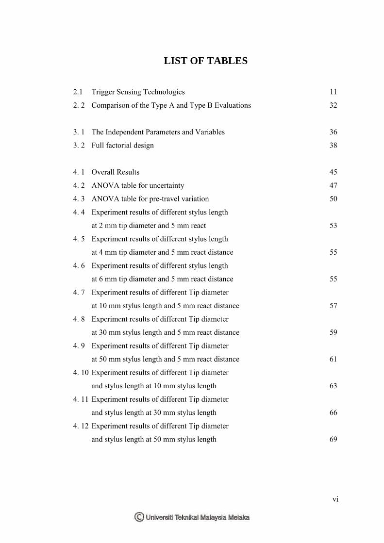
LIST OF TABLES
2.1 Trigger Sensing Technologies 11
2. 2 Comparison of the Type A and Type B Evaluations 32
3. 1 The Independent Parameters and Variables 36
3. 2 Full factorial design 38
4. 1 Overall Results 45
4. 2 ANOVA table for uncertainty 47
4. 3 ANOVA table for pre-travel variation 50
4. 4 Experiment results of different stylus length
at 2 mm tip diameter and 5 mm react 53
4. 5 Experiment results of different stylus length
at 4 mm tip diameter and 5 mm react distance 55
4. 6 Experiment results of different stylus length
at 6 mm tip diameter and 5 mm react distance 55
4. 7 Experiment results of different Tip diameter
at 10 mm stylus length and 5 mm react distance 57
4. 8 Experiment results of different Tip diameter
at 30 mm stylus length and 5 mm react distance 59
4. 9 Experiment results of different Tip diameter
at 50 mm stylus length and 5 mm react distance 61
4. 10 Experiment results of different Tip diameter
and stylus length at 10 mm stylus length 63
4. 11 Experiment results of different Tip diameter
and stylus length at 30 mm stylus length 66
4. 12 Experiment results of different Tip diameter
and stylus length at 50 mm stylus length 69
vii
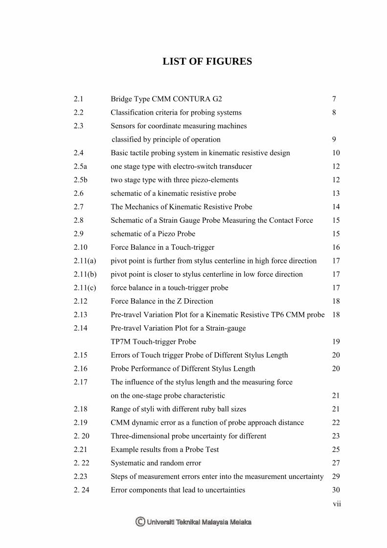
LIST OF FIGURES
2.1 Bridge Type CMM CONTURA G2 7
2.2 Classification criteria for probing systems 8
2.3 Sensors for coordinate measuring machines
classified by principle of operation 9
2.4 Basic tactile probing system in kinematic resistive design 10
2.5a one stage type with electro-switch transducer 12
2.5b two stage type with three piezo-elements 12
2.6 schematic of a kinematic resistive probe 13
2.7 The Mechanics of Kinematic Resistive Probe 14
2.8 Schematic of a Strain Gauge Probe Measuring the Contact Force 15
2.9 schematic of a Piezo Probe 15
2.10 Force Balance in a Touch-trigger 16
2.11(a) pivot point is further from stylus centerline in high force direction 17
2.11(b) pivot point is closer to stylus centerline in low force direction 17
2.11(c) force balance in a touch-trigger probe 17
2.12 Force Balance in the Z Direction 18
2.13 Pre-travel Variation Plot for a Kinematic Resistive TP6 CMM probe 18
2.14 Pre-travel Variation Plot for a Strain-gauge
TP7M Touch-trigger Probe 19
2.15 Errors of Touch trigger Probe of Different Stylus Length 20
2.16 Probe Performance of Different Stylus Length 20
2.17 The influence of the stylus length and the measuring force
on the one-stage probe characteristic 21
2.18 Range of styli with different ruby ball sizes 21
2.19 CMM dynamic error as a function of probe approach distance 22
2. 20 Three-dimensional probe uncertainty for different 23
2.21 Example results from a Probe Test 25
2. 22 Systematic and random error 27
2.23 Steps of measurement errors enter into the measurement uncertainty 29
2. 24 Error components that lead to uncertainties 30
viii
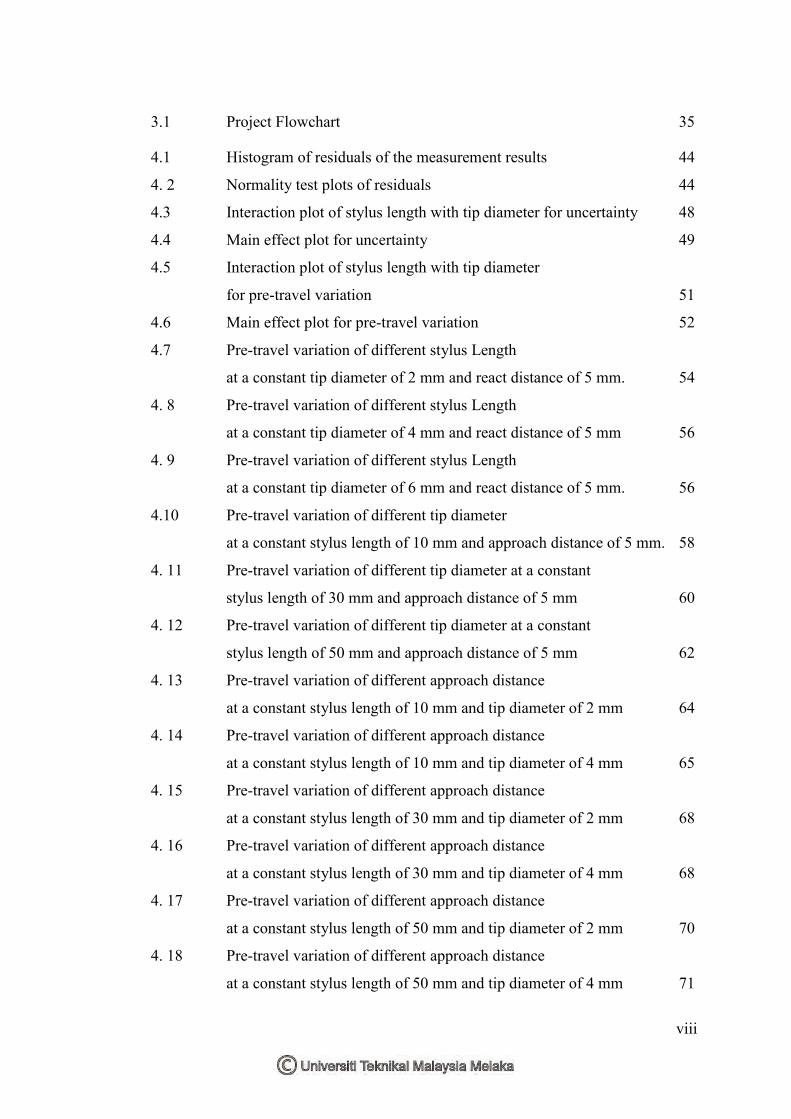
3.1 Project Flowchart 35
4.1 Histogram of residuals of the measurement results 44
4. 2 Normality test plots of residuals 44
4.3 Interaction plot of stylus length with tip diameter for uncertainty 48
4.4 Main effect plot for uncertainty 49
4.5 Interaction plot of stylus length with tip diameter
for pre-travel variation 51
4.6 Main effect plot for pre-travel variation 52
4.7 Pre-travel variation of different stylus Length
at a constant tip diameter of 2 mm and react distance of 5 mm. 54
4. 8 Pre-travel variation of different stylus Length
at a constant tip diameter of 4 mm and react distance of 5 mm 56
4. 9 Pre-travel variation of different stylus Length
at a constant tip diameter of 6 mm and react distance of 5 mm. 56
4.10 Pre-travel variation of different tip diameter
at a constant stylus length of 10 mm and approach distance of 5 mm. 58
4. 11 Pre-travel variation of different tip diameter at a constant
stylus length of 30 mm and approach distance of 5 mm 60
4. 12 Pre-travel variation of different tip diameter at a constant
stylus length of 50 mm and approach distance of 5 mm 62
4. 13 Pre-travel variation of different approach distance
at a constant stylus length of 10 mm and tip diameter of 2 mm 64
4. 14 Pre-travel variation of different approach distance
at a constant stylus length of 10 mm and tip diameter of 4 mm 65
4. 15 Pre-travel variation of different approach distance
at a constant stylus length of 30 mm and tip diameter of 2 mm 68
4. 16 Pre-travel variation of different approach distance
at a constant stylus length of 30 mm and tip diameter of 4 mm 68
4. 17 Pre-travel variation of different approach distance
at a constant stylus length of 50 mm and tip diameter of 2 mm 70
4. 18 Pre-travel variation of different approach distance
at a constant stylus length of 50 mm and tip diameter of 4 mm 71
ix
LIST OF ABBREVIATIONS
ANOVA – Analysis of Variance
CMM - Coordinate Measuring Machine
CMS – Coordinate Measuring System
CNC – Computer Numerical Control
DOE - Design of Experiment
GUM - Guide to the expression of Uncertainty Measurement
ISO - International Organization for Standardization
PTV – Pre-travel Variation
RSS - Root Sum of the Square
TP - Touch Probe
UTeM - Universiti Teknikal Malaysia Melaka
VIM - International Vocabulary of basic and general terms in Metrology
1
CHAPTER 1
INTRODUCTION
This chapter presents a general overview of coordinate measuring machines (CMMs),
states the problem of the project, and identifies the objectives as well as the scope of
the project. Generally, this project is carried out to study, evaluate and analyze the
probing system of CMM which is highly contributes to the uncertainty of CMM
measurement and reduce its accuracy.
1.1 Overview / Background
In relation to the continuous advances in science and technology, measurements role
has increased over the years in fields like manufacturing, information systems,
electronics, nuclear, space, etc. According to International Vocabulary of Basic and
General Terms of Metrology (VIM), it defines measurement as a process of
experimentally obtaining one or more quantity values that can reasonably be attributed
to a quantity (VIM, 2012).
Measurements have become a tool of science. Metrology, however, is the science of
measurement. It comprises all theoretical and practical aspects of measurement, such
as units of measurement and their standards, measuring instruments and their field of
application.
The list of metrology instruments and their capabilities have grown through the years.
Coordinate measuring machines (CMMs) are one of the sophisticated, most powerful
2
and versatile instruments CMM is an advanced quality control system. It used for
many purposes to make inspection meet modern production requirements. Its primary
function is to measure the actual shape of a workpiece, and compare it against the
desired shape and evaluate the metrological information such as size, form, location,
and orientation.
CMM is traced back to the year 1959 where it first appeared commercially at the
International Machine Tool exhibition in Paris, exhibited by the British company
Ferranti. The key element of the development of the CMM was the availability of an
accurate, long-range, electronically compatible digital measuring system (Hocken &
Pereira, 2012).
CMM is used in assembly and manufacturing processes to test a part or assembly
against the design intent. It precisely records the X, Y, and Z coordinates of the target.
Then, it generates points and analyses them, through algorithms, for the construction
of features. These points are collected by using a probe that is positioned manually by
an operator or automatically via computer control. The part for measurement is placed
on the table of the CMM and aligned along the coordinate axis of the machine. The
coordinate system of the part is created by the software and transferred to the
coordinate system of the machine.
The economic success of most manufacturing industries is critically dependent on how
well its products are made, a requirement in which measurement plays a key role.
Coordinate Measuring Machine (CMM) is one of the most adequate measuring
machines to meet the requirement. Due to high sensitivity and speed, CMMs have to
be in a controlled environment to yield accurate results. Even with the advent of the
CMM digital equipment readout and software packages to compensate errors and
improve measurements, these measurements are not accurate because they are always
subject to errors that are caused by either humans or materials. Quantifying an error to
later quantify an uncertainty proves that the validity of the measurement result is
doubted.
3
1.2 Problem Statement
There are many factors affect the uncertainty of CMM measurement. These effects
that interact might be due operator when selecting a different probe or stylus. Other
issues that can highly reduce the accuracy measurement of CMM are those errors
related to temperature variations, vibrations, and even dirt. Different errors related to
CMMs performance could be geometric errors due to the limited accuracy of the
individual machine components such as guideways and measuring systems, errors
related to the final stiffness of the moving parts, and thermal errors related to heat and
cooling source in the environment, like lighting, air conditioning, ventilation,
humidity, people around the machine and heat generated by the machine itself.
Quantifying uncertainty of CMM measurements is a very complex object, however
minimizing an error factor will contribute to the accuracy improvement of CMM
measurements (Ali, 2010). Such a probe system of CMM is much responsible for the
coordinate measurement accuracy. It includes stylus and stylus tip which have its own
dynamic characteristics during the measuring process. The probe stylus tip is a key
element of coordinate measurements; it contributes to the overall performance of the
CMM.
The most important parameter characterizing probe inaccuracy is the pre-travel
variation which can be determined using a master sphere of known radius (Woźniak
& Dobosz, 2005). Desai and Bidanda (2006) mentioned that the type of probe used for
measurement is an important factor that influences the accuracy of CMM; such a
touch-trigger probe, it has several factors related to its motion (e.g. approach speed,
and probe acceleration) and configuration (e.g. probe stylus length) which influence
its performance. Therefore, this study was carried out to compare the influence of
using different stylus configurations toward the pre-travel variations and later identify
the source of errors and the factors affecting the uncertainty of the measurement in
order to minimize errors and increase the overall performance and measurement
accuracy of the CMM.
4
1.3 Objectives
The objectives of this project are:
i. To identify the probing factors affecting the uncertainty of measurement.
ii. To compare the pre-travel variation of touch-trigger probe using different
range of stylus configuration and extensions.
1.4 Scope
The accuracy of CMM measurement can be affected by various errors sources. In order
to improve and obtain more accurate results, the source of errors should be eliminated
or controlled. However, this study is focused on the performance and the evaluation
of uncertainties of touch-trigger probe utilizing different stylus configurations and
extensions which is highly related to reduce the accuracy of CMM measurements. The
scope of this project will ensure that the project is conducted within its intended
objectives and it should be eventually achieved. The scopes of this project are listed in
the following points:
i. Literature study on the related theories and most updated researches will be
reviewed.
ii. The parameters to be used which are highly related to reduce the CMM
accuracy are probe stylus length, different tip diameter and probe approach
distance.
iii. The measurements will be done using a master sphere of a known radius.
iv. All results will be compared, and errors, uncertainties and pre-travel variation
of the result will be evaluated as well.
5
1.5 Project Organization
This project is divided into two phases. The first phase comprises of three chapters.
The first chapter contains a general overview of coordinate measuring machines
(CMMs), states the problem of the project, and identifies the objectives as well as the
scope of the project. In the second chapter, a literature review will be provided to
investigate, analyze and compare the various and most updated research on the area
related to the project. While the third chapter provides a methodology to accomplish
the project, where it explains and illustrates the direction and the flowchart(s) of the
project. The second phase will then start after all studies being carried out which
includes chapter 4 and chapter 5. The results and discussion will be provided in chapter
4, while the last chapter will enclose the project with conclusions and suggestions. The
Gantt charts of phase one and phase two are provided in appendix A.

6
CHAPTER 2
LITERATURE REVIEW
Many researches were conducted on evaluating the performance of CMM in general.
Some of such researches are on probing system where as others were on identifying
the dynamic errors of CMMs and other likely studies. The main purpose of this chapter
is to investigate, analyze and compare the various and most updated research on the
area of CMM probing systems. This chapter basically presents the literature reviews
on the areas of the research. A brief review about the types of CMM will be presented.
A classification of probing system and its types will also be reviewed as well as the
mechanism and the performance of touch trigger probe. In addition, a brief overview
about uncertainties and errors in CMM measurements and their sources will be
covered. Finally, the most factors influence the accuracy of CMM probing system will
be discussed.
2.1 Types and Constructions of CMM
The general basic components of any CMM consists of three linear axes( x , y, and z)
mechanical frame, a probing system, a control unit, and a computer system which are
integrated to enable readout and analyze the distances of the part being measured
(Hocken & Pereira, 2012). The mechanical frame provides a guide way that enable
precise movement along a straight line. Each of these guide ways (x, y, z) has a carrier
that moves along by which it enables the second carrier to move along a straight line
based on the first guide way. Each of three linear axes is fitted with a precision scale
that records the position of the carrier measured from a reference point. The probe
system is fitted to the carrier on the third axis, and the object is being measured by the
7
probe touches. Subsequently, the measurement system records the position of all three
axes (Ratnam, 2009).
There are several physical configurations of CMMs. Each of these configurations
plays an important role in its performance aspects such as accuracy, flexibility, cycle
time, and life time cost. Although there are many commonly used configurations of
CMMs but they can be grouped into five basic types as follows:
1. Cantilever type,
2. Bridge type,
3. Horizontal arm type,
4. Column type and
5. Gantry type.
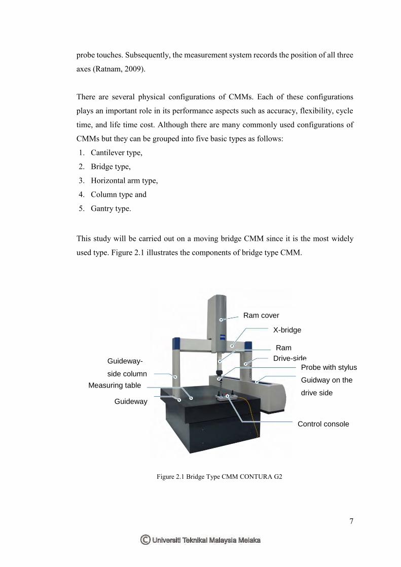
This study will be carried out on a moving bridge CMM since it is the most widely
used type. Figure 2.1 illustrates the components of bridge type CMM.
Guideway-
side column
Measuring table
Ram cover
X-bridge
Ram
Drive-side
Probe with stylus
system Guidway on the
drive side
Control console
Guideway
Figure 2.1 Bridge Type CMM CONTURA G2

8
2.2 Probing System
The probe is one of the most important elements of coordinate measuring machine
(CMM), it integrates the entire measuring system and forms a link between the
machine and the work to be measured and it is responsible for the overall accuracy of
a measurement (Weckenmann et al. 2004). It is the sensing element that makes contact
and causes readings to be taken.
2.2.1 Classifications and Categories of Probing System
There are a verity of probes exist, these can be categorized into two different types of
probe: contact (tactile) and non-contact probes which are practically used in modern
CMMs (Hocken & Pereira, 2012). The type of probe to be utilized however is an
important aspect to take into account when the precision of a particular CMM is going
to be evaluated (Puertas et al., 2013).
Ali (2010) noted in his research that contact probes can also be classified into two
specific families of manual hard probes and touch-trigger probes. However, Woźniak
and Dobosz (2003) stated that contacting probes are categorized into tough trigger and
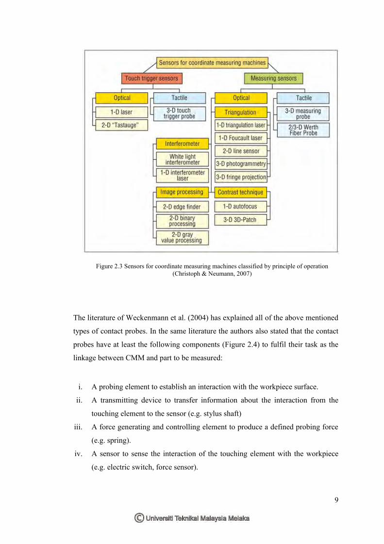
measuring systems. Figure 2.2 calcifies the huge variety of probing systems to distinct
application-oriented aspects, and Figure 2.3 classifies the probing systems according
to principle of operation.
Figure 2.2 Classification criteria for probing systems (Hocken & Pereira, 2012).
Probing systems for
coordinate metrology Kinematics
Mode of
operation Displacement measurement
Size
Contact
detection
Moving during
probing
Operational principle
Probing force generation
9
The literature of Weckenmann et al. (2004) has explained all of the above mentioned
types of contact probes. In the same literature the authors also stated that the contact
probes have at least the following components (Figure 2.4) to fulfil their task as the
linkage between CMM and part to be measured:
i. A probing element to establish an interaction with the workpiece surface.
ii. A transmitting device to transfer information about the interaction from the
touching element to the sensor (e.g. stylus shaft)
iii. A force generating and controlling element to produce a defined probing force
(e.g. spring).
iv. A sensor to sense the interaction of the touching element with the workpiece
(e.g. electric switch, force sensor).
Figure 2.3 Sensors for coordinate measuring machines classified by principle of operation (Christoph & Neumann, 2007)
10
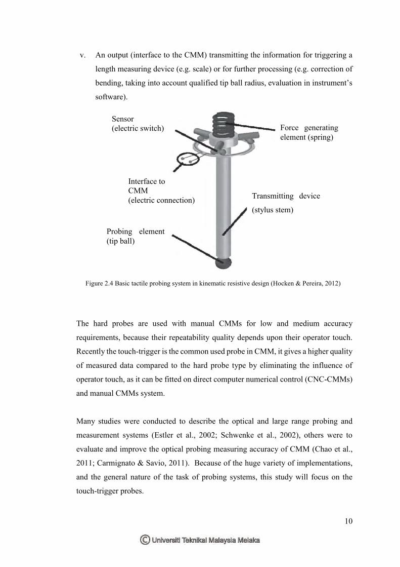
v. An output (interface to the CMM) transmitting the information for triggering a
length measuring device (e.g. scale) or for further processing (e.g. correction of
bending, taking into account qualified tip ball radius, evaluation in instrument’s
software).
The hard probes are used with manual CMMs for low and medium accuracy
requirements, because their repeatability quality depends upon their operator touch.
Recently the touch-trigger is the common used probe in CMM, it gives a higher quality
of measured data compared to the hard probe type by eliminating the influence of
operator touch, as it can be fitted on direct computer numerical control (CNC-CMMs)
and manual CMMs system.
Many studies were conducted to describe the optical and large range probing and
measurement systems (Estler et al., 2002; Schwenke et al., 2002), others were to
evaluate and improve the optical probing measuring accuracy of CMM (Chao et al.,
2011; Carmignato & Savio, 2011). Because of the huge variety of implementations,
and the general nature of the task of probing systems, this study will focus on the
touch-trigger probes.
Force generating element (spring)
Transmitting device
(stylus stem)
Probing element (tip ball)
Sensor (electric switch)
Interface to CMM (electric connection)
Figure 2.4 Basic tactile probing system in kinematic resistive design (Hocken & Pereira, 2012)


![Volumetric Transformation Of Brain Anatomy - Medical ... · to a standard atlas coordinate space [11]. Registration to an atlas removes individual anatomical variation and allows](https://img.pdfslide.us/doc/110x75/5f2d1074a19e85370f5ab2af/volumetric-transformation-of-brain-anatomy-medical-to-a-standard-atlas-coordinate.jpg)