Embed Size (px)
Citation preview

200 I'HILIPS TECHNICAL REVIEW Vol. 1, No. 7
THE DISK TEST AS A R.~PID METHOD FOR ESTIMATING THEMACHINABILITY OF STEEL
(Continued from p: 187) ,
In the first part ofthis paper the general procedureadopted in the Taylor test and the disk test wasdiscussed and the relation between' these twomethods of test analysed. In the present sectionthe experiments carried- out here and the resultsarrived at are reviewed .
.General Experimental Details
'Materials Used. To facilitate a discussion ofthe test made, full details of all types of steel uscdin these investigations are given in Table I.
Cooling agents. In accordance with the experi-mental work carried out by other investigators nocooling agents or lubricants were used in the presentwork. Although the absence of" a cooling agentconsiderably reduces the cutting efficiency of cuttingtools, the advantage gained is that the éxperimentsare-more closely reproducible.Shapes 'of Cutting Tools Used. In his
experiments Brandsma employed tools withstraight sides, and in later work adopted knife-edge cutters' of the type already illustrated in figs. 1and 3. The shape of these tools .is shown moreclearly in figs. '6 and 7. In fig.6 the sizes of allangles are given. It is seen from the last but onecolumn in Table I that the cutting angle was nottaken the same for all steels; in fact the mostsuit'able angle for each particular steel was selected.The only difference between the cutting tools usedin the disk tests (see figs. 3 and 7) and t~ose used
in the 'I'a ylo r tests (see fig. I) was" that in theformer the back of the tool was ground down so
. that the cutting edge alone was in ,~~ntact with thetest disk .. The cutting properties of the steels areprobably very little influenced by this modification.
---
2'
/6586
Fig. 6. Cutting tool (cutter angle 90 deg.) with horizontal :edge. a = Cutting angle. fJ = Principal angle of clearance.e = Secondary cutter angle. rp = Secondary angle of clear-ance. h = Blunting width. cl ~ Depth of cut. " =Widthof cut. The various cutting angles used for the differenttypes of steel are given in Table 1. With all steels, a, f3 and rpwere each equal to 30° and h was 0·5 mm.
Table 1. Survey of all the steels investigated -,.Approx. percentage composition of components other .
,. than Fe - .., .-..;:l ..... 0.. C,) _"'e<>
S '" "'--~- ';g S '"..... 1'1"'0
, Type .... S '" ;:l 1'1 State in which used 0 l'I.gg1'1 1'1 ....;:l ;:l ;:l '" .., 0> 1'1 '" '"0 1'1 'd .., 01""1 J..iCt')0 0 ..d ..d ;.e 13 ..>:
..,'" b'nil C,) 0:1 "0
.... 0:1 __
:s P< P< 0:1 eo ..Cl C,)..Q
eo .;j P=l..d00:1 '" "3 1'1 0 1'1 0 Z I': ::::!-U (J) 0 0:1 II 0:1 U ~ ~..d (J),
p., i>- e;,.) ::s ~.. "
Carbon Steei 1 0.0.8 <Ó.5 0.08 0.15 - - <0..8 - - - - Forged 25° 116Carbon Steel II 0.15 <0.35 <0.04 <0.04 - - <0.40 - - - - "Normalised" 25° 121Carbon Steel III OAS <0.35 <0.03 <0.03 - - <0.8 - - - - "Normalised" 20° 174-Chromium steel 0.12 <0.35 <0.03 <0.03 - 0.4 <0.40 - - - - Soft annealed 25° 107Nickel-chromium steel 1 0.14, <0.35 <0.03 <0.03 - 0.75 <0.5 . - 3.5 - - Soft annealed 20" 175Nickel-chromium steel II 0..30 <0.35 <0.03 <0.03 - 1.0 0.6 - 3.5 OA - Heat-refined 15° 311Nickel-chromium steel III 0..35 <0.35 <0.03 <0.03 - 1.2 <0.6 - 4.5 - - Soft-annealed 15° 263Tool steel 1 1.1 0.3 <0.03 <0.03 - 1.0 1.0 - - - 1.0 Soft-annealed 15° 216Tool steel II 2.2 0.6 <0.0.3 <0.03 - P 0.25 - - - - Soft-annealed . 15° 241
---- -- - -- __ - - -- -
H~d.n,d=d<wi,,=.ol.d I .Cobalt high-speed steel 0.7 <0.35 1.5 5 <0.25 16 20Vanadium high-speedsteel 1.2 3.5 5 - - 0.7 15 Hardened as delivered '
\ '
)
JULY 1936 SHORT TIME TESTING FOR THE MACHINABILITY 201
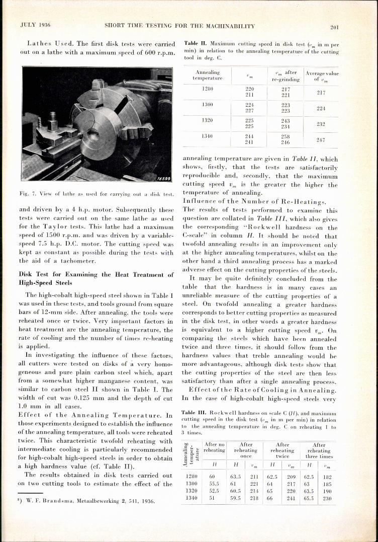
Lath esUs ed. The first disk tests were carriedout on a lathe with a maximum speed of 600 r.p.m.
Fig. 7. View of In the as used for parrying out a disk test.
and driven hy a 4 h.p. motor. Subsequently thesetests were carried out on the same lathe as usedfor the Taylor tests. This lathe had a maximumspeed of 1500 r.p.m. and was driven by a variable-speed 7.5 h.p , D.C. motor. The cutting speed waskept as constant as possible during the tests withthe aid of a tachometer.
Disk Test for Examining the Heat Treatment ofHigh-Speed Steels
The high-cohalt high-speed steel shown in Table Iwas used in these tests, and tools ground from squarebars of 12-mm side. After annealing, the tools werereheated once or twice. Very important factors inheat treatment are the annealing temperature, therate of cooling and the number of times re-heatingis applied.
In investigating the influence of these factors,all cutters were tested on disks of á very homo-geneous and pure plain carbon steel which, apartfrom a somewhat higher manganese content, wassimilar to carbon steel 11 shown in Tahle 1. Thewidth of cut was 0.125 mm and the depth of cut1.0 mm in all cases.Effect of the Annealing Temperature. Inthose experiments designed to establish the influenceofthe annealing temperature, all tools were reheatedtwice. This characteristic twofold reheating withintermediate cooling is particularly recommendedfor high-cohalt high-speed steels in order to obtaina high hardness value (cf. Tahle II).The results obtained in disk tests carried out
on two cutting tools to estimate the effect of the
8) W. F. Brandsma, Metaalbewerking 2, 541, 1936.
Table U. Maximurn cutting speed in disk test (Pm in m permin) in relation to the annealing temperature of the cuttingtooI in deg. C.
Annealingtemperature " after IAverage valueIlm
Tn
rc-grinding of IJm-----220 217 217211 221
----224, 223 224227 223225 243 232225 23~,244 258 247241 246
1280
1300
1320
1340
annealing temperature are given in Table 11, whichshows, firstly, that the tests are satisfactorilyreproducible and, secondly, that the maximumcutting speed Vno is the greater the higher thetemperature of annealing.Influence of the Number of Re-Heatings.The results of tests performed to examine thisquestion are collated in Table 111, which also givesthe corresponding "R 0 ckwe11 hardness on theC-scale" in column H. It should be noted thattwofold annealing results in an improvement onlyat the higher annealing temperatures, whilst on theother hand a third annealing process has a markedadverse effect on the cutting properties of the steels.It may be quite definitely concluded from the
table that the hardness is in many cases anunreliable measure of the cutting properties of asteel. On twofold annealing a greater hardnesscorresponds to hetter cutting properties as measuredin the disk test, in other words a greater hardnessis equivalent to a higher cutting speed Vm' Oncomparing the steels which have been annealedtwice and three times, it should follow from thehardness values that treble annealing would hemore advantageous, although disk tests show thatthe cutting properties of the steel are then lesssatisfactory than after a single annealing process.
Effect ofthe Rate of Cooling in Annealing.In the case of high-cobalt high-speed steels very
Table UI. RockweIl hardness on scale C (/-/), and maximumcutting speed in the disk test (om in m per min) in relationto the annealing temperature in deg. C on reheating 1 to3 times.- -
Àfter no I AfterI
After
IAfterbil
.: 0
.:..=1~Q.) reheating reheating reheating reheatingOl P< ....I~ a .El once twice three times
.: " OlJ-/ I H I I 1-1 I I I-I I<'"' firn. Urn 1',11.
1280 60 63.5 211 62.5 209 62.5 1821300 55.5 61 221 64 217 63 1851320 52.5 60.5 214 65 220 63.5 1901340 51 59.5 218 66 24,1 65.5 230
202 PIHLIPS TECHNICAL REVIEW Vol. 1, No. 7
\ \\' 1\ "'. I'" 1\\\ \ I"\.""~ickel-chromi~m ste~/)u\
1"- \. \ I"\ '\ -, 'Icarbon steell \; chromium steel
\ ~\1\ 1\ Î"\ "- I. \ r\. foolsleel I carbon sfee'.!!
\ '\. '\.
\ 1\ .", \.. \ .\ \\ -, \ -, '\ -,.\ \ \ \ carbon sleël m ,. \. \ f\. 4
Î'\ickel-ChrOmium - .~.. loolsleel D - ~ nicket-chromium sleel ii_~ i\ sfeell \ \
-\ .\\ \ \ -, \ \ '\1 1\ I\. \ I
rapid cooling is not desirable in view of the riskof hardness cracks appearing and of the prematurecrumbling of. the cutting edge on the lathe. The.effect of cooling was studied by cooling in compressed. air, ~lower, cooling in the fairly quiescent hot airof a furnace and still slower cooling in a very highly-insulating kieselguhr. As it was intended to detectparticularly any brittleness. developing, a groove13 mm wide was cut radially in the disk in such amanner, that the cutting was interrupted once during'each revolution. The results 'of these experimentsare give'n in Table IV, where it is shown that the
Table IV. RockweIl hardness <inscale C (H), and maximumcutting 'speed in the disk test (vm in m per min) in relationto the annealing temperature in deg. C. and the rate of cooling
. during annealing. .
Vmafter Aver-re- age. d value
g~m -. ofvmg . m
--+---'--+I---~::--'-- --.----.1300·1 Compressed air 1
1
Fairly slow 63.5 *) 214. 214.Furnace Slow 64 199 200 200I Kieselguhr Very slow 60.5 185 185 185
1320 I ~ompres~ed air I Fairly slow! 64.5 -2-23---2-3-7---23-0-Furnace ISlow 163.5 220 207 213Kieselguhr V~ry slow ,62 196 ~ 197
1 ' 1. 1340 I Furnace i Slow . 164 226 220 223
Kieselguhr IVery slow 163.5 2! 7 157 187_
Rate ofcooling 1-1Cooling in
*) Gradually became useless.
cutting ability increases with the rate 'of coolingand thàt it is barely affected by periodic interrup-tion. Whether the brittleness can be evaluated in. this way, therefore appears very doubtful, althoughsome information- on this point was furnished bya number of works tests and a metallographicexamination of the structure. On the basis of theseexperimènts and the results 'of the disk tests de-
60
4030
-,
.20TT:
43
2
20 30 40 50
scribed above, 'the optimum heat treatment requiredfor -the steels was established.
Disk Test for Testing and Classifying Steels noeordlngto their Machinability 9)
To determine whether the results obtained indisk tests are in eonoordance with those found bythe Taylor test, a large number of cxpcrimentswere carried out with the first nine steels enumeratedin Table I. In thes~ tests those cutting tools wereused which had been found best suited for both'the Tay 10r and disk tests, i.e. the exact instantat which the edge crumbled could be readilyobserved in each case, this not being always thecase with other forms of cutting tools. All steelsused in the investigation described below weremade from high-speed vanadium steel (deliveredhardened] given in Table 1.
In both the Tay 10r and the disk tests the depthof cut d 'and the width of cut a were 1.00 and 0.26mm respectively. With each of the steels studied,the -material for both the Tay l or and the disktests was taken from the same bar; only with toolsteel II was this not possible as the available bardiameter for carrying out the disk test was toosmall. But disks of sufficiently large diameter wereavailable. The diameter 'Do of the hole in the discwas again 50 mm in all tests.
In all Tay l or tests, always the same three cutting. tools were used in a continuous series ofmeasurementsfor plotting the complete v- T curve with all types.of steel P}, so that the final results given below
0) J. R. J. van Dongen and J. G. C. Stegwee, Metaal-bewerking 3, 1 and 4.9, 1936. Special attention is calledto the second part of this paper, which gives a compre-hensive summary of all quantitative measurements.
'10) In othe~ words, after plotting one point of the u-T curvethe worn cutting tool was reground before plotting thenext point, and after the whole v-T curve had been plottedthe same process was' repeated with each of the other twotools.
60
o30
20
1086
3
2
60 70 80 90 100 200150-- __ v fm/min)
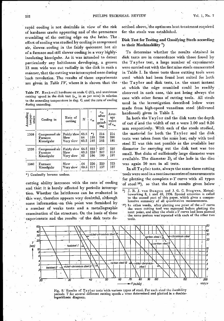
Fig. 8;' Results of Ta ylor tests with various types of steel. For each steel the durabilityperiods T for several different cutting speeds v were determined and plotted in a double-logarithmic diagram.
I 158.37
JULY 1936 SHORT TIME TESTING FOR THE MACHINABILITY 203
may be regarded as the averages of three completesets of tests. Three different tools were similarlyused in the disk tests and with each tool the N-vmcurves for all the steels were' plotted. Here againthe final result given is a n:ean of three completeseries of tests.The results obtained in the Tay lor tests are
shown graphically in fig. 8 and those in the disktests in fig.9. The principal values derived fromthe two graphs being a comparison between thetwo tests are collated.in Table V.'In addition, the cutting speed Vao corresponding
Table V. Results of Taylor and. disk tests (llm in m permin) in relation to the cutting speed.
Matcri ITaylor tests
'
Disktestsa erra
N Ic*)I"l*) v30 I "60 "m(100)
Chromium steel 8 178 178 115 105 282Carbon steel 1 10 152 152 107 1~~ 24·3Carbon steelIl 7 135 135 iJ7 225Nickel-chromium steel 1 6 122 122 68 61 167Carbon steel III 11 79 79 57 54 112Nickel-chromium steel III 8 57 57 37 34 83Nickel-chromium steelll 11 4·8 48 35 33 64Tool steel 1 12 45 45 34 32 62Tool steelIl 11.5 29 29 22 20.5
133.5
") The values of C and v1 are in agreement, although thedimensions of these magnitudes are different.
Vmax(m/min)
tI~
400 /000 /ZJO
/sas«---- ... N {omw/min}
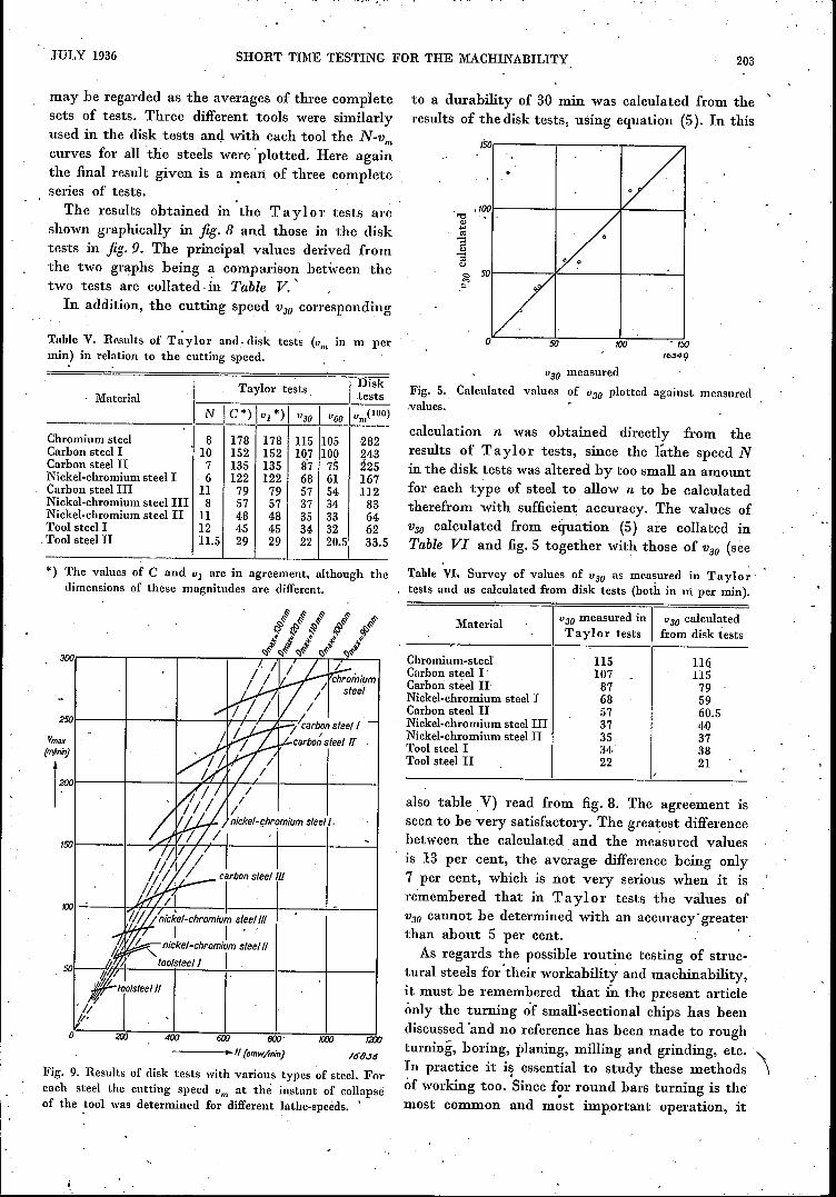
Fig. 9. Results of disk tests with various types of steel. Foreach steel the cutting speed "m at the instant of collapseof the tool was determined for different lathe-speeds. '
to a durability of 30 min was calculated from theresults of the disk tests, using equation (5). In this
/6349
"30 measuredFig. 5. Calculated values of "30 plotted against measured.values,
calculation n was obtained directly from theresults of Taylor tests, since the lathe speed Nin the disk tests was altered by too small an amountfor each type of steel to allow n to be calculatedtherefrom with sufficient accuracy. The values ofV30 calculated from equation' (5) are collated inTable VI and fig. 5 together with those of V30 (see
Table VI. Survey of values of V30 as measured in T'ny lor :tests and as calculated from disk tests (both in rri per min).
V30 measured in I V30 calculatedTay lor tests from disk tests
Material
116115795960.540373821
Chromium-steelCarbon steel I'Carbon steel UNickel-chromium steel 1Carbon steel 11Nickel-chromium steel IIINickel-chromium steelIlTool steel 1Tool steelIl
11510787685737353422
also table. V) read from fig. 8. The agreement isseen to be very satisfactory. The grea~est differencebetween the calculated and the measured valuesis 13 per cent, the average difference being only7 per cent, which is not very serious when it isremembered that in Taylol' tests the values ofV.JO cannot be determined with an accuracy' greaterthan about 5 per cent.As regards the. possible routine testing of struc-
tural steels for' their workability and machinability,it must be remembered that in the present articleonly the turning of small-sectional chips has beendiscussed 'and no reference has been made to roughturning, boring, planing, milling and grinding, etc. '\In practice it i~ essential to study these methods \of working too. Since f~r round bars turning is the'most common and most important operation, it
~, ,
204, PHILIPS TECHNICAL REVIEW Vol. 1, No. 7
should be possible to obtain satisfactory data ofthe machinability of various materials with thedisk test by employing widely-different sectionsof chips.
curacy and, over a wider range. That an investi-gation over these lines is worth while is evident froma consideration of the advantages which the disktest offers over the Tay lor test. It is sufficient to
oCHROMIUM STEEL
/00 200 m o 100 2fio
_- .. BRINELL HARDNESS10/3000/30
CARBON STEEL [
CARBON STEEL n
NICKEL -CHROMIUM STEEL [1- _
CARBON STEELm 1----NICKEL -CHROMIUM STEEL In1------I/!CKfI. -CHROMIUM STEEL u 1- _
TOOL STE£Ll!- _
TOOLSTEEL n -----
_· ..V30MEASUREÓ[TAYLORTEST}J •
=-"V30 CALCULATEO(OISK TEST) (m/mlfl)3l1J 0 50 100
I
~ ló818
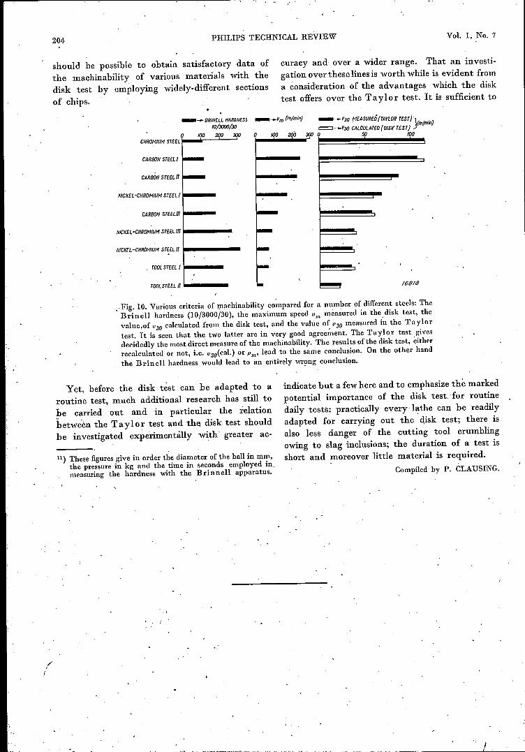
,Fig. 10. Various criteria of machinability compared for a number of different steels: TheBrinell hardness (10/3000/30), the maximum speed "". measured in the.disk test, thevalue.of "30 calculated from the disk test, and the value of "30 measured in the Taylortest. It is seen that the two latter are in very good agree~ent. The Taylor test givesdecidedly the most direct measure of the machinability. The results of the disk test, eitherrecalculated or not, i.e. 1J30(cal.)or Pm' lead to the same conclusion. On the other handthe Brinell hardness would lead to an entirely wr!lng conclusion.
Yet, before the disk test can be adapted to aroutine test, much additional research has still tope carried out and in particular the relationbetwe'én the Tay lor test and the disk test shouldbe investigated experimentàlly with' greater ac-
11) These figuresgive in order the diameter of the ball in mm,the pressure in kg and the time in seconds employed in.measuring the hardness with the Brinnell apparatus.
indicate but a fewhere and to emphasize the markedpotential importance of the disk test. for routinedaily tests: practically every lathe can be readilyadapted for carrying out the disk test; there isalso less danger of the cutting tool crumblingowing to slag inclusions; the duration of a test isshort and moreover little material is required.
Compiled by P. CLAUSING.
rI