Embed Size (px)
Citation preview
1
The development of a Superconducting Undulator for the
ILC Positron Source
James RochfordOn behalf of the HeLiCal collaboration
2
Scope
Prototype design and manufacture
• 4m Module design
• Magnet Testing and integration
• Assembly of 4m module
• Testing of the final prototype
Summary of helical development programme
• Design drivers
• Magnetic modelling
• Prototype research and development
• Manufactured specification
Introduction• Helical Collaboration
• ILC requirements
3
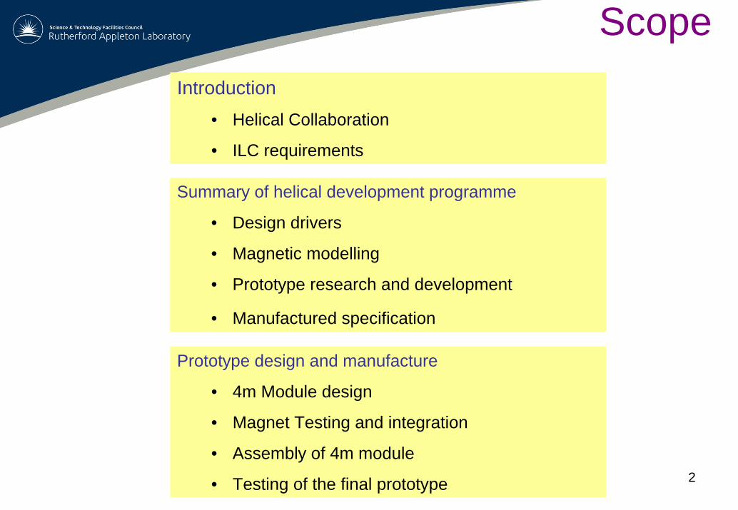
Helical
Collaboration membersASTEC:J.A. Clarke, O.B. Malyshev, D.J. Scott, B. Todd, N RyderRAL:E. Baynham, T. Bradshaw, J. Rochford, A Brummit, G Burton, C Dabinett,S. Carr, A LinternUniversity of Liverpool :I.R. Bailey, J.B. Dainton, P. Cooke, T. Greenshaw, L. MalyshevaDESY :D.P. Barber University of Durham :G.A. Moortgat-Pick Argonne:Y. Ivansuhenkov
ASTECPermanent magnet undulatorImpedance calculationsWakefield heatingVacuum considerationsSpecification (plus Liverpool and Durham)
RAL Technology deptSuperconducting undulatorMagnetic modellingPrototypingMechanical designManufacture
Helical collaboration
• Argue physics case for polarised positrons
• Prototype undulator
• permanent magnet
• superconducting
4
ILC
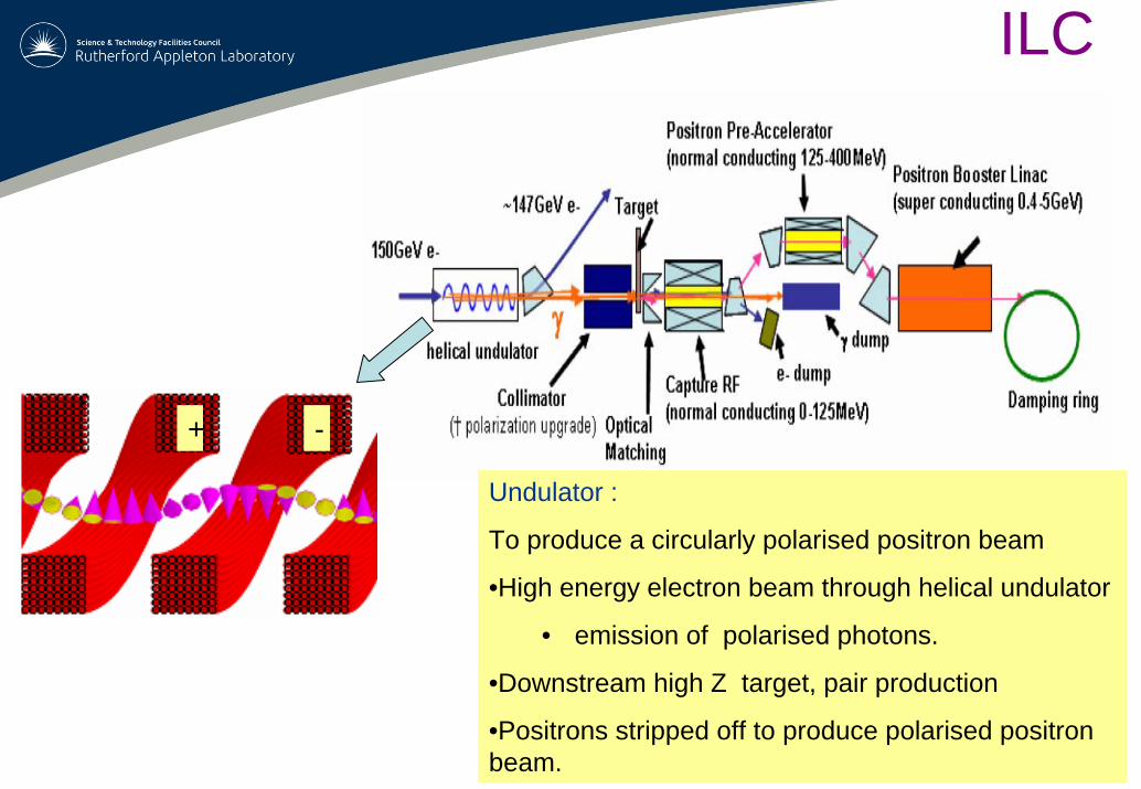
Undulator :
To produce a circularly polarised positron beam
•High energy electron beam through helical undulator
• emission of polarised photons.
•Downstream high Z target, pair production
•Positrons stripped off to produce polarised positron beam.
+ -
5
0.4
0.6
0.8
1.0
1.2
9.0 10.0 11.0 12.0 13.0 14.0 15.0
Period (mm)
Pea
k Fi
eld
(T)
Axi
s fie
ld (T
)
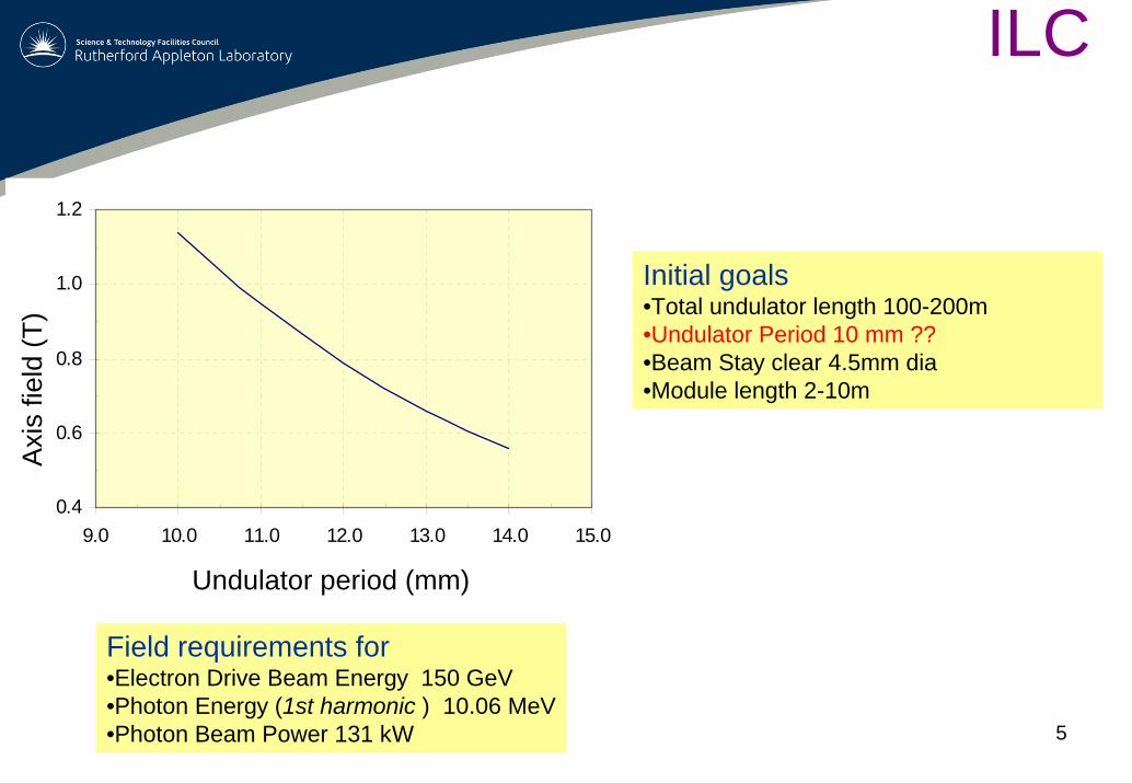
Undulator period (mm)
Initial goals•Total undulator length 100-200m•Undulator Period 10 mm ??•Beam Stay clear 4.5mm dia•Module length 2-10m
ILC
Field requirements for•Electron Drive Beam Energy 150 GeV•Photon Energy (1st harmonic ) 10.06 MeV•Photon Beam Power 131 kW
6
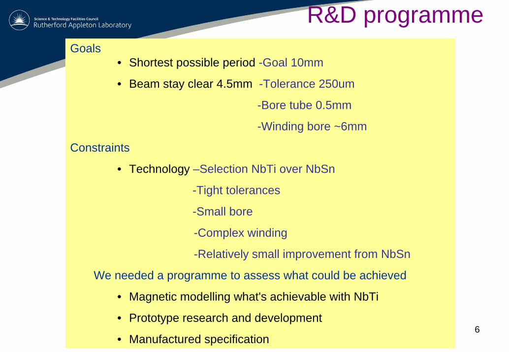
R&D programmeGoals
• Shortest possible period -Goal 10mm
• Beam stay clear 4.5mm -Tolerance 250um
-Bore tube 0.5mm
-Winding bore ~6mm
Constraints
• Technology –Selection NbTi over NbSn
-Tight tolerances
-Small bore
-Complex winding
-Relatively small improvement from NbSn
We needed a programme to assess what could be achieved
• Magnetic modelling what's achievable with NbTi
• Prototype research and development
• Manufactured specification
7
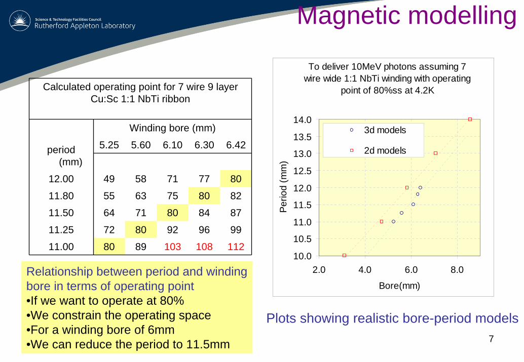
Calculated operating point for 7 wire 9 layerCu:Sc 1:1 NbTi ribbon
Winding bore (mm)
5.25 5.60 6.10 6.30 6.42period (mm)
12.00 49 58 71 77 80
11.80 55 63 75 80 82
11.50 64 71 80 84 87
11.25 72 80 92 96 99
11.00 80 89 103 108 112
Relationship between period and winding bore in terms of operating point•If we want to operate at 80%•We constrain the operating space•For a winding bore of 6mm•We can reduce the period to 11.5mm
Plots showing realistic bore-period models
To deliver 10MeV photons assuming 7 wire wide 1:1 NbTi winding with operating
point of 80%ss at 4.2K
10.0
10.5
11.0
11.5
12.0
12.5
13.0
13.5
14.0
2.0 4.0 6.0 8.0
Bore(mm)Pe
riod
(mm
)
3d models
2d models
Magnetic modelling
8
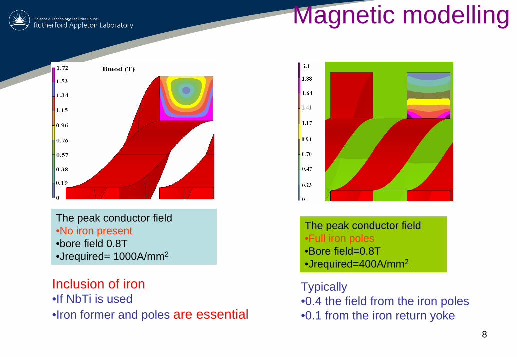
The peak conductor field •No iron present•bore field 0.8T•Jrequired= 1000A/mm2
The peak conductor field •Full iron poles•Bore field=0.8T•Jrequired=400A/mm2
Inclusion of iron•If NbTi is used •Iron former and poles are essential
Typically •0.4 the field from the iron poles•0.1 from the iron return yoke
Magnetic modelling
9
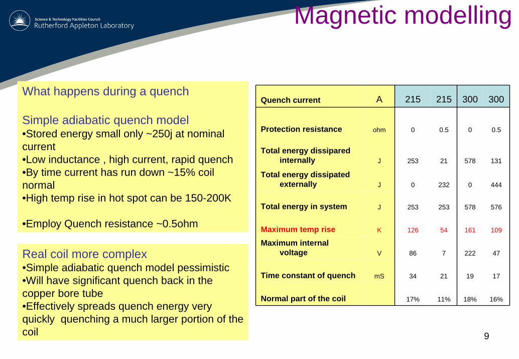
Quench current A 215 215 300 300
Protection resistance ohm 0 0.5 0 0.5
Total energy dissiparedinternally J 253 21 578 131
Total energy dissipated externally J 0 232 0 444
Total energy in system J 253 253 578 576
Maximum temp rise K 126 54 161 109
Maximum internal voltage V 86 7 222 47
Time constant of quench mS 34 21 19 17
Normal part of the coil 17% 11% 18% 16%
Real coil more complex•Simple adiabatic quench model pessimistic•Will have significant quench back in the copper bore tube•Effectively spreads quench energy very quickly quenching a much larger portion of the coil
Magnetic modelling
What happens during a quench
Simple adiabatic quench model•Stored energy small only ~250j at nominal current •Low inductance , high current, rapid quench•By time current has run down ~15% coil normal•High temp rise in hot spot can be 150-200K
•Employ Quench resistance ~0.5ohm
10
Prototype R&D
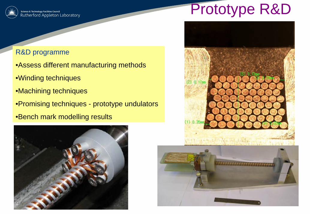
R&D programme
•Assess different manufacturing methods
•Winding techniques
•Machining techniques
•Promising techniques - prototype undulators
•Bench mark modelling results
11
Prototype R&D
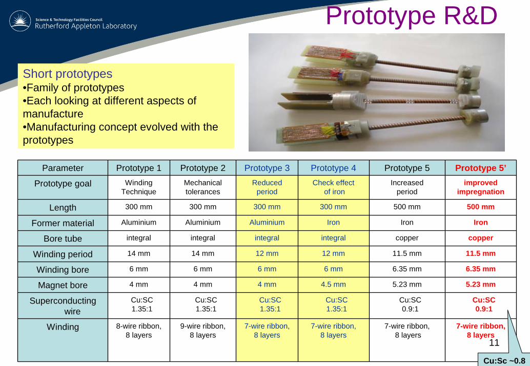
Parameter Prototype 1 Prototype 2 Prototype 3 Prototype 4 Prototype 5 Prototype 5’
Prototype goal Winding Technique
Mechanical tolerances
Reduced period
Check effectof iron
Increasedperiod
improved impregnation
Length 300 mm 300 mm 300 mm 300 mm 500 mm 500 mm
Former material Aluminium Aluminium Aluminium Iron Iron Iron
Bore tube integral integral integral integral copper copper
Winding period 14 mm 14 mm 12 mm 12 mm 11.5 mm 11.5 mm
Winding bore 6 mm 6 mm 6 mm 6 mm 6.35 mm 6.35 mm
Magnet bore 4 mm 4 mm 4 mm 4.5 mm 5.23 mm 5.23 mm
Superconducting wire
Cu:SC1.35:1
Cu:SC1.35:1
Cu:SC1.35:1
Cu:SC1.35:1
Cu:SC0.9:1
Cu:SC0.9:1
Winding 8-wire ribbon, 8 layers
9-wire ribbon, 8 layers
7-wire ribbon, 8 layers
7-wire ribbon, 8 layers
7-wire ribbon,8 layers
7-wire ribbon, 8 layers
Short prototypes•Family of prototypes•Each looking at different aspects of manufacture•Manufacturing concept evolved with the prototypes
Cu:Sc ~0.8
12
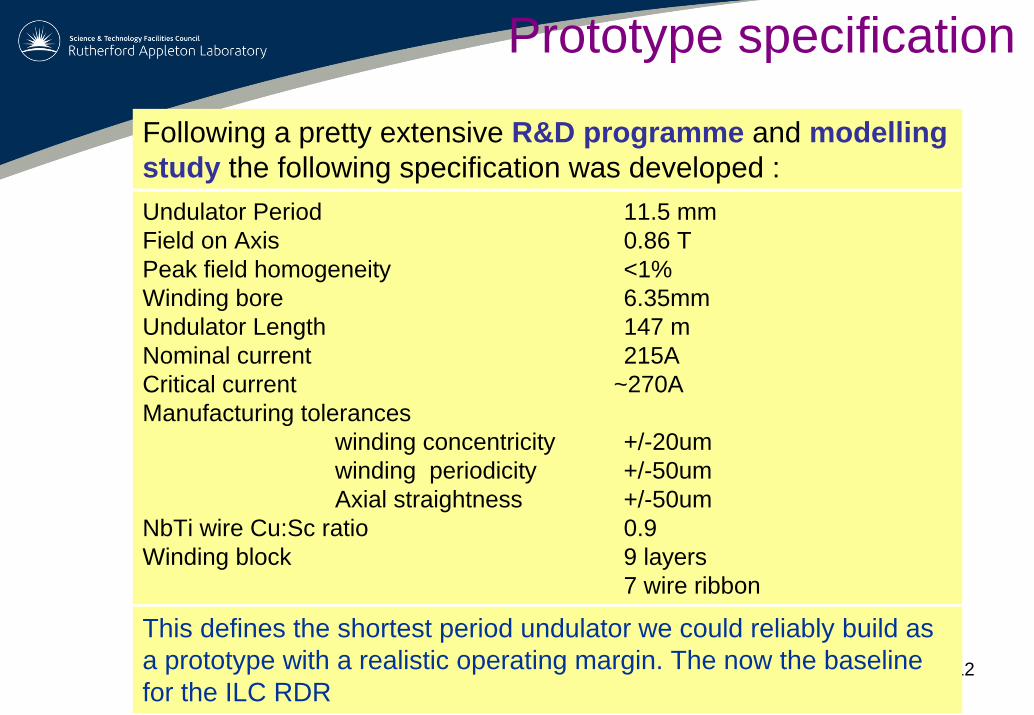
Following a pretty extensive R&D programme and modelling study the following specification was developed :Undulator Period 11.5 mm Field on Axis 0.86 TPeak field homogeneity <1%Winding bore 6.35mmUndulator Length 147 mNominal current 215ACritical current ~270A Manufacturing tolerances
winding concentricity +/-20umwinding periodicity +/-50umAxial straightness +/-50um
NbTi wire Cu:Sc ratio 0.9 Winding block 9 layers
7 wire ribbon
This defines the shortest period undulator we could reliably build as a prototype with a realistic operating margin. The now the baseline for the ILC RDR
Prototype specification
13
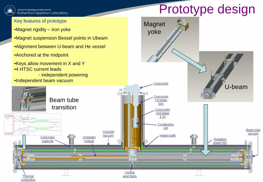
Key features of prototype
•Magnet rigidity – iron yoke
•Magnet suspension Bessel points in Ubeam
•Alignment between U-beam and He vessel
•Anchored at the midpoint
•Keys allow movement in X and Y•4 HTSC current leads
- independent powering•Independent beam vacuum
Prototype design
Beam tube transition
Magnet yoke
U-beam
14
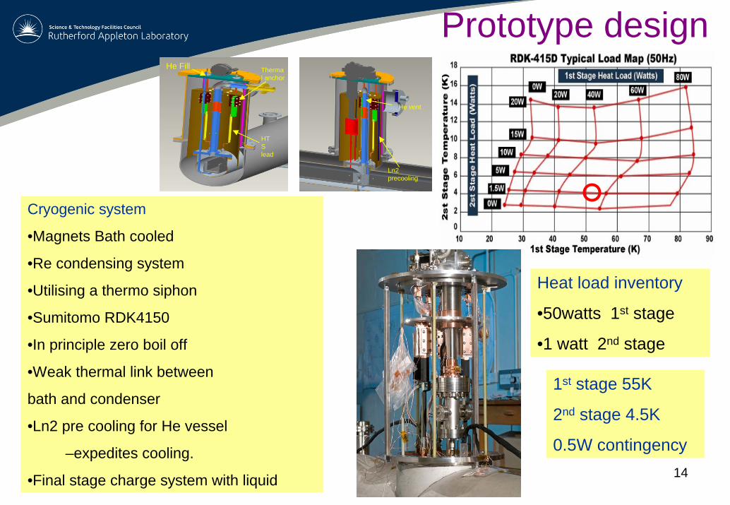
Cryogenic system
•Magnets Bath cooled
•Re condensing system
•Utilising a thermo siphon
•Sumitomo RDK4150
•In principle zero boil off
•Weak thermal link between
bath and condenser
•Ln2 pre cooling for He vessel
–expedites cooling.
•Final stage charge system with liquid
Heat load inventory
•50watts 1st stage
•1 watt 2nd stage
Prototype designHe Fill Therma
l anchor
HTS lead
Ln2 precooling
He vent
1st stage 55K
2nd stage 4.5K
0.5W contingency
15
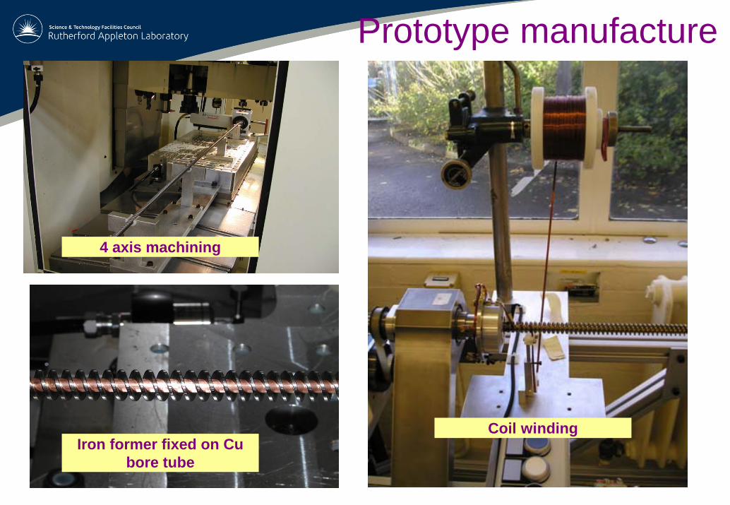
Iron former fixed on Cu bore tube
4 axis machining
Coil winding
Prototype manufacture
16
Prototype manufacture
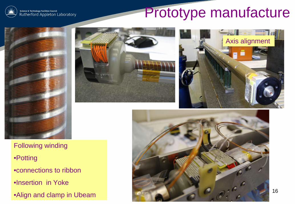
Following winding
•Potting
•connections to ribbon
•Insertion in Yoke
•Align and clamp in Ubeam
Axis alignment
17
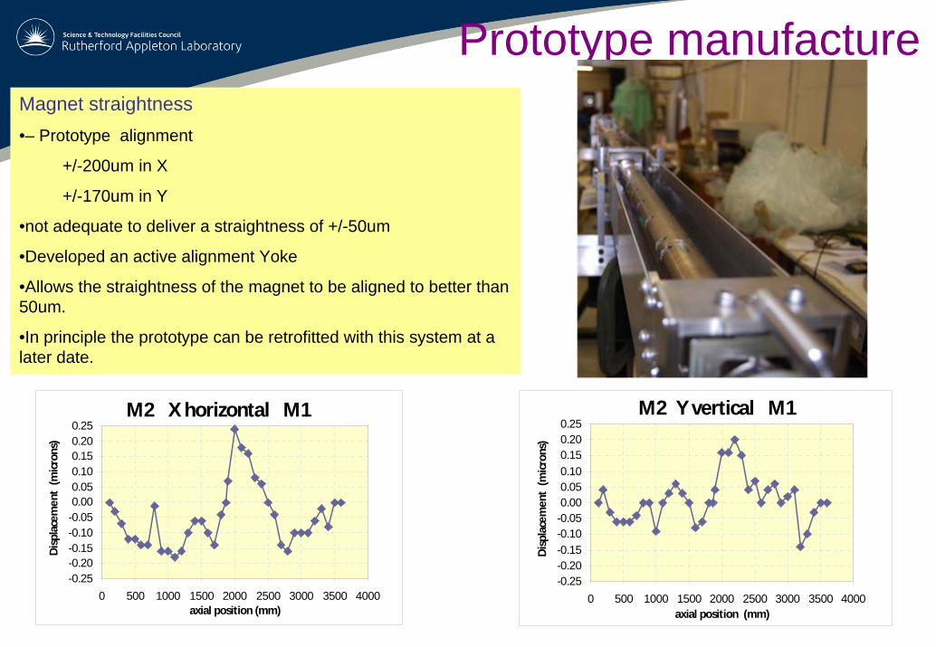
Magnet straightness•– Prototype alignment
+/-200um in X
+/-170um in Y
•not adequate to deliver a straightness of +/-50um
•Developed an active alignment Yoke
•Allows the straightness of the magnet to be aligned to better than 50um.
•In principle the prototype can be retrofitted with this system at a later date.
Prototype manufacture
M2 X horizontal M1
-0.25-0.20-0.15-0.10-0.050.000.050.100.150.200.25
0 500 1000 1500 2000 2500 3000 3500 4000axial position (mm)
Disp
lace
men
t (m
icron
s)
M2 Y vertical M1
-0.25-0.20-0.15-0.10-0.050.000.050.100.150.200.25
0 500 1000 1500 2000 2500 3000 3500 4000axial position (mm)
Disp
lace
men
t (m
icron
s)
18
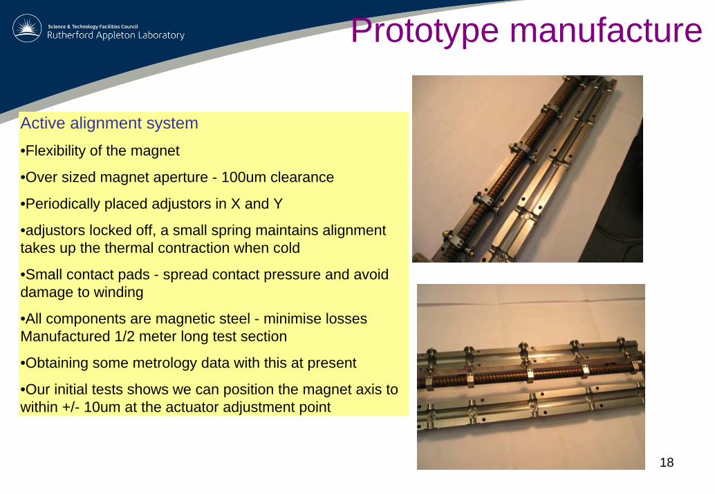
Active alignment system•Flexibility of the magnet
•Over sized magnet aperture - 100um clearance
•Periodically placed adjustors in X and Y
•adjustors locked off, a small spring maintains alignment takes up the thermal contraction when cold
•Small contact pads - spread contact pressure and avoid damage to winding
•All components are magnetic steel - minimise losses Manufactured 1/2 meter long test section
•Obtaining some metrology data with this at present
•Our initial tests shows we can position the magnet axis to within +/- 10um at the actuator adjustment point
Prototype manufacture
19
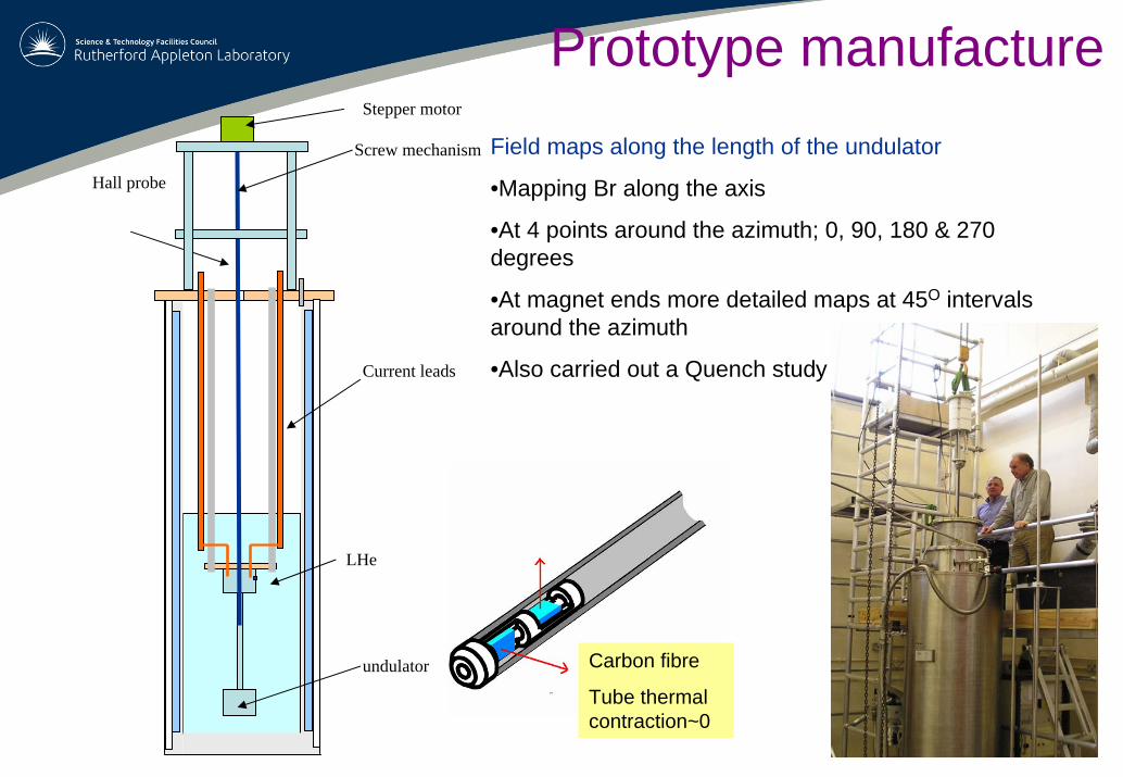
Field maps along the length of the undulator
•Mapping Br along the axis
•At 4 points around the azimuth; 0, 90, 180 & 270 degrees
•At magnet ends more detailed maps at 45O intervals around the azimuth
•Also carried out a Quench studyCurrent leads
LHe
Hall probe
undulator
Stepper motor
Screw mechanism
Carbon fibre
Tube thermal contraction~0
Prototype manufacture
20
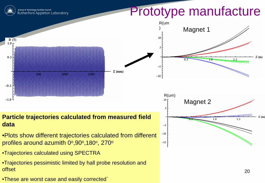
Prototype manufacture
Particle trajectories calculated from measured field data
•Plots show different trajectories calculated from different profiles around azumith 0o,90o,180o, 270o
•Trajectories calculated using SPECTRA
•Trajectories pessimistic limited by hall probe resolution and offset
•These are worst case and easily corrected`
R(um) Magnet 1
R(um)
Magnet 2
21
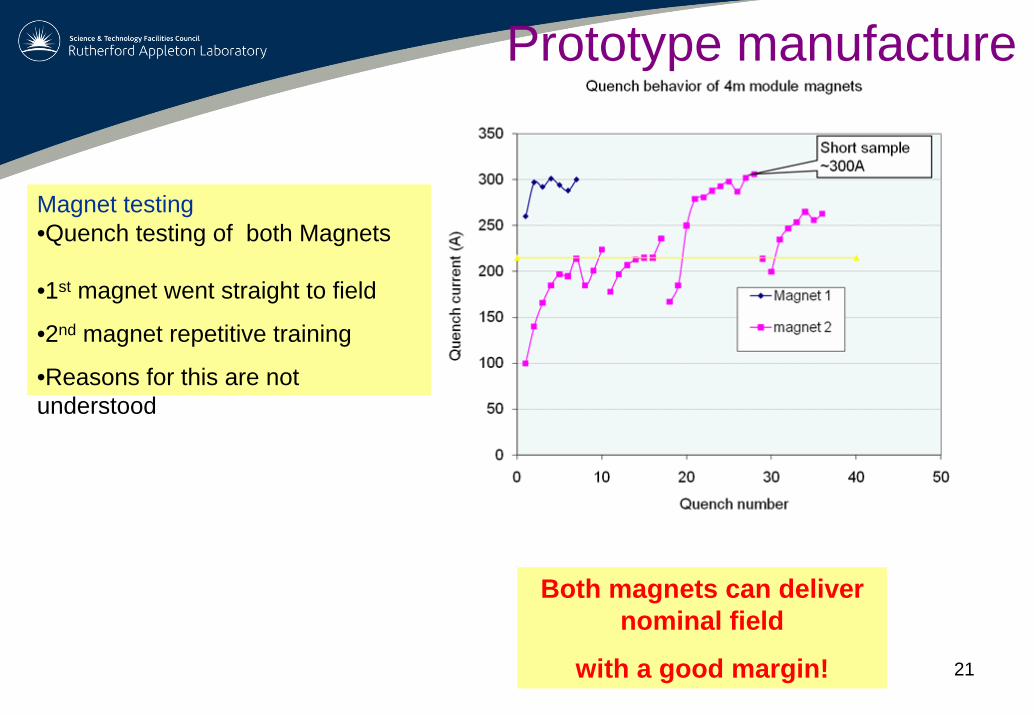
Magnet testing•Quench testing of both Magnets
•1st magnet went straight to field
•2nd magnet repetitive training
•Reasons for this are not understood
Both magnets can deliver nominal field
with a good margin!
Prototype manufacture
22
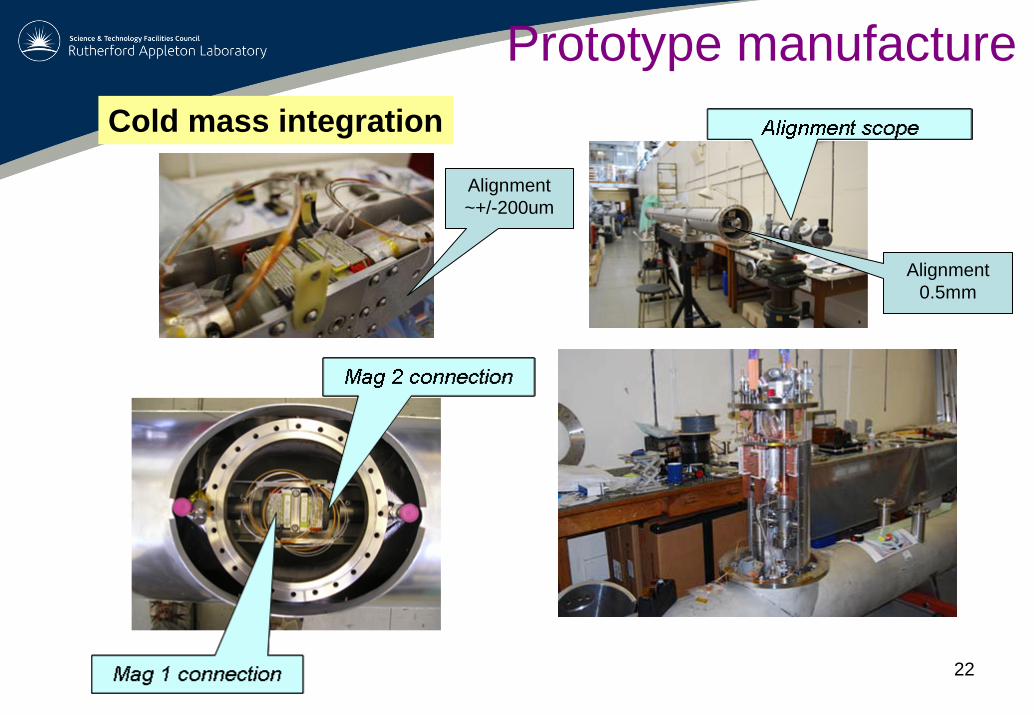
Prototype manufactureCold mass integration
Alignment ~+/-200um
Alignment 0.5mm
23
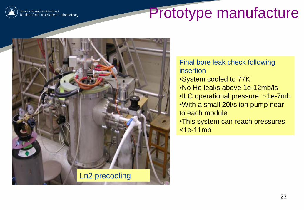
Prototype manufacture
Final bore leak check following insertion•System cooled to 77K•No He leaks above 1e-12mb/ls•ILC operational pressure ~1e-7mb•With a small 20l/s ion pump near to each module •This system can reach pressures <1e-11mb
Ln2 precooling
24
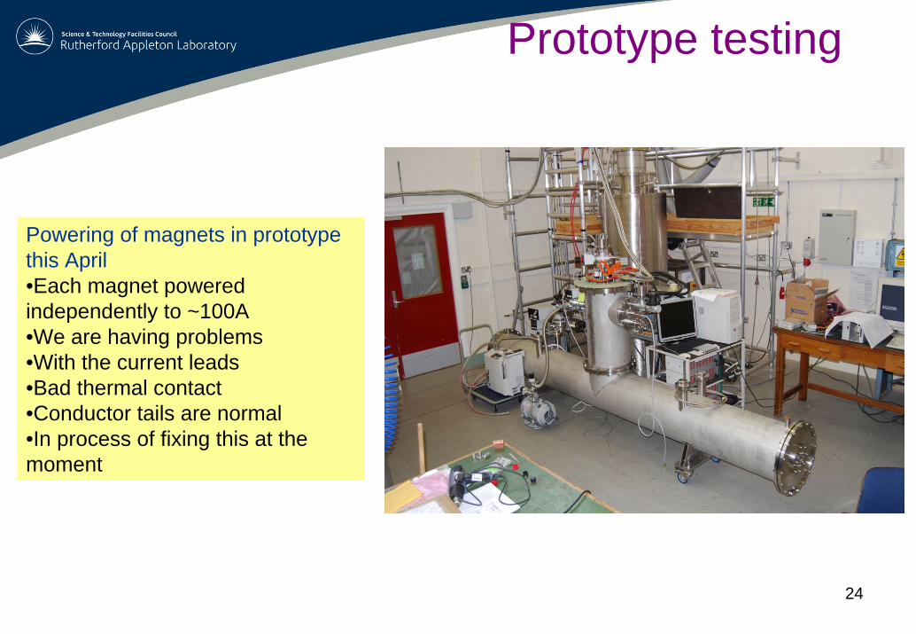
Prototype testing
Powering of magnets in prototype this April•Each magnet powered independently to ~100A•We are having problems•With the current leads•Bad thermal contact •Conductor tails are normal •In process of fixing this at the moment
25
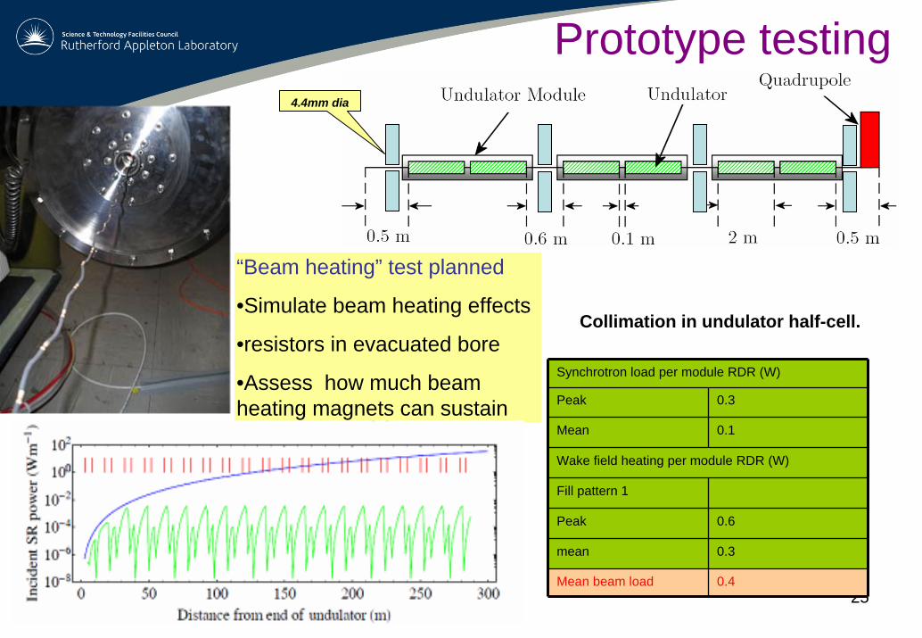
“Beam heating” test planned
•Simulate beam heating effects
•resistors in evacuated bore
•Assess how much beam heating magnets can sustain
Collimation in undulator half-cell.
Synchrotron load per module RDR (W)
Peak 0.3
Mean 0.1
Wake field heating per module RDR (W)
Fill pattern 1
Peak 0.6
mean 0.3
Mean beam load 0.4
Prototype testing4.4mm dia
26
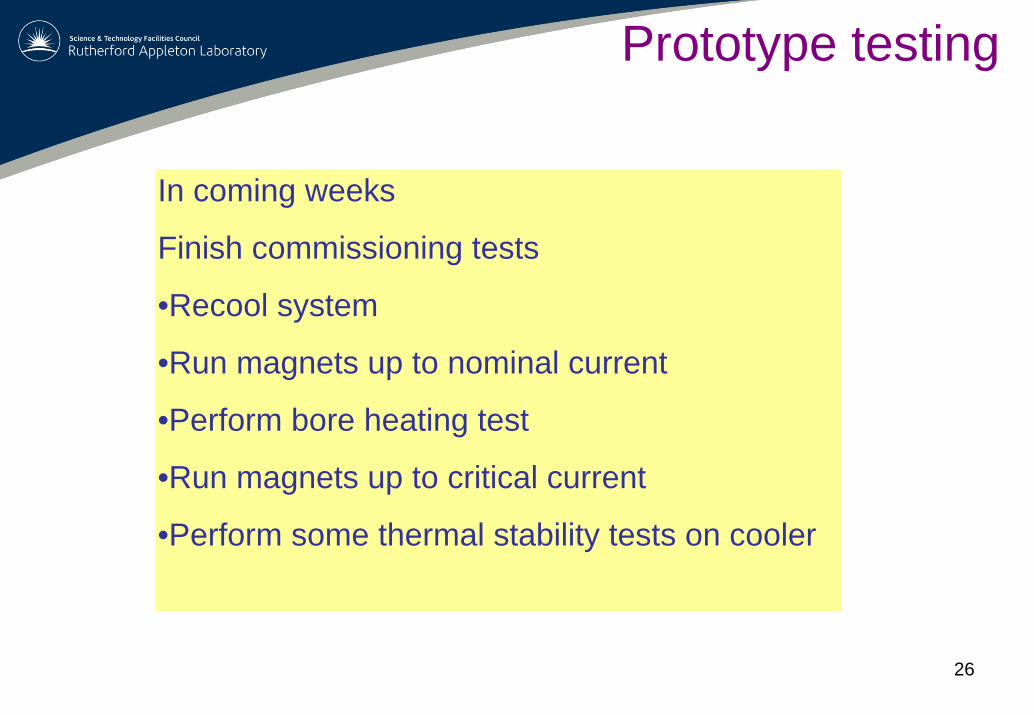
In coming weeks
Finish commissioning tests
•Recool system
•Run magnets up to nominal current
•Perform bore heating test
•Run magnets up to critical current
•Perform some thermal stability tests on cooler
Prototype testing
27
A prototype helical undulator has been built for the ILC
•The system is capable of fulfilling the ILC positron source requirements
•The magnets have demonstrated that they can meet thefield requirements
•They are now integrated in the final module
•The system is now being commissioned
•Tests to see how much beam heating the module can sustain are underway
Summary


![Stress Computation in the C400 Superconducting Coil Using ...accelconf.web.cern.ch/accelconf/PAC2009/papers/mo6pfp074.pdf · [2] M.N. Wilson, Superconducting Magnets , pub Oxford](https://img.pdfslide.us/doc/110x75/5ec37260d076c03bee637f0f/stress-computation-in-the-c400-superconducting-coil-using-2-mn-wilson-superconducting.jpg)