Embed Size (px)
Citation preview
▲275The Journal of The South African Institute of Mining and Metallurgy VOLUME 105 REFEREED PAPER APRIL 2005
Introduction
Instability in stope panels in near-surface andshallow mines manifests itself as rockfallsfrom the hangingwall. Rockfalls from unstablestope panels vary in size from rockfallsbetween support units, to rockfalls spanningbetween pillars or solid abutments, to rockfallsbridging several panels and pillars. The focusof this paper is major in-panel stability/instability i.e. what spans between pillars willbe stable given the geotechnical conditions.
Very few mines design stope panelsaccording to a systematic design procedure ormethodology. Rock mass characterization,estimation of rock mass properties, identifi-cation of potential failure modes, appropriatestability analyses and other elements of therock engineering design process are oftenneglected. Instead, panel lengths are oftendictated by the equipment in use and byprevious experience under similar conditions.Consequently, stope panel collapses oftenoccur on near-surface and shallow mines dueto their excessive panel lengths. Althoughthese incidents often occur during blasting,they pose a threat to the safety of undergroundworkers and to the economical extraction oforebodies. Hence, a methodology for the rockengineering design of stable stope panelsbetween pillars is of vital importance foroptimum safety and production in shallowmining operations.
This paper describes the factors governingthe stability/instability of stope panels in orderto define a suitable design methodology forshallow mining operations. Using thismethodology, rock mechanics practitioners andmine planners should be able to identify andquantify the critical factors influencing thestability of stope panels. The critical factorsshould then be used as input to the design ofstable stope panels that will provide thenecessary safe environment for undergroundpersonnel working in stopes.
Evaluation of rock engineering designmethods
The design methods that are available forassessing the stability of stope panels can bebroadly categorized as follows:
The design of stable stope spans forshallow mining operationsby A.H. Swart* and M.F. Handley†
Synopsis
Unplanned stope panel collapses occur on most near-surface andshallow mines in South Africa. Although these incidents often occurduring blasting, they pose a major threat to the safety ofunderground workers and the economic extraction of orebodies.Most stope panel collapses occur due to excessive panel lengths(resulting in excessive stope spans) that are not designed accordingto a systematic design procedure or methodology. Instead, panellengths are often dictated by the equipment in use and by previousexperience under similar conditions. Hence, a rock engineeringdesign methodology for the design of stable stope panels betweenpillars is of vital importance for optimum safety and production inshallow mining operations.
Using the proposed design methodology described in this paper,rock mechanics practitioners and mine planners should be able toidentify and quantify the critical factors influencing the stability ofstope panels. The critical factors should then be used as input to thedesign of stable stope panels that will provide the necessary safeenvironment for underground personnel working in stopes.
The proposed design methodology is an iterative process, whichincludes aspects such as rock mass characterization, estimation ofrock mass properties, identification of potential failure modes,consideration of appropriate stability analyses and other elementsof the rock engineering design process. This process continues afterimplementation. During monitoring, new data should be included inthe database and the design process repeated on a regular basis.Design approaches included in the proposed design methodologyinclude empirical methods such as different rock mass classificationmethods, analytical methods such as elastic and Voussoir beamanalyses, kinematic analyses, probabilistic analyses, and numericalanalyses.
Keywords: stability, stope panels, design methodology, hardrock mines, shallow mining operations
* SRK Consulting, Northlands, South Africa.† Rock Mechanics, University of Pretoria, South
Africa.© The South African Institute of Mining and
Metallurgy, 2005. SA ISSN 0038–223X/3.00 +0.00. This paper was first published at the SAIMMConference, Platinum Adding Value, 3–7 October2004.
The design of stable stope spans for shallow mining operations
➤ empirical methods➤ analytical methods➤ observational methods.
Empirical design methods
Empirical design can be defined as experienced-basedapplication of known performance levels. It is believed thatempirical design of stope spans is the most predominantdesign approach. Rock mass classification methods form theformal part, and engineering judgement based on experience,the informal part of empirical design of stope panels. Rockmass classifications relate practical experience gained onprevious projects to the conditions anticipated at a proposedsite. They are particularly useful in the planning andpreliminary design stages of a rock engineering project but,in some cases, they also serve as the main practical basis forthe design of complex underground structures.
Although rock mass classifications have provided asystematic design aid, modern rock mass classifications havenever been intended as the ultimate solution to designproblems, but only as a means towards this end. Accordingto Bieniawski1, modern rock mass classifications weredeveloped to create some order out of the chaos in siteinvestigation procedures and to provide the desperatelyneeded design aids. They were not intended to replaceanalytical studies, field observations and measurements, norengineering judgement. Hence, rock mass classificationshould be used in conjunction with observational methodsand analytical studies to formulate an overall designrationale compatible with the design objectives and sitegeology.
Of the rock mass classification systems reviewed bySwart et al.2, four systems could be considered for evaluatingthe stability of stope spans. These systems are:
➤ The Geomechanics classification or rock mass rating(RMR) system developed by Bieniawski3
➤ The Norwegian Geotechnical Institute (NGI), rockquality index or Q-system developed by Barton et al.4.
➤ The mining rock mass classification or modified rockmass rating (MRMR) system originally developed byLaubscher5. This system is a modification of the RMRsystem
➤ The modified stability graph method through the use ofthe modified stability number, N’, originally developedby Mathews et al.6.
The geomechanics classification system
Bieniawski’s1 rock mass rating classification (RMR89) is thesystem that is most frequently used today. Over the yearssince the first publication, the system has benefited fromextensions and applications by many authors throughout theworld and has stood the test of time. The varied applicationspoint to the acceptance of the system and its inherent ease ofuse and versatility.
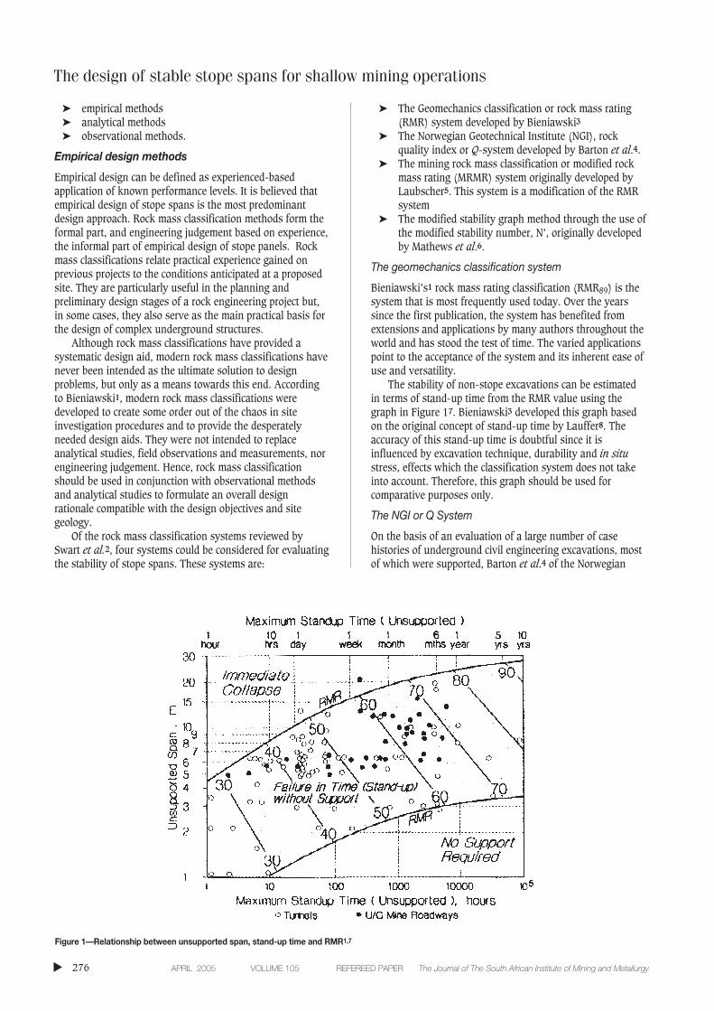
The stability of non-stope excavations can be estimatedin terms of stand-up time from the RMR value using thegraph in Figure 17. Bieniawski3 developed this graph basedon the original concept of stand-up time by Lauffer8. Theaccuracy of this stand-up time is doubtful since it isinfluenced by excavation technique, durability and in situstress, effects which the classification system does not takeinto account. Therefore, this graph should be used forcomparative purposes only.
The NGI or Q System
On the basis of an evaluation of a large number of casehistories of underground civil engineering excavations, mostof which were supported, Barton et al.4 of the Norwegian
▲
276 APRIL 2005 VOLUME 105 REFEREED PAPER The Journal of The South African Institute of Mining and Metallurgy
Figure 1—Relationship between unsupported span, stand-up time and RMR1,7
Geotechnical Institute (NGI) proposed the Q- system rockmass classification for the determination of rock masscharacteristics and tunnel support requirements.
According to Barton et al.4, the maximum unsupportedspan can be estimated from the following equation:
where: ESR (excavation support ratio) is a value that isassigned to an excavation in terms of the degree of securitythat is demanded of the installed support system to maintainthe stability of the excavation. Hutchinson and Diederichs9
recommend that an ESR of not more than 3 be used fortemporary mine openings.
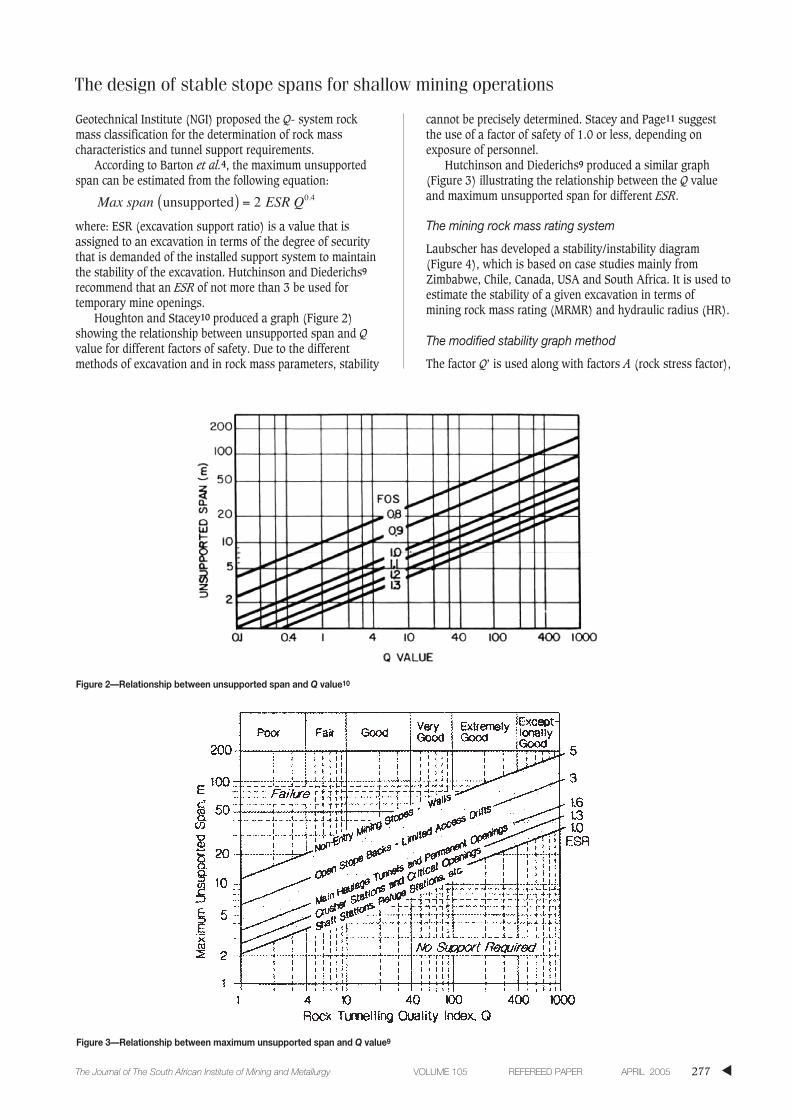
Houghton and Stacey10 produced a graph (Figure 2)showing the relationship between unsupported span and Qvalue for different factors of safety. Due to the differentmethods of excavation and in rock mass parameters, stability
cannot be precisely determined. Stacey and Page11 suggestthe use of a factor of safety of 1.0 or less, depending onexposure of personnel.
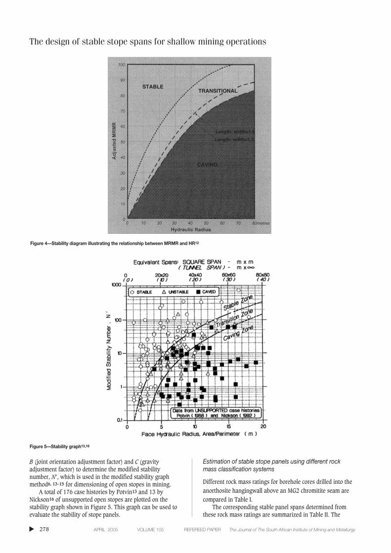
Hutchinson and Diederichs9 produced a similar graph(Figure 3) illustrating the relationship between the Q valueand maximum unsupported span for different ESR.
The mining rock mass rating system
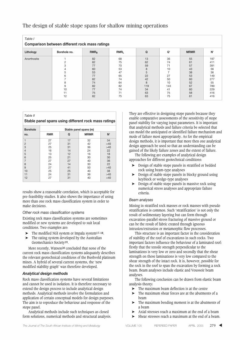
Laubscher has developed a stability/instability diagram(Figure 4), which is based on case studies mainly fromZimbabwe, Chile, Canada, USA and South Africa. It is used toestimate the stability of a given excavation in terms ofmining rock mass rating (MRMR) and hydraulic radius (HR).
The modified stability graph method
The factor Q’ is used along with factors A (rock stress factor),
Max span ESR Q unsupported ( ) = 2 0 4.
The design of stable stope spans for shallow mining operations
▲277The Journal of The South African Institute of Mining and Metallurgy VOLUME 105 REFEREED PAPER APRIL 2005
Figure 2—Relationship between unsupported span and Q value10
Figure 3—Relationship between maximum unsupported span and Q value9
The design of stable stope spans for shallow mining operations
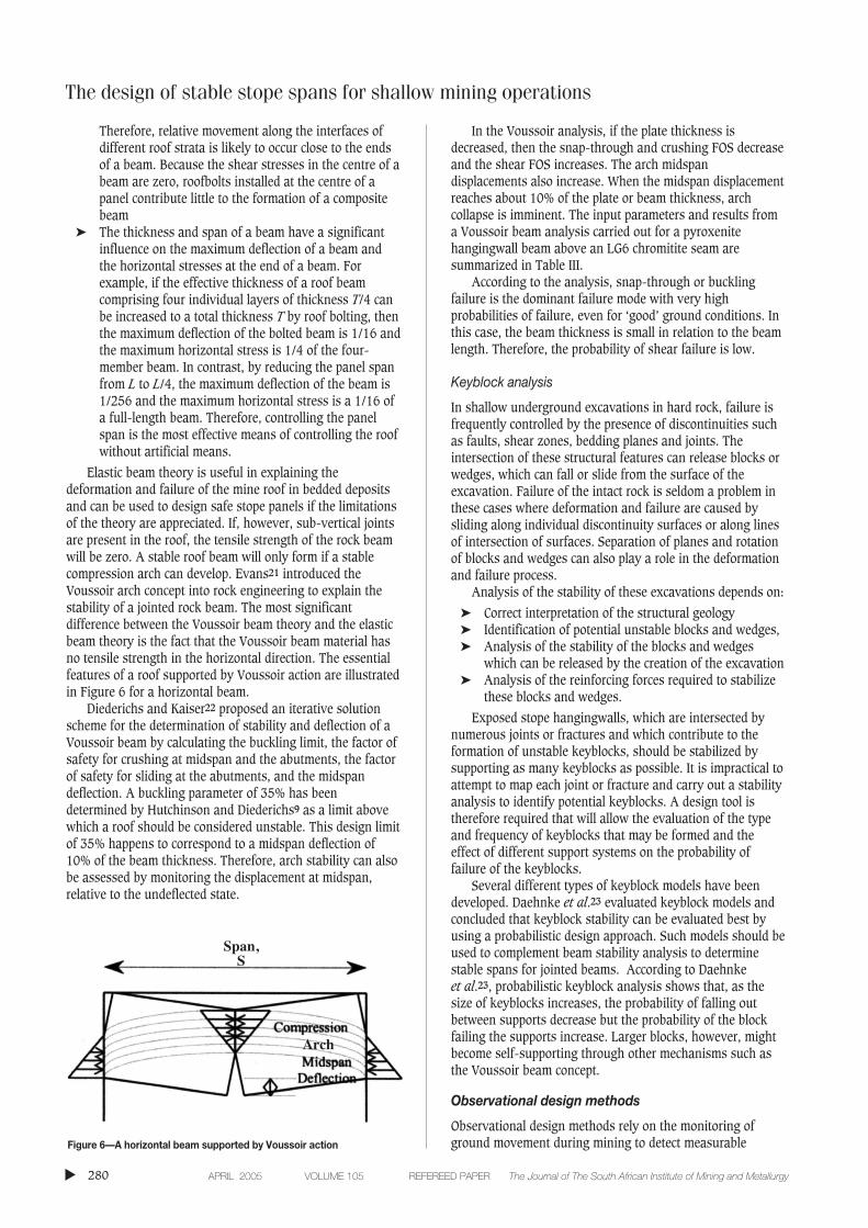
B (joint orientation adjustment factor) and C (gravityadjustment factor) to determine the modified stabilitynumber, N’, which is used in the modified stability graphmethod6, 13–15 for dimensioning of open stopes in mining.
A total of 176 case histories by Potvin13 and 13 byNickson16 of unsupported open stopes are plotted on thestability graph shown in Figure 5. This graph can be used toevaluate the stability of stope panels.
Estimation of stable stope panels using different rockmass classification systems
Different rock mass ratings for borehole cores drilled into theanorthosite hangingwall above an MG2 chromitite seam arecompared in Table I.
The corresponding stable panel spans determined fromthese rock mass ratings are summarized in Table II. The
▲
278 APRIL 2005 VOLUME 105 REFEREED PAPER The Journal of The South African Institute of Mining and Metallurgy
Figure 4—Stability diagram illustrating the relationship between MRMR and HR12
Figure 5—Stability graph13,16
STABLETRANSITIONAL
CAVING
Length: width>1.5
Length: width<1.3
results show a reasonable correlation, which is acceptable forpre-feasibility studies. It also shows the importance of usingmore than one rock mass classification system in order tomake decisions.
Other rock mass classification systemsExisting rock mass classification systems are sometimesmodified or new systems are developed to suit localconditions. Two examples are:
➤ The modified NGI system or Impala system17–18.➤ The rating system developed by the Australian
Geomechanics Society19.
More recently, Watson20 concluded that none of thecurrent rock mass classification systems adequately describesthe relevant geotechnical conditions of the Bushveld platinummines. A hybrid of several current systems, the ‘newmodified stability graph’ was therefore developed.
Analytical design methodsRock mass classification systems have several limitationsand cannot be used in isolation. It is therefore necessary toextend the design process to include analytical designmethods. Analytical methods involve the formulation andapplication of certain conceptual models for design purposes.The aim is to reproduce the behaviour and response of thestope panel.
Analytical methods include such techniques as closedform solutions, numerical methods and structural analysis.
They are effective in designing stope panels because theyenable comparative assessments of the sensitivity of stopepanel stability for varying input parameters. It is importantthat analytical methods and failure criteria be selected thatcan model the anticipated or identified failure mechanism andmode of failure most appropriately. As for the empiricaldesign methods, it is important that more then one analyticaldesign approach be used so that an understanding can begained of the likely failure zones and the extent of failure.
The following are examples of analytical designapproaches for different geotechnical conditions:
➤ Design of stable stope panels in stratified or beddedrock using beam-type analyses
➤ Design of stable stope panels in blocky ground usingkeyblock or wedge-type analyses
➤ Design of stable stope panels in massive rock usingnumerical stress analyses and appropriate failurecriteria.
Beam analysesMining in stratified rock masses or rock masses with pseudostratification is common. Such ‘stratification’ is not only theresult of sedimentary layering but can form throughexcavation-parallel stress fracturing of massive ground orcan be the result of fabric created through igneousintrusion/extrusion or metamorphic flow processes.
This structure is an important factor in the considerationof stability of the roof of excavations in such rocks. Twoimportant factors influence the behaviour of a laminated roof:firstly that the tensile strength perpendicular to thelaminations is very low or zero and secondly that the shearstrength on these laminations is very low compared to theshear strength of the intact rock. It is, however, possible forthe rock in the roof to span the excavation by forming a rockbeam. Beam analyses include elastic and Voussoir beamanalyses.
The following conclusion can be drawn from elastic beamanalysis theory:
➤ The maximum beam deflection is at the centre➤ The maximum shear forces are at the abutments of a
beam➤ The maximum bending moment is at the abutments of
a beam➤ Axial stresses reach a maximum at the end of a beam➤ Shear stresses reach a maximum at the end of a beam.
The design of stable stope spans for shallow mining operations
▲279The Journal of The South African Institute of Mining and Metallurgy VOLUME 105 REFEREED PAPER APRIL 2005
Table I
Comparison between different rock mass ratings
Lithology Borehole no. RMRB RMRL Q Q' MRMR N'
Anorthosite 1 82 68 13 36 55 1972 82 75 62 74 61 4113 77 70 59 71 57 3914 60 53 8 10 43 565 53 47 5 7 38 366 77 65 22 27 53 1497 82 74 42 50 60 2778 74 64 8 10 52 559 82 82 119 143 67 78910 77 74 34 41 60 22911 75 71 63 75 58 41612 82 75 63 75 61 416
Table II
Stable panel spans using different rock mass ratings
Borehole Stable panel spans (m)
no. RMR Q MRMR N'
1 27 17 32 342 27 31 42 >403 25 31 36 >404 16 14 24 225 13 12 16 186 25 21 30 307 27 27 40 368 24 14 30 229 27 41 50 >4010 25 25 40 3811 24 31 36 >4012 27 31 40 >40
The design of stable stope spans for shallow mining operations
Therefore, relative movement along the interfaces ofdifferent roof strata is likely to occur close to the endsof a beam. Because the shear stresses in the centre of abeam are zero, roofbolts installed at the centre of apanel contribute little to the formation of a compositebeam
➤ The thickness and span of a beam have a significantinfluence on the maximum deflection of a beam andthe horizontal stresses at the end of a beam. Forexample, if the effective thickness of a roof beamcomprising four individual layers of thickness T/4 canbe increased to a total thickness T by roof bolting, thenthe maximum deflection of the bolted beam is 1/16 andthe maximum horizontal stress is 1/4 of the four-member beam. In contrast, by reducing the panel spanfrom L to L/4, the maximum deflection of the beam is1/256 and the maximum horizontal stress is a 1/16 ofa full-length beam. Therefore, controlling the panelspan is the most effective means of controlling the roofwithout artificial means.
Elastic beam theory is useful in explaining thedeformation and failure of the mine roof in bedded depositsand can be used to design safe stope panels if the limitationsof the theory are appreciated. If, however, sub-vertical jointsare present in the roof, the tensile strength of the rock beamwill be zero. A stable roof beam will only form if a stablecompression arch can develop. Evans21 introduced theVoussoir arch concept into rock engineering to explain thestability of a jointed rock beam. The most significantdifference between the Voussoir beam theory and the elasticbeam theory is the fact that the Voussoir beam material hasno tensile strength in the horizontal direction. The essentialfeatures of a roof supported by Voussoir action are illustratedin Figure 6 for a horizontal beam.
Diederichs and Kaiser22 proposed an iterative solutionscheme for the determination of stability and deflection of aVoussoir beam by calculating the buckling limit, the factor ofsafety for crushing at midspan and the abutments, the factorof safety for sliding at the abutments, and the midspandeflection. A buckling parameter of 35% has beendetermined by Hutchinson and Diederichs9 as a limit abovewhich a roof should be considered unstable. This design limitof 35% happens to correspond to a midspan deflection of10% of the beam thickness. Therefore, arch stability can alsobe assessed by monitoring the displacement at midspan,relative to the undeflected state.
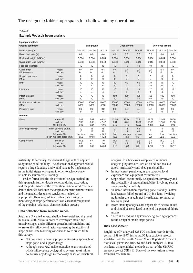
In the Voussoir analysis, if the plate thickness isdecreased, then the snap-through and crushing FOS decreaseand the shear FOS increases. The arch midspandisplacements also increase. When the midspan displacementreaches about 10% of the plate or beam thickness, archcollapse is imminent. The input parameters and results froma Voussoir beam analysis carried out for a pyroxenitehangingwall beam above an LG6 chromitite seam aresummarized in Table III.
According to the analysis, snap-through or bucklingfailure is the dominant failure mode with very highprobabilities of failure, even for ‘good’ ground conditions. Inthis case, the beam thickness is small in relation to the beamlength. Therefore, the probability of shear failure is low.
Keyblock analysis
In shallow underground excavations in hard rock, failure isfrequently controlled by the presence of discontinuities suchas faults, shear zones, bedding planes and joints. Theintersection of these structural features can release blocks orwedges, which can fall or slide from the surface of theexcavation. Failure of the intact rock is seldom a problem inthese cases where deformation and failure are caused bysliding along individual discontinuity surfaces or along linesof intersection of surfaces. Separation of planes and rotationof blocks and wedges can also play a role in the deformationand failure process.
Analysis of the stability of these excavations depends on:
➤ Correct interpretation of the structural geology➤ Identification of potential unstable blocks and wedges,➤ Analysis of the stability of the blocks and wedges
which can be released by the creation of the excavation➤ Analysis of the reinforcing forces required to stabilize
these blocks and wedges.
Exposed stope hangingwalls, which are intersected bynumerous joints or fractures and which contribute to theformation of unstable keyblocks, should be stabilized bysupporting as many keyblocks as possible. It is impractical toattempt to map each joint or fracture and carry out a stabilityanalysis to identify potential keyblocks. A design tool istherefore required that will allow the evaluation of the typeand frequency of keyblocks that may be formed and theeffect of different support systems on the probability offailure of the keyblocks.
Several different types of keyblock models have beendeveloped. Daehnke et al.23 evaluated keyblock models andconcluded that keyblock stability can be evaluated best byusing a probabilistic design approach. Such models should beused to complement beam stability analysis to determinestable spans for jointed beams. According to Daehnke et al.23, probabilistic keyblock analysis shows that, as thesize of keyblocks increases, the probability of falling outbetween supports decrease but the probability of the blockfailing the supports increase. Larger blocks, however, mightbecome self-supporting through other mechanisms such asthe Voussoir beam concept.
Observational design methods
Observational design methods rely on the monitoring ofground movement during mining to detect measurable
▲
280 APRIL 2005 VOLUME 105 REFEREED PAPER The Journal of The South African Institute of Mining and Metallurgy
Figure 6—A horizontal beam supported by Voussoir action
Span,S
Arch
instability. If necessary, the original design is then adjustedto optimize panel stability. The observational approach wouldrequire a large database and would have to be implementedin the initial stages of stoping in order to achieve somereliable measurement of stability.
Peck24 formalized the observational design method. Inthis approach, further data is collected during excavation,and the performance of the excavation is monitored. The newdata is then fed back into the original characterization resultsand the models, designs or conclusions revised asappropriate. Therefore, adding further data during themonitoring of stope performance is an essential componentof the ongoing rock mass characterization process.
Data collection from selected mines
Swart et al.2 visited several shallow base metal and diamondmines in South Africa in order to investigate stable andunstable stopes under different geotechnical conditions andto assess the influence of factors governing the stability ofstope panels. The following conclusions were drawn fromthis survey:
➤ Not one mine is using a proper engineering approach tostope panel and support design
➤ Although most FOG incidents/accidents are associatedwhich failure along geological structures, most minesdo not use any design methodology based on structural
analysis. In a few cases, complicated numericalanalysis programs are used on an ad hoc basis toassess structurally controlled panel stability
➤ In most cases, panel lengths are based on localexperience and equipment requirements
➤ Stope pillars are normally designed conservatively andthe probability of regional instability, involving severalstope panels, is unlikely
➤ Valuable information regarding panel stability is oftenlost because fall of ground (FOG) incidents involvingno injuries are usually not investigated, recorded, orback-analysed
➤ Beam stability analyses are applicable to several minesand should be considered as one of the potential failuremodes
➤ There is a need for a systematic engineering approachto the design of stable stope panels.
Risk assessment
Joughin et al.25 analysed 328 FOG accident records for theperiod 1988 to 1997, including 55 fatal accident recordsavailable from the South African Mines Reportable AccidentStatistics System (SAMRASS) and back-analysed 42 fatalaccidents using empirical methods as part of the SIMRACresearch project OTH 411. Some of the conclusions drawnfrom this research are:
The design of stable stope spans for shallow mining operations
▲281The Journal of The South African Institute of Mining and Metallurgy VOLUME 105 REFEREED PAPER APRIL 2005
Table III
Example Voussoir beam analysis
Input parameters:Ground conditions Bad ground Good ground Very good ground
Panel spans (m) 28 x 15 28 x 20 28 x 28 28 x 15 28 x 20 28 x 28 28 x 15 28 x 20 28 x 28
Beam thickness (m) 0.8 0.8 0.8 0.8 0.8 0.8 0.8 0.8 0.8
Rock unit weight (MN/m3) 0.034 0.034 0.034 0.034 0.034 0.034 0.034 0.034 0.034
Overburden load (MN/m3) 0.043 0.043 0.043 0.043 0.043 0.043 0.043 0.043 0.043
Face dip (degrees) 10 10 10 10 10 10 10 10 10
Overburden mean 0.4 0.4 0.4 0.4 0.4 0.4 0.4 0.4 0.4thickness (m) std. dev. 0.1 0.1 0.1 0.1 0.1 0.1 0.1 0.1 0.1
Support pressure mean 0 0 0 0 0 0 0 0 0(MPa) std. dev. 0 0 0 0 0 0 0 0 0
RMR mean 40 40 40 60 60 60 70 70 70std. dev. 20 20 20 20 20 20 20 20 20
Intact (m) mean 10 10 10 13 13 13 17 17 17std. dev. 4 4 4 4 4 4 4 4 4
Intact strength mean 70 70 70 100 100 100 130 130 130(MPa) std. dev. 40 40 40 40 40 40 40 40 40
Rock mass modulus mean 10000 10000 10000 30000 30000 30000 40000 40000 40000(MPa) std. dev. 5000 5000 5000 20000 20000 20000 20000 20000 20000
Poisson's ratio mean 0.2 0.2 0.2 0.2 0.2 0.2 0.2 0.2 0.2std. dev. 0 0 0 0 0 0 0 0 0
Results:
shear mean SF 5.09 5.04 46.31 12.25 12.24 50.21 22.07 21.49 20.58std. dev. 2.96 3.05 47.42 6.91 6.61 44.28 13.93 12.51 11.13
fail. prob. (%) 8.36 9.27 16.96 5.18 4.46 13.32 6.52 5.08 3.93
Arch snap-through mean buckling param. 10 41 78 2 14 54 0 4 22std. dev. 10 28 22 2 14 46 0 4 18
fail. prob. (%) medium high v. high low medium v. high low low mediummean midspan displ. (mm) 37.2 108.3 140.3 16.5 41.9 36.1 9.1 22.8 63.9
Compression mean SF 11.5 6.4 1.9 17.4 11.1 9.3 23 15.2 3.9std. dev. 6.8 4.1 2.6 7.2 4.7 3.2 7.5 5 4.5
fail. prob. (%) 6.01 9.37 35.59 1.17 1.63 0.51 0.16 0.22 26.17
The design of stable stope spans for shallow mining operations
➤ The average injury and fatality rates on some smallermines were significantly higher than on the largermines
➤ Although more injuries and fatalities occurred on thelarger mines, some smaller mines had almost as many,and sometimes even more injuries and fatalities thanthe larger mines
➤ The injury and fatality rates for mines with tabularorebodies were significantly higher than for mines withother orebodies
➤ The most common forms of failure were wedges,blocky hangingwalls and weak hangingwalls
➤ Only 10 per cent of rocks had dimensions greater than5.9 m x 2.8 m x 1.2 m
➤ In most of the fatal FOG accidents, support standardswere inadequate or no support standards existed. Thiscould be attributed to the lack of rock engineeringinvolvement and the fact that support standards areoften compiled by mine management with very littleunderstanding of the geotechnical conditions of therock mass.
Joughin et al.25 found that, even after analysing theaccident information stored in SAMRASS, and all theavailable fatal accident reports for falls of ground, root causeswere still difficult to identify and suggested that the fault-event tree methodology to risk assessment be used toidentify significant hazards and quantify the significantrisks. Swart et al.2 assessed the significant risks associatedwith stope panel stability during two one-day workshops.The risk assessment was based on the fault-event treeanalysis technique. First, the significant hazards associatedwith stope panel collapses were identified using theinformation obtained from a literature survey, site visits andpersonal experience. The significant hazards were thenanalysed systematically to form a cause tree. Probabilities ofoccurrences were then allocated on a judgemental basis toform a fault tree.
The significant hazards identified can be grouped into thefollowing main categories:
➤ Inadequate rock wall strength due to in situ rock massconditions
➤ Inadequate rock wall strength due to adverse geometry(size, shape, orientation, location)
➤ Inadequate support strength➤ Adverse loading conditions.
Considering the significant hazards identified in the riskassessment, it is important that an engineering approach tostope panel design be followed. Such an approach shouldinclude aspects such as:
➤ Rock mass characterization➤ Estimation of rock mass properties➤ Identification of potential failure modes➤ Appropriate stability analyses.
Rock engineerng design methodology
Bieniawski26 distinguishes between the following ten stagesin the design process:
➤ Recognition of a need or a problem➤ Statement of the problem➤ Collection of information
➤ Concept formulation in accordance with design criteria:search for a method, theory, model, or hypothesis
➤ Analysis of solution components➤ Synthesis to create a detailed solution➤ Evaluation and testing of the solution➤ Optimization➤ Recommendation➤ Communication➤ Implementation.
Stacey and Page11 suggested that the following approachto underground excavation design be followed:
➤ Determine shape and size of excavation based on thepurpose of the excavation. In the case of stoping, theshape and size will be determined by the orebodygeometry and the chosen mining method
➤ Consider an ‘ideal’ excavation, which best satisfies thepurpose
➤ Consider the practicality of this ‘ideal’ opening inrelation to the properties of the rock mass in which itwill be located
➤ Ascertain the stability of the ‘ideal’ excavation by:- determining the mode of any identified instability- test for stress induced failure around opening- test for instability of large blocks- classify the rock mass and test for rock mass
instability.➤ If necessary, optimize ‘ideal’ excavation in terms of
size, shape, orientation or location in order toovercome instability. (Loop back to (3) if anygeometrical changes are made)
➤ If modified excavation is still unstable, determinesupport required to overcome instability. (Appropriatesupport will depend on the risk associated with anexcavation.)
Brown27 listed the following components of a generalizedprogramme for underground excavation design:
➤ Site characterization➤ Geotechnical model formulation➤ Design analysis➤ Rock mass performance monitoring➤ Retrospective analysis.
Proposed design methodology for stable stopepanels
From the above, it is concluded that the design of stablestope panels should be a process of defining the means ofcreating stable stope panels for the safety of undergroundworkers and optimum extraction of the orebody. Therefore, amethod is required whereby all rock properties, theirvariability, and an understanding of all rock mechanismsaffecting the stability of stope spans are used as afundamental base. A procedure for identifying themechanisms and rock properties relevant to the specificproblem is then required. In this way, existing knowledgeshould be used in an optimal way to design site-specificstable stope spans.
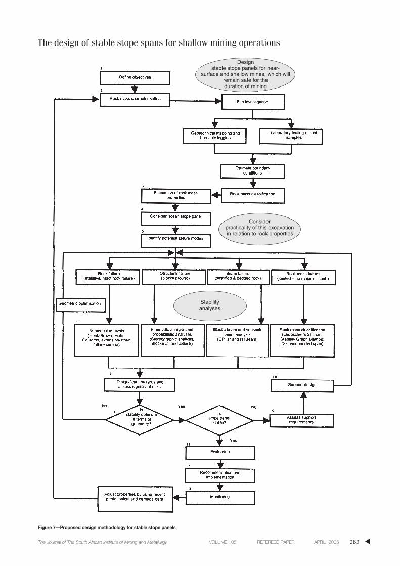
Hence, it is proposed that the design methodologyillustrated in Figure 7 be used for the design of stable stopepanels. It is important to note that it is an iterative processwith feedback loops that test/evaluate the design aspectssuch as:
▲
282 APRIL 2005 VOLUME 105 REFEREED PAPER The Journal of The South African Institute of Mining and Metallurgy
The design of stable stope spans for shallow mining operations
▲283The Journal of The South African Institute of Mining and Metallurgy VOLUME 105 REFEREED PAPER APRIL 2005
Figure 7—Proposed design methodology for stable stope panels
Designstable stope panels for near-
surface and shallow mines, which willremain safe for the duration of mining
Considerpracticality of this excavationin relation to rock properties
Stabilityanalyses
The design of stable stope spans for shallow mining operations
➤ Design assumptions/premise➤ Design objectives/desired outcomes➤ The acceptability of the risk (i.e. are the significant
risks tolerable?)
Rock mass characterization
The roof or hangingwall of stope panels must be charac-terized in order to:
➤ Define the rock mass condition➤ Evaluate the rock mass strength and deformation
behaviour➤ Identify the most likely modes of potential rock mass
failure➤ Determine the most appropriate method of stability
analysis or design➤ Define geotechnical areas➤ Define rock mass properties➤ Evaluate the stability of the rock mass➤ Evaluate the support requirements of the excavation.
The following steps are required to characterize the rockmass in the roof of stope panels:
➤ Collection of geotechnical data➤ Evaluation or estimation of the boundary conditions➤ Rock mass classification➤ Recording and presentation of geotechnical data.
Collection of geotechnical data
The collection of sufficient and reliable geotechnical dataforms the basis on which the rock mass will be characterizedand is essential for the design of stable stope panels. Thisinformation represents the independent variables that cannotbe controlled by the design engineer. The source of potentialgeotechnical data and the extent of the existing geotechnicaldatabase depend on the stage of the investigation (pre-feasibility, feasibility preliminary design or final designstage).
Geotechnical data should be obtained through:
➤ Site investigations➤ Geotechnical drilling and logging of borehole core➤ Mapping of exposed rock surfaces➤ Laboratory testing of rock samples
Evaluation or estimation of boundary conditions
In situ stresses determine the confinement imposed on therock mass and are an essential boundary condition for theevaluation of stability. They can have the following effects onstability:
➤ Instability may occur if the stress is low since rockblocks may have the freedom to fall out
➤ The rock mass will be well confined and stable if thestress is higher
➤ Instability may occur due to rock fracturing if the stresslevel is sufficiently high.
Stress measurements using an overcoring technique,small flat jacks or hydrofracturing is expensive and timeconsuming. It is therefore suggested that in situ stressconditions be estimated based on the work carried out byStacey and Wesseloo28.
Rock mass classification
Rock mass classification can be used for the design of stablestope panels. In essence, rock mass classification relatespractical experience gained on previous projects to theconditions anticipated at a proposed site. It is particularlyuseful in the planning and preliminary design stages of arock engineering project but, in some cases, it also serve asthe main practical basis for the design of complexunderground structures.
To derive input properties for further analyses, dataobtained from underground mapping, logging of boreholecore and laboratory tests should be rated according to anappropriate rock mass classification system. It is suggestedthat at least two rock mass classification systems be used toobtain a picture of the rock mass fracturing, the character-istics of the fractures (planarity, roughness, infilling andcontinuity) and the location of major, continuous faultstructures. The average and range of the rock mass classifi-cation values (e.g. Q and RMR) should be determined as ameans of estimating the variability of the quality of each rocktype.
Recording and presentation of geotechnical data
Geotechnical data collected must be recorded and presentedsuch that it will be readily available and easily understood.This could include presentation of:
➤ Borehole data in well-executed geotechnical logs➤ Mapping data as spherical projections➤ Relevant geological and geotechnical data for rock
mass classification purposes➤ Longitudinal sections and cross-sections of structural
geology➤ Construction of a geotechnical domain model.
Estimation of rock mass properties
It is extremely important that the quality of input datamatches the sophistication of the design methods. It is,however, almost impossible to perform controlled laboratorytests on large, jointed rock samples. Therefore, estimates ofthe strength and stiffness properties are typically made byusing rock mass classification in combination with laboratorydetermination of intact rock strength.
The following rock mass properties can be estimated fromthe rock mass classification data:
➤ Hoek and Brown m and s parameters➤ Young’s Modulus, E.
Consider ‘ideal’ excavation
The geometry of an ‘ideal’ excavation is typically controlledby factors such as:
➤ Drilling equipment➤ Cleaning equipment➤ Scheduling➤ Full constraints➤ Labour and equipment efficiencies➤ Orebody dimensions.
▲
284 APRIL 2005 VOLUME 105 REFEREED PAPER The Journal of The South African Institute of Mining and Metallurgy
Identification of potential failure modes
The following failure modes should be considered:
➤ Structurally controlled, gravity-driven failures➤ Stress induced, gravity-assisted failures.
Stability analyses
Appropriate analyses should be carried out to assess thestability of the ‘ideal’ excavation. Wedge and block failuretypes could be analyse using analysis programs such asJBlock29. Beam failure types should be analysed using theVoussoir beam analysis procedure proposed by Hutchinsonand Diedericks9 or programs such as CPillar or NTBeam.
Identification of significant hazards and assessmentof significant risks
All significant hazards should be identified using anappropriate risk assessment methodology. Care must betaken to ensure that the hazards are identified systemat-ically. Significant hazards/risks should then be eliminated orreduced to acceptable limits by optimizing the geometry,installing support, etc.
Geometrical optimization
If stability analyses show that the assumed ‘ideal’ stopepanel is unstable, or the support required to ensure stabilityis either unpractical or uneconomical, the ‘ideal’ stope panelmust be optimized by considering one or more of thefollowing geometrical changes:
➤ Location➤ Orientation➤ Shape➤ Size.
Evaluation of support requirements
Most ‘ideal’ stope panels, even when optimized in terms ofgeometry, are inherently unstable and require support toimprove the strength or capacity of the rock mass such that itwill remain stable and safe, at least during extraction of thepanel, and as long as access is required through the panel.
Appropriate support will depend on the risk associatedwith the excavation. Therefore, although the probability ofrockfalls occurring could be high, the risk of rockfallaccidents could be minimized by minimizing entry to thestope panel.
At the same time, a database and damage maps shouldbe developed to identify the location and mechanisms offailure in the mine. These failures should be back-analysedusing appropriate failure models and criteria in order toprevent a reoccurrence.
Roof supports are used to help stabilize undergroundopenings. Their performance characteristics must be properlymatched to the loading environment and ground behaviour ifthey are to succeed.
The key characteristics of any support includes itsmaximum load carrying capacity, stiffness, and residualstrength. Other important factors are timing of installation,
the stability of the support as it is loaded, and the capabilityof the support system to provide skin control.
Evaluation of ideas and solutions
The solution proposed must now be interpreted andcompared with the original objectives. This calls for a clearunderstanding of all pertinent interacting factors; that is, forthe exercise of engineering judgement. If the evaluationshows up deficiencies or suggests more promisingalternatives, loop back to the stability analysis stage.
Optimization
Optimize the ‘ideal’ opening with respect to location,orientation, shape and size. If any geometrical changes aremade, loop back to Stage 4.
Conclusions and recommendations
Provide a concise statement of the answer to the problem,point out the limitations or restrictions and indicate thedirection to be followed in implementing the solution.
Monitoring
Monitor performance and take remedial measures in case ofinstability.
Conclusions
The following general conclusions could be drawn:
➤ Most mines do not use proper engineering approachesto stope panel and support design
➤ Although most FOG incidents/accidents are associatedwith failure along geological structures, most mines donot use any design methodology based on structuralanalysis. In a few cases, complicated numericalanalysis programs are used on an ad hoc basis toassess structurally controlled panel stability
➤ In most cases, panel lengths are based on localexperience and equipment requirements
➤ Valuable information regarding panel stability is oftenlost because FOG incidents are not investigated,recorded or back-analysed
➤ Beam stability analyses are applicable to several minesand should be considered as one of the potential failuremodes
➤ There is a need for a systematic engineering approachto the design of stable stope panels
➤ Rock mass classification forms an integral part of stopepanel design. Although it cannot be used directly forstability analysis purposes, it should be used toestimate rock mass properties required for analyticaldesigns.
Recommendations
➤ More than one rock mass classification method andanalytical design approach should be used to assessground conditions and to carry out stability analyses
The design of stable stope spans for shallow mining operations
▲285The Journal of The South African Institute of Mining and Metallurgy VOLUME 105 REFEREED PAPER APRIL 2005
The design of stable stope spans for shallow mining operations
➤ A systematic design approach should be followed todesign stable stope panels
➤ Analytical methods and failure criteria should be usedthat can model the anticipated or identified failuremechanism and mode of failure most accurately
➤ All failure modes should be considered during stopepanel design. This also applies to FOG investigationswhere hangingwall failures are often described interms of ‘blocky’ and ‘weak’ only. Beam failure modes(buckling, shear and crushing failure) should beincluded
➤ The Voussoir beam analysis technique has been usedsuccessfully in other countries and should beconsidered for stope panel designs in stratified rock
➤ The proposed design methodology should be usedduring all stages of the mining process, from pre-feasibility to final design and implementation, andwhen compiling codes of practice to combat rockfallaccidents.
References
1. BIENIAWSKI, Z.T. Engineering Rock Mass Classifications. John Wiley and
Sons, Inc., New York, 1989.
2. SWART, A.H., STACEY, T.R., WESSELOO, J., JOUGHIN, W.C., LE ROUX. K.,
WALKER, D., and BUTCHER, R. Investigation of factors governing the
stability/instability of stope panels in order to define a suitable design
methodology for near surface and shallow mining operations. SIMRAC
Project Report OTH501, 2000.
3. BIENIAWSKI, Z.T. Engineering Classification of Jointed Rock Masses. Trans
S. Afr. Inst. Civ. Engrs, vol. 15, 1973. pp. 335–344.
4. BARTON, N., LIEN, R., and LUNDE, J. Engineering classification of rock
masses for the design of tunnel support. Rock Mech., vol. 6, no. 4, 1974.
pp. 189–236,
5. LAUBSCHER, D.H. Geomechanics classification of jointed rock masses—
mining applications. Trans. Instn. Min. Metall. vol. 86, 1977, pp. A 1–8.
6. MATHEWS, K.E., HOEK, E., WYLLIE, D.C., and STEWART, S.B.V. Prediction of
stable excavtion for mining at depth below 1000 m in hard rock. CANMET
Report. DSS Serial No. OSQ80-00081, DSS File No. 17SQ.23440-0-9020.
Ottawa: Dept. Energy, Mines and Resources, 1981.
7. BIENIAWSKI, Z.T. Classification of rock masses for engineering: The RMR
system and future trends. Comprehensive Rock Engineering, Hudson
(ed.), Oxford, Pergamon, vol. 3, 1993. pp. 553–573.
8. LAUFFER, H. Gebirgsklassifizierung für den Stollenbau. Geol. Bauwesen
vol. 24, no. 1,1958. pp. 46–51.
9. HUTCHINSON, J.D. and DIEDERICHS, M.S. Cablebolting in Underground Mines,
BiTech Publishers Ltd, Richmond, Canada, 401 p, 1996.
10. HOUGHTON, D.A. and STACEY, T.R. Application of probability techniques to
underground situations, Proc. 7th Regional Conf. for Africa on Soil Mech.
and Foundation Engineering, Accra, 1980, vol. 2, A.A. Balkema,
pp. 879–883.
11. STACEY, T.R. and PAGE, C.H. Practical Handbook for Underground Rock
Mechanics. Clausthal-Zellerfeld: Trans Tech Publications, 1986. 144 pp.
12. LAUBSCHER, D.H. Planning mass mining operations. Comprehensive Rock
Engineering: Principles, Practice and Projects Hudson (ed.), Oxford,
Pergamon Press vol. 2, 1993, pp. 547–583.
13. POTVIN, Y. Empirical Open Stope Design in Canada. PhD thesis, Dept.
Mining and Mineral Processing, University of British Columbia, 1988.
14. BAWDEN, W.F. The use of rock mechanics principles in Canadian
underground hard rock mine design. Comprehensive Rock Engineering:
Principles, Practice and Projects Hudson (ed.), Oxford, Pergamon Press
vol. 5, 1993, pp. 247–290.
15. HOEK E., KAISER P.K., and BAWDEN W.F. Support of Underground
Excavations in Hard Rock. Rotterdam: Balkema, 1995.
16. NICKSON, S.D. Cable Support Guidelines for Underground Hard Rock Mine
Operations. Unpublished MSc. Thesis, Dept. Mining and Mineral
Processing, University of British Columbia, 1992. 223 pp.
17. WATSON, B.P. and NOBLE, K.R. Comparison between geotechnical areas on
the Bushveld Complex platinum mines, to identify critical spans and
suitable in-panel support. Proceedings of the 1st Southern African Rock
Engineering Symposium (SARES 97), Johannesburg, 1997, pp. 440–451.
18. HARTMAN, W. and HANDLEY, M.F. The application of the Q Tunnelling
Quality Index to rock mass assesssment at Impala Platinum Mine. Jour. S.
Afr. Inst. Min. and Metall., vol. 102, no. 3, April 2003, pp. 155–165.
19. PELLS, P.J.N., BEST, R.J. and POULOS, H.G. Design of roof support of the
Sydney Opera House underground parking station. Tunnelling and
Underground Space Technology. vol. 9, no. 2, pp. 201–207, 1994.
20. WATSON, B.P. A rock mass rating system for evaluating stope stability on
the Bushveld Platinum Mines. Jour. S.Afr. Inst. Min. Metall., vol. 104
no.4, May 2004, 2004. pp. 229–238.
21. EVANS, W.H. The strength of undermined strata. Institute of Mining and
Metallurgy, 1941, pp. 475–532.
22. DIEDERICHS, M.S. and KAISER, P.K. Stability of large excavations in
laminated hard rock masses: the Voussoir analogue revisited. Int. J. of
Rock Mech. and Mining Sciences, vol. 36, 1999, pp. 97–117.
23. DAEHNKE, A., ANDERSON, L.M., DE BEER, D., and ESTERHUIZEN, G.S. Stope face
support systems. SIMRAC Project Report GAP 330. Pretoria: Department
of Minerals and Energy, 1998.
24. PECK R.B. The observational method in applied soil mechanics. 9th
Rankine Lecture, Geotechnique, vol. 19,1969. pp. 171–187.
25. JOUGHIN, W.C., SWART, A.H., and STACEY, T.R. Review of fall of ground
problems in underground diamond mines and other mines with massive
orebodies and make recommendations on research needs to reduce fall of
ground casualties, particularly in the face area. SIMRAC Report OTH 411.
Pretoria, Department of Minerals and Energy, 1998.
26. BIENIAWSKI, Z.T. Rock mechanics design in mining and tunnelling.
Rotterdam: Balkema, 1984. p. 272.
27. BROWN, E.T. From theory to practice in rock engineering. Trans. Institution
of Mining and Metallurgy, London, vol. 94, 1985. pp. A67–A83.
28. STACEY, T.R. and WESSELOO, J. Evaluation and upgrading of records of
stress measurement data in the mining industry. SIMRAC Report GAP
511. Pretoria, Department of Minerals and Energy. 1998.
29. ESTERHUIZEN, G.S. JBlock User’s Manual and Technical Reference.
University of Pretoria, 1996. ◆
▲
286 APRIL 2005 VOLUME 105 REFEREED PAPER The Journal of The South African Institute of Mining and Metallurgy