Embed Size (px)
Citation preview
University of Liverpool Dept. Electrical and Electronic Engineering
The 1-hour Electric Broomstick Guitar
Liverpool Physics Teacher Conference 06/07/2017
Dr Kai Hoettges [email protected]
The 1-hour electric broomstick guitar This project is meant to be a quick demonstration of electromagnetics as well as practising the use of test equipment. It was designed as a fun way to approach electromagnetics from an interesting and maybe unusual angle. All key parts are easily available at low cost making it easy to reproduce and extend the experiments in a school setting.
Quick run through theory. A current flowing through a conductor will induce a magnetic field around the inductor. In a DC current that field is stable. In an AC current the magnetic field varies over time. Winding a wire into a coil, means that the field from all winding overlaps and adds up to a stronger field. Electromagnets are made from coils of wires. While an electric current follows the path of least conductance, magnetic field follow the path of least reluctance. Ferromagnetic materials such as iron have a low reluctance and are therefore often used as cores for electromagnets since they focus the electric field in the core of the coil. Conversely, if a varying magnetic field crosses a conductor it will induce a current. Again, winding the conductor into a coil will increase the resulting current. In principle, this can be used to construct simple generators where a permanent magnet is rotated past a coil to induce a current. However, this principle can also be used for measurement applications. To generate a moving magnetic field is not necessary to move the magnet or the coil. If a coil is wrapped around a permanent magnet, the coil will only experience a static field so no current is induced. If, however a ferromagnetic material in moved close to the magnet, it will distort the magnetic field locally and field lines move across the coil – a current is induced. This principle is used for several measurement applications. One common one is a tacho generator that is used to measure the speed in cars. A steel gear is attached to the main driveshaft so it rotates in sync with the wheels. As a tooth of the gear moves past the sensor it induces a small current – one pulse per tooth – the number of pulses is proportional to the speed of the car. We will look at the second major application in this experiment. The electric guitar pickup. Electric guitars do not pick up the sound of the string with a microphone (as in acoustic guitars). The vibration of the guitar string is picked up directly by an electromagnetic sensor – the ‘pickup’.
Guitar pickups consist of a series of permanent magnets (one for each string) wrapped in a (single) coil. Electric guitar strings are wrapped in steel or nickel wire (both ferromagnetic). If the string vibrates above the magnet, it will induce a current in the coil that is representative of the vibration of the string. If the coil is connected to a high input impedance amplifier (like guitar amplifier) we can measure a voltage signal cross the coil and amplify it. The voltage we pick up depends mostly on two parameters: - The strength of the magnetic field - The number of turns of the coil There are trade-offs around both parameter that limit how far they can be extended. A stronger magnet achieves a higher signal amplitude (voltage), but magnets are bulky, increase weight of the guitar and might simply not fit in the small space available for the pickup. A strong magnet will also attract the string and attenuate (dampen) the vibrating string and thereby affect the ‘sound’ of a guitar. Increasing the number of windings on the coil will also increase the signal amplitude. However, electrically the coil acts as an inductor and the impedance of an inductor increases with signal frequency. So, the coil will dampen high frequency signals and at some stage suppress them completely. The exact performance depends on the resistance of the wire and the number of turns. In most cases guitar pickups have between 5000 and 8000 windings. The lower end will not supress frequencies within the range of human hearing significantly but adding more turns and the pickup will supress high frequency components of the instrument. This again will affect the ‘sound’ of a guitar and may be done on purpose. In our workshop, we will build a very simple single string guitar pickup as a simple experiment that could be easily reproduced in schools and can be extended to allow the students to explore the topic at great depth by experimenting with variations of the pickup. We use a simple neodymium button magnet and a screw as a coil core. Ideally the coil should be wrapped around the magnet, however strong bar magnets are relatively expensive. Using a steel screw as an extended core means a smaller magnet can be used. It also allows to change the magnet to investigate how the pickup behaves with magnets of different strength.
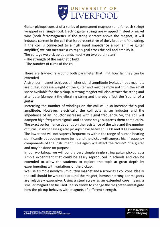
Button magnets have the poles at the opposite flat faces and the field stretches round the magnet in a ‘doughnut’ shape
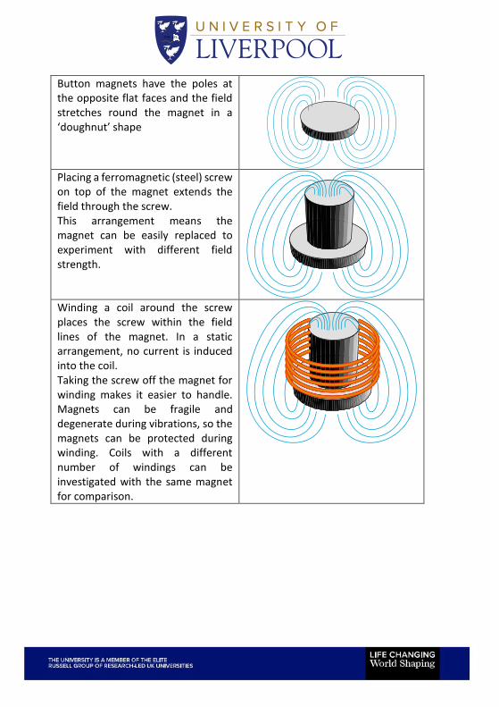
Placing a ferromagnetic (steel) screw on top of the magnet extends the field through the screw. This arrangement means the magnet can be easily replaced to experiment with different field strength.
Winding a coil around the screw places the screw within the field lines of the magnet. In a static arrangement, no current is induced into the coil. Taking the screw off the magnet for winding makes it easier to handle. Magnets can be fragile and degenerate during vibrations, so the magnets can be protected during winding. Coils with a different number of windings can be investigated with the same magnet for comparison.
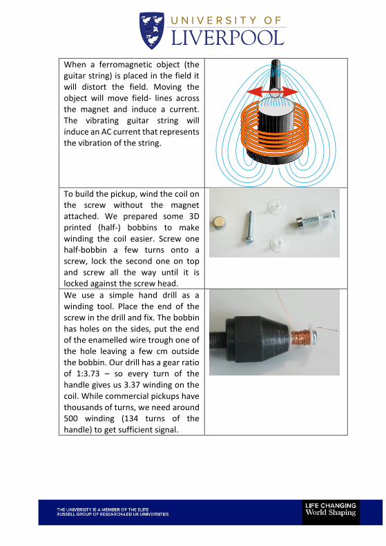
When a ferromagnetic object (the guitar string) is placed in the field it will distort the field. Moving the object will move field- lines across the magnet and induce a current. The vibrating guitar string will induce an AC current that represents the vibration of the string.
To build the pickup, wind the coil on the screw without the magnet attached. We prepared some 3D printed (half-) bobbins to make winding the coil easier. Screw one half-bobbin a few turns onto a screw, lock the second one on top and screw all the way until it is locked against the screw head.
We use a simple hand drill as a winding tool. Place the end of the screw in the drill and fix. The bobbin has holes on the sides, put the end of the enamelled wire trough one of the hole leaving a few cm outside the bobbin. Our drill has a gear ratio of 1:3.73 – so every turn of the handle gives us 3.37 winding on the coil. While commercial pickups have thousands of turns, we need around 500 winding (134 turns of the handle) to get sufficient signal.
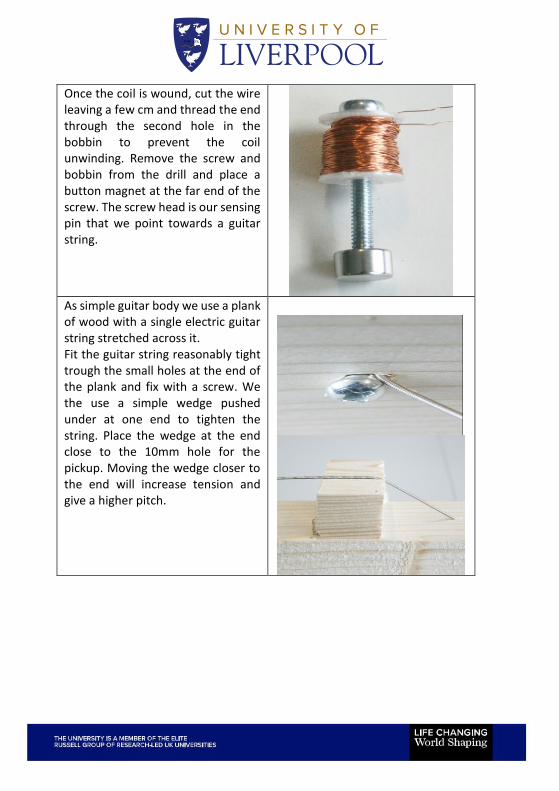
Once the coil is wound, cut the wire leaving a few cm and thread the end through the second hole in the bobbin to prevent the coil unwinding. Remove the screw and bobbin from the drill and place a button magnet at the far end of the screw. The screw head is our sensing pin that we point towards a guitar string.
As simple guitar body we use a plank of wood with a single electric guitar string stretched across it. Fit the guitar string reasonably tight trough the small holes at the end of the plank and fix with a screw. We the use a simple wedge pushed under at one end to tighten the string. Place the wedge at the end close to the 10mm hole for the pickup. Moving the wedge closer to the end will increase tension and give a higher pitch.
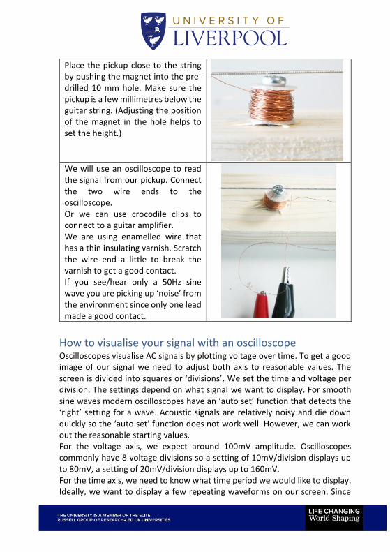
Place the pickup close to the string by pushing the magnet into the pre-drilled 10 mm hole. Make sure the pickup is a few millimetres below the guitar string. (Adjusting the position of the magnet in the hole helps to set the height.)
We will use an oscilloscope to read the signal from our pickup. Connect the two wire ends to the oscilloscope. Or we can use crocodile clips to connect to a guitar amplifier. We are using enamelled wire that has a thin insulating varnish. Scratch the wire end a little to break the varnish to get a good contact. If you see/hear only a 50Hz sine wave you are picking up ‘noise’ from the environment since only one lead made a good contact.
How to visualise your signal with an oscilloscope Oscilloscopes visualise AC signals by plotting voltage over time. To get a good image of our signal we need to adjust both axis to reasonable values. The screen is divided into squares or ‘divisions’. We set the time and voltage per division. The settings depend on what signal we want to display. For smooth sine waves modern oscilloscopes have an ‘auto set’ function that detects the ‘right’ setting for a wave. Acoustic signals are relatively noisy and die down quickly so the ‘auto set’ function does not work well. However, we can work out the reasonable starting values. For the voltage axis, we expect around 100mV amplitude. Oscilloscopes commonly have 8 voltage divisions so a setting of 10mV/division displays up to 80mV, a setting of 20mV/division displays up to 160mV. For the time axis, we need to know what time period we would like to display. Ideally, we want to display a few repeating waveforms on our screen. Since
we know what notes the guitar strings play, we can look up the frequencies and therefore calculate the period of the notes
String Note Frequency Period
1 E 330Hz 3.03ms
2 A 247Hz 4.05ms
3 D 196Hz 5.10ms
4 G 147Hz 6.80ms
5 B 110Hz 9.09ms
6 E 82Hz 12.2ms
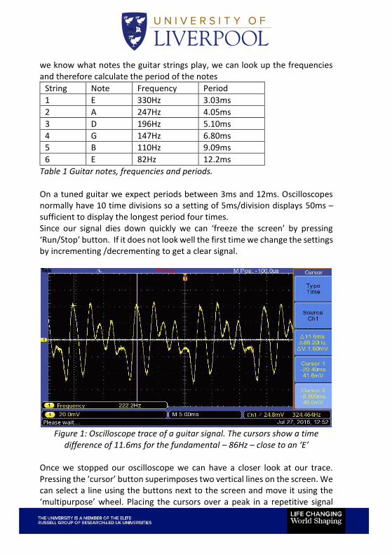
Table 1 Guitar notes, frequencies and periods. On a tuned guitar we expect periods between 3ms and 12ms. Oscilloscopes normally have 10 time divisions so a setting of 5ms/division displays 50ms – sufficient to display the longest period four times. Since our signal dies down quickly we can ‘freeze the screen’ by pressing ‘Run/Stop’ button. If it does not look well the first time we change the settings by incrementing /decrementing to get a clear signal.
Figure 1: Oscilloscope trace of a guitar signal. The cursors show a time
difference of 11.6ms for the fundamental – 86Hz – close to an ‘E’
Once we stopped our oscilloscope we can have a closer look at our trace. Pressing the ‘cursor’ button superimposes two vertical lines on the screen. We can select a line using the buttons next to the screen and move it using the ‘multipurpose’ wheel. Placing the cursors over a peak in a repetitive signal
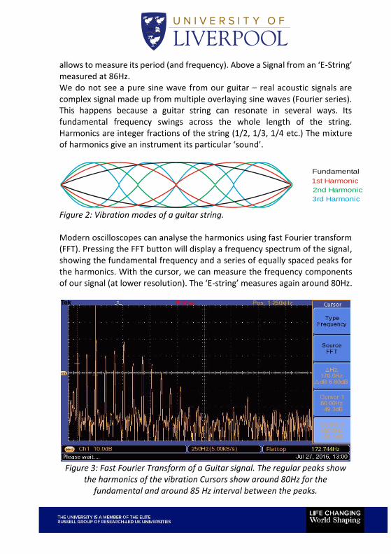
allows to measure its period (and frequency). Above a Signal from an ‘E-String’ measured at 86Hz. We do not see a pure sine wave from our guitar – real acoustic signals are complex signal made up from multiple overlaying sine waves (Fourier series). This happens because a guitar string can resonate in several ways. Its fundamental frequency swings across the whole length of the string. Harmonics are integer fractions of the string (1/2, 1/3, 1/4 etc.) The mixture of harmonics give an instrument its particular ‘sound’.
Fundamental
1st Harmonic
2nd Harmonic
3rd Harmonic
Figure 2: Vibration modes of a guitar string. Modern oscilloscopes can analyse the harmonics using fast Fourier transform (FFT). Pressing the FFT button will display a frequency spectrum of the signal, showing the fundamental frequency and a series of equally spaced peaks for the harmonics. With the cursor, we can measure the frequency components of our signal (at lower resolution). The ‘E-string’ measures again around 80Hz.
Figure 3: Fast Fourier Transform of a Guitar signal. The regular peaks show
the harmonics of the vibration Cursors show around 80Hz for the fundamental and around 85 Hz interval between the peaks.
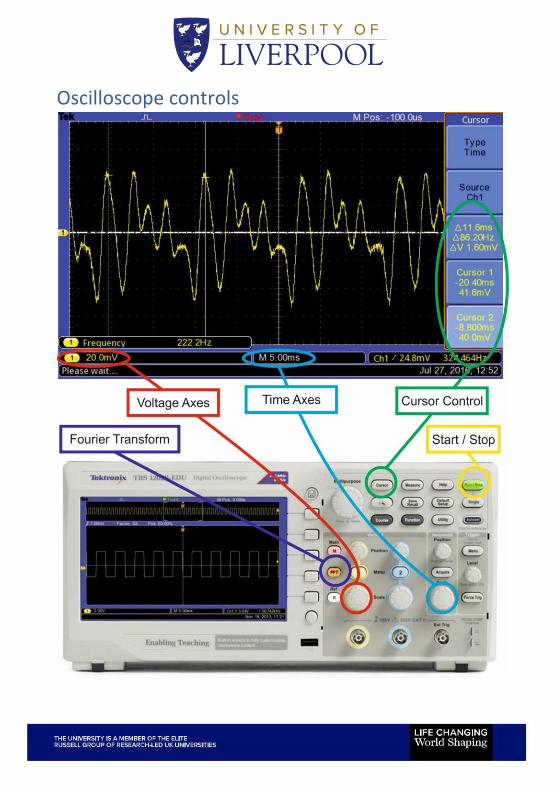
Oscilloscope controls
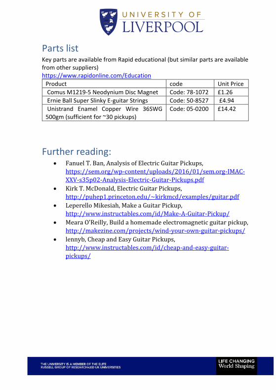
Parts list Key parts are available from Rapid educational (but similar parts are available from other suppliers) https://www.rapidonline.com/Education
Product code Unit Price
Comus M1219-5 Neodynium Disc Magnet Code: 78-1072 £1.26
Ernie Ball Super Slinky E-guitar Strings Code: 50-8527 £4.94
Unistrand Enamel Copper Wire 36SWG 500gm (sufficient for ~30 pickups)
Code: 05-0200 £14.42
Further reading: • Fanuel T. Ban, Analysis of Electric Guitar Pickups,
https://sem.org/wp-content/uploads/2016/01/sem.org-IMAC-
XXV-s35p02-Analysis-Electric-Guitar-Pickups.pdf
• Kirk T. McDonald, Electric Guitar Pickups,
http://puhep1.princeton.edu/~kirkmcd/examples/guitar.pdf
• Leperello Mikesiah, Make a Guitar Pickup,
http://www.instructables.com/id/Make-A-Guitar-Pickup/
• Meara O'Reilly, Build a homemade electromagnetic guitar pickup,
http://makezine.com/projects/wind-your-own-guitar-pickups/
• lennyb, Cheap and Easy Guitar Pickups,
http://www.instructables.com/id/cheap-and-easy-guitar-
pickups/

About the Department of Electrical and
Electronic Engineering.
The Department of Electrical & Electronic Engineering undertakes world class research and offers a highly respected range of undergraduate and postgraduate degree programmes.
We are closely involved with over 50 prominent companies and research organisations worldwide, many of which not only fund and collaborate with us but also make a vital contribution to developing our students.
Our undergraduate and postgraduate programmes achieve consistent top ten rankings in the national surveys. Expert teaching, specialist programmes, work experience and student support are just some of our standout features.
Taught by world-renowned experts, our specialist electrical engineering degrees cover all the key fields of electrical & electronic engineering. Our degree programmes are:
• Electrical & Electronic Engineering
• Avionic Systems (with or without Pilot Studies)
• Computer Science & Electronics
• Mechatronics and Robotic Systems
We continuously update our programmes with new content and modules to reflect the latest research, emerging technologies and industry trends, so what you learn will be the latest thinking.
To maximise student employability we involve leading employers in the development of our courses. Many support us with placements, research project opportunities, guest lecturers, tours and careers events.
You can now take an optional year in industry or study abroad on any of our undergraduate programmes or improve your prospects still further by studying our 4-year MEng programme. This provides eligibility for Chartered Engineer status.
For more information please enquire at [email protected]


![One-Piece BASIC BROOMSTICK CROCHET Broomstick · PDF fileOne-Piece Broomstick Vest Design by Zelda K SKILL LEVEL FINISHED SIZE Women’s small [medium, large] Pattern is written for](https://img.pdfslide.us/doc/110x75/5aae6f8d7f8b9a190d8c2799/one-piece-basic-broomstick-crochet-broomstick-broomstick-vest-design-by-zelda.jpg)