Embed Size (px)
Citation preview

Report No. 103229R-RFCEP76V01
Page: 1 of 51
Test Report
Product Name Notebook Model No. MS-16F1, MS-16F2, MS-16F3, MS-16F4, MS-16F5,
MS-16F6, MS-16F7, MS-16F8, MS-16F9, MS-16FA, MS-16FB, MS-16FC, MS-16FD, MS-16FE, MS-16FF, MS-16FG, MS-16FH, MS-16FI, MS-16FJ, MS-16FK, MS-16FL, MS-16FM, MS-16FN, MS-16FO, MS-16FP, MS-16FQ, MS-16FR, MS-16FS, MS-16FT, MS-16FU, MS-16FV, MS-16FW, MS-16FX, MS-16FY, MS-16FZ, GTzzzz (z=0~9,a~j,A~J or blank)
Transmitter Module Intel / 112BNHMW Bluetooth Module CSR / BSMAN1(MS-3801)
Applicant MICRO-STAR INT'L Co., LTD. Address No. 69, Li-De St., Jung-He City, Taipei Hsien, Taiwan, R.O.C.
Date of Receipt Mar. 12, 2010
Issued Date May. 04, 2010
Report No. 103229R-RFCEP76V01
Report Version V1.0
The Test Results relate only to the samples tested. The test report shall not be reproduced except in full without the written approval of QuieTek Corporation.
Report No. 103229R-RFCEP76V01
Page: 2 of 51
Test Report Cert i f icat ion Issued Date: May. 04, 2010 Report No.: 103229R-RFCEP76V01
Product Name Notebook
Applicant MICRO-STAR INT'L Co., LTD.
Address No. 69, Li-De St., Jung-He City, Taipei Hsien, Taiwan, R.O.C.
Manufacturer MICRO-STAR INT'L Co., LTD.
Model No. MS-16F1, MS-16F2, MS-16F3, MS-16F4, MS-16F5, MS-16F6, MS-16F7,
MS-16F8, MS-16F9, MS-16FA, MS-16FB, MS-16FC, MS-16FD, MS-16FE,
MS-16FF, MS-16FG, MS-16FH, MS-16FI, MS-16FJ, MS-16FK, MS-16FL,
MS-16FM, MS-16FN, MS-16FO, MS-16FP, MS-16FQ, MS-16FR,
MS-16FS, MS-16FT, MS-16FU, MS-16FV, MS-16FW, MS-16FX,
MS-16FY, MS-16FZ, GTzzzz (z=0~9,a~j,A~J or blank)
EUT Rated Voltage AC 100-240V, 50-60Hz
EUT Test Voltage AC 230V/50Hz
Trade Name msi
Applicable Standard ETSI EN 301-489-17:V1.3.2 (2008-04)
ETSI EN 301-489-1: V1.8.1 (2008-04)
Test Result Complied
The test results relate only to the samples tested.
The test report shall not be reproduced except in full without the written approval of QuieTek Corporation.
Documented By :
( Adm. Specialist / Jinn Chen )
Tested By :
( Engineer / Molin Huang )
Approved By :
( Manager / Vincent Lin)
Accredited by DNV, Nemko and NIST (NVLAP)

Report No. 103229R-RFCEP76V01
Page: 3 of 51
TABLE OF CONTENTS Description Page 1. GENERAL INFORMATION..........................................................................................................5 1.1. EUT Description.............................................................................................................................5 1.2. Tested System Details.....................................................................................................................7 1.3. Configuration of tested System ......................................................................................................8 1.4. EUT Exercise Software ..................................................................................................................8 1.5. Test Facility ....................................................................................................................................9 2. Conducted Emission......................................................................................................................10 2.1. Test Equipmen ..............................................................................................................................10 2.2. Test Setup .....................................................................................................................................10 2.3. Limits............................................................................................................................................11 2.4. Test Procedure ..............................................................................................................................12 2.5. Test Specification .........................................................................................................................12 2.6. Uncertainty ...................................................................................................................................12 2.7. Test Result ....................................................................................................................................12 3. Radiated Emission.........................................................................................................................13 3.1. Test Equipment .............................................................................................................................13 3.2. Test Setup .....................................................................................................................................14 3.3. Limits............................................................................................................................................15 3.4. Test Procedure ..............................................................................................................................16 3.5. Test Specification .........................................................................................................................16 3.6. Uncertainty ...................................................................................................................................16 3.7. Test Result ....................................................................................................................................16 4. Power Harmonics, Voltage Fluctuation and Flicker......................................................................17 4.1. Test Equipment .............................................................................................................................17 4.2. Test Setup .....................................................................................................................................17 4.3. Limits............................................................................................................................................17 4.4. Test Procedure ..............................................................................................................................18 4.5. Test Specification .........................................................................................................................18 4.6. Uncertainty ...................................................................................................................................18 4.7. Test Result ....................................................................................................................................19 5. Electrostatic Discharge (ESD) ......................................................................................................20 5.1. Test Equipment .............................................................................................................................20 5.2. Test Setup .....................................................................................................................................20 5.3. Test Level .....................................................................................................................................20 5.4. Test Procedure ..............................................................................................................................21 5.5. Test Specification .........................................................................................................................21 5.6. Uncertainty ...................................................................................................................................21 5.7. Test Result ....................................................................................................................................21 6. Radiated Susceptibility (RS) .........................................................................................................22 6.1. Test Equipment .............................................................................................................................22 6.2. Test Setup .....................................................................................................................................22 6.3. Test Level .....................................................................................................................................22 6.4. Test Procedure ..............................................................................................................................23 6.5. Test Specification .........................................................................................................................23 6.6. Uncertainty ...................................................................................................................................23 6.7. Test Result ....................................................................................................................................23 7. Electrical Fast Transient/Burst (EFT/B)........................................................................................24 7.1. Test Equipment .............................................................................................................................24
Report No. 103229R-RFCEP76V01
Page: 4 of 51
7.2. Test Setup .....................................................................................................................................24 7.3. Test Level .....................................................................................................................................25 7.4. Test Procedure ..............................................................................................................................25 7.5. Test Specification .........................................................................................................................25 7.6. Uncertainty ...................................................................................................................................25 7.7. Test Result ....................................................................................................................................25 8. Surge..............................................................................................................................................26 8.1. Test Equipment .............................................................................................................................26 8.2. Test Setup .....................................................................................................................................26 8.3. Test Level .....................................................................................................................................26 8.4. Test Procedure ..............................................................................................................................27 8.5. Test Specification .........................................................................................................................27 8.6. Uncertainty ...................................................................................................................................27 8.7. Test Result ....................................................................................................................................27 9. Conducted Susceptibility (CS) ......................................................................................................28 9.1. Test Equipment .............................................................................................................................28 9.2. Test Setup .....................................................................................................................................28 9.3. Test Level .....................................................................................................................................28 9.4. Test Procedure ..............................................................................................................................29 9.5. Test Specification .........................................................................................................................29 9.6. Uncertainty ...................................................................................................................................29 9.7. Test Result ....................................................................................................................................29 10. Voltage Dips and Interruption .......................................................................................................30 10.1. Test Equipment .............................................................................................................................30 10.2. Test Setup .....................................................................................................................................30 10.3. Test Level .....................................................................................................................................30 10.4. Test Procedure ..............................................................................................................................31 10.5. Test Specification .........................................................................................................................31 10.6. Uncertainty ...................................................................................................................................31 10.7. Test Result ....................................................................................................................................31 11. EMC Reduction Method During Compliance Testing ..................................................................32 12. Test Result .....................................................................................................................................33 12.1. Test Data of Conducted Emission ................................................................................................34 12.2. Test Data of Radiated Emission....................................................................................................39 12.3. Test Data of Power Harmonics, Voltage Flucturation and Flicker ...............................................41 12.4. Test Data of Electrostatic Discharge ............................................................................................44 12.5. Test Data of Radiated Susceptibility ............................................................................................45 12.6. Test Data of Electrical Fast Transient...........................................................................................46 12.7. Test Data of Surge ........................................................................................................................47 12.8. Test Data of Conducted Susceptibility .........................................................................................48 12.9. Test Data of Voltage Dips and Interruption ..................................................................................49
Attachment 1: EUT Test Photographs
Attachment 2: EUT Detailed Photographs

Report No. 103229R-RFCEP76V01
Page: 5 of 51
1. GENERAL INFORMATION
1.1. EUT Description
Product Name Notebook
Trade Name msi
Model No. MS-16F1, MS-16F2, MS-16F3, MS-16F4, MS-16F5, MS-16F6, MS-16F7,
MS-16F8, MS-16F9, MS-16FA, MS-16FB, MS-16FC, MS-16FD, MS-16FE,
MS-16FF, MS-16FG, MS-16FH, MS-16FI, MS-16FJ, MS-16FK, MS-16FL,
MS-16FM, MS-16FN, MS-16FO, MS-16FP, MS-16FQ, MS-16FR, MS-16FS,
MS-16FT, MS-16FU, MS-16FV, MS-16FW, MS-16FX, MS-16FY, MS-16FZ,
GTzzzz (z=0~9,a~j,A~J or blank)
Frequency Range WLAN: 802.11b/g/n-20: 2412-2472MHz, 802.11n-40: 2422-2452MHz
Bluetooth: 2402-2480MHz
Number of Channels WLAN: 802.11b/g/n-20: 13CH, 802.11n-40: 7CH
Bluetooth: 79CH
Data Rate 802.11b: 1-11Mbps, 802.11g: 6-54Mbps, 802.11n: 6.5-150Mbps
Bluetooth: 1-3Mbps
Channel Separation WLAN: 5 MHz
Bluetooth: 1MHz
Type of Modulation WLAN: 802.11b: DSSS, DBPSK, DQPSK, CCK
802.11g/n: OFDM, BPSK, QPSK, 16QAM, 64QAM
Bluetooth: FHSS
Channel Control Auto
Antenna Gain Refer to the table “Antenna List”
Antenna Type WLAN: PIFA Antenna ; Bluetooth: Chip Antenna
Power Adapter MFR: DELTA, M/N: ADP-150NB
Input: AC 100-240V, 50-60Hz, 2.0A
Output: DC 19.5V, 7.7A
Cable Out: Non-Shielded, 1.8m,with two ferrite cores bonded.
Power Cord: Non-Shielded, 1.8m
Antenna List
No. Manufacturer Part No. Peak Gain
1 VSO S79-1800X20-V03
S79-1800X10-V03
4.38dBi for 2.4GHz

Report No. 103229R-RFCEP76V01
Page: 6 of 51
802.11b/g/n-20MHz Center Frequency of Each Channel (WLAN):
Channel Frequency Channel Frequency Channel Frequency Channel Frequency
Channel 01: 2412 MHz Channel 02: 2417 MHz Channel 03: 2422 MHz Channel 04: 2427 MHz Channel 05: 2432 MHz Channel 06: 2437 MHz Channel 07: 2442 MHz Channel 08: 2447 MHz Channel 09: 2452 MHz Channel 10: 2457 MHz Channel 11: 2462 MHz Channel 12: 2467 MHz Channel 13: 2472 MHz 802.11n-40MHz Center Frequency of Each Channel (WLAN):
Channel Frequency Channel Frequency Channel Frequency Channel Frequency
Channel 01: 2422 MHz Channel 02: 2427 MHz Channel 03: 2432 MHz Channel 04: 2437 MHz Channel 05: 2442 MHz Channel 06: 2447 MHz Channel 07: 2452 MHz Center Frequency of Each Channel (Bluetooth):
Channel Frequency Channel Frequency Channel Frequency Channel Frequency
Channel 00: 2402 MHz Channel 01: 2403 MHz Channel 02: 2404 MHz Channel 03: 2405 MHz Channel 04: 2406 MHz Channel 05: 2407 MHz Channel 06: 2408 MHz Channel 07: 2409 MHz Channel 08: 2410 MHz Channel 09: 2411 MHz Channel 10: 2412 MHz Channel 11: 2413 MHz Channel 12: 2414 MHz Channel 13: 2415 MHz Channel 14: 2416 MHz Channel 15: 2417 MHz Channel 16: 2418 MHz Channel 17: 2419 MHz Channel 18: 2420 MHz Channel 19: 2421 MHz Channel 20: 2422 MHz Channel 21: 2423 MHz Channel 22: 2424 MHz Channel 23: 2425 MHz Channel 24: 2426 MHz Channel 25: 2427 MHz Channel 26: 2428 MHz Channel 27: 2429 MHz Channel 28: 2430 MHz Channel 29: 2431 MHz Channel 30: 2432 MHz Channel 31: 2433 MHz Channel 32: 2434 MHz Channel 33: 2435 MHz Channel 34: 2436 MHz Channel 35: 2437 MHz Channel 36: 2438 MHz Channel 37: 2439 MHz Channel 38: 2440 MHz Channel 39: 2441 MHz Channel 40: 2442 MHz Channel 41: 2443 MHz Channel 42: 2444 MHz Channel 43: 2445 MHz Channel 44: 2446 MHz Channel 45: 2447 MHz Channel 46: 2448 MHz Channel 47: 2449 MHz Channel 48: 2450 MHz Channel 49: 2451 MHz Channel 50: 2452 MHz Channel 51: 2453 MHz Channel 52: 2454 MHz Channel 53: 2455 MHz Channel 54: 2456 MHz Channel 55: 2457 MHz Channel 56: 2458 MHz Channel 57: 2459 MHz Channel 58: 2460 MHz Channel 59: 2461 MHz Channel 60: 2462 MHz Channel 61: 2463 MHz Channel 62: 2464 MHz Channel 63: 2465 MHz Channel 64: 2466 MHz Channel 65: 2467 MHz Channel 66: 2468 MHz Channel 67: 2469 MHz Channel 68: 2470 MHz Channel 69: 2471 MHz Channel 70: 2472 MHz Channel 71: 2473 MHz Channel 72: 2474 MHz Channel 73: 2475 MHz Channel 74: 2476 MHz Channel 75: 2477 MHz Channel 76: 2478 MHz Channel 77: 2479 MHz Channel 78: 2480 MHz Note: 1. The EUT Contains functions and so on WiFi、Bluetooth. 2. The EUT is including thirty-six models for different marketing requirement. 3. QuieTek verified the construction and function in typical operation. All the test modes were carried out with the EUT in normal operation, which was shown in this test report and defined as:
EMI Mode Mode 1: Normal Operation (WiFi+Bluetooth) EMS Mode Mode 1: Normal Operation (WiFi+Bluetooth)

Report No. 103229R-RFCEP76V01
Page: 7 of 51
1.2. Tested System Details
The types for all equipment, plus descriptions of all cables used in the tested system (including inserted cards) are:
Product Manufacturer Model No. Serial No. Power Cord
1 Monitor Dell 2407WFPb CN-0FC255-46633-67T-047S Non-Shielded, 1.8m
2 Walkman AIWA HS-TA164 N/A N/A
3 Microphone &
Earphone
PCHOME N/A N/A N/A
4 USB 3.0 BUFFALO HD-H1.0TU3 15476991123639 Non-Shielded, 1.8m
5 USB 3.0 BUFFALO HD-H1.0TU3 15476991123615 Non-Shielded, 1.8m
6 IPod nano Apple A1236 YM823SWSY0P N/A
7 IPod nano Apple A1236 7K823DNJY0P N/A
8 SATA HDD Onnto ST-M10 A01926-F03-0012 Non-Shielded, 1.8m
9 Notebook PC DELL PP04X 2D2ZM1S Non-Shielded, 1.8m
Signal Cable Type Signal cable Description A D-SUB Cable Shielded, 1.8m, with two ferrite cores bonded B HDMI Cable Shielded, 1.0m C Audio Cable Non-Shielded, 1.6m D Microphone & Earphone Cable Shielded, 1.6m E USB Cable Shielded, 1.5m F USB Cable Shielded, 1.5m G USB Cable Shielded, 1.5m H USB Cable Shielded, 1.5m I e-SATA Cable Shielded, 1.0m J LAN Cable Non-Shielded, 3.0m

Report No. 103229R-RFCEP76V01
Page: 8 of 51
1.3. Configuration of tested System
1.4. EUT Exercise Software
(1) Setup the EUT and peripherals as shown in section 1.3.
(2) Turn on the power of all equipments.
(3) Boot the EUT.
(4) The EUT reads test software from the hard disk.
(5) The EUT and the notebook will show the transmitting and receiving characteristics when the
communication is success.
(6) The wireless LAN & Bluetooth function is used to perform the wireless data transmission.
(7) Repeat the step 5 and 6.

Report No. 103229R-RFCEP76V01
Page: 9 of 51
1.5. Test Facility
Ambient conditions in the laboratory:
Items Test Item Required (IEC 68-1) Actual
Temperature (C) 15-35 20-35
Humidity (%RH) 30-60 50-55
Barometric pressure (mbar)
IEC 61000-4-2
860-1060 950-1000
Temperature (C) 15-35 20-35
Humidity (%RH) 10-75 50-65
Barometric pressure (mbar)
IEC 61000-4-5
860-1060 950-1000
Temperature (C) 15-35 20-35
Barometric pressure (mbar)
IEC 61000-4-4
IEC 61000-4-11 860-1060 950-1000
The related certificate for our laboratories about the test site and management system can be downloaded from
QuieTek Corporation’s Web Site : http://tw.quietek.com/tw/emc/accreditations/accreditations.htm The address and introduction of QuieTek Corporation’s laboratories can be founded in our Web site : http://www.quietek.com/ Site Description: Accredited by NVLAP NVLAP Lab Code: 200533-0 Accredited by DNV Statement No. : 413-99-LAB11
Accredited by Nemko Certificate No.: ELA 165 Accredited by TUV Rheinland Certificate No.: 10011438-1-2009 Accredited by TAF Accredited Number: 0914 Site Name: Quietek Corporation Site Address: No. 5-22, Ruei-Shu Valley, Ruei-Ping Tsuen, Lin-Kou Shiang, Taipei, Taiwan, R.O.C. TEL : 886-2-8601-3788 / FAX : 886-2-8601-3789 E-Mail : [email protected]

Report No. 103229R-RFCEP76V01
Page: 10 of 51
2. Conducted Emission
2.1. Test Equipmen
The following test equipment are used during the conducted emission test:
Item Equipment Manufacturer Model No. / Serial No. Last Cal. Remark
1 Test Receiver R & S ESCS 30 / 825442/018 Sep., 2009
2 Artificial Mains Network R & S ENV4200 / 848411/10 Feb., 2010 Peripherals
3 LISN R & S ESH3-Z5 / 825562/002 Feb., 2010 EUT
4 Pulse Limiter R & S ESH3-Z2 / 357.8810.52 Feb., 2010
5 4-wire ISN R & S ENY41 / 837032/001 Feb., 2010
6 Double 2-Wire ISN R & S ENY22 / 835354/008 Feb., 2010
7 No.1 Shielded Room
Note: All equipments are calibrated every one year.
2.2. Test Setup
Peripheral
80cm
AMN for EUT
Shielded Room
40cm
( EUT )
≧0.8m
AMN for Peripheral
50 ohm Terminator Test Receiver

Report No. 103229R-RFCEP76V01
Page: 11 of 51
2.3. Limits
(1) Mains terminal
Limits (dBuV)
Limit for conducted emissions of
equipment intended to be used in
telecommunication centers only
Limit for conducted emissions Frequency
MHz
QP AV QP AV
0.15 - 0.50 79 66 66-56 56-46
0.50-5.0 73 60 56 46
5.0 - 30 73 60 60 50
Remarks: The limit decreases linearly with the logarithm of the frequency in the range 0.15
MHz ~ 0.50 MHz.
(2) Telecommunication ports
Limits (dBuV)
Limit for conducted emissions from telecommunication ports of
equipment intended for use in telecommunication centers only
Limit for conducted emissions from telecommunication ports
Frequency
MHz
QP AV QP AV
0.15 – 0.50 97-87 84-74 84-74 74-64
5.0 – 30 87 74 74 64
Remarks: In the above table, the tighter limit applies at the band edges.

Report No. 103229R-RFCEP76V01
Page: 12 of 51
2.4. Test Procedure
AC Mains:
The EUT and simulators are connected to the main power through a line impedance stabilization
network (L.I.S.N.). This provides a 50 ohm /50uH coupling impedance for the measuring equipment.
The peripheral devices are also connected to the main power through a LISN that provides a 50ohm
/50uH coupling impedance with 50ohm termination. (Please refers to the block diagram of the test
setup and photographs.)
Both sides of AC line are checked for maximum conducted interference. In order to find the
maximum emission, the relative positions of equipment and all of the interface cables must be changed
according to ETSI EN 301489-1: V1.8.1 (2008-04) on conducted measurement.
The bandwidth of the field strength meter (R & S Test Receiver ESCS 30) is set at 9kHz.
Telecommunication Port:
The mains voltage shall be supplied to the EUT via the LISN when the measurement of
telecommunication port is performed. The common mode disturbances at the telecommunication port
shall be connected to the ISN, which is 150ohm impedance. Both alternative cables are tested related
to the LCL requested. The measurement range is from 150kHz to 30MHz. The bandwidth of
measurement is set to 9kHz. The 60dB LCL ISN is used for cat. 5 cable, 50dB LCL ISN is used for cat.
3 and 80dB LCL is wed for alternative one.
2.5. Test Specification
According to ETSI EN 301489-1: V1.8.1 (2008-04)
EN 55022: 2006+A1: 2007
2.6. Uncertainty
± 2.26 dB
2.7. Test Result
The emission from the EUT was below the specified limits. The worst-case emissions are shown in
section 12. The EUT complies the acceptance criterion and passes the test.
Report No. 103229R-RFCEP76V01
Page: 13 of 51
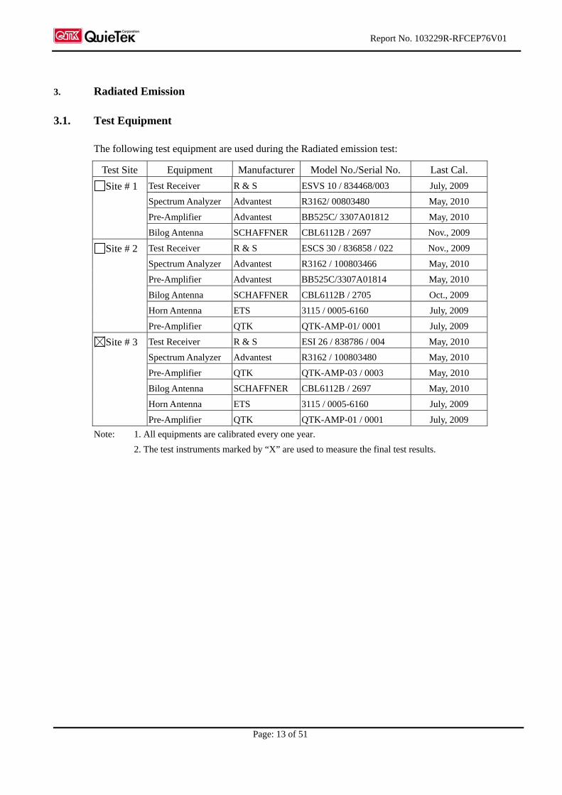
3. Radiated Emission
3.1. Test Equipment
The following test equipment are used during the Radiated emission test:
Test Site Equipment Manufacturer Model No./Serial No. Last Cal.
Test Receiver R & S ESVS 10 / 834468/003 July, 2009
Spectrum Analyzer Advantest R3162/ 00803480 May, 2010
Pre-Amplifier Advantest BB525C/ 3307A01812 May, 2010
Site # 1
Bilog Antenna SCHAFFNER CBL6112B / 2697 Nov., 2009
Test Receiver R & S ESCS 30 / 836858 / 022 Nov., 2009
Spectrum Analyzer Advantest R3162 / 100803466 May, 2010
Pre-Amplifier Advantest BB525C/3307A01814 May, 2010
Bilog Antenna SCHAFFNER CBL6112B / 2705 Oct., 2009
Horn Antenna ETS 3115 / 0005-6160 July, 2009
Site # 2
Pre-Amplifier QTK QTK-AMP-01/ 0001 July, 2009
Test Receiver R & S ESI 26 / 838786 / 004 May, 2010
Spectrum Analyzer Advantest R3162 / 100803480 May, 2010
Pre-Amplifier QTK QTK-AMP-03 / 0003 May, 2010
Bilog Antenna SCHAFFNER CBL6112B / 2697 May, 2010
Horn Antenna ETS 3115 / 0005-6160 July, 2009
Site # 3
Pre-Amplifier QTK QTK-AMP-01 / 0001 July, 2009
Note: 1. All equipments are calibrated every one year.
2. The test instruments marked by “X” are used to measure the final test results.

Report No. 103229R-RFCEP76V01
Page: 14 of 51
3.2. Test Setup
Radiated Emission Below 1GHz
Radiated Emission Above 1GHz
EUT
FRP Dome
The height of broad band
or Dipole Antenna was
scanned from 1M to 4M.
The distance between
antenna and turn table
was 3M regards to the
standard adopted.
3m
80cm
To Receiver Pre- Amplifier
EUT
FRP Dome
Test Receiver
The height of broad
band antenna was
scanned from 1m to 4m.
The distance between
antenna and turn table
was 10m..
To Controller
To ReceiverFully soldered Metal Ground
Non-Conducted Table
10m
1m to 4m
80cm

Report No. 103229R-RFCEP76V01
Page: 15 of 51
3.3. Limits
Limits for radiated disturbance under 1 GHz at a measurement distance of 10 m
Limits (dBuV/m)
Limit for radiated emissions from
ancillary equipment intended for
use in telecommunication centers
only, and measured on a stand
alone basis
Limit for radiated emissions from
ancillary equipment, measured on
a stand alone basis
Frequency
MHz
QP QP
30-230 40 30
230-1000 47 37
Limits for radiated disturbance above 1 GHz at a measurement distance of 3 m
Frequency range Average Limit (dBµV/m) Peak limit (dBµV/m)
1 000 MHz to 3 000 MHz 50 70
3 000 MHz to 6 000 MHz 54 74
NOTE: The lower limit applies at the transition frequency.
Limits above 1 GHz for radiated emissions from ancillary equipment intended for use in
telecommunication centres only,and measured on a stand alone basis at a measurement
distance of 3 m
Frequency range Average Limit (dBµV/m) Peak limit (dBµV/m)
1 000 MHz to 3 000 MHz 56 76
3 000 MHz to 6 000 MHz 60 80
NOTE: The lower limit applies at the transition frequency.
Report No. 103229R-RFCEP76V01
Page: 16 of 51
3.4. Test Procedure
The EUT and its simulators are placed on a turn table which is 0.8 meter above ground. The turn table can
rotate 360 degrees to determine the position of the maximum emission level. The EUT was positioned
such that the distance from antenna to the EUT was 10 meters.
The antenna can move up and down between 1 meter and 4 meters to find out the maximum emission
level.
Both horizontal and vertical polarization of the antenna are set on measurement. In order to find the
maximum emission, all of the interface cables must be manipulated on radiated measurement.
Radiated emissions were invested over the frequency range from 30MHz to1GHz using a receiver
bandwidth of 120kHz. Radiated was performed at an antenna to EUT distance of 10 meters.
Radiated emissions were invested over the frequency range from 1GHz to 6GHz using a receiver
bandwidth of 1MHz. Radiated was performed at an antenna to EUT distance of 3 meters.
3.5. Test Specification
According to ETSI EN 301489-1: V1.8.1 (2008-04)
EN 55022: 2006+A1: 2007
3.6. Uncertainty
± 3.8 dB
3.7. Test Result
The emission from the EUT was below the specified limits. The worst-case emissions are shown in
section 12. The EUT complies the acceptance criterion and passes the test.

Report No. 103229R-RFCEP76V01
Page: 17 of 51
4. Power Harmonics, Voltage Fluctuation and Flicker
4.1. Test Equipment
Item Instrument 4Manufacturer Type No/Serial No. Last Calibration
1 Power Harmonics
Tester
SCHAFFNER Profline 2105-400
S/N: HK54148
June, 2009
2 Analyzer SCHAFFNER CCN 1000-1/X71887 June, 2009
3 No.3 Shielded Room
Note: All equipments are calibrated every one year.
4.2. Test Setup
4.3. Limits
Limits of Class A Harmonics Currents
Harmonics Order
n
Maximum Permissible harmonic current
A
Harmonics Order
n
Maximum Permissible harmonic current
A
Odd harmonics Even harmonics
3 2.30 2 1.08
5 1.14 4 0.43
7 0.77 6 0.30
9 0.40 8 n 40 0.23 * 8/n
11 0.33
13 0.21
15 n 39 0.15 * 15/n
Limits of Class B Harmonics Currents
For Class B equipment, the harmonic of the input current shall not exceed the maximum permissible
values given in table that is the limit of Class A multiplied by a factor of 1.5.
Power Analyzer Impedance Network
Power Source
EUT Load
Controller PC
Non-Conducted
Report No. 103229R-RFCEP76V01
Page: 18 of 51
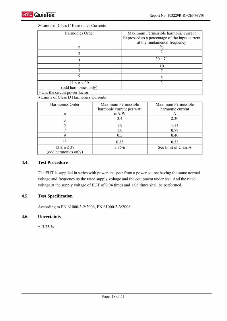
Limits of Class C Harmonics Currents
Harmonics Order
n
Maximum Permissible harmonic current Expressed as a percentage of the input current
at the fundamental frequency %
2 2
3 30.λ*
5 10 7 7 9 5
11 n 39 (odd harmonics only)
3
*λ is the circuit power factor Limits of Class D Harmonics Currents
Harmonics Order
n
Maximum Permissible harmonic current per watt
mA/W
Maximum Permissible harmonic current
A
3 3.4 2.30
5 1.9 1.14 7 1.0 0.77 9 0.5 0.40 11 0.35 0.33
13 n 39 (odd harmonics only)
3.85/n See limit of Class A
4.4. Test Procedure
The EUT is supplied in series with power analyzer from a power source having the same normal
voltage and frequency as the rated supply voltage and the equipment under test. And the rated
voltage at the supply voltage of EUT of 0.94 times and 1.06 times shall be performed.
4.5. Test Specification
According to EN 61000-3-2:2006, EN 61000-3-3:2008
4.6. Uncertainty
± 3.23 %
Report No. 103229R-RFCEP76V01
Page: 19 of 51
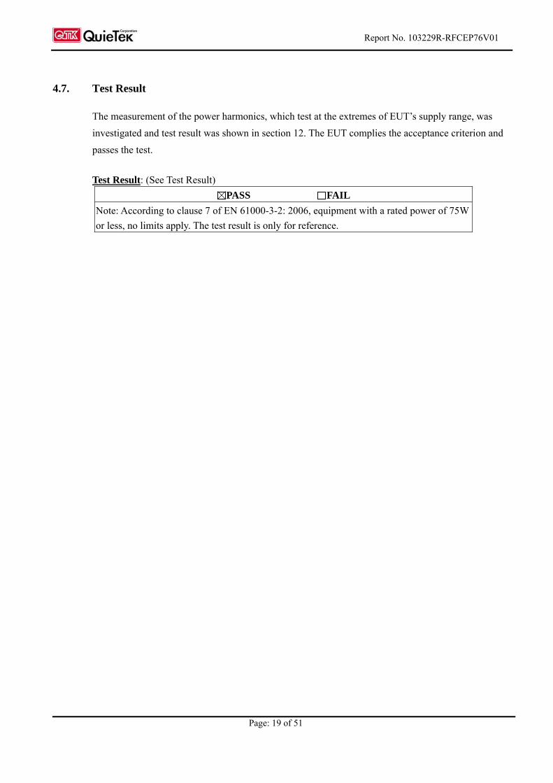
4.7. Test Result
The measurement of the power harmonics, which test at the extremes of EUT’s supply range, was
investigated and test result was shown in section 12. The EUT complies the acceptance criterion and
passes the test.
Test Result: (See Test Result)
PASS FAIL
Note: According to clause 7 of EN 61000-3-2: 2006, equipment with a rated power of 75W
or less, no limits apply. The test result is only for reference.

Report No. 103229R-RFCEP76V01
Page: 20 of 51
5. Electrostatic Discharge (ESD)
5.1. Test Equipment
Item Instrument Manufacturer Type No/Serial No. Last Calibration
1 ESD Simulator System SCHAFFNER NSG-438 S/N: 167 June, 2009
2 Horizontal Coupling Plane (HCP)
QuieTek HCP AL50 N/A
3 Vertical Coupling Plane (VCP)
QuieTek VCP AL50 N/A
4 No.3 Shielded Room
Note: All equipments are calibrated every one year.
5.2. Test Setup
5.3. Test Level
Item Environmental Phenomena Units Test Specification Performance Criteria
Enclosure Port
Electrostatic Discharge kV(Charge Voltage) ±8 Air Discharge
±4 Contact Discharge B
Metal Ground Plane
ESD Simulator
EUT Loads: Active Insulation
Horizontal Coupling Plane
Non-Conducted table 470K ohm Resistor
470K ohm Resistor
Vertical Coupling Plane
80cm
Report No. 103229R-RFCEP76V01
Page: 21 of 51
5.4. Test Procedure
Direct application of discharges to the EUT:
Contact discharge was applied only to conductive surfaces of the EUT.
Air discharges were applied only to non-conductive surfaces of the EUT.
During the test, it was performed with single discharges. For the single discharge time
between successive single discharges will be keep longer 1 second. It was at least ten single
discharges with positive and negative at the same selected point.
The selected point, which was performed with electrostatic discharge, was marked on the
red label of the EUT.
Indirect application of discharges to the EUT:
Vertical Coupling Plane (VCP):
The coupling plane, of dimensions 0.5m x 0.5m, is placed parallel to, and positioned at a
distance 0.1m from, the EUT, with the Discharge Electrode touching the coupling plane.
The four faces of the EUT will be performed with electrostatic discharge. It was at least ten
single discharges with positive and negative at the same selected point.
Horizontal Coupling Plane (HCP):
The coupling plane is placed under to the EUT. The generator shall be positioned vertically
at a distance of 0.1m from the EUT, with the Discharge Electrode touching the coupling
plane.
The four faces of the EUT will be performed with electrostatic discharge. It was at least ten
single discharges with positive and negative at the same selected point.
5.5. Test Specification
According to IEC 61000-4-2 :2008
5.6. Uncertainty
± 6.003 %
5.7. Test Result
The measurement of the electrostatic discharge was investigated and test result was shown in section
12. The EUT complies the acceptance criterion and passes the test.
Report No. 103229R-RFCEP76V01
Page: 22 of 51
6. Radiated Susceptibility (RS)
6.1. Test Equipment
Item Equipment Manufacturer Model No. / Serial No. Last Cal.
1 Signal Generator R & S SMY02 / 825454/029 Oct., 2009
2 Power Amplifier A & R 100W10000M7 / A285000010
N/A
3 RF Power Amplifier OPHIRRF 5022F / 1075 N/A
4 Bilog Antenna Chase CBL6112B / 2452 Sep., 2009
5 Power Meter R & S NRVD / 100219 Jan., 2010
6 Directional Coupler A & R DC6180 / 22735 Jan., 2010
7 No.2 EMC Fully Chamber
Note: All equipments are calibrated every one year.
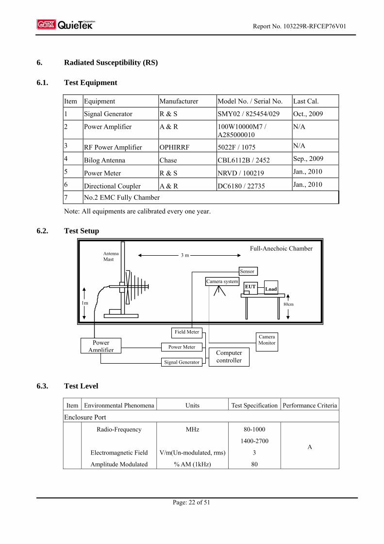
6.2. Test Setup
6.3. Test Level
Item Environmental Phenomena Units Test Specification Performance Criteria
Enclosure Port
Radio-Frequency
Electromagnetic Field
Amplitude Modulated
MHz
V/m(Un-modulated, rms)
% AM (1kHz)
80-1000
1400-2700
3
80
A
EUT
Sensor
80cm
3 m
1m
Full-Anechoic Chamber
Power Amplifier
Signal Generator
Field Meter
Computer controller
Camera system
Camera Monitor
AntennaMast
Load
Power Meter
Report No. 103229R-RFCEP76V01
Page: 23 of 51
6.4. Test Procedure
The EUT and load, which are placed on a table that is 0.8 meter above ground, are placed with
one coincident with the calibration plane such that the distance from antenna to the EUT was 3
meters.
Both horizontal and vertical polarization of the antenna and four sides of the EUT are set on
measurement.
In order to judge the EUT performance, a CCD camera is used to monitor EUT screen.
All the scanning conditions are as follows:
Condition of Test Remarks
1. Field Strength 3 V/m Level 2
2. Radiated Signal AM 80% Modulated with 1kHz sinusoidal audio signal
3. Scanning Frequency 80MHz - 1000MHz, 1400MHz - 2700MHz
4 Dwell Time 3 Seconds
5. Frequency step size f : 1%
6. The rate of Swept of Frequency 1.5 x 10⁻³ decades/s
6.5. Test Specification
According to IEC 61000-4-3 :2008
6.6. Uncertainty
± 6.17 %
6.7. Test Result
The measurement of the radiated susceptibility was investigated and test result was shown in section
12. The EUT complies the acceptance criterion and passes the test.

Report No. 103229R-RFCEP76V01
Page: 24 of 51
7. Electrical Fast Transient/Burst (EFT/B)
7.1. Test Equipment
Item Instrument Manufacturer Type No/Serial No. Last Calibration
1 Fast Transient/Burst
Generator
SCHAFFNER NSG 2050
S/N: 200124-031AR
June, 2009
2 No.3 Shielded Room
Note: All equipments are calibrated every one year.
7.2. Test Setup
Report No. 103229R-RFCEP76V01
Page: 25 of 51
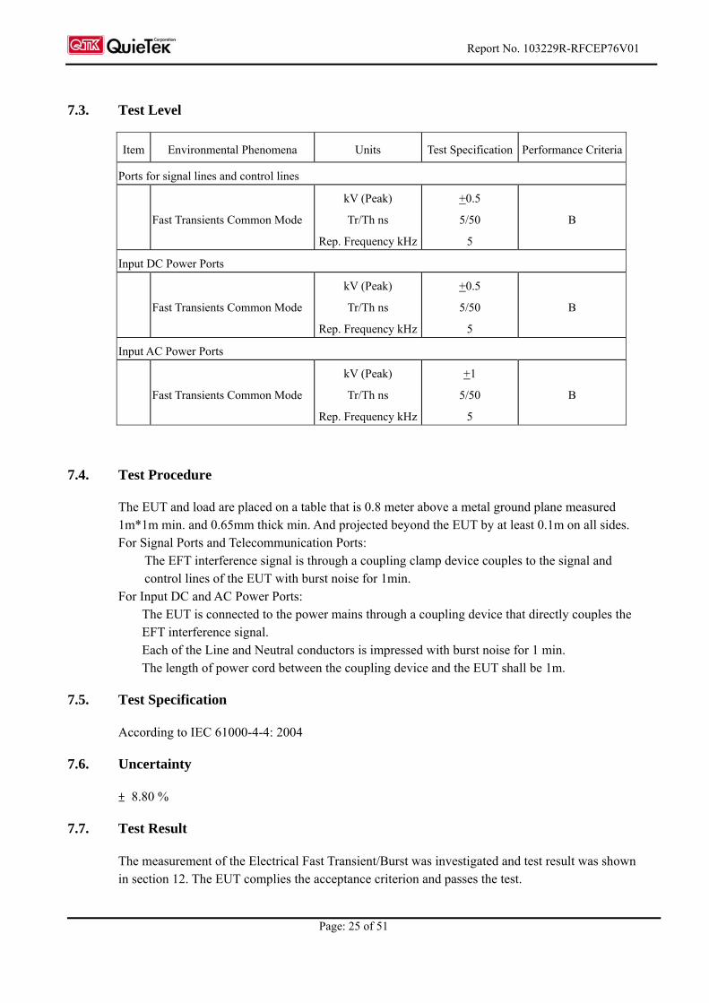
7.3. Test Level
Item Environmental Phenomena Units Test Specification Performance Criteria
Ports for signal lines and control lines
Fast Transients Common Mode
kV (Peak)
Tr/Th ns
Rep. Frequency kHz
+0.5
5/50
5
B
Input DC Power Ports
Fast Transients Common Mode
kV (Peak)
Tr/Th ns
Rep. Frequency kHz
+0.5
5/50
5
B
Input AC Power Ports
Fast Transients Common Mode
kV (Peak)
Tr/Th ns
Rep. Frequency kHz
+1
5/50
5
B
7.4. Test Procedure
The EUT and load are placed on a table that is 0.8 meter above a metal ground plane measured 1m*1m min. and 0.65mm thick min. And projected beyond the EUT by at least 0.1m on all sides. For Signal Ports and Telecommunication Ports:
The EFT interference signal is through a coupling clamp device couples to the signal and control lines of the EUT with burst noise for 1min.
For Input DC and AC Power Ports: The EUT is connected to the power mains through a coupling device that directly couples the EFT interference signal. Each of the Line and Neutral conductors is impressed with burst noise for 1 min. The length of power cord between the coupling device and the EUT shall be 1m.
7.5. Test Specification
According to IEC 61000-4-4: 2004
7.6. Uncertainty
± 8.80 %
7.7. Test Result
The measurement of the Electrical Fast Transient/Burst was investigated and test result was shown in section 12. The EUT complies the acceptance criterion and passes the test.
Report No. 103229R-RFCEP76V01
Page: 26 of 51
8. Surge
8.1. Test Equipment
Item Instrument Manufacturer Type No/Serial No. Last Calibration
1 Surge Generator SCHAFFNER NSG 2050
S/N: 200124-031AR
June, 2009
2 No.3 Shielded Room
Note: All equipments are calibrated every one year.
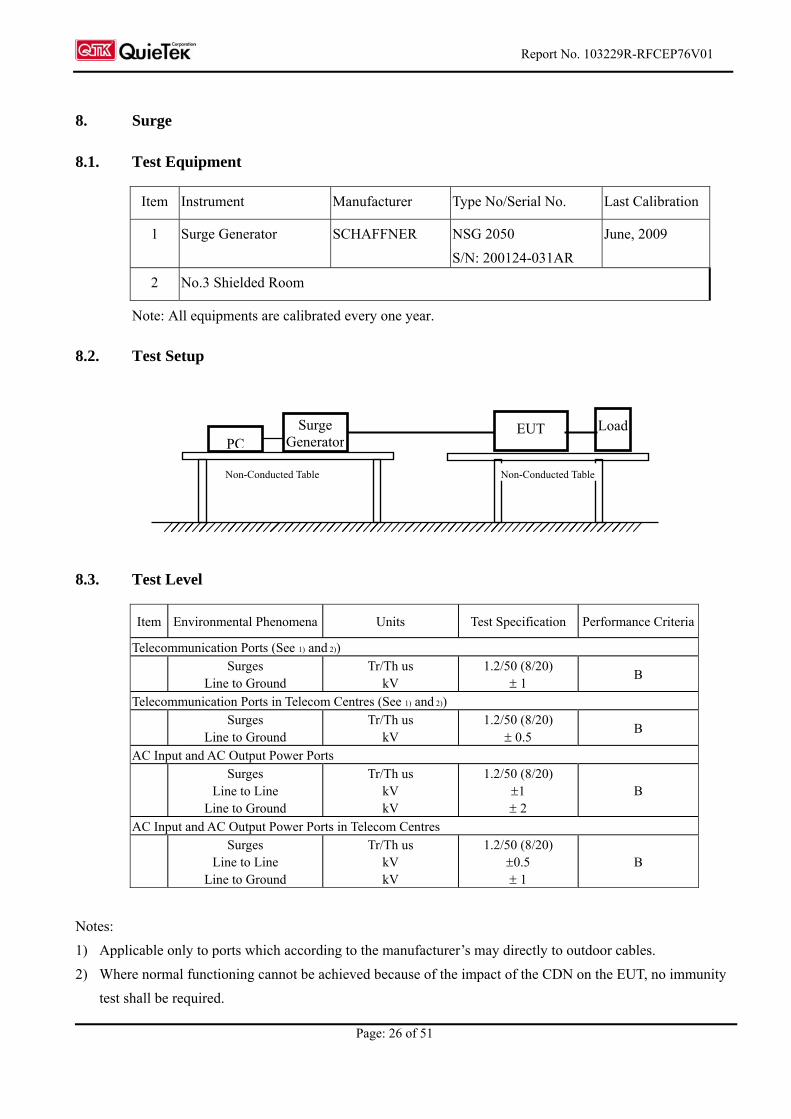
8.2. Test Setup
8.3. Test Level
Item Environmental Phenomena Units Test Specification Performance Criteria
Telecommunication Ports (See 1) and 2))
Surges
Line to Ground Tr/Th us
kV 1.2/50 (8/20)
1 B
Telecommunication Ports in Telecom Centres (See 1) and 2))
Surges
Line to Ground Tr/Th us
kV 1.2/50 (8/20)
0.5 B
AC Input and AC Output Power Ports
Surges
Line to Line Line to Ground
Tr/Th us kV kV
1.2/50 (8/20) 1 2
B
AC Input and AC Output Power Ports in Telecom Centres
Surges
Line to Line Line to Ground
Tr/Th us kV kV
1.2/50 (8/20) 0.5 1
B
Notes:
1) Applicable only to ports which according to the manufacturer’s may directly to outdoor cables.
2) Where normal functioning cannot be achieved because of the impact of the CDN on the EUT, no immunity
test shall be required.
Surge Generator
EUT Load PC
Non-Conducted Table Non-Conducted Table
Report No. 103229R-RFCEP76V01
Page: 27 of 51
8.4. Test Procedure
The EUT and its load are placed on a table that is 0.8 meter above a metal ground plane measured
1m*1m min. and 0.65mm thick min. And projected beyond the EUT by at least 0.1m on all sides. The
length of power cord between the coupling device and the EUT shall be 2m or less.
For Signal Ports and Telecommunication Ports
The disturbance signal is through a coupling and decoupling networks (CDN) device couples to
the signal and Telecommunication lines of the EUT.
For Input and Output AC Power or DC Input and DC Output Power Ports:
The EUT is connected to the power mains through a coupling device that directly couples the
Surge interference signal.
The surge noise shall be applied synchronized to the voltage phase at 00, 900, 1800, 2700 and the
peak value of the a.c. voltage wave. (Positive and negative)
Each of Line-Earth and Line-Line is impressed with a sequence of five surge voltages with
interval of 1 min.
8.5. Test Specification
According to IEC 61000-4-5: 2005
8.6. Uncertainty
± 7.93 %
8.7. Test Result
The measurement of the Surge was investigated and test result was shown in section 12. The EUT
complies the acceptance criterion and passes the test.
Report No. 103229R-RFCEP76V01
Page: 28 of 51
9. Conducted Susceptibility (CS)
9.1. Test Equipment
Item Equipment Manufacturer Model No. / Serial No. Last Cal.
1 CS SYSTEM SCHAFFNER NSG 2070 March, 2010
2 CDN SCHAFFNER CDN M016S / 20822 Dec., 2009
3 CDN SCHAFFNER CDN M016S / 20823 Dec., 2009
4 FIXED PAD SCHAFFNER INA 2070-1 / 2115 N/A
5 EM Clamp KEMZ 801 / 21024 March, 2010
6 No.6 Shielded Room
Note: All equipments are calibrated every one year.
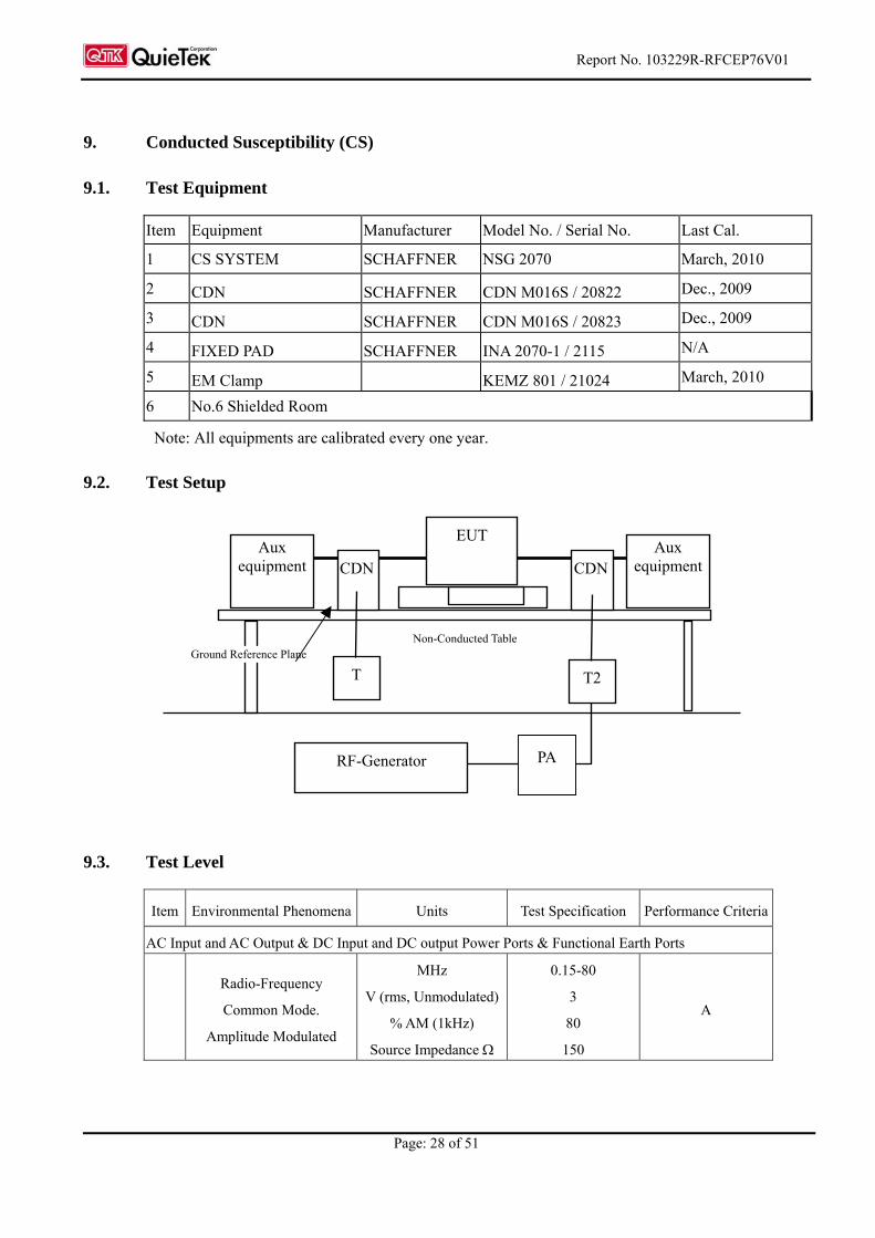
9.2. Test Setup
9.3. Test Level
Item Environmental Phenomena Units Test Specification Performance Criteria
AC Input and AC Output & DC Input and DC output Power Ports & Functional Earth Ports
Radio-Frequency
Common Mode.
Amplitude Modulated
MHz
V (rms, Unmodulated)
% AM (1kHz)
Source Impedance
0.15-80
3
80
150
A
Aux equipment
EUT
CDN
RF-Generator
T2
Ground Reference Plane Non-Conducted Table
CDNAux
equipment
T
PA

Report No. 103229R-RFCEP76V01
Page: 29 of 51
9.4. Test Procedure
The EUT are placed on a table that is 0.8 meter height, and a Ground reference plane on the table,
EUT are placed upon table and use a 10cm insulation between the EUT and Ground reference
plane.
For Signal Ports and Telecommunication Ports
The disturbance signal is through a coupling and decoupling networks (CDN) or EM-clamp
device couples to the signal and Telecommunication lines of the EUT.
For Input DC and AC Power Ports
The EUT is connected to the power mains through a coupling and decoupling networks for power
supply lines. And directly couples the disturbances signal into EUT.
Used CDN-M2 for two wires or CDN-M3 for three wires.
All the scanning conditions are as follows:
Condition of Test Remarks
1. Field Strength 130dBuV(3V) Level 2
2. Radiated Signal AM 80% Modulated with 1kHz sinusoidal audio signal
3. Scanning Frequency 0.15MHz – 80MHz
4 Dwell Time 3 Seconds
5. Frequency step size f : 1%
6. The rate of Swept of Frequency 1.5 x 10⁻³ decades/s
9.5. Test Specification
According to IEC 61000-4-6 :2008
9.6. Uncertainty
± 6.17 %
9.7. Test Result
The measurement of the Conducted Susceptibility was investigated and test result was shown in
section 12. The EUT complies the acceptance criterion and passes the test.

Report No. 103229R-RFCEP76V01
Page: 30 of 51
10. Voltage Dips and Interruption
10.1. Test Equipment
Item Instrument Manufacturer Type No/Serial No. Last Calibration
1 Voltage Dips Generator SCHAFFNER NSG 2050
S/N: 200124-031AR
June, 2009
2 No.3 Shielded Room
Note: All equipments are calibrated every one year.
10.2. Test Setup
10.3. Test Level
Item Environmental Phenomena Units Test Specification Performance Criteria
AC Input and AC Output Power Ports
Voltage Dips % Reduction
(Cycle)
100 %
0.5 B
Voltage Dips % Reduction
(Cycle)
100 %
1 B
Voltage Dips % Reduction
(Cycle)
30 %
25 B
Voltage Interruptions % Reduction
(Cycle)
100 %
250 C (see note)
NOTE: Equipment is fitted with or connected to a battery back-up, the performance criteria is “B”.
Voltage Dips/ Interruptions /Variations Simulator
EUT Load To AC Line
Controller Computer Printer
Non-Conducted Table 80cm
AC Power Line to EUT

Report No. 103229R-RFCEP76V01
Page: 31 of 51
10.4. Test Procedure
The EUT and its load are placed on a table which is 0.8 meter above a metal ground plane
measured 1m*1m min. and 0.65mm thick min. And projected beyond the EUT by at least 0.1m
on all sides. The power cord shall be used the shortest power cord as specified by the
manufacturer.
For Voltage Dips/ Interruptions test:
The selection of test voltage is based on the rated power range. If the operation range is large
than 20% of lower power range, both end of specified voltage shall be tested. Otherwise, the
typical voltage specification is selected as test voltage.
The EUT is connected to the power mains through a coupling device that directly couples to
the Voltage Dips and Interruption Generator.
The test levels shall be:
voltage dip: 0 % residual voltage for 0,5 cycle;
voltage dip: 0 % residual voltage for 1 cycle;
voltage dip: 70 % residual voltage for 25 cycles (at 50 Hz);
voltage interruption: 0 % residual voltage for 250 cycles (at 50 Hz).
Voltage phase shifting are shall occur at 00, 450, 900 ,1350 ,1800 ,2250, 2700 ,3150 of the voltage.
10.5. Test Specification
According to IEC 61000-4-11 :2004
10.6. Uncertainty
± 2.03 %
10.7. Test Result
The measurement of the Voltage Dips and Interruption was investigated and test result was shown in
section 12. The EUT complies the acceptance criterion and passes the test.

Report No. 103229R-RFCEP76V01
Page: 32 of 51
11. EMC Reduction Method During Compliance Testing
No modification was made during testing.

Report No. 103229R-RFCEP76V01
Page: 33 of 51
12. Test Result
The test results in the emission and the immunity were performed according to the requirements of
measurement standard and process. Quietek Corporation is assumed full responsibility for the
accuracy and completeness of these measurements. The test data of the emission is listed as below.
All the tests were carried out with the EUT in normal operation, which was defined as:
EMI Mode Mode 1: Normal Operation (WiFi+Bluetooth) EMS Mode Mode 1: Normal Operation (WiFi+Bluetooth)
Report No. 103229R-RFCEP76V01
Page: 34 of 51
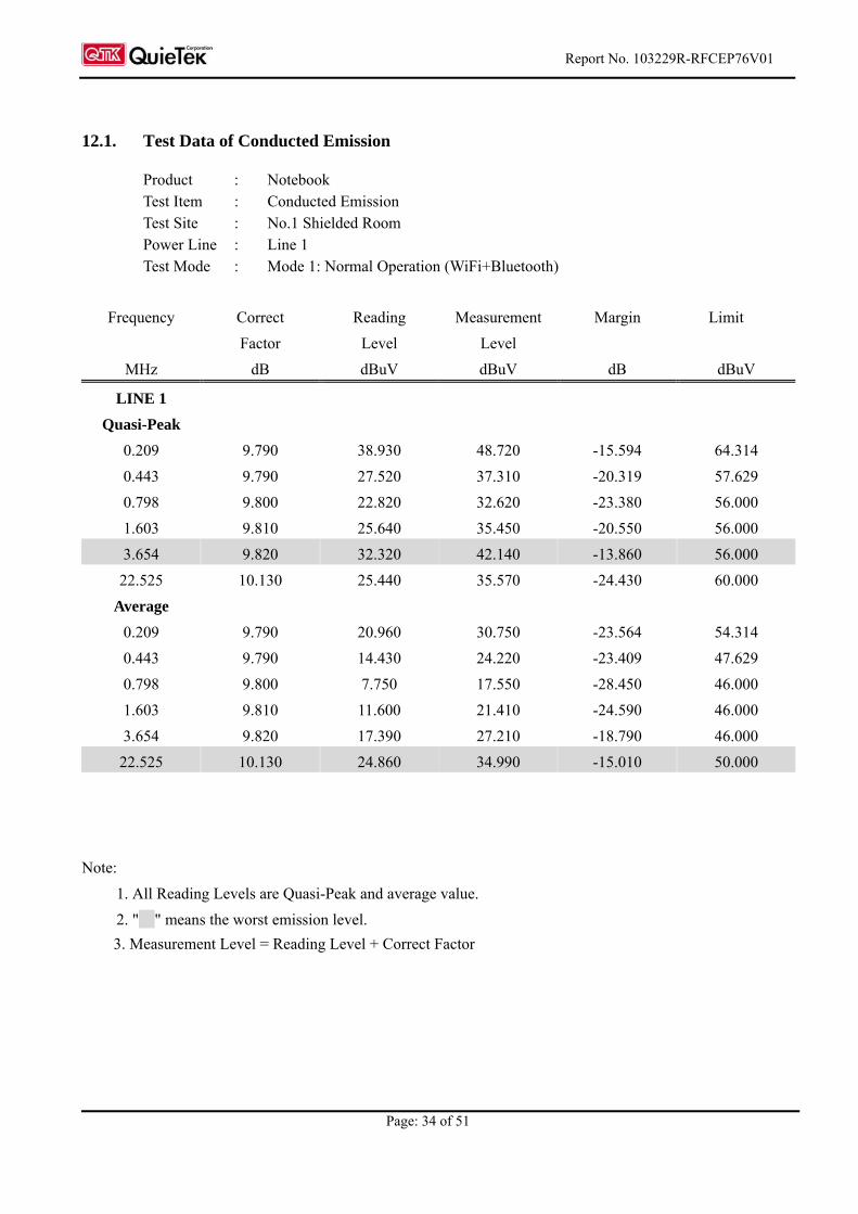
12.1. Test Data of Conducted Emission
Product : Notebook Test Item : Conducted Emission Test Site : No.1 Shielded Room Power Line : Line 1 Test Mode : Mode 1: Normal Operation (WiFi+Bluetooth)
Frequency Correct Reading Measurement Margin Limit
Factor Level Level
MHz dB dBuV dBuV dB dBuV
LINE 1
Quasi-Peak
0.209 9.790 38.930 48.720 -15.594 64.314
0.443 9.790 27.520 37.310 -20.319 57.629
0.798 9.800 22.820 32.620 -23.380 56.000
1.603 9.810 25.640 35.450 -20.550 56.000
3.654 9.820 32.320 42.140 -13.860 56.000
22.525 10.130 25.440 35.570 -24.430 60.000
Average
0.209 9.790 20.960 30.750 -23.564 54.314
0.443 9.790 14.430 24.220 -23.409 47.629
0.798 9.800 7.750 17.550 -28.450 46.000
1.603 9.810 11.600 21.410 -24.590 46.000
3.654 9.820 17.390 27.210 -18.790 46.000
22.525 10.130 24.860 34.990 -15.010 50.000
Note:
1. All Reading Levels are Quasi-Peak and average value.
2. " " means the worst emission level.
3. Measurement Level = Reading Level + Correct Factor
Report No. 103229R-RFCEP76V01
Page: 35 of 51
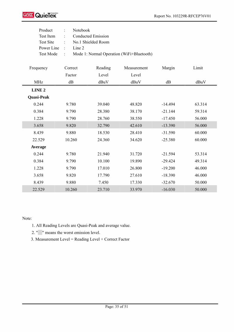
Product : Notebook Test Item : Conducted Emission Test Site : No.1 Shielded Room Power Line : Line 2 Test Mode : Mode 1: Normal Operation (WiFi+Bluetooth)
Frequency Correct Reading Measurement Margin Limit
Factor Level Level
MHz dB dBuV dBuV dB dBuV
LINE 2
Quasi-Peak
0.244 9.780 39.040 48.820 -14.494 63.314
0.384 9.790 28.380 38.170 -21.144 59.314
1.228 9.790 28.760 38.550 -17.450 56.000
3.658 9.820 32.790 42.610 -13.390 56.000
8.439 9.880 18.530 28.410 -31.590 60.000
22.529 10.260 24.360 34.620 -25.380 60.000
Average
0.244 9.780 21.940 31.720 -21.594 53.314
0.384 9.790 10.100 19.890 -29.424 49.314
1.228 9.790 17.010 26.800 -19.200 46.000
3.658 9.820 17.790 27.610 -18.390 46.000
8.439 9.880 7.450 17.330 -32.670 50.000
22.529 10.260 23.710 33.970 -16.030 50.000
Note:
1. All Reading Levels are Quasi-Peak and average value.
2. " " means the worst emission level.
3. Measurement Level = Reading Level + Correct Factor

Report No. 103229R-RFCEP76V01
Page: 36 of 51
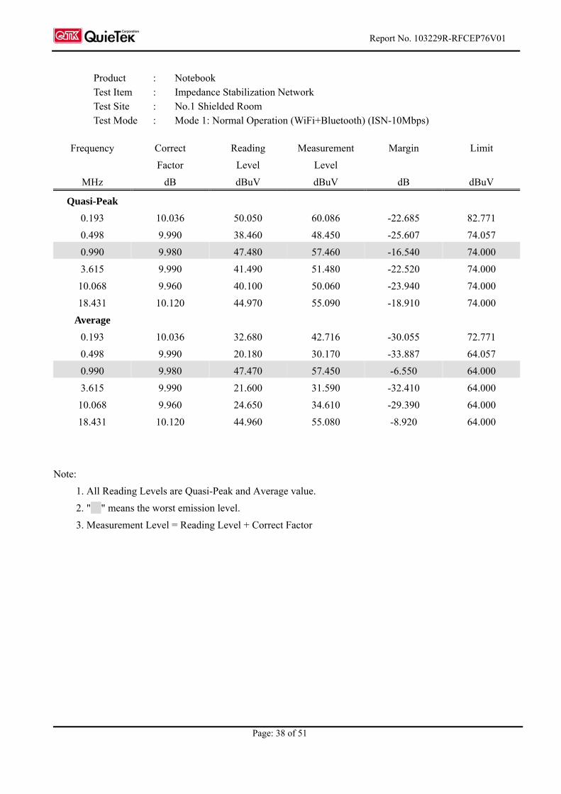
Product : Notebook Test Item : Impedance Stabilization Network Test Site : No.1 Shielded Room Test Mode : Mode 1: Normal Operation (WiFi+Bluetooth) (ISN-1Gbps)
Frequency Correct Reading Measurement Margin Limit
Factor Level Level
MHz dB dBuV dBuV dB dBuV
Quasi-Peak
0.220 10.226 49.310 59.536 -22.464 82.000
0.716 10.140 37.200 47.340 -26.660 74.000
0.990 10.110 47.970 58.080 -15.920 74.000
1.982 10.070 43.200 53.270 -20.730 74.000
3.642 10.060 45.200 55.260 -18.740 74.000
18.431 10.260 45.300 55.560 -18.440 74.000
Average
0.220 10.226 36.400 46.626 -25.374 72.000
0.716 10.140 28.770 38.910 -25.090 64.000
0.990 10.110 47.960 58.070 -5.930 64.000
1.982 10.070 42.310 52.380 -11.620 64.000
3.642 10.060 28.600 38.660 -25.340 64.000
18.431 10.260 44.660 54.920 -9.080 64.000
Note:
1. All Reading Levels are Quasi-Peak and Average value.
2. " " means the worst emission level.
3. Measurement Level = Reading Level + Correct Factor

Report No. 103229R-RFCEP76V01
Page: 37 of 51
Product : Notebook Test Item : Impedance Stabilization Network Test Site : No.1 Shielded Room Test Mode : Mode 1: Normal Operation (WiFi+Bluetooth) (ISN-100Mbps)
Frequency Correct Reading Measurement Margin Limit
Factor Level Level
MHz dB dBuV dBuV dB dBuV
Quasi-Peak
0.170 10.043 50.040 60.083 -23.346 83.429
0.365 10.008 43.500 53.508 -24.349 77.857
0.990 9.980 47.660 57.640 -16.360 74.000
3.615 9.990 41.750 51.740 -22.260 74.000
10.060 9.960 45.000 54.960 -19.040 74.000
23.127 10.100 50.310 60.410 -13.590 74.000
Average
0.170 10.043 31.980 42.023 -31.406 73.429
0.365 10.008 34.790 44.798 -23.059 67.857
0.990 9.980 47.580 57.560 -6.440 64.000
3.615 9.990 28.230 38.220 -25.780 64.000
10.060 9.960 40.680 50.640 -13.360 64.000
23.127 10.100 48.530 58.630 -5.370 64.000
Note:
1. All Reading Levels are Quasi-Peak and Average value.
2. " " means the worst emission level.
3. Measurement Level = Reading Level + Correct Factor
Report No. 103229R-RFCEP76V01
Page: 38 of 51
Frequency Correct Reading Measurement Margin Limit
Factor Level Level
MHz dB dBuV dBuV dB dBuV
Quasi-Peak
0.193 10.036 50.050 60.086 -22.685 82.771
0.498 9.990 38.460 48.450 -25.607 74.057
0.990 9.980 47.480 57.460 -16.540 74.000
3.615 9.990 41.490 51.480 -22.520 74.000
10.068 9.960 40.100 50.060 -23.940 74.000
18.431 10.120 44.970 55.090 -18.910 74.000
Average
0.193 10.036 32.680 42.716 -30.055 72.771
0.498 9.990 20.180 30.170 -33.887 64.057
0.990 9.980 47.470 57.450 -6.550 64.000
3.615 9.990 21.600 31.590 -32.410 64.000
10.068 9.960 24.650 34.610 -29.390 64.000
18.431 10.120 44.960 55.080 -8.920 64.000
Note:
1. All Reading Levels are Quasi-Peak and Average value.
2. " " means the worst emission level.
3. Measurement Level = Reading Level + Correct Factor
Product : Notebook Test Item : Impedance Stabilization Network Test Site : No.1 Shielded Room Test Mode : Mode 1: Normal Operation (WiFi+Bluetooth) (ISN-10Mbps)
Report No. 103229R-RFCEP76V01
Page: 39 of 51
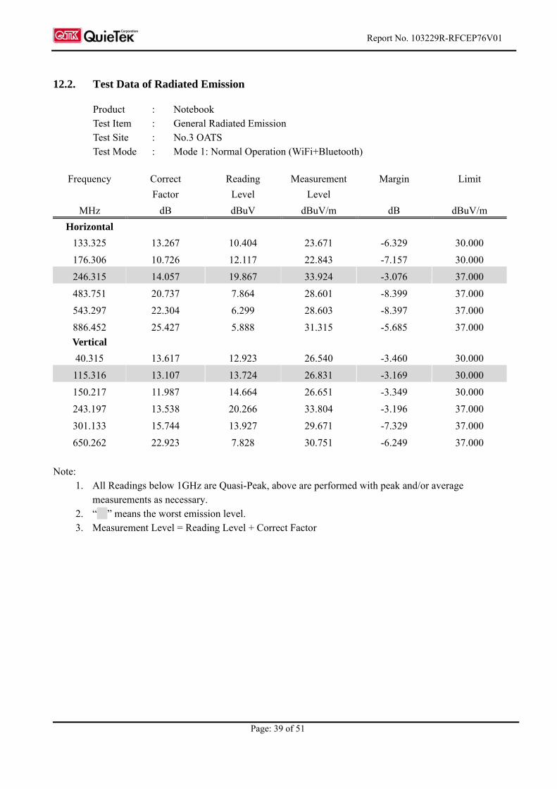
12.2. Test Data of Radiated Emission
Product : Notebook Test Item : General Radiated Emission Test Site : No.3 OATS Test Mode : Mode 1: Normal Operation (WiFi+Bluetooth)
Note:
1. All Readings below 1GHz are Quasi-Peak, above are performed with peak and/or average measurements as necessary.
2. “ ” means the worst emission level. 3. Measurement Level = Reading Level + Correct Factor
Frequency Correct Reading Measurement Margin Limit
Factor Level Level
MHz dB dBuV dBuV/m dB dBuV/m
Horizontal
133.325 13.267 10.404 23.671 -6.329 30.000
176.306 10.726 12.117 22.843 -7.157 30.000
246.315 14.057 19.867 33.924 -3.076 37.000
483.751 20.737 7.864 28.601 -8.399 37.000
543.297 22.304 6.299 28.603 -8.397 37.000
886.452 25.427 5.888 31.315 -5.685 37.000
Vertical
40.315 13.617 12.923 26.540 -3.460 30.000
115.316 13.107 13.724 26.831 -3.169 30.000
150.217 11.987 14.664 26.651 -3.349 30.000
243.197 13.538 20.266 33.804 -3.196 37.000
301.133 15.744 13.927 29.671 -7.329 37.000
650.262 22.923 7.828 30.751 -6.249 37.000
Report No. 103229R-RFCEP76V01
Page: 40 of 51
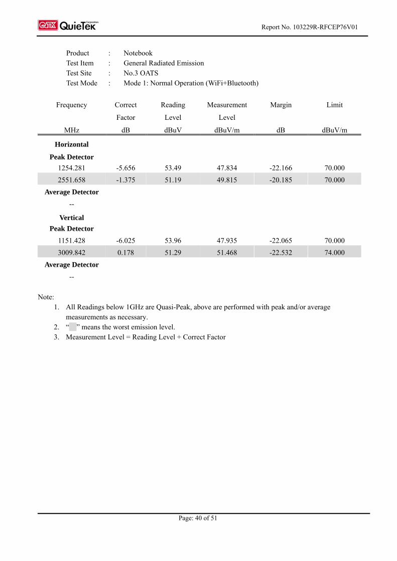
Product : Notebook Test Item : General Radiated Emission Test Site : No.3 OATS Test Mode : Mode 1: Normal Operation (WiFi+Bluetooth)
Frequency Correct Reading Measurement Margin Limit
Factor Level Level
MHz dB dBuV dBuV/m dB dBuV/m
Horizontal
Peak Detector
1254.281 -5.656 53.49 47.834 -22.166 70.000
2551.658 -1.375 51.19 49.815 -20.185 70.000
Average Detector
--
Vertical
Peak Detector
1151.428 -6.025 53.96 47.935 -22.065 70.000
3009.842 0.178 51.29 51.468 -22.532 74.000
Average Detector
--
Note:
1. All Readings below 1GHz are Quasi-Peak, above are performed with peak and/or average measurements as necessary.
2. “ ” means the worst emission level. 3. Measurement Level = Reading Level + Correct Factor

Report No. 103229R-RFCEP76V01
Page: 41 of 51
12.3. Test Data of Power Harmonics, Voltage Flucturation and Flicker
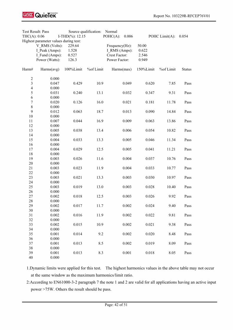
Product : Notebook Test Item : Power Harmonics Classification : Class D Test Mode : Mode 1: Normal Operation (WiFi+Bluetooth)
Test Result: Pass Source qualification: Normal
Current & voltage waveforms
-1.5
-1.0
-0.5
0.0
0.5
1.0
1.5
-300
-200
-100
0
100
200
300
Cu
rre
nt (A
mp
s)
Vo
ltag
e (V
olts)
Harmonics and Class D limit line European Limits
0.0
0.1
0.2
0.3
0.4
0.5
0.6
Cu
rre
nt R
MS
(Am
ps)
Harmonic #4 8 12 16 20 24 28 32 36 40
Test result: Pass Worst harmonic was #9 with 20.09% of the limit.
Report No. 103229R-RFCEP76V01
Page: 42 of 51
Test Result: Pass Source qualification: Normal THC(A): 0.06 I-THD(%): 12.15 POHC(A): 0.006 POHC Limit(A): 0.054 Highest parameter values during test:
V_RMS (Volts): 229.64 Frequency(Hz): 50.00 I_Peak (Amps): 1.528 I_RMS (Amps): 0.622 I_Fund (Amps): 0.527 Crest Factor: 2.546 Power (Watts): 126.3 Power Factor: 0.949
Harm# Harms(avg) 100%Limit %of Limit Harms(max) 150%Limit %of Limit Status 2 0.000 3 0.047 0.429 10.9 0.049 0.620 7.85 Pass 4 0.000 5 0.031 0.240 13.1 0.032 0.347 9.31 Pass 6 0.000 7 0.020 0.126 16.0 0.021 0.181 11.78 Pass 8 0.000 9 0.012 0.063 18.7 0.013 0.090 14.84 Pass 10 0.000 11 0.007 0.044 16.9 0.009 0.063 13.86 Pass 12 0.000 13 0.005 0.038 13.4 0.006 0.054 10.82 Pass 14 0.000 15 0.004 0.033 13.3 0.005 0.046 11.34 Pass 16 0.000 17 0.004 0.029 12.5 0.005 0.041 11.21 Pass 18 0.000 19 0.003 0.026 11.6 0.004 0.037 10.76 Pass 20 0.000 21 0.003 0.023 11.9 0.004 0.033 10.77 Pass 22 0.000 23 0.003 0.021 13.3 0.003 0.030 10.97 Pass 24 0.000 25 0.003 0.019 13.0 0.003 0.028 10.40 Pass 26 0.000 27 0.002 0.018 12.5 0.003 0.026 9.92 Pass 28 0.000 29 0.002 0.017 11.7 0.002 0.024 9.40 Pass 30 0.000 31 0.002 0.016 11.9 0.002 0.022 9.81 Pass 32 0.000 33 0.002 0.015 10.9 0.002 0.021 9.38 Pass 34 0.000 35 0.001 0.014 9.2 0.002 0.020 8.48 Pass 36 0.000 37 0.001 0.013 8.5 0.002 0.019 8.09 Pass 38 0.000 39 0.001 0.013 8.3 0.001 0.018 8.05 Pass 40 0.000
1.Dynamic limits were applied for this test. The highest harmonics values in the above table may not occur
at the same window as the maximum harmonics/limit ratio.
2:According to EN61000-3-2 paragraph 7 the note 1 and 2 are valid for all applications having an active input
power >75W. Others the result should be pass.
Report No. 103229R-RFCEP76V01
Page: 43 of 51
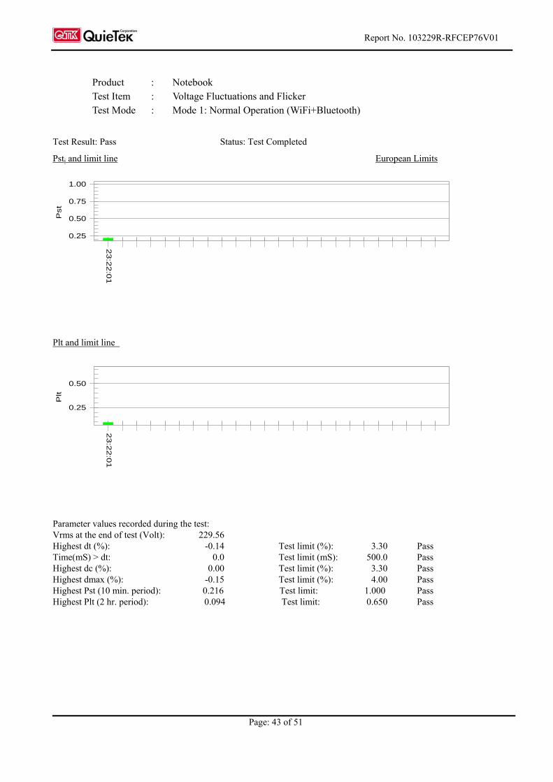
Product : Notebook Test Item : Voltage Fluctuations and Flicker Test Mode : Mode 1: Normal Operation (WiFi+Bluetooth)
Test Result: Pass Status: Test Completed
Psti and limit line European Limits
0.25
0.50
0.75
1.00
Pst
23:2
2:0
1
Plt and limit line
0.25
0.50
Plt
23:2
2:0
1
Parameter values recorded during the test: Vrms at the end of test (Volt): 229.56 Highest dt (%): -0.14 Test limit (%): 3.30 Pass Time(mS) > dt: 0.0 Test limit (mS): 500.0 Pass Highest dc (%): 0.00 Test limit (%): 3.30 Pass Highest dmax (%): -0.15 Test limit (%): 4.00 Pass Highest Pst (10 min. period): 0.216 Test limit: 1.000 Pass Highest Plt (2 hr. period): 0.094 Test limit: 0.650 Pass

Report No. 103229R-RFCEP76V01
Page: 44 of 51
12.4. Test Data of Electrostatic Discharge
Product : Notebook Test Item : Electrostatic Discharge Test Site : No.3 Shielded Room Test Mode : Mode 1: Normal Operation (WiFi+Bluetooth)
Item Amount of
Discharge Voltage
Required
Criteria
Complied To Criteria
(A, B, C) Results
Air Discharge 10
10
+2KV ,+4KV ,+8kV
-2KV ,-4KV ,-8kV
B
B
B
B
Pass
Pass
Contact Discharge 25
25
+2KV ,+4kV
-2KV ,-4kV
B
B
B
B
Pass
Pass
Indirect Discharge
(HCP)
25
25
+2KV ,+4kV
-2KV ,-4kV
B
B
A
A
Pass
Pass
Indirect Discharge
(VCP Front)
25
25
+2KV ,+4kV
-2KV ,-4kV
B
B
A
A
Pass
Pass
Indirect Discharge
(VCP Left)
25
25
+2KV ,+4kV
-2KV ,-4kV
B
B
A
A
Pass
Pass
Indirect Discharge
(VCP Back)
25
25
+2KV ,+4kV
-2KV ,-4kV
B
B
A
A
Pass
Pass
Indirect Discharge
(VCP Right)
25
25
+2KV ,+4kV
-2KV ,-4kV
B
B
A
A
Pass
Pass
Note:
The testing performed is from lowest level up to the highest level as required by standard, but only highest
level is shown on the report.
NR: No Requirement
Meet criteria A: Operate as intended during and after the test Meet criteria B: Operate as intended after the test Meet criteria C: Loss/Error of function Additional Information
EUT stopped operation and could / could not be reset by operator at kV. No false alarms or other malfunctions were observed during or after the test.

Report No. 103229R-RFCEP76V01
Page: 45 of 51
12.5. Test Data of Radiated Susceptibility
Product : Notebook Test Item : Radiated Susceptibility Test Site : No.2 EMC fully Chamber Test Mode : Mode 1: Normal Operation (WiFi+Bluetooth)
Frequency (MHz)
Position (Angle)
Polarity(H or V)
Field Strength (V/m)
Required Criteria
Complied To Criteria
(A, B, C) Results
80-1000 Front H 3 A A Pass 80-1000 Front V 3 A A Pass 80-1000 Back H 3 A A Pass 80-1000 Back V 3 A A Pass 80-1000 Left H 3 A A Pass 80-1000 Left V 3 A A Pass 80-1000 Right H 3 A A Pass 80-1000 Right V 3 A A Pass 80-1000 Top H 3 A A Pass 80-1000 Top V 3 A A Pass 80-1000 Down H 3 A A Pass 80-1000 Down V 3 A A Pass
1400-2700 Front H 3 A A Pass 1400-2700 Front V 3 A A Pass 1400-2700 Back H 3 A A Pass 1400-2700 Back V 3 A A Pass 1400-2700 Left H 3 A A Pass 1400-2700 Left V 3 A A Pass 1400-2700 Right H 3 A A Pass 1400-2700 Right V 3 A A Pass 1400-2700 Top H 3 A A Pass 1400-2700 Top V 3 A A Pass 1400-2700 Down H 3 A A Pass 1400-2700 Down V 3 A A Pass
Note:
The exclusion band for the transmitter and/or receiver part of the 2.45GHz RLAM equipment under test
shall extend from 2280MHz to 2607.675MHz.
Meet criteria A: Operate as intended during and after the test Meet criteria B: Operate as intended after the test Meet criteria C: Loss/Error of function Additional Information
There was no observable degradation in performance. EUT stopped operation and could / could not be reset by operator at V/m
at frequency MHz. No false alarms or other malfunctions were observed during or after the test.

Report No. 103229R-RFCEP76V01
Page: 46 of 51
12.6. Test Data of Electrical Fast Transient
Product : Notebook Test Item : Electrical Fast Transient Test Site : No.3 Shielded Room Test Mode : Mode 1: Normal Operation (WiFi+Bluetooth)
Note:
The testing performed is from lowest level up to the highest level as required by standard, but only highest
level is shown on the report.
Meet criteria A : Operate as intended during and after the test
Meet criteria B : Operate as intended after the test
Meet criteria C : Loss/Error of function
Additional Information
EUT stopped operation and could / could not be reset by operator at kV of
Line .
No false alarms or other malfunctions were observed during or after the test.
Inject
Line Polarity
Voltage
(kV)
Inject
Time
(Second)
Inject
Method
Required
Criteria
Complied to
Criteria Result
L+N+PE ± 1kV 60 Direct B A PASS
LAN ± 0.5 kV 60 Clamp B A PASS

Report No. 103229R-RFCEP76V01
Page: 47 of 51
12.7. Test Data of Surge
Product : Notebook Test Item : Surge Test Site : No. 3 Shielded Room Test Mode : Mode 1: Normal Operation (WiFi+Bluetooth)
Inject
Line Polarity Angle
Voltage
(kV)
Time
Interval
(Second)
Inject
Method
Required
Criteria
Complied to
Criteria Result
L-N ± 0 1 60 Direct B A Pass
L-N ± 90 1 60 Direct B A Pass
L-N ± 180 1 60 Direct B A Pass
L-N ± 270 1 60 Direct B A Pass
N-PE ± 0 2 60 Direct B A Pass
N-PE ± 90 2 60 Direct B A Pass
N-PE ± 180 2 60 Direct B A Pass
N-PE ± 270 2 60 Direct B A Pass
L-PE ± 0 2 60 Direct B A Pass
L-PE ± 90 2 60 Direct B A Pass
L-PE ± 180 2 60 Direct B A Pass
L-PE ± 270 2 60 Direct B A Pass
Note: The testing performed is from lowest level up to the highest level as required by standard, but only highest
level is shown on the report.
Meet criteria A : Operate as intended during and after the test
Meet criteria B : Operate as intended after the test
Meet criteria C : Loss/Error of function
Additional Information
EUT stopped operation and could / could not be reset by operator at kV of
Line .
No false alarms or other malfunctions were observed during or after the test.
Report No. 103229R-RFCEP76V01
Page: 48 of 51
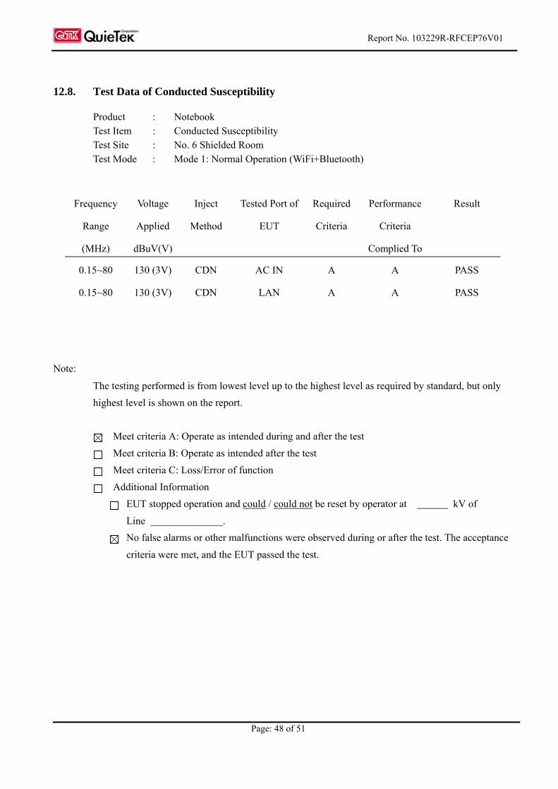
12.8. Test Data of Conducted Susceptibility
Product : Notebook Test Item : Conducted Susceptibility Test Site : No. 6 Shielded Room Test Mode : Mode 1: Normal Operation (WiFi+Bluetooth)
Frequency
Range
(MHz)
Voltage
Applied
dBuV(V)
Inject
Method
Tested Port of
EUT
Required
Criteria
Performance
Criteria
Complied To
Result
0.15~80 130 (3V) CDN AC IN A A PASS
0.15~80 130 (3V) CDN LAN A A PASS
Note:
The testing performed is from lowest level up to the highest level as required by standard, but only
highest level is shown on the report.
Meet criteria A: Operate as intended during and after the test
Meet criteria B: Operate as intended after the test
Meet criteria C: Loss/Error of function
Additional Information
EUT stopped operation and could / could not be reset by operator at kV of
Line .
No false alarms or other malfunctions were observed during or after the test. The acceptance
criteria were met, and the EUT passed the test.
Report No. 103229R-RFCEP76V01
Page: 49 of 51
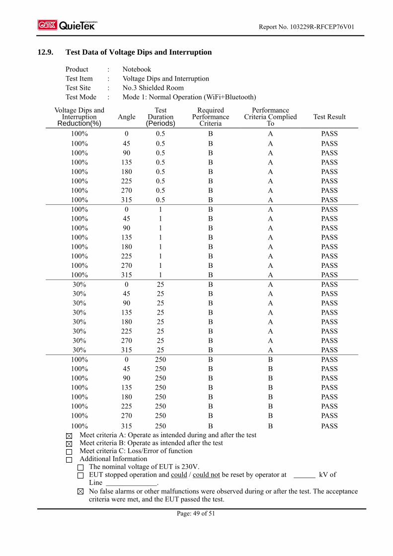
12.9. Test Data of Voltage Dips and Interruption
Product : Notebook Test Item : Voltage Dips and Interruption Test Site : No.3 Shielded Room Test Mode : Mode 1: Normal Operation (WiFi+Bluetooth)
Voltage Dips and
Interruption Reduction(%)
Angle Test
Duration (Periods)
Required Performance
Criteria
Performance Criteria Complied
To Test Result
100% 0 0.5 B A PASS 100% 45 0.5 B A PASS 100% 90 0.5 B A PASS 100% 135 0.5 B A PASS 100% 180 0.5 B A PASS 100% 225 0.5 B A PASS 100% 270 0.5 B A PASS 100% 315 0.5 B A PASS 100% 0 1 B A PASS 100% 45 1 B A PASS 100% 90 1 B A PASS 100% 135 1 B A PASS 100% 180 1 B A PASS 100% 225 1 B A PASS 100% 270 1 B A PASS 100% 315 1 B A PASS 30% 0 25 B A PASS 30% 45 25 B A PASS 30% 90 25 B A PASS 30% 135 25 B A PASS 30% 180 25 B A PASS 30% 225 25 B A PASS 30% 270 25 B A PASS 30% 315 25 B A PASS
100% 0 250 B B PASS 100% 45 250 B B PASS 100% 90 250 B B PASS 100% 135 250 B B PASS 100% 180 250 B B PASS 100% 225 250 B B PASS 100% 270 250 B B PASS
100% 315 250 B B PASS Meet criteria A: Operate as intended during and after the test Meet criteria B: Operate as intended after the test Meet criteria C: Loss/Error of function Additional Information
The nominal voltage of EUT is 230V. EUT stopped operation and could / could not be reset by operator at kV of
Line . No false alarms or other malfunctions were observed during or after the test. The acceptance
criteria were met, and the EUT passed the test.
Report No. 103229R-RFCEP76V01
Page: 50 of 51
Attachment 1: EUT Test Photographs
Report No.: 103229R-RFCEP76V01
Page : 1 of 8
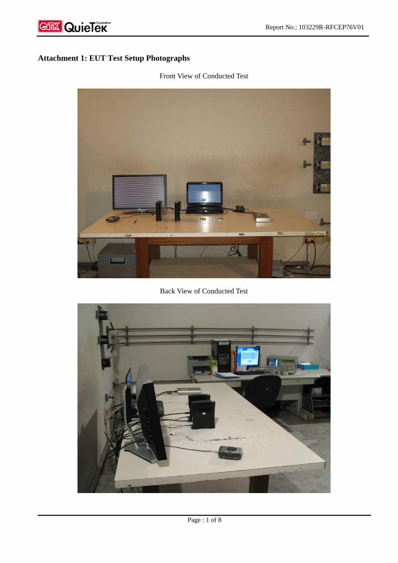
Attachment 1: EUT Test Setup Photographs
Front View of Conducted Test
Back View of Conducted Test

Report No.: 103229R-RFCEP76V01
Page : 2 of 8
Front View of Conducted Test (ISN)
Back View of Conducted Test (ISN)

Report No.: 103229R-RFCEP76V01
Page : 3 of 8
Front View of Radiated Test (Bilog)
Back View of Radiated Test

Report No.: 103229R-RFCEP76V01
Page : 4 of 8
Front View of Radiated Test (Horn)
Power Harmonics Test Setup
Report No.: 103229R-RFCEP76V01
Page : 5 of 8
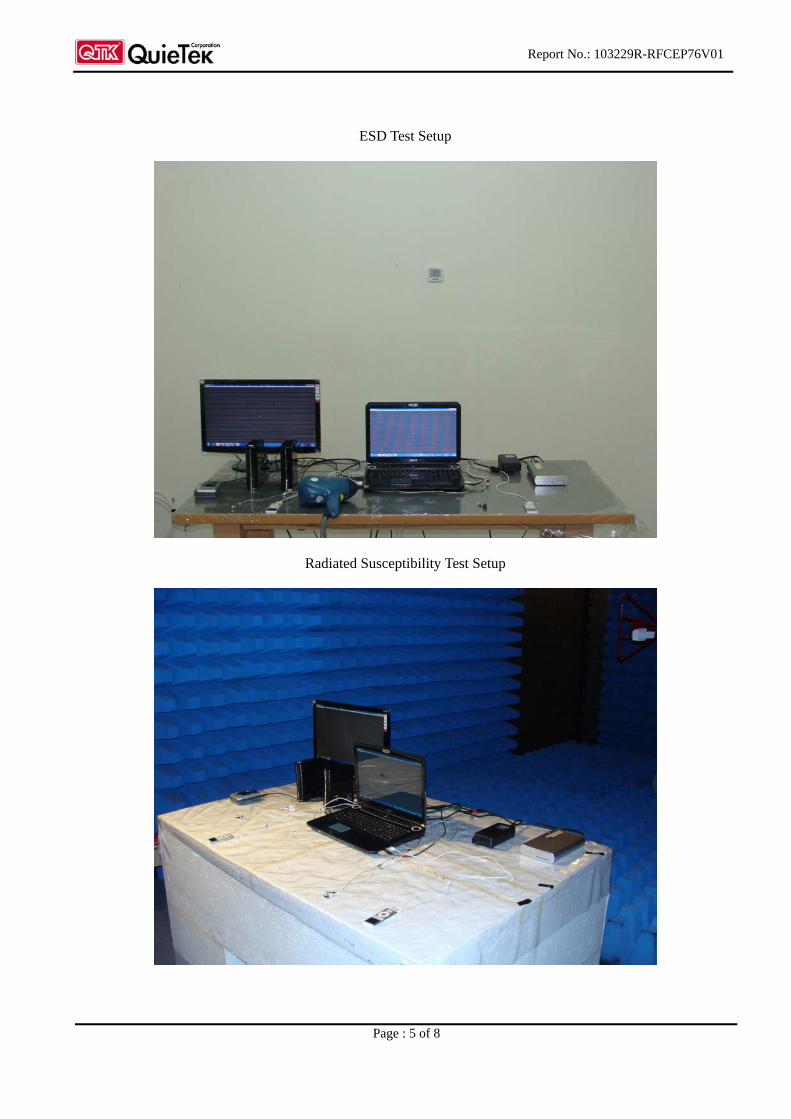
ESD Test Setup
Radiated Susceptibility Test Setup
Report No.: 103229R-RFCEP76V01
Page : 6 of 8
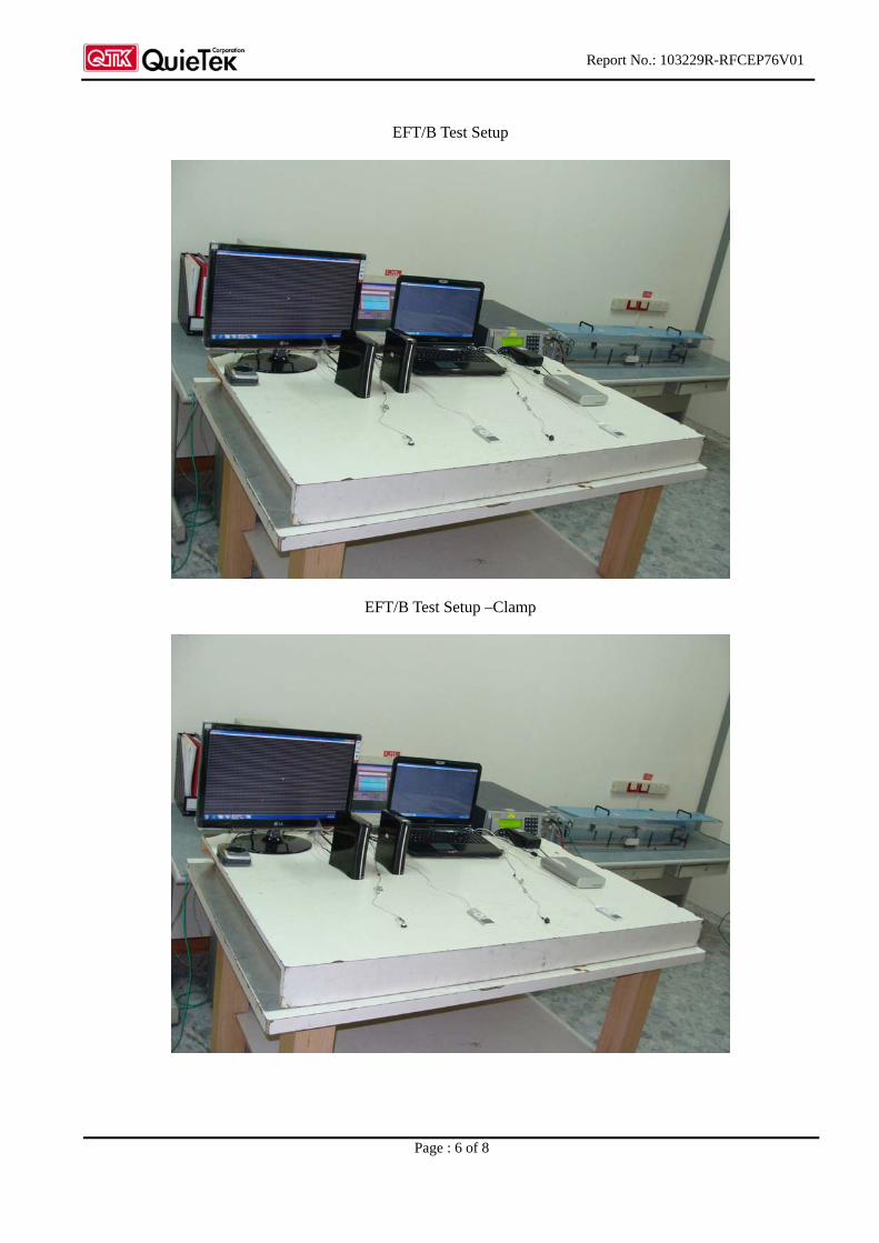
EFT/B Test Setup
EFT/B Test Setup –Clamp

Report No.: 103229R-RFCEP76V01
Page : 7 of 8
SURGE Test Setup
Conducted Susceptibility Test Setup
Report No.: 103229R-RFCEP76V01
Page : 8 of 8
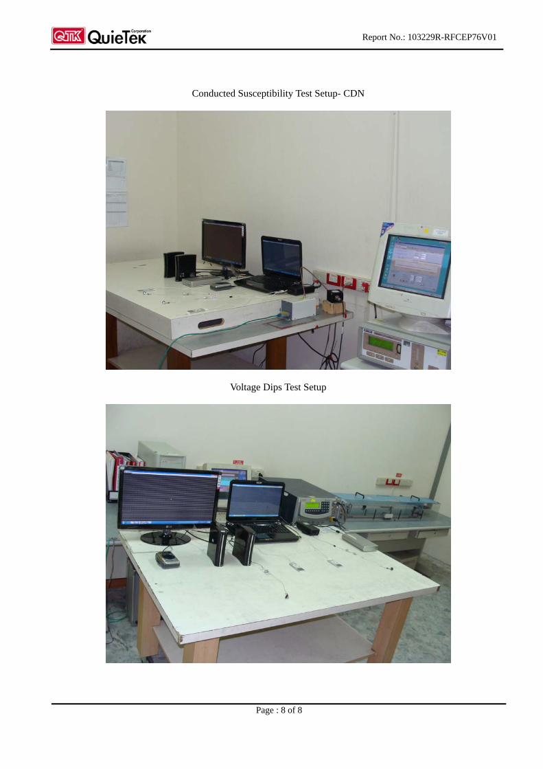
Conducted Susceptibility Test Setup- CDN
Voltage Dips Test Setup

Report No. 103229R-RFCEP76V01
Page: 51 of 51
Attachment 2: EUT Detailed Photographs

Report No.: 103229R-RFCEP76V01
Page : 1 of 10
Attachment 2 : EUT Detailed Photographs
(1) EUT Photo
(2) EUT Photo
Report No.: 103229R-RFCEP76V01
Page : 2 of 10
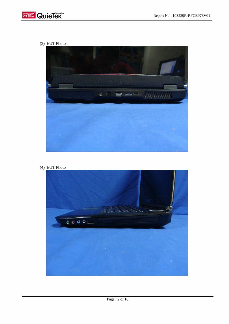
(3) EUT Photo
(4) EUT Photo

Report No.: 103229R-RFCEP76V01
Page : 3 of 10
(5) EUT Photo
(6) EUT Photo
Report No.: 103229R-RFCEP76V01
Page : 4 of 10
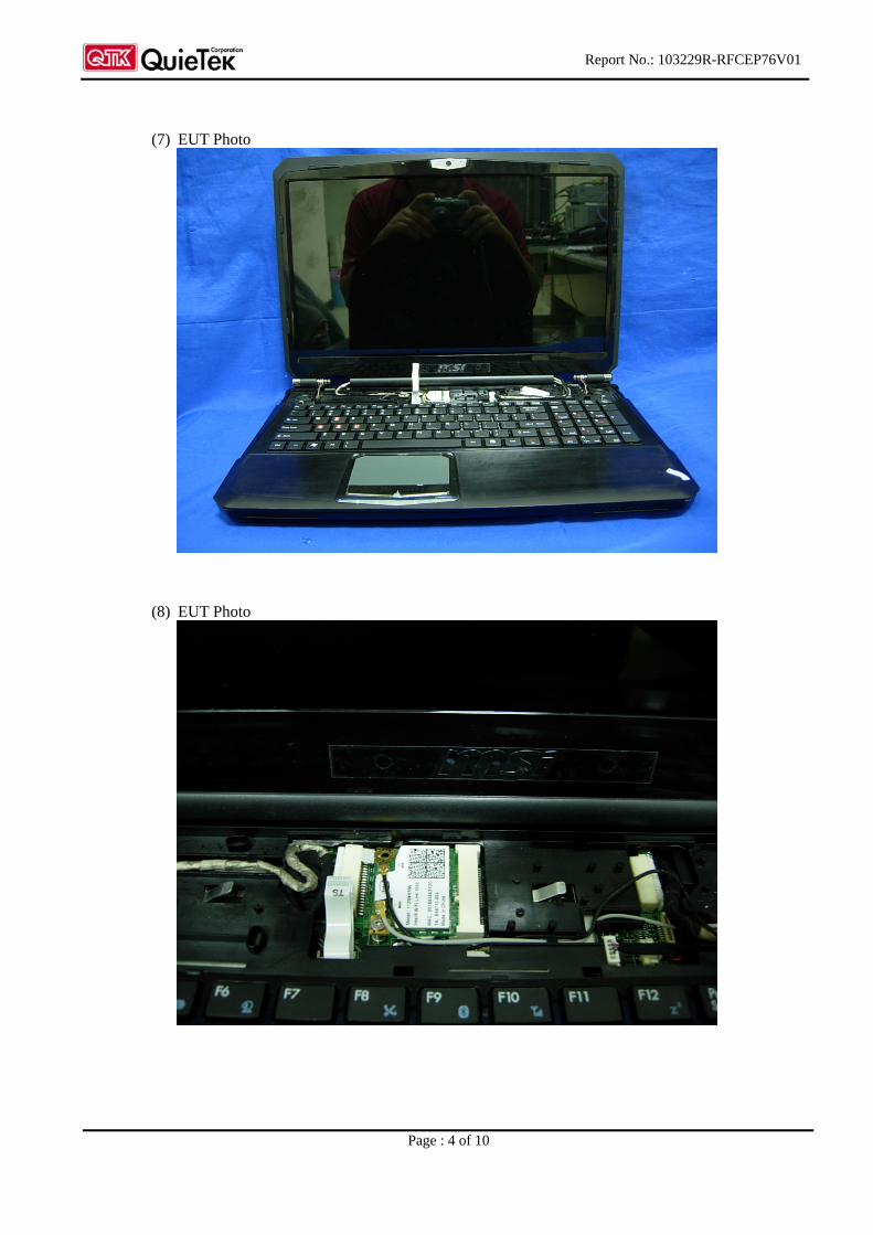
(7) EUT Photo
(8) EUT Photo

Report No.: 103229R-RFCEP76V01
Page : 5 of 10
(9) EUT Photo
(10) EUT Photo

Report No.: 103229R-RFCEP76V01
Page : 6 of 10
(11) EUT Photo
(12) EUT Photo
Report No.: 103229R-RFCEP76V01
Page : 7 of 10
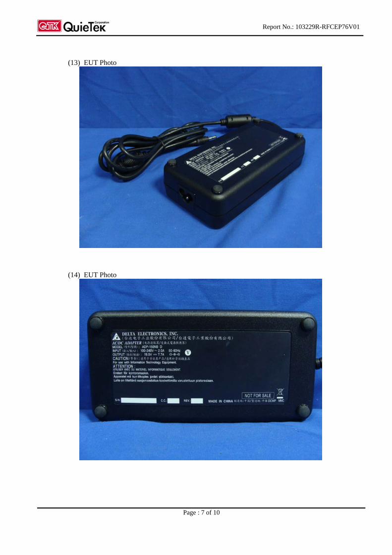
(13) EUT Photo
(14) EUT Photo

Report No.: 103229R-RFCEP76V01
Page : 8 of 10
(15) EUT Photo
(16) EUT Photo

Report No.: 103229R-RFCEP76V01
Page : 9 of 10
(17) EUT Photo
(18) EUT Photo

Report No.: 103229R-RFCEP76V01
Page : 10 of 10
(19) EUT Photo