Embed Size (px)
Citation preview

FCC TEST REPORT Report No. : D362802
SPORTON International Inc. TEL : 886-2-2696-2468
FAX : 886-2-2696-2255
FCC TEST REPORT Authorized under Declaration of Conformity
according to
47 CFR, Part 2, Part 15, Subpart B Class B
Equipment : WIRELESS 11B PCI CARD
Model No. : PC11B2, MS-6828
Filing Type : Declaration of Conformity
Applicant : Micro-Star Int’l Co., Ltd. No. 69, Li-De St., Jung-He City, Taipei Hsien, Taiwan
The test result refers exclusively to the test presented test model / sample. Without written approval of SPORTON International Inc., the test report shall not be reproduced
except in full. Certificate or Test Report must not be used by the applicant to claim the product in this test report
endorsement by NVLAP or any agency of U.S. government.
SPORTON International Inc. 6F, No.106, Sec. 1, Hsin Tai Wu Rd., Hsi Chih, Taipei Hsien, Taiwan, R.O.C.

FCC TEST REPORT Report No. : D362802
SPORTON International Inc. Page No. : i TEL : 886-2-2696-2468 Issued Date : Jul. 18, 2003 FAX : 886-2-2696-2255
Table of Contents
History of this test report ......................................................................................................................... ii CERTIFICATE OF COMPLIANCE.............................................................................................................. 1 1. General Description of Equipment under Test ..................................................................................... 2
1.1 Applicant.......................................................................................................................................................................................2 1.2 Manufacturer.................................................................................................................................................................................2 1.3 Basic Description of Equipment under Test...................................................................................................................................2 1.4 Feature of Equipment under Test..................................................................................................................................................3
2. Test Configuration of Equipment under Test ....................................................................................... 4 2.1 Test Manner..................................................................................................................................................................................4 2.2 Description of Test System...........................................................................................................................................................4 2.3 Connection Diagram of Test System.............................................................................................................................................6
3. Test Software ....................................................................................................................................... 7 4. General Information of Test ................................................................................................................. 8
4.1 Test Facility ...................................................................................................................................................................................8 4.2 Test Voltage..................................................................................................................................................................................8 4.3 Standard for Methods of Measurement.........................................................................................................................................8 4.4 Test in Compliance with................................................................................................................................................................8 4.5 Frequency Range Investigated......................................................................................................................................................8 4.6 Test Distance................................................................................................................................................................................8
5. Test of Conducted Powerline............................................................................................................... 9 5.1 Major Measuring Instruments........................................................................................................................................................9 5.2 Test Procedures ..........................................................................................................................................................................10 5.3 Typical Test Setup Layout of Conducted Powerline....................................................................................................................11 5.4 Test Result of AC Powerline Conducted Emission......................................................................................................................12 5.5 Photographs of Conducted Powerline Test Configuration...........................................................................................................18
6. Test of Radiated Emission ..................................................................................................................20 6.1 Major Measuring Instruments......................................................................................................................................................20 6.2 Test Procedures ..........................................................................................................................................................................21 6.3 Typical Test Setup Layout of Radiated Emission ........................................................................................................................22 6.4 Test Result of Radiated Emission ...............................................................................................................................................23 6.5 Photographs of Radiated Emission Test Configuration...............................................................................................................47
7. Antenna Factor & Cable Loss .............................................................................................................48 8. List of Measuring Equipment Used .....................................................................................................49 9. Uncertainty of Test Site.......................................................................................................................50 10. Certificate of NVLAP Accreditation ...................................................................................................51 Appendix A. Photographs of EUT .................................................................................................. A1 ~ A6

FCC TEST REPORT Report No. : D362802
SPORTON International Inc. Page No. : ii TEL : 886-2-2696-2468 Issued Date : Jul. 18, 2003 FAX : 886-2-2696-2255
History of this test report
Original Report Issue Date: Jul. 18, 2003
■ No additional attachment.
□ Additional attachment were issued as following record:
Attachment No. Issue Date Description

FCC TEST REPORT Report No. : D362802
SPORTON International Inc. Page No. : 1 of 1 TEL : 886-2-2696-2468 Issued Date : Jul. 18, 2003 FAX : 886-2-2696-2255
Certificate No. : D362802
CERTIFICATE OF COMPLIANCE Authorized under Declaration of Conformity
according to
47 CFR, Part 2, Part 15, Subpart B Class B
Equipment : WIRELESS 11B PCI CARD
Model No. : PC11B2, MS-6828
Applicant : Micro-Star Int’l Co., Ltd. No. 69, Li-De St., Jung-He City, Taipei Hsien, Taiwan
I HEREBY CERTIFY THAT:
The measurements shown in this test report were made in accordance with the procedures given in
ANSI C63.4 - 1992 and the energy emitted by this equipment was passed FCC Part 15 in both radiated and
conducted emission class B limits. Testing was carried out on Jul. 03, 2003 at SPORTON International Inc.
LAB.
SPORTON International Inc.
6F, No.106, Sec. 1, Hsin Tai Wu Rd., Hsi Chih, Taipei Hsien, Taiwan, R.O.C.

FCC TEST REPORT Report No. : D362802
SPORTON International Inc. Page No. : 2 of 2 TEL : 886-2-2696-2468 Issued Date : Jul. 18, 2003 FAX : 886-2-2696-2255
1. General Description of Equipment under Test
1.1 Applicant
Micro-Star Int’l Co., Ltd.
No. 69, Li-De St., Jung-He City, Taipei Hsien, Taiwan
1.2 Manufacturer
1. Micro-Star Int’l Co., Ltd.
No. 488, Ban-Nan Rd., Jung-He City, Taipei Hsien, Taiwan
2. MSI COMPUTER (SHENZHEN) Co., Ltd.
Longma Information Technology Industrial Park, Shiyan, Tangtou Village, Shenzhen
1.3 Basic Description of Equipment under Test
Equipment : WIRELESS 11B PCI CARD
Model No. : PC11B2, MS-6828
Trade Name : MSI
RP- SMA Cable : Shielded, 0.5m
RP- SMA Cable : Shielded, 1m
Power Supply Type : From PC
AC Power Cord : N/A

FCC TEST REPORT Report No. : D362802
SPORTON International Inc. Page No. : 3 of 3 TEL : 886-2-2696-2468 Issued Date : Jul. 18, 2003 FAX : 886-2-2696-2255
1.4 Feature of Equipment under Test
General Operating system: Microsoft® Windows® 98SE/ME/2000/XP
Compliance:
- IEEE 802.11b
- WECA Wi-Fi
- WHQL (Windows ME/2000/XP) Physical
Form Factor: 32-bit PCI v2.2
Dimensions (WxDxH): 127.3 X 77.6 X 18.4mm
Antenna: Dipole
Weight: 29g
Operation Voltage: 3.3V Radio Frequency Range: 2.4GHz to 2.4835GHz
Operating Channels:
- 11 channels
- Maximum 3 non-overlapped channels
- 25MHz bandwidth per channel
Data Rate and Modulation Types:
- CCK @ 5.5 and 11Mbps.
- DQPSK @ 2Mbps.
- DBPSK @ 1Mbps.
Wireless Medium: Direct Sequence Spread Spectrum (DSSS) with ACK; Half-Duplex
Media Access Protocol: Carrier Sense Multiple Access with Collision Avoidance (CDMA/CA)
Transmitter Output Power: 15dBm Performance Range: Up to 150m. Security
Security Mechanism:
- 64-/128-bit WEP
- IEEE802.11i TKIP

FCC TEST REPORT Report No. : D362802
SPORTON International Inc. Page No. : 4 of 4 TEL : 886-2-2696-2468 Issued Date : Jul. 18, 2003 FAX : 886-2-2696-2255
2. Test Configuration of Equipment under Test
2.1 Test Manner
a. The EUT has been associated with personal computer and peripherals pursuant to ANSI C63.4-1992
and configuration operated in a manner which tended to maximize its emission characteristics in a
typical application.
b. The complete test system included COMPAQ PC, VIEWSONIC Monitor, LOGITECH PS/2 Keyboard,
LOGITECH PS/2 Mouse, EPSON Printer, ACEEX Modem and EUT for EMI test.
c. The EUT equipped five types of antenna, the following modes were pretested:
1. CH01 (2412MHz), RP-SMA Cable: 0.5m
2. CH01 (2412MHz), RP-SMA Cable: 1m
cause “0.5m antenna cable” generated the worst test result, it was selected to measured the other two
channels (one near middle and one near bottom), according to 15.31(m), as following:
Mode 1. CH01 (2412MHz), RP-SMA cable: 0.5m
Mode 2. CH06 (2437MHz), RP-SMA cable: 0.5m
Mode 3. CH11 (2462MHz), RP-SMA cable: 0.5m
d. Frequency range investigated: conduction 150 KHz to 30 MHz, radiation 30 MHz to 24835MHz.
2.2 Description of Test System
Support Unit 1. -- Monitor (VIEWSONIC)
FCC ID : N/A
Model No. : VCDTS21553-3P
Power Supply Type : Switching
Power Cord : Non-Shielded
Serial No. : SP0051
Data Cable : Shielded, 1.7m
Remark : This support device was tested to compy with FCC standards and
authorized under a declaration of conformity
Support Unit 2. -- PS/2 Keyboard (LOGITECH)
FCC ID : N/A
Model No. : Y-SJ17
Serial No. : SP0054
Data Cable : Shielded, 1.7m
Remark : This support device was tested to comply with FCC standards and
authorized under a declaration of conformity.

FCC TEST REPORT Report No. : D362802
SPORTON International Inc. Page No. : 5 of 5 TEL : 886-2-2696-2468 Issued Date : Jul. 18, 2003 FAX : 886-2-2696-2255
Support Unit 3. – PS/2 Mouse (LOGITECH)
FCC ID : DZL211029
Model No. : M-S34
Serial No. : SP0041
Data Cable : Shielded, 1.7m
Support Unit 4. -- Printer (EPSON)
FCC ID : N/A
Model No. : STYLUS COLRO S680
Power Supply Type : Linear
Power Cord : Non-Shielded
Serial No. : SP0048
Data Cable : Shielded, 1.35m
Remark : This support device was tested to comply with FCC standards and
authorized under a declaration of conformity.
Support Unit 5. -- Modem (ACEEX)
FCC ID : IFAXDM1414
Model No. : DM1414
Power Supply Type : Linear
Power Cord : Non-Shielded
Serial No. : SP0015
Data Cable : Shielded, 1.15m
Support Unit 6. – Personal Computer (COMPAQ)
FCC ID : N/A
Model No. : Evo D380mx
Power Supply Type : Switching
Power Cord : Non-Shielded
Serial No. : SP0036
Remark : This support device was tested to comply with FCC standards and
authorized under a declaration of conformity.

FCC TEST REPORT Report No. : D362802
SPORTON International Inc. Page No. : 6 of 6 TEL : 886-2-2696-2468 Issued Date : Jul. 18, 2003 FAX : 886-2-2696-2255
2.3 Connection Diagram of Test System
2
1
PC
PS/2 Mouse
Monitor
4
3
Modem
PS/2 Keyboard
Printer6
5
Antenna
1. The I/O cable is connected from PC to the support unit 1.
2. The I/O cable is connected from PC to the support unit 2.
3. The I/O cable is connected from PC to the support unit 3.
4. The I/O cable is connected from PC to the support unit 4.
5. The I/O cable is connected from PC to the support unit 5.
6. The RP- SMA cable is connected from EUT to the Antenna.

FCC TEST REPORT Report No. : D362802
SPORTON International Inc. Page No. : 7 of 7 TEL : 886-2-2696-2468 Issued Date : Jul. 18, 2003 FAX : 886-2-2696-2255
3. Test Software
An executive program, EMCTEST.EXE under WIN XP, which generates a complete line of continuously
repeating “ H “ pattern was used as the test software.
The program was executed as follows:
a. Turn on the power of all equipment.
b. The PC reads the test program from the hard disk drive and runs it.
c. The PC sends “ H“ messages to the monitor, and the monitor displays “ H “ patterns on the screen.
d. The PC sends “ H “ messages to the printer, then the printer prints them on the paper.
e. The PC sends “ H “ messages to the modem.
f. The PC sends “ H ” messages to the internal Hard Disk, and the Hard Disk reads and writes the
message.
g. Repeat the steps from c to f.
At the same time, “QA Test” was executed to keep transmitting signals at fixed frequency.

FCC TEST REPORT Report No. : D362802
SPORTON International Inc. Page No. : 8 of 8 TEL : 886-2-2696-2468 Issued Date : Jul. 18, 2003 FAX : 886-2-2696-2255
4. General Information of Test
4.1 Test Facility
Test Site Location : No. 52, Hwa Ya 1st Rd., Hwa Ya Technology Park,
Kwei-Shan Hsiag, Tao Yuan Hsien, Taiwan, R.O.C.
TEL : 886-3-327-3456
FAX : 886-3-318-0055
Test Site No. : CO01-HY, 10CH02-HY
4.2 Test Voltage
110V/60Hz
4.3 Standard for Methods of Measurement
ANSI C63.4-1992
4.4 Test in Compliance with
FCC Part 15, Subpart B, Class B
4.5 Frequency Range Investigated
a. Conduction: from 150 kHz to 30 MHz
b. Radiation: from 30 MHz to 24,835 MHz
4.6 Test Distance
The test distance of radiated emission from antenna to EUT is 3M.

FCC TEST REPORT Report No. : D362802
SPORTON International Inc. Page No. : 9 of 9 TEL : 886-2-2696-2468 Issued Date : Jul. 18, 2003 FAX : 886-2-2696-2255
5. Test of Conducted Powerline
Conducted Emissions were measured from 150 kHz to 30 MHz with a bandwidth of 9 KHz and return leads
of the EUT according to the methods defined in ANSI C63.4-1992 Section 3.1. The EUT was placed on a
nonmetallic stand in a shielded room 0.8 meters above the ground plane as shown in section 5.3. The
interface cables and equipment positioning were varied within limits of reasonable applications to determine
the position produced maximum conducted emissions.
5.1 Major Measuring Instruments
l Test Receiver (R&S ESCS 30)
Attenuation 10 dB
Start Frequency 0.15 MHz
Stop Frequency 30 MHz
IF Bandwidth 9 KHz

FCC TEST REPORT Report No. : D362802
SPORTON International Inc. Page No. : 10 of 10 TEL : 886-2-2696-2468 Issued Date : Jul. 18, 2003 FAX : 886-2-2696-2255
5.2 Test Procedures
a. The EUT was placed 0.4 meter from the conducting wall of the shielding room was kept at least 80
centimeters from any other grounded conducting surface.
b. Connect EUT to the power mains through a line impedance stabilization network (LISN).
c. All the support units are connect to the other LISN.
d. The LISN provides 50 ohm coupling impedance for the measuring instrument.
e. The FCC states that a 50 ohm, 50 microhenry LISN should be used.
f. Both sides of AC line were checked for maximum conducted interference.
g. The frequency range from 150 kHz to 30 MHz was searched.
h. Set the test-receiver system to Peak Detect Function and Specified Bandwidth with Maximum Hold
Mode.

FCC TEST REPORT Report No. : D362802
SPORTON International Inc. Page No. : 11 of 11 TEL : 886-2-2696-2468 Issued Date : Jul. 18, 2003 FAX : 886-2-2696-2255
5.3 Typical Test Setup Layout of Conducted Powerline
L.I.S.N.
10 cm
80 cm to the ground plane
L.I.S.N.

FCC TEST REPORT Report No. : D362802
SPORTON International Inc. Page No. : 12 of 12 TEL : 886-2-2696-2468 Issued Date : Jul. 18, 2003 FAX : 886-2-2696-2255
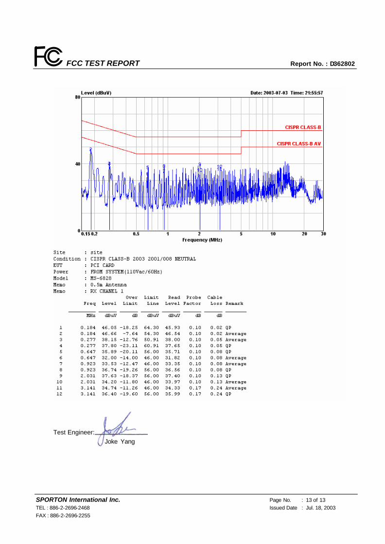
5.4 Test Result of AC Powerline Conducted Emission
5.4.1 Test Mode: Mode 1
Frequency Range of Test: from 0.15 MHz to 30 MHz
Temperature: 30.4 °C
Relative Humidity: 52 %
All emissions not reported here are more than 10 dB below the prescribed limit. ■ The test was passed at the minimum margin that marked by a frame in the following data
FCC TEST REPORT Report No. : D362802
SPORTON International Inc. Page No. : 13 of 13 TEL : 886-2-2696-2468 Issued Date : Jul. 18, 2003 FAX : 886-2-2696-2255
Test Engineer: Joke Yang

FCC TEST REPORT Report No. : D362802
SPORTON International Inc. Page No. : 14 of 14 TEL : 886-2-2696-2468 Issued Date : Jul. 18, 2003 FAX : 886-2-2696-2255
5.4.2 Test Mode: Mode 2
Frequency Range of Test: from 0.15 MHz to 30 MHz
Temperature: 30.4 °C
Relative Humidity: 52 %
All emissions not reported here are more than 10 dB below the prescribed limit. ■ The test was passed at the minimum margin that marked by a frame in the following data

FCC TEST REPORT Report No. : D362802
SPORTON International Inc. Page No. : 15 of 15 TEL : 886-2-2696-2468 Issued Date : Jul. 18, 2003 FAX : 886-2-2696-2255
Test Engineer: Joke Yang

FCC TEST REPORT Report No. : D362802
SPORTON International Inc. Page No. : 16 of 16 TEL : 886-2-2696-2468 Issued Date : Jul. 18, 2003 FAX : 886-2-2696-2255
5.4.3 Test Mode: Mode 3
Frequency Range of Test: from 0.15 MHz to 30 MHz
Temperature: 30.4 °C
Relative Humidity: 52 %
All emissions not reported here are more than 10 dB below the prescribed limit. ■ The test was passed at the minimum margin that marked by a frame in the following data

FCC TEST REPORT Report No. : D362802
SPORTON International Inc. Page No. : 17 of 17 TEL : 886-2-2696-2468 Issued Date : Jul. 18, 2003 FAX : 886-2-2696-2255
Test Engineer: Joke Yang

FCC TEST REPORT Report No. : D362802
SPORTON International Inc. Page No. : 18 of 18 TEL : 886-2-2696-2468 Issued Date : Jul. 18, 2003 FAX : 886-2-2696-2255
5.5 Photographs of Conducted Powerline Test Configuration
l The photographs show the configuration that generates the maximum emission.
FRONT VIEW
REAR VIEW

FCC TEST REPORT Report No. : D362802
SPORTON International Inc. Page No. : 19 of 19 TEL : 886-2-2696-2468 Issued Date : Jul. 18, 2003 FAX : 886-2-2696-2255
SIDE VIEW

FCC TEST REPORT Report No. : D362802
SPORTON International Inc. Page No. : 20 of 20 TEL : 886-2-2696-2468 Issued Date : Jul. 18, 2003 FAX : 886-2-2696-2255
6. Test of Radiated Emission
Radiated emissions from 30 MHz to 24,800 MHz were measured with a bandwidth of 120 kHz for
30MHz-1000MHz, 1 MHz for above 1GHz according to the methods defines in ANSI C63.4-1992. The EUT
was placed on a nonmetallic stand, 0.8 meter above the ground plane, as shown in section 6.3. The
interface cables and equipment positions were varied within limits of reasonable applications to determine
the positions producing maximum radiated emissions.
6.1 Major Measuring Instruments
l Amplifier (SCHAFFNER CPA9231A)
RF Gain 30 dB Signal Input 9 KHz to 2 GHz
l Spectrum Analyzer (R&S FSP7)
Attenuation 10 dB
Start Frequency 30 MHz
Stop Frequency 1000 MHz
Resolution Bandwidth 120 KHz for below 1GHz
1 MHz for above 1GHz
Signal Input 9 KHz to 7 GHz
l Test Receiver (R&S ESI7)
Attenuation 10 dB
Start Frequency 30 MHz
Stop Frequency 1000 MHz
Resolution Bandwidth 120 KHz for below 1GHz
1 MHz for above 1GHz
Signal Input 20 Hz to 7 GHz
FCC TEST REPORT Report No. : D362802
SPORTON International Inc. Page No. : 21 of 21 TEL : 886-2-2696-2468 Issued Date : Jul. 18, 2003 FAX : 886-2-2696-2255
6.2 Test Procedures
a. The EUT was placed on a rotatable table top 0.8 meter above ground.
b. The EUT was set 3 meters from the interference receiving antenna which was mounted on the top of a
variable height antenna tower.
c. The table was rotated 360 degrees to determine the position of the highest radiation.
d. The antenna is a half wave dipole and its height is varied between one meter and four meters above
ground to find the maximum value of the field strength both horizontal polarization and vertical
polarization of the antenna are set to make the measurement.
e. For each suspected emission the EUT was arranged to its worst case and then tune the antenna tower
(from 1 M to 4 M) and turn table (from 0 degree to 360 degrees) to find the maximum reading.
f. Set the test-receiver system to Peak Detect Function and specified bandwidth with Maximum Hold
Mode.
g. If the emission level of the EUT in peak mode was 3 dB lower than the limit specified, then testing will be
stopped and peak values of EUT will be reported, otherwise, the emissions which do not have 3 dB
margin will be repeated one by one using the quasi-peak method and reported.
h. For testing above 1GHz, the emission level of the EUT in peak mode was 20dB lower than average limit
(that means the emission level in peak mode also complies with the limit in average mode), then testing
will be stopped and peak values of EUT will be reported, otherwise, the emissions will be measured in
average mode again and reported.

FCC TEST REPORT Report No. : D362802
SPORTON International Inc. Page No. : 22 of 22 TEL : 886-2-2696-2468 Issued Date : Jul. 18, 2003 FAX : 886-2-2696-2255
6.3 Typical Test Setup Layout of Radiated Emission
Antenna
0.8 M
Equipment under Test
Test distance
TurnTable
Ground Plane
Receiver

FCC TEST REPORT Report No. : D362802
SPORTON International Inc. Page No. : 23 of 23 TEL : 886-2-2696-2468 Issued Date : Jul. 18, 2003 FAX : 886-2-2696-2255
6.4 Test Result of Radiated Emission
6.4.1 Test Mode: Mode 1
Test Distance: 3M
Temperature: 26°C
Relative Humidity: 63 %
Emission level (dBuV/m) = 20 log Emission level (uV/m)
Corrected Reading: Antenna Factor + Cable Loss + Read Level - Preamp Factor = Level
■ The test was passed at the minimum margin that marked by the frame in the following test record

FCC TEST REPORT Report No. : D362802
SPORTON International Inc. Page No. : 24 of 24 TEL : 886-2-2696-2468 Issued Date : Jul. 18, 2003 FAX : 886-2-2696-2255

FCC TEST REPORT Report No. : D362802
SPORTON International Inc. Page No. : 25 of 25 TEL : 886-2-2696-2468 Issued Date : Jul. 18, 2003 FAX : 886-2-2696-2255

FCC TEST REPORT Report No. : D362802
SPORTON International Inc. Page No. : 26 of 26 TEL : 886-2-2696-2468 Issued Date : Jul. 18, 2003 FAX : 886-2-2696-2255

FCC TEST REPORT Report No. : D362802
SPORTON International Inc. Page No. : 27 of 27 TEL : 886-2-2696-2468 Issued Date : Jul. 18, 2003 FAX : 886-2-2696-2255

FCC TEST REPORT Report No. : D362802
SPORTON International Inc. Page No. : 28 of 28 TEL : 886-2-2696-2468 Issued Date : Jul. 18, 2003 FAX : 886-2-2696-2255

FCC TEST REPORT Report No. : D362802
SPORTON International Inc. Page No. : 29 of 29 TEL : 886-2-2696-2468 Issued Date : Jul. 18, 2003 FAX : 886-2-2696-2255

FCC TEST REPORT Report No. : D362802
SPORTON International Inc. Page No. : 30 of 30 TEL : 886-2-2696-2468 Issued Date : Jul. 18, 2003 FAX : 886-2-2696-2255
Ø For 5GHz ~ 25GHz Remark: Frequency from 5000MHz to 25000MHz, the emission emitted by the EUT is too low to be
measured
Test Engineer: Jay Zhong

FCC TEST REPORT Report No. : D362802
SPORTON International Inc. Page No. : 31 of 31 TEL : 886-2-2696-2468 Issued Date : Jul. 18, 2003 FAX : 886-2-2696-2255
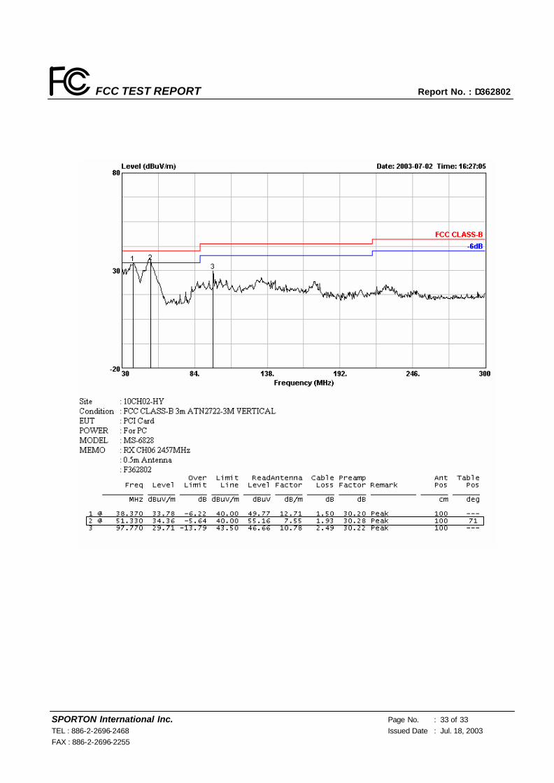
6.4.2 Test Mode: Mode 2
Test Distance: 3M
Temperature: 26°C
Relative Humidity: 63 %
Emission level (dBuV/m) = 20 log Emission level (uV/m)
Corrected Reading: Antenna Factor + Cable Loss + Read Level - Preamp Factor = Level
■ The test was passed at the minimum margin that marked by the frame in the following test record

FCC TEST REPORT Report No. : D362802
SPORTON International Inc. Page No. : 32 of 32 TEL : 886-2-2696-2468 Issued Date : Jul. 18, 2003 FAX : 886-2-2696-2255
FCC TEST REPORT Report No. : D362802
SPORTON International Inc. Page No. : 33 of 33 TEL : 886-2-2696-2468 Issued Date : Jul. 18, 2003 FAX : 886-2-2696-2255

FCC TEST REPORT Report No. : D362802
SPORTON International Inc. Page No. : 34 of 34 TEL : 886-2-2696-2468 Issued Date : Jul. 18, 2003 FAX : 886-2-2696-2255

FCC TEST REPORT Report No. : D362802
SPORTON International Inc. Page No. : 35 of 35 TEL : 886-2-2696-2468 Issued Date : Jul. 18, 2003 FAX : 886-2-2696-2255

FCC TEST REPORT Report No. : D362802
SPORTON International Inc. Page No. : 36 of 36 TEL : 886-2-2696-2468 Issued Date : Jul. 18, 2003 FAX : 886-2-2696-2255

FCC TEST REPORT Report No. : D362802
SPORTON International Inc. Page No. : 37 of 37 TEL : 886-2-2696-2468 Issued Date : Jul. 18, 2003 FAX : 886-2-2696-2255

FCC TEST REPORT Report No. : D362802
SPORTON International Inc. Page No. : 38 of 38 TEL : 886-2-2696-2468 Issued Date : Jul. 18, 2003 FAX : 886-2-2696-2255
Ø For 5GHz ~ 25GHz Remark: Frequency from 5000MHz to 25000MHz, the emission emitted by the EUT is too low to be
measured
Test Engineer: Jay Zhong

FCC TEST REPORT Report No. : D362802
SPORTON International Inc. Page No. : 39 of 39 TEL : 886-2-2696-2468 Issued Date : Jul. 18, 2003 FAX : 886-2-2696-2255
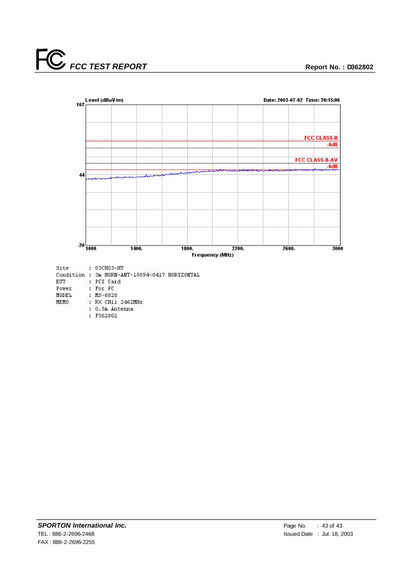
6.4.3 Test Mode: Mode 3
Test Distance: 3M
Temperature: 26°C
Relative Humidity: 63 %
Emission level (dBuV/m) = 20 log Emission level (uV/m)
Corrected Reading: Antenna Factor + Cable Loss + Read Level - Preamp Factor = Level
■ The test was passed at the minimum margin that marked by the frame in the following test record

FCC TEST REPORT Report No. : D362802
SPORTON International Inc. Page No. : 40 of 40 TEL : 886-2-2696-2468 Issued Date : Jul. 18, 2003 FAX : 886-2-2696-2255

FCC TEST REPORT Report No. : D362802
SPORTON International Inc. Page No. : 41 of 41 TEL : 886-2-2696-2468 Issued Date : Jul. 18, 2003 FAX : 886-2-2696-2255

FCC TEST REPORT Report No. : D362802
SPORTON International Inc. Page No. : 42 of 42 TEL : 886-2-2696-2468 Issued Date : Jul. 18, 2003 FAX : 886-2-2696-2255
FCC TEST REPORT Report No. : D362802
SPORTON International Inc. Page No. : 43 of 43 TEL : 886-2-2696-2468 Issued Date : Jul. 18, 2003 FAX : 886-2-2696-2255

FCC TEST REPORT Report No. : D362802
SPORTON International Inc. Page No. : 44 of 44 TEL : 886-2-2696-2468 Issued Date : Jul. 18, 2003 FAX : 886-2-2696-2255

FCC TEST REPORT Report No. : D362802
SPORTON International Inc. Page No. : 45 of 45 TEL : 886-2-2696-2468 Issued Date : Jul. 18, 2003 FAX : 886-2-2696-2255

FCC TEST REPORT Report No. : D362802
SPORTON International Inc. Page No. : 46 of 46 TEL : 886-2-2696-2468 Issued Date : Jul. 18, 2003 FAX : 886-2-2696-2255
Ø For 5GHz ~ 25GHz Remark: Frequency from 5000MHz to 25000MHz, the emission emitted by the EUT is too low to be
measured
Test Engineer: Jay Zhong

FCC TEST REPORT Report No. : D362802
SPORTON International Inc. Page No. : 47 of 47 TEL : 886-2-2696-2468 Issued Date : Jul. 18, 2003 FAX : 886-2-2696-2255
6.5 Photographs of Radiated Emission Test Configuration
l The photographs show the configuration that generates the maximum emission.
FRONT VIEW
REAR VIEW
FCC TEST REPORT Report No. : D362802
SPORTON International Inc. Page No. : 48 of 48 TEL : 886-2-2696-2468 Issued Date : Jul. 18, 2003 FAX : 886-2-2696-2255
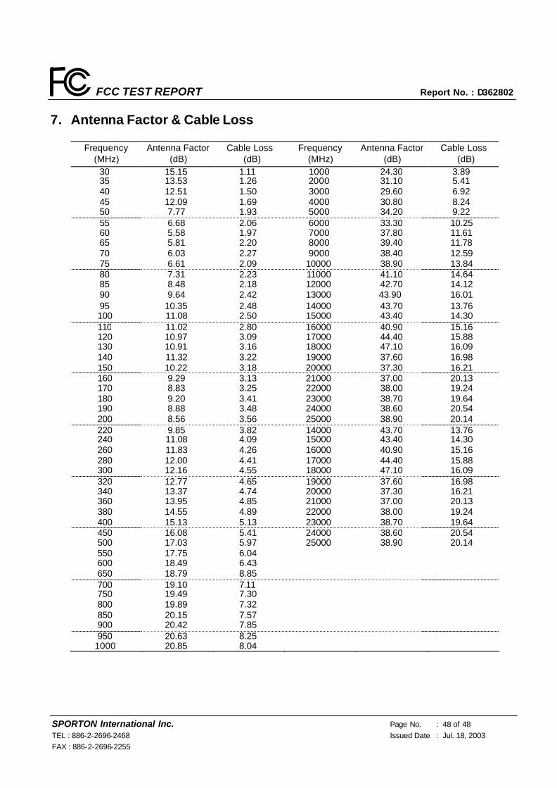
7. Antenna Factor & Cable Loss
Frequency (MHz)
Antenna Factor (dB)
Cable Loss (dB)
Frequency (MHz)
Antenna Factor (dB)
Cable Loss (dB)
30 15.15 1.11 1000 24.30 3.89 35 13.53 1.26 2000 31.10 5.41 40 12.51 1.50 3000 29.60 6.92 45 12.09 1.69 4000 30.80 8.24 50 7.77 1.93 5000 34.20 9.22 55 6.68 2.06 6000 33.30 10.25 60 5.58 1.97 7000 37.80 11.61 65 5.81 2.20 8000 39.40 11.78 70 6.03 2.27 9000 38.40 12.59 75 6.61 2.09 10000 38.90 13.84 80 7.31 2.23 11000 41.10 14.64 85 8.48 2.18 12000 42.70 14.12 90 9.64 2.42 13000 43.90 16.01 95 10.35 2.48 14000 43.70 13.76 100 11.08 2.50 15000 43.40 14.30 110 11.02 2.80 16000 40.90 15.16 120 10.97 3.09 17000 44.40 15.88 130 10.91 3.16 18000 47.10 16.09 140 11.32 3.22 19000 37.60 16.98 150 10.22 3.18 20000 37.30 16.21 160 9.29 3.13 21000 37.00 20.13 170 8.83 3.25 22000 38.00 19.24 180 9.20 3.41 23000 38.70 19.64 190 8.88 3.48 24000 38.60 20.54 200 8.56 3.56 25000 38.90
91 20.14
220 9.85 3.82 14000 43.70 13.76 240 11.08 4.09 15000 43.40 14.30 260 11.83 4.26 16000 40.90 15.16 280 12.00 4.41 17000 44.40 15.88 300 12.16 4.55 18000 47.10 16.09 320 12.77 4.65 19000 37.60 16.98 340 13.37 4.74 20000 37.30 16.21 360 13.95 4.85 21000 37.00 20.13 380 14.55 4.89 22000 38.00 19.24 400 15.13 5.13 23000 38.70 19.64 450 16.08 5.41 24000 38.60 20.54 500 17.03 5.97 25000 38.90
91 20.14
550 17.75 6.04 600 18.49 6.43 650 18.79 8.85 700 19.10 7.11 750 19.49 7.30 800 19.89 7.32 850 20.15 7.57 900 20.42 7.85 950 20.63 8.25
1000 20.85 8.04

FCC TEST REPORT Report No. : D362802
SPORTON International Inc. Page No. : 49 of 49 TEL : 886-2-2696-2468 Issued Date : Jul. 18, 2003 FAX : 886-2-2696-2255
8. List of Measuring Equipment Used
Instrument Manufacturer Model No. Serial No. Characteristics Calibration Date Remark
EMC Receiver R&S ESCS 30 100132 9 KHz – 2.75 GHz Jun. 12, 2003 Conduction (CO01-HY)
LISN MessTec NNB-2/16Z 2001-008 9 KHz – 30 MHz Apr. 29, 2003 Conduction (CO01-HY)
LISN (Support Unit)
MessTec NNB-2/16Z 2001-009 9 KHz – 30 MHz Apr. 29, 2003 Conduction (CO01-HY)
EMI Filter LINDGREN LRE-2060 1004 < 450 Hz N/A Conduction (CO01-HY)
EMI Filter LINDGREN N6006 201052 0 ~ 60 Hz N/A Conduction (CO01-HY)
RF Cable-CON Suhner Switzerland RG223/U CB029 9KHz~30MHz Jan. 07, 2003 Conduction (CO01-HY)
50 ohm BNC type Terminal
NOBLE 50ohm TM009 50 ohm Apr. 24, 2003 Conduction (CO01-HY)
10m Semi Anechoic Chamber
TDK SAC-10M 10CH02-HY 30MHz~1GHz
10m,3m Mar. 15, 2003
Radiation (10CH02-HY)
Spectrum Analyzer R&S FSP7 100644/007 9KHz – 7GHz May 26, 2003 Radiation
(10CH02-HY)
Receiver R&S ESI7 838496/008 20Hz – 7GHz Feb. 11, 2003 Radiation
(10CH02-HY)
Biconical Antenna SCHWARZBECK VHBB 9124 287 30MHz –200MHz Jan. 09, 2003 Radiation
(10CH02-HY)
Log Antenna SCHWARZBECK VUSLP 9111 207 200MHz -1GHz Jan. 09, 2003 Radiation
(10CH02-HY)
Amplifier SCHAFFNER CPA9231A 3565 9KHz – 2GHz Aug. 13, 2002 Radiation
(10CH02-HY)
Amplifier SCHAFFNER CPA9231A 3566 9KHz – 2GHz Aug. 13, 2002 Radiation
(10CH02-HY)
Turn Table HD DS 430 430/360 0 ∼ 360 degree N/A Radiation
(10CH02-HY)
Antenna Mast HD MA240 240/664 1 m - 4 m N/A Radiation
(10CH02-HY)
Antenna Mast HD MA240 240/667 1 m - 4 m N/A Radiation
(10CH02-HY)
RF Cable-R10m Jye Bao RG142 CB027-INSIDE 30MHz~1GHz Jan. 08, 2003 Radiation
(10CH02-HY)
RF Cable-R10m Suhner Switzerland
+ BELDEN RG223/U +
RG8/U CB026-DOOR 30MHz~1GHz Jan. 08, 2003
Radiation (10CH02-HY)
※ Calibration Interval of instruments listed above is one year.

FCC TEST REPORT Report No. : D362802
SPORTON International Inc. Page No. : 50 of 50 TEL : 886-2-2696-2468 Issued Date : Jul. 18, 2003 FAX : 886-2-2696-2255
9. Uncertainty of Test Site
Uncertainty of Radiated Emission Measurement
Contribution Probability
Distribution 3m 10m
Antenna factor calibration normal(k=2) ±1 ±1
cable loss calibration normal(k=2) ±0.3 ±0.3
RCV/SPA specification rectangular ±2 ±2
Antenna Directivity rectangular ±3 ±0.5
Antenna Factor V.S. Height rectangular ±2 ±2
Antenna Factor Interpolation for Frequency rectangular ±0.25 ±0.25
site imperfection rectangular ±2 ±2
Mismatch
Receiver VSWR Γ1=0.09
Antenna VSWR Γ2=0.67
Uncertainty=20log(1-Γ1*Γ2)
U-shaped
±0.54
±0.54
combined standard uncertainty Ue(y) normal ±2.7 ±2.2
Measuring uncertainty for a level of confidence of
95% U=2Ue(y) normal (k=2) ±5.4 ±4.4
U=√{(1/2)²+(0.3/2)²+(2²+0.5²+2²+0.25²+2²)/3+(0.54)²/ 2}=2.2 for 10m test distance
U=√{(1/2)²+(0.3/2)²+(2²+3²+2²+0.25²+2²)/3+(0.54)²/2}=2.7 for 3m test distance
Uncertainty of Conducted Emission Measurement
Contribution Probability
Distribution 150KHz – 30MHz
Cable and I/P attenuator calibration normal(k=2) ±0.3
RCV/SPA specification rectangular ±2
LISN coupling specification rectangular ±1.5
Transducer factor frequency interpolation rectangular ±0.2
Mismatch
Receiver VSWR Γ1=0.09
LISN VSWR Γ2=0.33
Uncertainty=20log(1-Γ1*Γ2)
U-shaped
0.2
combined standard uncertainty Ue(y) normal ±1.66
Measuring uncertainty for a level of confidence of
95% U=2Ue(y) normal (k=2) ±3.32
U=√{(0.3/2)² +(2²+1.5²+0.2²)/3+(0.2)²/2}=1.66

FCC TEST REPORT Report No. : D362802
SPORTON International Inc. Page No. : 51 of 51 TEL : 886-2-2696-2468 Issued Date : Jul. 18, 2003 FAX : 886-2-2696-2255
10. Certificate of NVLAP Accreditation