Embed Size (px)
Citation preview
TECHNICAL PAPER 183
Y:\TECHNICAL PAPERS\TP 181-190\TP 183\TP 183.doc 2006-10
CONTROL OF COPPER ELECTROLYTE IMPURITIES – OVERVIEW OF THE SHORT BED ION EXCHANGE TECHNIQUE AND
PHELPS DODGE EL PASO CASE STUDY
Mike Sheedy and Paul Pajunen Eco-Tec Inc.
1145 Squires Beach Road Pickering, Ontario, Canada L1W 3T9
[email protected] [email protected]
Brad Wesstrom
Phelps Dodge Refining Company 6999 North Loop Road
El Paso, Texas, USA 79915 [email protected]
ABSTRACT
This paper discusses the short bed ion exchange technique for the removal of metal contaminants from copper electrolyte bleed streams. Processes for the selective removal of sulfuric acid, arsenic, antimony, bismuth, and iron will be discussed. A case study outlining the performance history of a short bed system for sulfuric acid removal followed by a two stage selective precipitation system producing a nickel carbonate by-product at the Phelps Dodge Mining Company El Paso operation will be presented.
TECHNICAL PAPER 183
Y:\TECHNICAL PAPERS\TP 181-190\TP 183\TP 183.doc 2006-10
SHORT BED ION EXCHANGE
The short bed ion exchange process has been extensively used in the metal finishing industries since the early 1970’s (1,2). More recently, short bed systems have been sold to primary metals producers for the separation of sulfuric acid from Cu refinery bleed streams (3) and for the recovery of nickel and cobalt from plant effluent streams. This unique technology optimizes the ion exchange process and offers a number of significant advantages over conventional ion exchange. The principal features and benefits of this technology are presented below. Fine Mesh Resins Short bed systems resin beads with much smaller diameters than conventional ion exchangers. Reducing the size greatly improves the exchange kinetics. This allows operation at higher flowrates and reduces the length of the mass transfer zone. This is particularly important for chelating resins, which have very slow exchange kinetics. Work by Price (4) indicates that the exchange rate is inversely proportional to the square of the particle diameter. Thus, halving the particle size increases the exchange rate by 400%. The higher flowrates such an increase permits significantly reduces the volume of resin required. This is particularly important when using expensive chelating resins. Finer particles also aid in fluid displacement which allows a reduction in rinse volume requirements. Short Depth Resin Beds During the operation of a fixed bed process exchange takes place only in the fraction of the bed occupied by the mass transfer zone. Upstream the resin has been exhausted, while downstream the resin remains in the regenerated form. Thus, in a conventional column the majority of the resin is inactive. The short bed process reduces the depths of these inactive regions and makes more effective use of the remaining resin. It should also be noted that the increased kinetics reduce the depth of the mass transfer zone to 0.15 - 0.61m. Counter-Current Regeneration Counter-current regeneration introduces the regenerant into the resin bed in the direction opposite to the feed solution. This technique is a well known chemical engineering principle which in this case, helps to reduce the amount of regenerant required, maximizes the concentration of the recovered metal or acid and ensures complete regeneration minimizing leakage.
TECHNICAL PAPER 183
Y:\TECHNICAL PAPERS\TP 181-190\TP 183\TP 183.doc 2006-10
Fully Packed Bed In a short bed the vessel is completely packed with resin leaving no freeboard. In a conventional column, mixing of the various solutions being processed occurs in the freeboard space. The resulting dilution is very undesirable when processing concentrated solutions. A packed bed eliminates this dilution and also helps to maintain the concentration profiles developed within the resin bed.
ACID SEPARATION
Short bed technology has been adapted to acid separation and is provided as an acid purification unit, APU. This process uses ion exchange resins that selectively absorb free acid but reject dissolved metal salts. The absorbed acid can be removed by passing water over resin. While the use of a specific type of ion exchange resin is required the process is strictly speaking not ion exchange. The acid is not exchanged onto a specific site and the process capacity is not limited by the resins ion exchange capacity.
Typically only a small volume of solution, less than the volume of the ion exchange resin bed can be processed during each cycle. This restriction coupled with the standard engineering design for most ion exchange processes delayed the successful commercialization of the acid retardation process until the late 1970’s (1). Since short bed technology uses a packed column and counter-current regeneration the problems associated with dilution and control faced by conventional designs are overcome.
In 1979 the first APU’s were installed in the aluminum industry to recover sulfuric acid used in anodizing operations (1). Since then, the APU has been used for the recovery of many different acids in many different industries, including the recovery of nitric and hydrofluoric acids used in the pickling of stainless steel (2). To date, over 300 units have been installed worldwide. The majority of these units have been installed in the metal finishing industries.
PHELPS DODGE EL PASO, TEXAS CASE STUDY Background
Phelps Dodge Refining Company has been operating a copper refinery at its El Paso, Texas location since 1930. The plant has expanded over the years to its present production capacity of 450,000 tons of cathode copper per year. As the city of El Paso has grown around the refinery, attention to unique environmental considerations specific to this location are of prime importance in all endeavors of operation. The entire facility is a zero discharge operation with only a small amount of potable water allowed to be sent out to the local water treatment system.
TECHNICAL PAPER 183
Y:\TECHNICAL PAPERS\TP 181-190\TP 183\TP 183.doc 2006-10
For many years, discard electrolyte solution from the tank house was treated via a nickel circuit for nickel recovery. Vacuum evaporation was employed for the crystallization of nickel sulfate. These crystals were separated by a centrifuge and packaged for market. The resulting solution was a black acid liquid material that needed to be transported off site by rail car. Fresh, concentrated sulfuric acid was used to make up the acid losses encountered in the tank house. In 2002, the age and condition of this equipment was such that it needed to be replaced or intensely refurbished. The evaluation process undertaken for new technology consideration conformed to the Phelps Dodge continuous improvement model. There were six components comprising this process which included;
- safety considerations - environmental impact - quality design aspects - productivity enhancements - cost control measures, and - stakeholder relations benefits
As background, copper refineries over the years have adopted various techniques
for control of nickel impurities. Appreciable quantities of nickel were recovered by crystallization. The copper concentration was first reduced by electrowinning in liberator cells and the electrolyte was next concentrated by vacuum evaporation. The nickel sulfate was then crystallized from the solution upon cooling. This was a relatively expensive process to install and operate. Handling the highly corrosive concentrated sulfuric acid was a safety issue. A less expensive setup involved the de-copperized electrolyte being bled off from the tank house and neutralized with lime. This generated large quantities of sludge material presenting difficulties and costs associated with disposal. Moreover, the cost of lime and replacement sulfuric acid was significant.
Another important aspect was that in order to meet increasingly stringent requirements for copper cathode purity and appearance, most copper refineries were paying closer attention to electrolyte purity. This has become a greater challenge for many refineries as anode impurity levels can fluctuate depending on the source of the copper concentrate fed to the smelter. A need emerged over the past few years for better ways of dealing with electrolyte impurities. System Operation
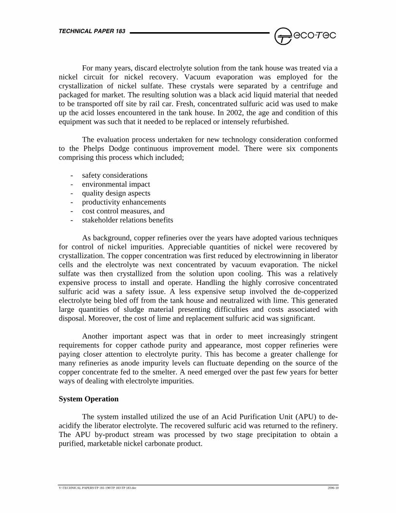
The system installed utilized the use of an Acid Purification Unit (APU) to de-acidify the liberator electrolyte. The recovered sulfuric acid was returned to the refinery. The APU by-product stream was processed by two stage precipitation to obtain a purified, marketable nickel carbonate product.
TECHNICAL PAPER 183
Y:\TECHNICAL PAPERS\TP 181-190\TP 183\TP 183.doc 2006-10
Figure 1 – Tankhouse Bleed Electrolyte Treatment System
The process, as depicted in Figure 1, shows electrolyte solution from the existing liberator cells delivered to the system. A backwashable media filter was used to remove suspended solids from solution. Filtered solution was then transferred to the APU feed tank. Feed solution was pumped through the APU where acid was sorbed by the ion exchange resin material while the metallic salt impurities passed through to the by-product. This by-product stream consisted of the metallic salts and a small amount of free sulfuric acid. Water used for ‘regeneration’ of the ion exchange resin was pumped down through the APU resin bed. The sulfuric acid was desorbed as a product solution. The purified solution exited from the APU and was collected for reuse within the tank house.
Typical process specifications around the APU subsystem are shown in Table 1. Up to 20,000 gallons per day of liberator solution was processed resulting in a nickel removal rate of up to 1,875 pounds per day.
Table 1 – APU System Performance
Stream H2SO4 (g/L)
Ni (g/L)
Cu (g/L)
Flow (USgal/day)
Feed 275 15.00 5.00 20,000 Acid Product 240 3.75 1.25 20,000 Metal By-product 35 11.25 3.75 20,000 Water - - - 20,000 Loss/Removal 12.75% 75% 75% -
TECHNICAL PAPER 183
Y:\TECHNICAL PAPERS\TP 181-190\TP 183\TP 183.doc 2006-10
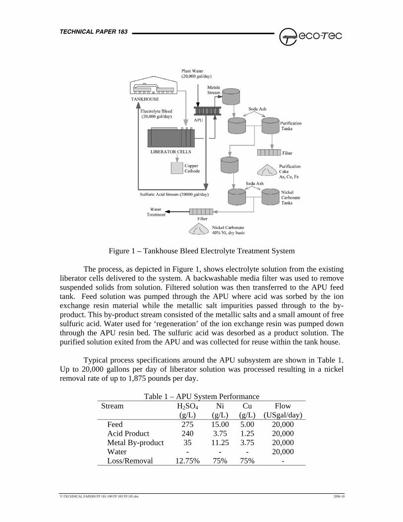
Typical performance indicated an acid recovery rate of greater than 87% and a nickel removal rate of greater than 75% through the APU system. Other metallic contaminants such as copper and iron were removed at the same efficiency. The majority of the arsenic followed the sulfuric acid back to the tank house (typically only 10 – 15% removal). Arsenic returning to the tank house was beneficial to cathode quality and current efficiency. Removal efficiency for contaminants such as antimony and bismuth were on the order of 50%. The APU system is shown in Figure 2 below.
Figure 2 – APU System at Phelps Dodge El Paso Refinery
The objective of the precipitation subsystem was to generate a pure nickel carbonate material. To that end, a two stage precipitation process was implemented. Soda ash was the neutralizing agent for both stages. The APU metal rich by-product solution was collected into one of two batch pH adjustment tanks for first stage processing. Soda ash from a bulk storage hopper was transferred to a vibratory feeder to a pH setpoint of 5.5. This forced the precipitation of contaminants such as arsenic, copper, iron, antimony, bismuth, and zinc. A second set of batch pH adjustment tanks were used for second stage processing. Soda ash was delivered in the same manner and to a pH set point of 11. This resulted in the precipitation of a clean nickel carbonate material. An assay of the first stage and second stage precipitate is shown in Table 2. All solids generated were dewatered in dedicated plate and frame filter presses.
Table 2 – Precipitate Assay (dry basis) Component First Stage Precipitate Second Stage Precipitate Nickel 5% 40% Arsenic 18% 0.07% Copper 10.3% - Iron 14.6% - Bismuth 0.06% - Antimony 0.18% - Zinc 0.4% - Moisture Content < 70% < 60%
TECHNICAL PAPER 183
Y:\TECHNICAL PAPERS\TP 181-190\TP 183\TP 183.doc 2006-10
First stage precipitate can typically be returned to the smelter operations. The second stage precipitate was sold for its nickel content. Perhaps the moisture content could be lowered with some fine tuning of the system; however, this was not deemed to be a major concern at that time. System commissioning has proven to be relatively straightforward with some minor operating adjustments undertaken with the precipitation subsystem. For example, some minor filtration considerations were encountered which were remedied by filter press cloth selection. System Benefits The system was commissioned in the summer of 2004 so there has now been over two years of operating experience taken place to assess the initial perceived benefits of the system. The benefits were organized into the Phelps Dodge continuous improvement model. Most benefits were a result of reduced operating costs over those of the previously installed vacuum evaporator system. Safety Safety considerations in the handling of the materials emanating from a system of this type are of utmost importance. An evaporator system necessitated the handling of black acid solution up to 1450 g/L of sulfuric acid. The present system ensured that operators now work with sulfuric acid no higher than 275 g/L. The fact that the APU product acid resembled actual electrolyte solution made it easier to recycle and handle rather than making up fresh electrolyte from a 93% H2SO4 concentration. Solution handling was performed at a lower temperature of 150 degrees F compared to well over 200 degrees F previously. The black acid solution previously had to be loaded onto rail cars and transported off site for disposal at a rate of five rail cars per month. Now, the lower sulfuric acid product is returned to the tank house for reuse. An important safety benefit credited to the system was that arsenic was returned along with the sulfuric acid for reuse. This dramatically reduced the need and associated safety ramifications of arsenic doping undertaken at the smelter as a means of controlling antimony/bismuth contaminants within the electrolyte solution. Environmental
The closed loop nature of the process contributed to addressing environmental considerations. The system has eliminated the amount of hazardous black acid. Water use has been reduced due to the recycle of the sulfuric acid back to the tank house. A number of benefits have also arisen pertaining to the operation of the on-site cogeneration plant. Previously, the liberator cells needed to operate such that low levels of copper (typically in the 250 ppm concentration range) in the electrolyte bleed solution was a requirement as a feed source to the evaporator system. Higher levels would make it difficult to centrifuge the nickel sulfate. The system can accept higher levels of copper from the
TECHNICAL PAPER 183
Y:\TECHNICAL PAPERS\TP 181-190\TP 183\TP 183.doc 2006-10
liberator cells. This resulted in a reduced amount of electrical usage demand for liberator cell operation resulting in fewer emissions from the cogeneration plant. The lower operating temperature of the system reduced steam use which, again, resulted in fewer emissions from the cogeneration plant. Lower iron and nickel concentrations in the electrolyte resulted in improved overall current efficiency further benefiting cogeneration plant operation. The handling of a low acid nickel product in super-sack containers was deemed an environmental benefit. Certainly, the minimizing of arsenic contamination in the nickel product also contributed to environmental benefits. Quality
Effective impurity removal improved cathode quality. Since over 80% of the arsenic was returned along with the sulfuric acid, the levels of antimony and bismuth in the electrolyte were lowered. Nodulation effects have been minimized as a result of the reduction of floating slimes caused by elevated antimony levels in the electrolyte. Bismuth deposition onto the cathode was also reduced. Effective removal of iron was also an important benefit in the control and optimization of current efficiency. Ensuring that the nickel carbonate material was low in impurities ensured acceptance by customers to utilize this product. Production Productivity improvements have been realized due to higher current efficiency gains realized as a result of lower iron, lower antimony, lower bismuth, and higher arsenic levels present in the tank house electrolyte. The system was sized to handle higher nickel feeds at the smelter and refinery. The system also enabled production of an increased revenue nickel carbonate product. Cost
The system resulted in significant savings when compared to the previous method of nickel sulfate production. A major contributor to these savings involved the energy use reduction arising from the reduced use of steam and the optimization of current efficiency within the tank house and liberator cell operation. Additional cost savings resulted in an improved revenue stream for the sale of nickel carbonate and the ability to bring in higher nickel feed for the smelter and refinery. Sulfuric acid purchases have been reduced from a high of thirty trucks per month to one truck per month. The entire project resulted in a less than one year payback. Stakeholder Relations Implementing a cleaner technology has proven to be the right thing to do for all stakeholders. The improved safety aligned with environmental advantages has proven to be of great value.
TECHNICAL PAPER 183
Y:\TECHNICAL PAPERS\TP 181-190\TP 183\TP 183.doc 2006-10
IX REMOVAL OF ARSENIC
In some cases selective As removal from copper refinery electrolytes is required. Various ion exchange materials have been evaluated. These tests have indicated that the valence of the As (III or V) is critical. For example, some of the resins tested are not capable of removing As(V) while others have such high selectivity for As(V) that regeneration is extremely difficult if not impossible. Only one of these materials is currently commercially available. This exchange material is a specialty chelating resin utilizing a porous polymer matrix to which amine based functional groups have been attached. To date bench scale ion exchange column tests have been conducted with a synthetic electrolyte.
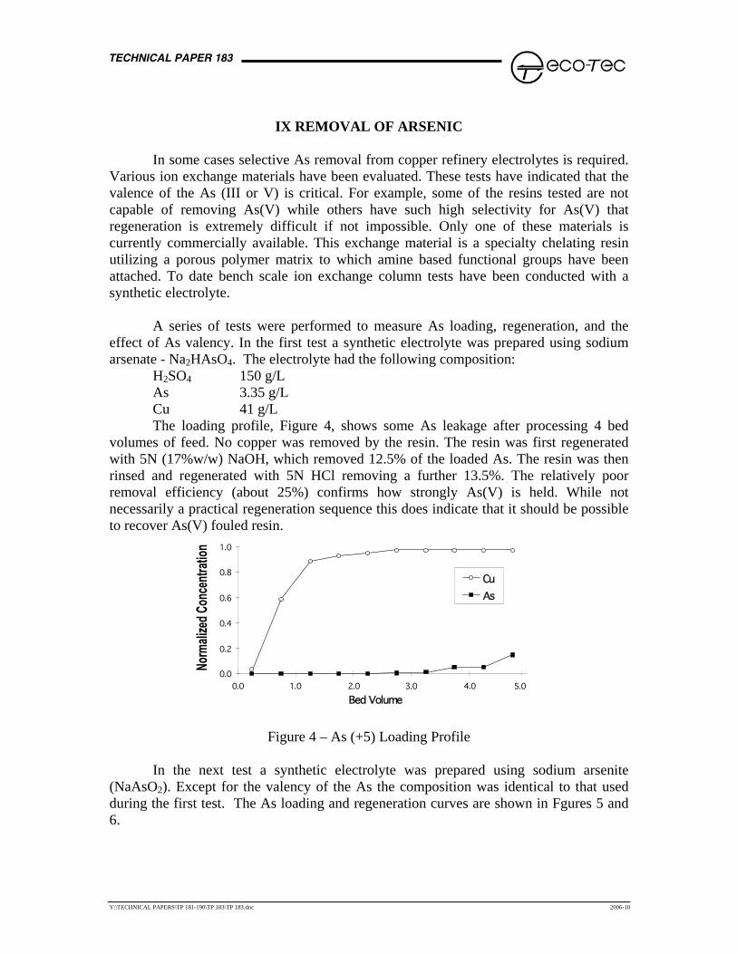
A series of tests were performed to measure As loading, regeneration, and the effect of As valency. In the first test a synthetic electrolyte was prepared using sodium arsenate - Na2HAsO4. The electrolyte had the following composition: H2SO4 150 g/L As 3.35 g/L Cu 41 g/L
The loading profile, Figure 4, shows some As leakage after processing 4 bed volumes of feed. No copper was removed by the resin. The resin was first regenerated with 5N (17%w/w) NaOH, which removed 12.5% of the loaded As. The resin was then rinsed and regenerated with 5N HCl removing a further 13.5%. The relatively poor removal efficiency (about 25%) confirms how strongly As(V) is held. While not necessarily a practical regeneration sequence this does indicate that it should be possible to recover As(V) fouled resin.
0.0
0.2
0.4
0.6
0.8
1.0
0.0 1.0 2.0 3.0 4.0 5.0 Bed Volume
CuAs
Figure 4 – As (+5) Loading Profile
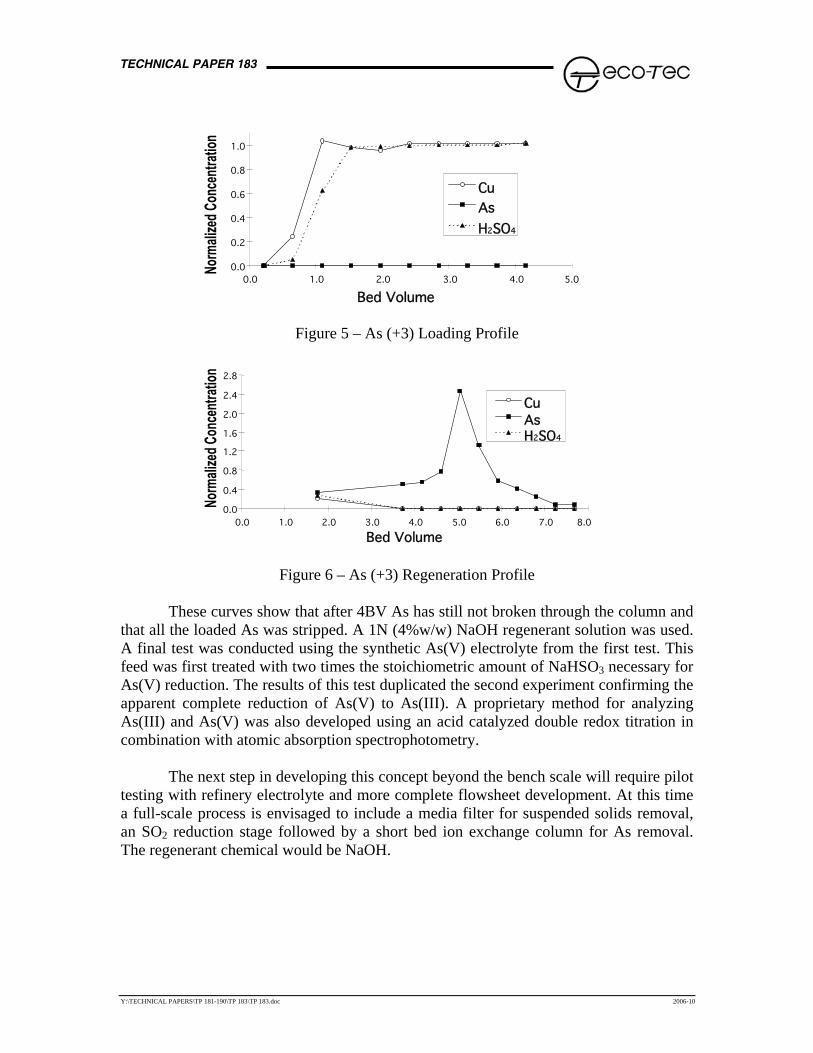
In the next test a synthetic electrolyte was prepared using sodium arsenite (NaAsO2). Except for the valency of the As the composition was identical to that used during the first test. The As loading and regeneration curves are shown in Fgures 5 and 6.
TECHNICAL PAPER 183
Y:\TECHNICAL PAPERS\TP 181-190\TP 183\TP 183.doc 2006-10
0.0
0.2
0.4
0.6
0.8
1.0
0.0 1.0 2.0 3.0 4.0 5.0 Bed Volume
CuAsH2SO4
Figure 5 – As (+3) Loading Profile
0.0 0.4 0.8 1.2 1.6 2.0 2.4 2.8
0.0 1.0 2.0 3.0 4.0 5.0 6.0 7.0 8.0 Bed Volume
CuAsH2SO4
Figure 6 – As (+3) Regeneration Profile
These curves show that after 4BV As has still not broken through the column and that all the loaded As was stripped. A 1N (4%w/w) NaOH regenerant solution was used. A final test was conducted using the synthetic As(V) electrolyte from the first test. This feed was first treated with two times the stoichiometric amount of NaHSO3 necessary for As(V) reduction. The results of this test duplicated the second experiment confirming the apparent complete reduction of As(V) to As(III). A proprietary method for analyzing As(III) and As(V) was also developed using an acid catalyzed double redox titration in combination with atomic absorption spectrophotometry.
The next step in developing this concept beyond the bench scale will require pilot testing with refinery electrolyte and more complete flowsheet development. At this time a full-scale process is envisaged to include a media filter for suspended solids removal, an SO2 reduction stage followed by a short bed ion exchange column for As removal. The regenerant chemical would be NaOH.
TECHNICAL PAPER 183
Y:\TECHNICAL PAPERS\TP 181-190\TP 183\TP 183.doc 2006-10
IX REMOVAL OF ANTIMONY/BISMUTH
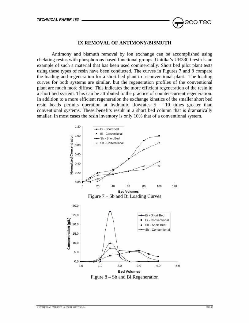
Antimony and bismuth removal by ion exchange can be accomplished using chelating resins with phosphorous based functional groups. Unitika’s UR3300 resin is an example of such a material that has been used commercially. Short bed pilot plant tests using these types of resin have been conducted. The curves in Figures 7 and 8 compare the loading and regeneration for a short bed plant to a conventional plant. The loading curves for both systems are similar, but the regeneration profiles of the conventional plant are much more diffuse. This indicates the more efficient regeneration of the resin in a short bed system. This can be attributed to the practice of counter-current regeneration. In addition to a more efficient regeneration the exchange kinetics of the smaller short bed resin beads permits operation at hydraulic flowrates 5 – 10 times greater than conventional systems. These benefits result in a short bed column that is dramatically smaller. In most cases the resin inventory is only 10% that of a conventional system.
0.00
0.20
0.40
0.60
0.80
1.00
1.20
0 20 40 60 80 100 120
Bed Volumes
Nor
mal
ized
Con
cent
ratio
n
Bi - Short BedBi - ConventionalSb - Short BedSb - Conventional
Figure 7 – Sb and Bi Loading Curves
0.0
5.0
10.0
15.0
20.0
25.0
30.0
0.0 1.0 2.0 3.0 4.0 5
Bed Volumes
Con
cent
ratio
n (g
/L)
.0
Bi - Short BedBi - ConventionalSb - Short BedSb - Conventional
Figure 8 – Sb and Bi Regeneration
TECHNICAL PAPER 183
Y:\TECHNICAL PAPERS\TP 181-190\TP 183\TP 183.doc 2006-10
These resins are very difficult to regeneration and typically require the use of concentrated hydrochloric acid. During these tests the resin was regenerated with 5N hydrochloric acid. Regeneration can also be accomplished using a mixture of NaCl and hydrochloric acid. In both cases a large regenerant excesses beyond the stoichiometric minimum is required. Typically some form of recovery system must be installed to recover the excess regenerant. For the hydrochloric acid regenerant this typically means an absorption evaporator tower. In the case of the NaCl/HCl regenerant this means a waste precipitation systems that will remove the metals but allow salt recycle.
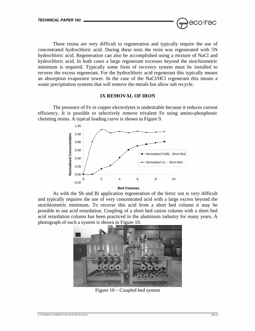
IX REMOVAL OF IRON
The presence of Fe in copper electrolytes is undesirable because it reduces current
efficiency. It is possible to selectively remove trivalent Fe using amino-phosphonic chelating resins. A typical loading curve is shown in Figure 9.
-0.20
0.00
0.20
0.40
0.60
0.80
1.00
1.20
0 2 4 6 8 10
Bed Volumes
Nor
mal
ized
Con
cent
ratio
n
Normalized Fe(III) - Short Bed
Normalized Cu - Short Bed
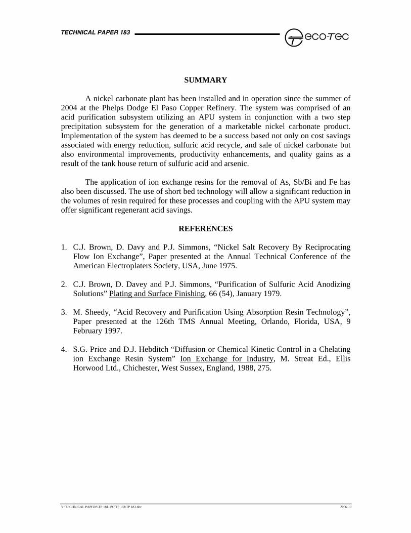
As with the Sb and Bi application regeneration of the ferric ion is very difficult
and typically requires the use of very concentrated acid with a large excess beyond the stoichiometric minimum. To recover this acid from a short bed column it may be possible to use acid retardation. Coupling of a short bed cation column with a short bed acid retardation column has been practiced in the aluminum industry for many years. A photograph of such a system is shown in Figure 10.
Figure 10 – Coupled bed system
TECHNICAL PAPER 183
Y:\TECHNICAL PAPERS\TP 181-190\TP 183\TP 183.doc 2006-10
SUMMARY
A nickel carbonate plant has been installed and in operation since the summer of
2004 at the Phelps Dodge El Paso Copper Refinery. The system was comprised of an acid purification subsystem utilizing an APU system in conjunction with a two step precipitation subsystem for the generation of a marketable nickel carbonate product. Implementation of the system has deemed to be a success based not only on cost savings associated with energy reduction, sulfuric acid recycle, and sale of nickel carbonate but also environmental improvements, productivity enhancements, and quality gains as a result of the tank house return of sulfuric acid and arsenic.
The application of ion exchange resins for the removal of As, Sb/Bi and Fe has
also been discussed. The use of short bed technology will allow a significant reduction in the volumes of resin required for these processes and coupling with the APU system may offer significant regenerant acid savings.
REFERENCES 1. C.J. Brown, D. Davy and P.J. Simmons, “Nickel Salt Recovery By Reciprocating
Flow Ion Exchange”, Paper presented at the Annual Technical Conference of the American Electroplaters Society, USA, June 1975.
2. C.J. Brown, D. Davey and P.J. Simmons, “Purification of Sulfuric Acid Anodizing
Solutions” Plating and Surface Finishing, 66 (54), January 1979. 3. M. Sheedy, “Acid Recovery and Purification Using Absorption Resin Technology”,
Paper presented at the 126th TMS Annual Meeting, Orlando, Florida, USA, 9 February 1997.
4. S.G. Price and D.J. Hebditch “Diffusion or Chemical Kinetic Control in a Chelating
ion Exchange Resin System” Ion Exchange for Industry, M. Streat Ed., Ellis Horwood Ltd., Chichester, West Sussex, England, 1988, 275.