Embed Size (px)
Citation preview

Technical Note - TN 007: 2018
Technical Note – TN 007: 2018
Subject: Update to EP 19 00 00 02 SP, version 4.1 to include harmonic filter protection requirements
Issued date: 11 April 2018
Effective date: 11 April 2018
For queries regarding this document [email protected]
www.asa.transport.nsw.gov.au
This technical note is issued by the Asset Standards Authority (ASA) to notify an update to
EP 19 00 00 02 SP Protection System Requirements for the High Voltage Network, version 4.1
by incorporating the standard protection requirements for a harmonic filter system.
1. Introduction Distribution network service providers have recently imposed stringent permissible harmonic
levels on the RailCorp high voltage network at the substation connection points and as a result,
there is a requirement to minimise the harmonics that is generated by the 12-pulse rectifiers in
the dc traction substations.
The harmonic filters will be used to reduce the levels of harmonics generated by the 12-pulse
rectifier in the traction substation, thereby improving the power quality of the RailCorp high
voltage network.
This technical note defines the standard protection requirements for a C-type passive harmonic
filter to be designed by an AEO for the RailCorp 11 kV and 33 kV high voltage network.
The harmonic filter protection requirements apply to all 11 kV or 33 kV RailCorp substations that
require a harmonic filter to be installed.
2. Primary protection The primary protection for the harmonic filter shall be provided by an overcurrent and earth fault
protection relay and two specialised harmonic filter protection relays for the protection of the
reactor and capacitor banks.
The auxiliary capacitor is not protected; instead it shall be rated conservatively to ensure that it
does not fail under any reasonable operating conditions.
© State of NSW through Transport for NSW 2017 Page 1 of 11

Technical Note - TN 007: 2018
Similarly, the damping resistor is not supplied with overcurrent protection as it shall be very
conservatively rated.
2.1. Overcurrent and earth fault protection The capacitor banks shall be protected by an overcurrent and earth fault protection relay to detect
filter bank internal short circuits and earth fault currents.
2.2. Phase undervoltage protection Phase undervoltage protection shall also be provided by the overcurrent and earth fault relay to
trip the harmonic filter ACCB and start a timer relay to inhibit re-energisation of the harmonic filter
before the capacitors are discharged to a safe voltage.
2.3. Repetitive peak overvoltage protection Repetitive peak overvoltage protection shall be provided by a specialised harmonic filter
protection relay for the capacitor banks and shall withstand an RMS sinusoidal voltage of 110%
rated voltage at rated frequency for extended periods, or higher voltages for shorter period as
described by the temporary overvoltage withstand curves in the relevant ANSI and IEC
recommendations.
2.4. Thermal overcurrent protection Thermal overcurrent protection shall be provided by a specialised harmonic filter protection relay
to protect the harmonic filter components from excessive temperature rise as limited by
adjustable threshold settings on the relay.
2.5. Unbalance protection Protection of the capacitor banks is achieved mainly by means of unbalance protection. The
unbalance protection shall be provided by two specialised harmonic filter protection relays to
protect the capacitor banks that are connected in a double star point and H-bridge configurations.
The unbalance protection shall be required to raise an alarm in the event of a failure of one or
more capacitor elements and to trip the circuit breaker in the event of a failure of two or more
elements. The protection shall not be able to permit overvoltage stressing of capacitor units.
2.5.1 Double star point unbalance protection Double star point unbalance protection shall be provided by a specialised harmonic filter
protection relay to monitor the flow of current between the double star points of the harmonic filter
capacitor banks in the event of component failure.
The time delay settings of the unbalance relays are usually 1 s for alarm and 0.1 s for tripping.
© State of NSW through Transport for NSW 2017 Page 2 of 11

Technical Note - TN 007: 2018
The time delay for trip shall be the shortest possible to avoid serious damage in case of element
breakdown.
2.5.2 H-bridge unbalance protection H-bridge unbalance protection shall be provided by a separate specialised harmonic filter
protection relay for each phase of the capacitor bank.
3. Backup protection Backup protection shall be provided by an upstream overcurrent and earth fault protection relay.
4. Breaker fail scheme The failure of the circuit breaker to open in response to a protection trip command shall be
detected and the associated bus-zone MTM relay shall be energised. A time delay of 0.2 seconds
shall be provided to avoid nuisance tripping.
The protection relays should provide this function.
5. Trip circuit supervision Trip circuit supervision shall be implemented either as a function of the protection relay or
installation of a dedicated TCS relay.
6. Location of current transformers The preferred locations of the protection current transformers (CTs) are as follows:
• overcurrent and earth fault – feeder side of the ACCB
• thermal overcurrent – feeder side of the ACCB
• repetitive peak overvoltage (shared the same CT as thermal overcurrent) – feeder side of the
ACCB
The preferred locations of the unbalance protection CTs in the capacitor banks are as follows:
• H-bridge unbalance – reference A phase CT on feeder side of ACCB (CTs on the H-bridge)
• Double star unbalance – reference A, B and C phase CTs on feeder side of ACCB (CTs on
the star point)
7. Voltage transformer A voltage transformer shall be provided for all three phases and can either be a three-phase
voltage transformer or three single-phase voltage transformers.
Voltage transformers shall be connected to an overcurrent and earth fault protection relay to
provide phase undervoltage protection.
© State of NSW through Transport for NSW 2017 Page 3 of 11

Technical Note - TN 007: 2018
The voltage transformers shall have an accuracy class 3P and rated burden 45 VA or 50 VA. A
dedicated voltage transformer may not be required and where available, inputs from the existing
bus section voltage transformer may be used.
8. Metering requirements The harmonic filter shall be provided with a current transformer, a current transducer and an
ammeter for local and remote metering only on B-phase.
9. SCADA All alarms from the protection relays shall be sent to SCADA via Serial DNP3.0 or Modbus where
available, with a strong preference for DNP3.0. Typically, alarms from the overcurrent and earth
fault relay are sent to the RTU via the serial link. Alarms from the harmonic filter relay shall be
hardwired to the RTU. Details of SCADA alarms are included in Appendix E.
10. Interlock To prevent personnel from accessing the harmonic filter prior to the capacitors being discharged
to less than 50 V ac, a timer circuit and key lock switch arrangement shall be employed. The
timer circuit is also used to inhibit re-closure of the harmonic filter ACCB after an open/trip
operation.
The timer setting shall be based on the time constant of the filter RLC plus an appropriate safety
margin to allow the capacitors to discharge to less than 50 V ac.
If the mechanical key lock is not available, then electro-mechanical interlocking shall be employed
between electro-mechanical key lock release and a timer relay.
Additional safety requirements may be required to ensure the capacitor banks are discharged to
less than 50 V ac before releasing the locks.
The interlock shall be implemented on the harmonic filter switchgear panel and shall not rely on
the SCADA system to inhibit control of the harmonic filter ACCB during capacitor discharge.
© State of NSW through Transport for NSW 2017 Page 4 of 11

Technical Note - TN 007: 2018
Appendix A Protection relays and ACCB trip coils Table 1 details the protection schemes for harmonic filter, type approved protection relays and
ACCB trip coils for use in the RailCorp HV electrical network when a new harmonic filter is
installed.
Table 1 – Harmonic filter protection scheme, relay and trip coil
Protection scheme Relay Trip coil
Overcurrent and earth fault MiCOM P127 1
Phase undervoltage MiCOM P127 1
Repetitive peak overvoltage RLC04 Relay 1 2
Thermal overcurrent RLC04 Relay 1 2
Double star point unbalance RLC04 Relay 1 2
H-bridge unbalance RLC04 Relay 2 2
Appendix B Protection relay identification Table 2 details the protection scheme and relays identification and abbreviations for harmonic
filter protection.
Table 2 - Harmonic filter protection scheme and relays identification
Relay identifier Protection scheme description Abbreviation
51/HF Overcurrent and earth fault protection OC & EF
27/HF Phase undervoltage protection PUV
59/HF Repetitive peak overvoltage protection POV
49/HF Thermal overcurrent protection TOV
60/HF Double star point unbalance protection DSUB
60/HF H-bridge unbalance protection HUB
Appendix C Current transformers Table 3 and Table 4 provide details of typical protection and metering CTs that are compliant with
AS 60044.1 Instrument transformers Part 1: Current transformers with a rated secondary current
of 1A and minimum rated continuous thermal current of at least 150% of rated primary current.
Table 3 – Typical harmonic filter protection CTs (switchboardpanel)
Protection current transformers CT designation Typical CT ratio
Standard accuracy class for overcurrent and earth fault CTs
Class 10P20 300/150/1
Standard accuracy class for unbalance protection CT
Class 10P20 300/150/1
© State of NSW through Transport for NSW 2017 Page 5 of 11

Technical Note - TN 007: 2018
Table 4- Typical harmonic filter metering CTs
Metering current transformers CT designation Typical CT ratio
Standard accuracy class for metering CTs
Class 1 300/1
Appendix D Standard test block wiring and input/output relay configuration
HARMONIC FILTER PROTECTION: DOUBLE-STAR POINT UNBALANCE PROTECTION,
REPETITIVE PEAK OVERVOLTAGE, THERMAL OVERCURRENT
RLC04 RELAY 1
Relay 1 MMLG01 Incoming Supplies
Trip contact (Term. 10) 2 x 1 Trip +ve
Trip contact (Term. 12) 4 x 3 RPOV, TOC & DSUB Trip
SPARE 6 x 5 SPARE
SPARE 8 x 7 SPARE
CT input (Term. 28) 10 x 9 Icap (double star unbalance CT)
CT input (Term. 27) 12 x 11 Icap (double star unbalance CT)
Aux input (Term. 5) 14 II 13 + 125 V dc aux supply
Aux input (Term. 7) 16 x 15 - 125 V dc aux supply
CBFail trip contact (Term. 17) 18 x 17 Trip +ve
CBFail trip contact (Term. 19) 20 x 19 CBFail trip
CT input 1 (Term. 22) 22 x 21 TBK 2 (Term. 11)
CT input 2 (Term 24) 24 x 23 Ib (Line CT)
CT input 3 (Term 26) 26 x 25 Ic (Line CT)
CT inputs 4 (Term. 21,23, 25) 28 x 27 Io (Line CT)
OUTPUT RELAYS:
RELAY K1 REPETITIVE PEAK OVERVOLTAGE, THERMAL OVERCURRENT & DOUBLE
STAR UNBALANCE TRIP
RELAY K2 DOUBLE STAR POINT UNBALANCE ALARM
RELAY K3 REPETITIVE PEAK OVERVOLTAGE AND THERMAL OVERCURRENT ALARM
RELAY K4 BREAKER FAIL ALARM
RELAY K5 BREAKER FAIL TRIP
RELAY K6 RLC04 RELAY 1 FAIL ALARM
INPUT RELAYS:
INPUT 1 SPARE
© State of NSW through Transport for NSW 2017 Page 6 of 11
Technical Note - TN 007: 2018
HARMONIC FILTER PROTECTION: H-BRIDGE UNBALANCE PROTECTION
RLC04 RELAY 2
Relay 2 MMLG01 Incoming Supplies
Trip contact (Term. 10) 2 x 1 Trip +ve
Trip contact (Term. 12) 4 x 3 H-Bridge unbalance trip
CT input (Term. 23) 6 x 5 Ia- (H-Bridge A phase CT)
CT input (Term. 25) 8 x 7 Ib- (H-Bridge B phase CT)
CT input (Term. 27) 10 x 9 Ic- (H-Bridge C phase CT)
CT input (Term. 21) 12 x 11 TBK 1 (Term. 21)
Aux input (Term. 5) 14 II 13 + 125 V dc aux supply
Aux input (Term. 7) 16 x 15 - 125 V dc aux supply
CBFail contact (Term. 17) 18 x 17 Trip +ve
CBFail contact (Term. 19) 20 x 19 CBFail timer initiate to P127 (27/51/HF) relay
CT input 1 (Term. 24) 22 x 21 Ia+ (H-Bridge A phase CT)
CT input 2 (Term. 26) 24 x 23 Ib+ (H-Bridge B phase CT)
CT input 3 (Term. 28) 26 x 25 Ic+ (H-Bridge C phase CT)
CT input 4 (Term. 22) 28 x 27 Ia+ (11 kV A phase line CT)
OUTPUT RELAYS:
RELAY K1 H-BRIDGE UNBALANCE TRIP
RELAY K2 H-BRIDGE UNBALANCE ALARM
RELAY K3 SPARE
RELAY K4 SPARE
RELAY K5 TRIP – BREAKER FAIL TIMER INITIATE TO P127 (27/51/HF) RELAY, INPUT L5
RELAY K6 RLC04 RELAY 2 FAIL ALARM
INPUT RELAYS:
INPUT 1 SPARE
© State of NSW through Transport for NSW 2017 Page 7 of 11

Technical Note - TN 007: 2018
HARMONIC FILTER PROTECTION: OVERCURRENT & EARTH FAULT PROTECTION AND
UNDERVOLTAGE PROTECTION
P127 RELAY
Relay MMLG01 Incoming Supplies
RELAY 1 contact 2 x 1 Trip +ve
RELAY 1 contact 4 x 3 Overcurrent and earth fault and phase undervoltage trip
VT input 1 (Term. 69) 6 x 5 Va
VT input 2 (Term. 71) 8 x 7 Vb
VT input 3 (Term. 73) 10 x 9 Vc
VT input 4 (Term. 70, 72, 74) 12 x 11 Vo
TERMINAL 33 14 II 13 + 125 V dc aux supply
TERMINAL 34 16 x 15 - 125 V dc aux supply
RELAY 8 contact 18 x 17 Trip +ve
RELAY 8 contact 20 x 19 Breaker fail trip
Ia 22 x 21 Ia
Ib 24 x 23 Ib
Ic 26 x 25 Ic
Io 28 x 27 Io
OUTPUT RELAYS:
RELAY 1 OVERCURRENT & EARTH FAULT AND PHASE UNDERVOLTAGE TRIP
RELAY 2 SPARE
RELAY 3 SPARE
RELAY 4 SPARE
RELAY 5 SPARE
RELAY 6 SPARE
RELAY 7 SPARE
RELAY 8 BREAKER FAIL TRIP
Note: All alarms except the watchdog are to be serial linked (DNP3.0)
INPUT RELAYS:
INPUT L1 SPARE
INPUT L2 SPARE
INPUT L3 SPARE
INPUT L4 TCS
INPUT L5 Timer initiate from RLC04[2]
INPUT L6 SPARE
INPUT L7 SPARE
© State of NSW through Transport for NSW 2017 Page 8 of 11

Technical Note - TN 007: 2018
Appendix E Protection SCADA alarms Details of SCADA alarms are listed below.
Overcurrent and earth fault protection relay P127
• OC trip alarm (OVERCURRENT A, OVERCURRENT B, OVERCURRENT C)
• EF trip alarm
• phase undervoltage trip alarm
• breaker fail alarm
• TCS alarm (Trip coil 1 via P127)
• relay watchdog alarm
Harmonic filter protection relay 1 RLC04 [1]
• repetitive peak overvoltage and thermal overcurrent alarm
• double star point unbalance alarm
• breaker fail alarm
• relay watchdog alarm
Harmonic filter protection relay 2 RLC04 [2]
• H-bridge unbalance alarm
• breaker fail alarm
• relay watchdog alarm
© State of NSW through Transport for NSW 2017 Page 9 of 11

Technical Note - TN 007: 2018
Appendix F General connection drawing Figure 1 represents the harmonic filter protection general connection drawing.
Figure 1 – Harmonic filter protection general connection drawing
© State of NSW through Transport for NSW 2017 Page 10 of 11

Technical Note - TN 007: 2018
Authorisation:
Technical content prepared by
Checked and approved by
Interdisciplinary coordination checked by
Authorised for release
Signature
Date
Name Rahul Chowdhury Matthew Percival Jason R. Gordon Jagath Peiris
Position Technical Specialist Electrical Network
A/Lead Electrical Engineer
Chief Engineer Director Network Standards and Services
© State of NSW through Transport for NSW 2017 Page 11 of 11

Technical Note - TN 039: 2015
© State of NSW through Transport for NSW Page 1 of 3
Technical Note - TN 039: 2015
Subject: RailCorp Electrical Network – High Voltage Feeders – P ilot Wire Schematic Drawings
Issued date: 30 June 2015
Effective date: 30 June 2015
For queries regarding this document [email protected]
www.asa.transport.nsw.gov.au
1. Introduction The majority of high voltage feeders on the RailCorp electrical network have a pilot wire
protection scheme installed.
Where there is a pilot wire scheme installed, then in addition to the schematic diagrams produced
for the individual equipment at either end of the scheme, an overall "Pilot Wire Schematic"
drawing is required to be produced.
2. Modifications to existing pilot wire schemes When an existing pilot wire scheme is being modified then the associated schematics and the
pilot wire schematic drawing must be modified.
If an existing pilot wire scheme is being modified and there is not an existing pilot wire schematic
drawing, then the project is responsible for producing a pilot wire schematic drawing.
Where an additional substation is installed between two existing substations and hence the
existing pilot wire scheme becomes two schemes there shall be a pilot wire schematic for each
individual scheme. The project is responsible for producing the pilot wire schematics.
3. Content and layout of pilot wire scheme drawing The content of the pilot wire schematic diagram shall typically include the following for both ends
of the scheme:
• High voltage busbars, associated ACCB's, ABSW's and links

Technical Note - TN 039: 2015
© State of NSW through Transport for NSW Page 2 of 3
• Current transformers (including CT's used for other protection schemes) with secondary
circuitry connection to the pilot wire relay. CT's to be shown in correct position and
polarity identified.
• Voltage transformers
• Pilot wire relays and associated test blocks, with all connections to the PW relay detailed
and referenced to the equipment schematic drawings.
• Auxiliary supply to the PW relay and SCADA alarms
• Schematic representation of the communication scheme between PW relays
• Relevant notes and an Item list
The following drawings provide examples of the typical content and layout to be included on the
diagram:
• RailCorp drawing: EL0518527, Cardiff to Hamilton, 750 Feeder
• RailCorp drawing: EL0498117, Edgecliff to Prince Alfred, 755 Feeder
• RailCorp drawing EL0273924, Berowra to Cowan, 830 Feeder
4. Title block content All drawings are required to comply with the RailCorp CAD manual. Specifically the content of the
title block for pilot wire scheme drawing is detailed in Table 1 below:
Table 1 – Title block content
Line Description
LINE 1 Location X to Location Y (eg: PRINCE ALFRED TO ARGYLE)
LINE 2 Rail Corridor (eg: NORTH SHORE LINE)
LINE 3 SUBSTATIONS, XXkV FEEDER YYY (eg: SUBSTATIONS, 33 kV FEEDER 746)
LINE 4 PILOT WIRE PROTECTION
LINE 5 SCHEMATIC DIAGRAM

Technical Note - TN 039: 2015
© State of NSW through Transport for NSW Page 3 of 3
Authorisation:
Technical content prepared by
Checked and approved by
Interdisciplinary coordination checked by
Authorised for release
Signature
Name Chris Lilly Neal Hook John Paff Graham Bradshaw
Position Principal Engineer Substations and HV Network
Lead Electrical Engineer
A/Chief Engineer Principal Manager Network Standards & Services

PROTECTION SYSTEM REQUIREMENTS FOR THE HIGH
VOLTAGE NETWORK
EP 19 00 00 02 SP
Engineering Standard Electrical
Version 4.1
Issued June 2012
Owner: Chief Engineer Electrical
Approved by:
Neal Hook Chief Engineer Electrical
Authorised by:
Neal Hook Chief Engineer Electrical
Disclaimer This document was prepared for use on the RailCorp Network only. RailCorp makes no warranties, express or implied, that compliance with the contents of this document shall be sufficient to ensure safe systems or work or operation. It is the document user’s sole responsibility to ensure that thecopy of the document it is viewing is the current version of the document as in use by RailCorp. RailCorp accepts no liability whatsoever in relation to the use of this document by any party, and RailCorp excludes any liability which arises in any manner by the use of this document. Copyright The information in this document is protected by Copyright and no part of this document may be reproduced, altered,stored or transmitted by any person without the prior consent of RailCorp.
Engi
neer
ing
Stan
dard
UNCONTROLLED WHEN PRINTED Page 1 of 71

RailCorp Engineering Standard — Electrical Protection System Requirements for the High Voltage Network EP 19 00 00 02 SP
Document control
Version Date Summary of change June 2007 Last Technical Review
4.0 May 2010 Application of TMA 400 format 4.1 June 2012
• Update list of Australian and RailCorp standards • Incorporate P543 & P124 standard test block
diagrams, input and output relay configuration • Incorporate a section on Rectifier transformer frame
leakage • Update Approved Protection Relay and incorporate
standard test block diagrams. • Update headings & numbering of section 6.2 • Voltage transducer model changed to ISTAT 400
series. • Update Voltage transformer burdens • Incorporate a section for Voltage transformer for
11kV side of system transformers. • Update the metering requirements for 66, 33 &
11kV feeders • Added new appendix detailing metering
requirements for bulk supply locations. • Added new appendix detailing wire codes for CT’s,
VT’s and related equipment. • Incorporate 11kV overcurrent protection on system
transformers in ACCB Trip Coil table . • Incorporate a section for the Requirement for
capacity of batteries added. • Incorporate standard test block diagram for neutral
leakage protection. • Update Approved protection relays for new
switchboards.
© RailCorp Page 2 of 71 Issued June 2012 UNCONTROLLED WHEN PRINTED Version 4.1

© RailCorp Page 3 of 71 Issued June 2012 UNCONTROLLED WHEN PRINTED Version 4.1
RailCorp Engineering Standard — Electrical Protection System Requirements for the High Voltage Network EP 19 00 00 02 SP
Contents
1 Introduction .............................................................................................................................6
2 Normative References ............................................................................................................6
2.1 International Standards..............................................................................................6
2.2 Australian Standards .................................................................................................6
2.3 RailCorp Documents..................................................................................................7
2.4 RailCorp Drawings.....................................................................................................7
2.5 Industry Publications..................................................................................................7
3 Definitions and Abbreviations ...............................................................................................7
4 General Protection Philosophy .............................................................................................8
4.1 General ......................................................................................................................8
4.2 Protection Settings.....................................................................................................9
4.3 Grading ......................................................................................................................9
5 Specific Protection Equipment Requirements.....................................................................9
5.1 Protection Equipment Design Principles - All New HV Switchgear...........................9
5.2 Interfacing New Protection Schemes With Existing Equipment ..............................10
5.2.1 Multiple Use of Current Transformers ......................................................10
5.2.2 Trip Circuit Supervision ............................................................................10
5.2.3 Breaker Fail ..............................................................................................10
5.2.4 Inter-trip ....................................................................................................10
5.3 Current Transformers (CT) ......................................................................................10
5.3.1 General Requirements .............................................................................10
5.3.2 Multiple Ratio Current Transformers ........................................................11
5.3.3 Protection Current Transformers..............................................................11
5.3.4 Measurement Current Transformers........................................................11
5.3.5 Current Transformer Secondary Wiring ...................................................12
5.4 Voltage Transformers ..............................................................................................12
5.4.1 General Requirements .............................................................................12
5.4.2 Voltage Transformer Secondary Wiring ...................................................13
5.4.3 Voltage Transformer Alarms ....................................................................13
5.4.4 Voltage Transformer Supply to Protection Relays ...................................13
5.4.5 Voltage Transformer for 11kV Side of System Transformers ..................13
5.5 Auxiliary Supply (DC)...............................................................................................13
5.5.1 General Requirements .............................................................................13
5.5.2 Requirement for Two battery Systems.....................................................14
5.6 Protection Relays.....................................................................................................14
5.7 Close Inhibit .............................................................................................................15
5.8 Protection Alarms ....................................................................................................15
5.9 Inter-Trip Arrangements...........................................................................................15
5.9.1 Preferred Technology...............................................................................15
5.9.2 Fibre Optic Pilots ......................................................................................15
5.9.3 Copper Pilots............................................................................................15
5.10 Integrated Support System......................................................................................16

e 4 of 71 rsion 4.1
ge
© RailCorp PaIssued June 2012 UNCONTROLLED WHEN PRINTED V
RailCorp Engineering Standard — Electrical Protection System Requirements for the High Voltage Network EP 19 00 00 02 SP
6 Specific Equipment Applications ........................................................................................16
6.1 33kV & 66kV Feeders..............................................................................................16
6.1.1 Standard Protection Schemes .................................................................16
6.1.2 Primary Protection....................................................................................16
6.1.3 Backup protection.....................................................................................16
6.1.4 Circuit Breaker Fail Scheme ....................................................................17
6.1.5 Location of Current Transformers ............................................................17
6.1.6 Metering Requirements............................................................................17
6.2 11kV feeders............................................................................................................18
6.2.1 Standard Protection Schemes .................................................................18
6.2.2 Primary Protection....................................................................................18
6.2.3 Backup protection.....................................................................................18
6.2.4 Circuit Breaker Fail Scheme ....................................................................19
6.2.5 Location of Current Transformers ............................................................19
6.2.6 Metering Requirements............................................................................19
6.3 High Voltage Busbars & Bus-Tie Cables.................................................................19
6.3.1 Primary Protection for Busbars ................................................................19
6.3.2 Primary Protection for Bus-tie Cables ......................................................20
6.3.3 Backup Protection ....................................................................................20
6.3.4 Location of Current Transformers ............................................................20
6.4 Rectifier Transformer and Power Cubicle................................................................20
6.4.1 Primary Protection....................................................................................20
6.4.2 Backup Protection ....................................................................................21
6.4.3 Rectifier Transformer Frame leakage ......................................................21
6.4.4 Circuit Breaker Fail Scheme ....................................................................21
6.4.5 Protection Interface Requirements...........................................................21
6.5 System Transformers ..............................................................................................21
6.5.1 Standard Protection Schemes .................................................................21
6.5.2 Primary Protection....................................................................................21
6.5.3 Backup Protection ....................................................................................22
6.5.4 Circuit Breaker Fail Scheme ....................................................................22
6.5.5 Neutral Leakage .......................................................................................22
6.5.6 Buchholz Relay ........................................................................................22
6.5.7 Location of Current Transformers ............................................................22
6.6 11kV/415V Transformers.........................................................................................23
6.6.1 Transformers Supplied from Ring Main Units ..........................................23
6.6.2 Transformers Supplied from SCADA Controlled ACCB’s ........................23
6.6.2.1 Standard Protection Schemes ..................................................23
6.6.3 Primary Protection....................................................................................23
6.6.4 Backup Protection ....................................................................................23
6.6.5 Circuit Breaker Fail Scheme ....................................................................23
6.7 Documentation Requirements .................................................................................23
6.7.1 System Definition Review (SDR) Documentation ....................................24
6.7.2 Preliminary (PDR) & Critical Design Review (CDR) Documentation .........................................................................................24
6.7.3 System Verification Review (SVR) Documentation .................................24

© RailCorp Page 5 of 71 Issued June 2012 UNCONTROLLED WHEN PRINTED Version 4.1
RailCorp Engineering Standard — Electrical Protection System Requirements for the High Voltage Network EP 19 00 00 02 SP
Appendix A Protection Relays ..................................................................................................25
Appendix B ACCB Trip Coils - Standard Equipment Connection .........................................27
Appendix C Two Battery Systems (125V DC) - Standard Protection Equipment Connection .............................................................................................................28
Appendix D Interfacing With Existing Pilot Wire Schemes....................................................29
Appendix E Current Transformers (33kV & 66kV)...................................................................30
Appendix F Current Transformers for 11kV Switchgear........................................................32
Appendix G Protection Relay Identification.............................................................................33
Appendix H Standard Test Block Wiring & Input/Output Relay Configuration....................34
Appendix I Voltage and Current Transducers........................................................................54
Appendix J Pilot Wire Schemes ...............................................................................................55
Appendix K Auto Re-close on High Voltage Feeders .............................................................56
Appendix L Protection SCADA Alarms....................................................................................57
Appendix M Implementation Of SCADA Alarms & Control ....................................................59
Appendix N Typical ACCB Auxiliary Supply Arrangement ....................................................60
Appendix O Protection Relay Labelling Guidelines................................................................62
Appendix P Standard Current Transformer Configurations ..................................................65
Appendix Q Metering Requirements For Bulk Supply Points................................................68
Appendix R Current Transformer, Voltage Transformer and General Protection - Wire Identification Code ..................................................................70
Appendix S Protection Non-Compliances Particular to the ECRL Project...........................71
RailCorp Engineering Standard — Electrical Protection System Requirements for the High Voltage Network EP 19 00 00 02 SP
1 Introduction This document covers the Protection System requirements for the RailCorp High Voltage AC Network for 11kV, 33kV, 66kV and 132kV system voltages.
This document does not include protection requirements for the 1500V DC system.
The Specific Protection Equipment Requirements (Section 5 and associated Appendix) are common requirements for the entire high voltage network.
These protection requirements cover general design principles for protection schemes, as well as requirements relating specifically to the protection equipment. They do not include equipment used for detection and measurement of non-electrical protection parameters (such as oil and gas sudden pressure change, fibre optic temperature measurement), other than to specify necessary interface details.
The correct design, implementation and management of the overall protection system are critical to the safe and reliable operation of the RailCorp power system. As such, all design processes for the protection system must follow the RailCorp Engineering Design Management Procedures.
All new installations, modified and refurbished existing installations must comply with the requirements in this document.
High voltage protection systems existing at the date of release of this document are not affected by the requirements of this document.
2 Normative References The following documents are either referenced in this standard or can provide further information. The edition is current at the time of publication of this document.
2.1 International Standards IEEE C.37.2 - 2008 Standard electrical power system device function numbers and contact designations.
2.2 Australian Standards AS 1243: 1982 Voltage Transformers for Measurement and Protection AS 1675: 1986 Current Transformers – Measurement and Protection AS 2067: 2008 Switchgear assemblies and ancillary equipment for alternating
voltages above 1 kV AS 60044.1: 2007 Instrument Transformers – part 1: Current Transformers AS 60044.2: 2007 Instrument Transformers – part 2: Single Phase Inductive
Voltage Transformers
© RailCorp Page 6 of 71 Issued June 2012 UNCONTROLLED WHEN PRINTED Version 4.1

RailCorp Engineering Standard — Electrical Protection System Requirements for the High Voltage Network EP 19 00 00 02 SP
2.3 RailCorp Documents EP 00 00 00 01 TI RAC Electrical system General Description EP 06 00 00 01 SP System Substation Battery EP 00 00 00 12 SP Electrical Power Equipment – Integrated Support Requirements EP 00 00 00 13 SP Electrical Power Equipment – Design Ranges of Ambient
Conditions EP 00 00 00 15 SP Common requirements for Electrical Power Equipment EP 00 00 00 00 MP Electric Power Technical Maintenance Plan EP 03 02 00 01 SP Controls and Protection for Rectification Equipment EP 99 00 00 02 SP System Commissioning tests EP 01 00 00 01 SP 33kV AC Indoor Switchgear – Non-Withdrawable EP 01 00 00 04 SP 33kV Outdoor Live Tank Circuit Breaker and Post Type CT’s EP 01 00 00 05 SP 33kV Outdoor Dead Tank Circuit Breaker Assembly EP11 00 00 07 SP Design Technical Reviews for Electrical SCADA Equipment
2.4 RailCorp Drawings EL 0283030 33KV Transformer Frame Leakage Arrangement
2.5 Industry Publications Network Protection & Automation Guide (Alstom) (previously titled: Protective Relays Application Guide) Schneider/Alstom/Areva Protection Relay Application Guides
3 Definitions and Abbreviations ACCB Alternating current circuit breaker
DC Auxiliary Supply Supply for the operation of electronic protection relays, energisation of multi-trip relay coils, energisation of HV ACCB trip and close coils and general control circuit operations. Nominally 125V DC or 48V DC.
CT(s) Current Transformer(s)
DC Direct Current
Dedicated Pilot Cable A communication cable that is used only for the control, indication and pilot wire functions between two substations. The cable is continuous between substations.
FAT Factory acceptance test
ILIS Acronym for Intelligent Light Information System which is a RailCorp approved busbar fault detection scheme in use on Areva/Schneider WSA GIS switchgear.
IT Inter-trip
Low Voltage Compartment The compartment on the high voltage switchgear where the protection relays, control equipment and wiring is installed. The compartment is usually accessed by a hinged door and does not require any isolation or operation of the switchgear for safe access.
© RailCorp Page 7 of 71 Issued June 2012 UNCONTROLLED WHEN PRINTED Version 4.1

RailCorp Engineering Standard — Electrical Protection System Requirements for the High Voltage Network EP 19 00 00 02 SP
MTA Protection relay used for the multi-tripping of ACCB’s. This is a automatically reset relay with a hand reset flag.
MTM Protection relay used for the multi-tripping of ACCB’s. This is a manually reset relay with a hand reset flag.
Pilot Wire RailCorp’s line differential protection schemes consist of schemes implemented with numerical relays and schemes with translay relays. The majority of documentation still refers to line differential schemes as “pilot wire “, even when implemented with numerical relays.
Substation The following are locations within the RailCorp electrical network which are classified as system substations for the purpose of this document.
• Any location that includes a high voltage circuit breaker. • Traction substation • High voltage switching station • High voltage switchroom (except 2kV)
2kV locations, RMU locations that have an ACCB for the transformer, pole top and other distribution substations that use HV fuses for protection are not classed as system substations.
RMU Acronym for ring main unit.
RTU Remote Terminal Unit (Interface to SCADA system)
SCADA Supervisory Control and Data Acquisition system.
Supervisory A connection to the Electrical Operating Centre to allow the remote operation of equipment and provision for remote monitoring of status and alarms using a SCADA system.
4 General Protection Philosophy
4.1 General In designing the protection schemes for RailCorp’s high voltage network, the following general principles shall be applied:
• All high voltage faults shall be detected and able to be cleared by two independent sets of protection (primary and backup). Either may be circuit breakers or fuses.
• The primary and backup protection schemes shall be independent. All HV circuit breakers shall be equipped with dual trip coils.
• Where primary and backup protection is installed in the same substation, that substation shall have two battery systems. Some substations are exempt from this requirement. This exemption is based on risk exposure considering safety, operational impact, economic and environmental considerations.
• The rated continuous thermal current of the CT’s shall not constrain the rating of associated power system elements.
• Primary protection shall be implemented using unit schemes wherever practical. • The protection schemes shall be designed to eliminate or manage “blind spots”.
© RailCorp Page 8 of 71 Issued June 2012 UNCONTROLLED WHEN PRINTED Version 4.1

RailCorp Engineering Standard — Electrical Protection System Requirements for the High Voltage Network EP 19 00 00 02 SP
4.2 Protection Settings • The protection shall be set to operate at not more than 2/3 of the minimum phase to
phase fault and not more than 2/3 of the minimum earth fault. • The overcurrent protection settings shall, as far as practicable, be at least 1.5 times
the maximum load current. • Fault clearing times shall be minimised.
4.3 Gradi ng • The protection shall be graded to ensure that the fault is cleared by the protection
closest to the fault, and the area of interruption is minimised. • A 0.3 second grading margin shall be provided as far as practicable for protection ‘in
series’ except that breaker fail timers shall be 0.2 second. • Relay settings shall be, as far as practicable, at least 1.5 times the highest
downstream setting.
5 Specific Protection Equipment Requirements
5.1 Protection Equipment Design Principles - All New HV Switchgear To ensure the independence and integrity of protection schemes the following principles shall apply:
• Protection current transformers shall be connected to protection equipment only. Approved transducers used for interfacing with the SCADA are to be regarded as protection equipment. Appendix I lists approved transducers.
• Primary and backup protection schemes shall be implemented using separate current transformers (refer to Section 5.2.1 for exception) and relays.
• Where the primary and backup scheme trip the same HV circuit breaker, the following shall apply:
– The primary and backup schemes shall use separate trip coils, one trip coil for the primary scheme the second trip coil for the backup scheme. Refer to Appendix B for standard trip coil arrangements and Appendix N for typical HV switchboard arrangements.
– The backup scheme (protection relay, trip coil control and supply) shall have its auxiliary supply from a dedicated circuit originating at the distribution board.
• Where two DC auxiliary supplies are required (see Section 5.5) the primary protection scheme is to be supplied by battery A and the backup protection scheme supplied by battery B.
– SCADA monitored trip circuit supply supervision with local indication shall be provided for all tripping circuits. The TCS scheme shall monitor with the ACCB in the open or closed position.
– The auxiliary supply for each bus-zone protection scheme (protection and multi-trip relays) shall have its auxiliary supply from a dedicated circuit originating at the distribution board. Fuse protection and monitoring shall be provided with the monitoring relay connected to the SCADA system.
– Individual protection schemes to be connected to dedicated current transformers.
© RailCorp Page 9 of 71 Issued June 2012 UNCONTROLLED WHEN PRINTED Version 4.1

RailCorp Engineering Standard — Electrical Protection System Requirements for the High Voltage Network EP 19 00 00 02 SP
5.2 Interfacing New Protection Schemes With Existing Equipment
5.2.1 Multiple Use of Current Transformers It is acceptable to have more than one protection scheme (maximum two schemes) connected to the same set of CT’s as long as the following applies:
• It is not economically feasible to install additional CT’s (eg. Circuit breaker would have to be replaced; additional post type CT’s would be required.)
• The protection schemes are not the primary and backup protection for the same equipment.
• A failure of the CT’s will not result in a piece of equipment having no protection due to an existing compromise in the protection system.
• The output of the current transformers shall be sufficient for the burden of all the connected protection schemes and associated equipment to ensure each scheme operates as required up to the available fault level.
5.2.2 Trip Circuit Supervision Where a new protection scheme is interfacing with existing switchgear that does not have trip circuit supervision (TCS), TCS shall be implemented either as a function of the protection relay (if available) or installation of a dedicated TCS relay (refer Appendix A).
5.2.3 Breaker Fail When new protection relays that have breaker fail functionality are installed in an existing substation, the breaker fail detection shall result in the energising of a multi trip relay. The multi-trip relay shall trip all the associated ACCB’s on the busbar.
5.2.4 Inter-trip If the breaker fail function is associated with a feeder that does not have a dedicated ACCB, then it is acceptable to implement an inter-trip by destabilising the pilot wire schemes of feeders that are a possible source of fault current. When destabilising the pilot wire schemes this must be implemented at the pilot wire relay.
5.3 Current Transformers (CT)
5.3.1 General Requirements All protection and metering CT’s shall comply with AS 60044.1, unless they are required to interface with existing protection schemes that have CT’s specified to AS 1675.
The CT shall be easily replaceable and shall be installed with polarity markings assuming supply from the bus in all cases. All secondary leads shall be terminated in individual links in the appropriate compartment where the CT is installed and the earth point formed by using a proprietary cross connection for the links being used. The CT’s shall be earthed at one point. This single point earth is to be within the applicable LV compartment.
CT’s shall be rigidly clamped to prevent movement under short circuit conditions. They shall be provided with rating plates and terminal markings as specified in AS 60044.1. The rating plates shall be mounted in such a manner that they are visible, and the secondary terminals shall be readily accessible. Duplicate rating plates shall be mounted in the instrument compartment with connection diagram.
© RailCorp Page 10 of 71 Issued June 2012 UNCONTROLLED WHEN PRINTED Version 4.1

RailCorp Engineering Standard — Electrical Protection System Requirements for the High Voltage Network EP 19 00 00 02 SP
The majority of existing CT’s installed in the RailCorp’s system has a rated secondary current of 5A. With the installation of GIS switchgear, the reduced space available for CT’s has resulted in the necessity to install CT’s with a rated secondary current of 1A.
CT’s shall safely withstand the mechanical and thermal stresses set up by a short circuit equal to the full short circuit rating of the switchgear. CT’s shall have a minimum rated continuous thermal current of at least 150% of rated primary current unless modified by the RFT for the specific location.
See Section 6.1.5 for CT location requirements for 33 & 66kV Feeders. See Section 6.2.5 for CT location requirements for 11kV Feeders. See Section 6.3.4 for CT location requirements for HV Busbars and Bus-Ties. See Section 6.5.7 for CT location requirements for System Transformers.
5.3.2 Multiple Ratio Current Transformers Where multiple ratio CT’s are used, the links associated with changing the CT ratio shall be fit for purpose.
The CT terminals shall be clearly marked to enable correct changing of the ratio. The associated rating plate shall also be marked with the information to enable correct changing of the ratio.
5.3.3 Protection Current Transformers Protection CT shall be of a class entirely suitable for the connected equipment so as to give correct operation under all service and fault conditions.
The following is the standard accuracy class:
• Differential schemes – 5P • Overcurrent & earth fault – 10P
The rated short-time is 3 seconds.
The rated short time current shall have a minimum rating equal to the short time withstand current of the associated switchboard or circuit breaker.
Appendix B has a table listing the typical ratio and designation of current transformers, which are preferred for use in the RailCorp electrical network.
5.3.4 Measurement Current Transformers Measurement CT’s shall be of a class entirely suitable for the application as specified in AS 60044.1.
As a general guide the following are typical class of accuracy used in the RailCorp network:
• 0.5 class for general tariff metering such as supplies to shops, workshops etc. • 2.0 class for general measurement such as transducers and ammeters.
The measurement current transformers shall have the same ratio and rated continuous thermal current as the associated protection CT’s on the circuit.
Refer to Appendix Q for specific current transformer requirements applicable to bulk supply points.
© RailCorp Page 11 of 71 Issued June 2012 UNCONTROLLED WHEN PRINTED Version 4.1

RailCorp Engineering Standard — Electrical Protection System Requirements for the High Voltage Network EP 19 00 00 02 SP
5.3.5 Current Transformer Secondary Wiring All CT secondary wiring shall be provided with test links at the marshalling strip within the respective low voltage compartment. The test links shall be Weidmuller SAKC10.
The wiring shall be connected to the associated protection relay (or meter) via a test block that allows isolation of the relay / metering and short-circuiting of the current transformer secondary. If the relay test blocks are not integral with the relay enclosure, test blocks of the type Schneider MMLG01 shall be provided.
The test blocks shall be located adjacent to the respective protection relay.
The current transformer secondary wiring shall be coloured as detailed below:
• A∅ : red • B∅ : white • C∅ : blue • Neutral : black
The wiring shall be a minimum size of 2.5mm2 and have an insulation rating of 0.6/1 kV. Where 2.5mm2 wiring is used it shall have a stranding of 50/0.25mm. All wiring connections to CT’s and to protection relays shall be made using double grip ring type pre-insulated crimp lugs.
Wiring identification shall be in accordance with Appendix R.
Refer to EP 00 00 00 15 SP Common Requirements for Electrical Power Equipment, for details of cable identification requirements.
5.4 Voltage Transformers
5.4.1 General Requirements Voltage transformers shall be provided for all three phases and can either be a 3 phase voltage transformer or 3 single phase voltage transformers.
Voltage transformers shall be manufactured and tested in accordance with AS 60044.2. They shall have a rated primary voltage as specified by the switchgear and the number of secondary windings will depend if a residual protection class winding or a metering class winding is required in addition to the protection class winding.
The voltage factor shall be 1.9 for 30 seconds.
PERFORMANCE CATEGORY RATED VOLTAGE ACCURACY CLASS RATED BURDEN
Protection 110/√3 V 3P 50VA
Metering 110/√3 V 0.5 50VA
Table 1 - Voltage Transformer Specifications for Indoor Switchgear
The neutral point of the star connected primary shall be earthed. The neutral point of the star connected secondary winding shall be brought out and connected to suitably insulated terminals located in the LV compartment and earthed.
The voltage transformers shall be protected by suitably rated circuit breakers connected in the low voltage circuit as close as possible to the transformer terminals.
© RailCorp Page 12 of 71 Issued June 2012 UNCONTROLLED WHEN PRINTED Version 4.1

RailCorp Engineering Standard — Electrical Protection System Requirements for the High Voltage Network EP 19 00 00 02 SP
High voltage fuse protection of VT’s is not mandatory and is only required where necessitated by equipment design.
The requirement for a residual winding is dependent on the type of protection relays to be used.
For maintenance, and for the commissioning of protection relays, it shall be possible to simulate the voltage conditions that would occur during earth faults and the supplier shall explain how this is achieved. A typical way to achieve this is to remove the high-voltage fuse in any one phase and earth that phase of the voltage transformer.
5.4.2 Voltage Transformer Secondary Wiring The voltage transformer secondary wiring shall be coloured as per the current transformer wiring with the exception of any open delta wiring, which shall be purple.
Terminal blocks for VT secondary wiring shall provide 4mm sockets for the connection of test equipment.
5.4.3 Voltage Transformer Alarms A three phase, phase failure relay shall be connected to the star connected secondary winding of the voltage transformer. The phase failure relay shall provide a normally closed 'VOLTAGE TRANSFORMER FAIL' alarm contact as well as visual indication. The relay shall detect both under-voltage and negative phase sequence voltage unbalance on the load side of the main circuit breaker.
5.4.4 Voltage Transformer Supply to Protection Relays The VT supply to protection relays shall be via a dedicated circuit breaker for each protection relay. The circuit breaker shall have a voltage free auxiliary contact which is connected to the SCADA system to give an “FEEDER XXX DIRECTIONAL VOLTAGE FAIL' alarm.
5.4.5 Voltage Transformer for 11kV Side of System Transformers All system transformers shall have a voltage transformer connected to the 11kV side of the transformer. The voltage transformer shall normally be located on the 11kV switchboard on the line side of the 11kV ACCB. The voltage transformers shall be provided for all three phases and shall be single phase voltage transformers.
5.5 Auxiliary Supply (DC)
5.5.1 General Requirements The following are general requirements for the arrangement of auxiliary supplies to protection circuits and ACCB control.
All ACCB’s shall be individually supplied from the 125V DC or 48V DC distribution board(s). The majority of RailCorp locations have an auxiliary supply of 125V DC, other locations have a supply of 48V DC.
In each ACCB, distinct control circuits and equipment shall be individually fused. The fuses shall be sized to ensure there is discrimination.
The following is a list of typical ACCB circuits and equipment that would be individually protected by fuses.
© RailCorp Page 13 of 71 Issued June 2012 UNCONTROLLED WHEN PRINTED Version 4.1

RailCorp Engineering Standard — Electrical Protection System Requirements for the High Voltage Network EP 19 00 00 02 SP
• electronic protection relays • trip coil circuits • close control circuit • motor/spring charge circuits • alarm & indication circuits • DC/DC power supplies (eg. ILIS power supply, transducer supplies) • Buszone protection scheme
5.5.2 Requirement for Two battery Systems To ensure integrity of the RailCorp electrical network is maintained when an auxiliary supply fails, strategic substations are required to have two independent substation battery systems.
The criteria determining this requirement are:
• Connectivity of the substation (4 or more high voltage feeders) within the RailCorp electrical network.
• Maximum high voltage fault level and the margin to the rated short-time withstand current capacity of the switchgear installed at the substation.
• Criticality of the substation within the rail system. (eg. Main supply substation for city circle, rail tunnel, rail junction, last traction substation on a radial rail line).
• Where primary and backup protection is installed in the same substation, that substation shall have two battery systems. Some substations are exempt from this requirement. This exemption is based on risk exposure considering safety, operational impact, economic and environmental considerations.
• Complexity of the protection schemes and any resulting compromises in the protection coordination.
The associated main distribution boards of the battery systems are to be capable of being paralleled.
The two battery systems shall be of equal capacity and individually be rated for the full load and duty cycle of the substation. Refer to EP 06 00 00 01 SP – System Substation Battery for further details.
Refer to Section 5.1 and Appendix C for specific requirements relating to protection schemes when there are two auxiliary supplies at a substation.
5.6 Protection Relays All protection relays shall be flush mount and withdrawable. The auxiliary supply to the protection relays shall be 125V DC or 48V DC as determined by the existing substation battery or specified in the protection concept design.
Appendix A has a table listing the protection relays which are currently approved for use in the RailCorp electrical network.
When specifying the type of protection relay to be used consideration must be given to ensure adequate integrated system support including availability of system spares.
Alternatives to relays specified in Appendix A must be approved by the Chief Engineer, Electrical Systems.
© RailCorp Page 14 of 71 Issued June 2012 UNCONTROLLED WHEN PRINTED Version 4.1

RailCorp Engineering Standard — Electrical Protection System Requirements for the High Voltage Network EP 19 00 00 02 SP
5.7 Close Inhibit Where a protection operation results in an MTM relay being energised, the MTM relay shall have normally closed contacts in the closing circuit of all the HV ACCB’s that were tripped by the MTM. This is to prevent the ACCB’s from being closed. This is applicable for all protection schemes.
System transformers and 11kV/415V transformers shall have a close inhibit contact in both the primary and secondary ACCB closing circuits where fitted.
5.8 Protection Alarms Every operation of a protection relay shall result in an individual alarm being sent to the SCADA system and provide a local indication. The alarm shall enable the Electrical System Operators to accurately identify the protection scheme that has operated.
If a protection relay has more than one function (eg A∅ and C∅ overcurrent elements), then where practical each function shall have a separate alarm output.
Refer to Appendix L for a detailed listing of SCADA alarms.
5.9 Inter-Trip Arrangements
5.9.1 Preferred Technology Optical fibre pilots are preferred for inter-tripping.
Refer to Appendix A for protection relays currently preferred for use in the RailCorp Electrical Network for type of inter-trip relay.
5.9.2 Fibre Optic Pilots Where fibre optic pilots are available, the inter-tripping may be achieved utilising pilot wire relays that have inter-tripping as a function of the relay.
5.9.3 Copper Pilots Where inter-trip arrangements are required for a feeder, it is preferred the inter-trip scheme is implemented using a dedicated pair of pilots for the scheme.
If there are no spare pilots in the existing pilot cable, the inter-trip may be achieved by manipulating the feeder pilot wire scheme.
A minimum of 15kV isolation shall be provided to avoid transfer of voltages across the pilots. This may be achieved by using an inter-trip relay that provides isolation at both ends of the scheme.
© RailCorp Page 15 of 71 Issued June 2012 UNCONTROLLED WHEN PRINTED Version 4.1

RailCorp Engineering Standard — Electrical Protection System Requirements for the High Voltage Network EP 19 00 00 02 SP
5.10 Integrated Support System An Integrated Support System exists for protection equipment. This current system is based on 5 Amp CT’s and protection relays nominated in Appendix A. An economically justified integrated support analysis is required for any proposal to use non preferred schemes, relays or CT’s. The analysis shall include relevant requirements of EP 00 00 00 12 SP and take account of the following:
• Test and support equipment • Relay programming software • Staff training • Spares analysis and procurement • Maintenance requirements analysis • Operation and maintenance manuals
6 Specific Equipment Applications
6.1 33kV & 66kV Feeders
6.1.1 Standard Protection Schemes The following schemes shall be provided for the protection of 33kV and 66kV feeders:
RailCorp network feeder Bulk Supply Feeder
Primary Protection Pilot wire
Directional over-current and earth fault (looking towards supply point) and Pilot wire or Distance protection (zone 1, last 20% Zone 2) at the supply end
Backup Protection
over-current and earth fault (may be directional if required by system configuration to achieve discrimination) and circuit breaker fail
In accordance with the other Network Operator’s policy
Table 2 - 33kV & 66kV Feeder Protection Schemes
6.1.2 Primary Protection If the pilot circuit is not run via a dedicated pilot cable, an instantaneous over-current and earth fault check relay shall be provided in series with the trip from the pilot wire relay to prevent nuisance tripping of the feeder.
All pilot wire schemes shall include pilot circuit supervision. This may be implemented either as a function of the pilot wire relay or using dedicated pilot circuit supervision equipment.
6.1.3 Backup protection The unit protection on the feeder shall be backed up by an over-current and earth fault scheme. This scheme shall operate via a circuit breaker and current transformers that are not part of the primary scheme.
© RailCorp Page 16 of 71 Issued June 2012 UNCONTROLLED WHEN PRINTED Version 4.1

RailCorp Engineering Standard — Electrical Protection System Requirements for the High Voltage Network EP 19 00 00 02 SP
6.1.4 Circuit Breaker Fail Scheme The failure of a circuit breaker to open in response to a protection trip command shall be detected and the appropriate upstream circuit breaker(s) tripped. A time delay shall be provided to avoid nuisance tripping.
It is preferred that the feeder pilot wire relay provides this function. Where the pilot wire relay does not have this function an overcurrent and earth fault relay (with directional capabilities) shall be provided to implement the breaker fail scheme. A contact from the pilot wire relay shall be connected to the overcurrent and earth fault relay, which will initiate an internal timer (nominally set to 0.2s). If the fault has not been cleared within this time all possible sources of supply shall have their ACCB’s tripped. All ACCB’s on the same busbar section as the failed ACCB shall be tripped via a multi-trip relay.
The buszone multi-trip relay shall be used for this purpose where fitted, otherwise the multi-trip relay shall be an MTM relay for an indoor switchboard and an MTA relay for an outdoor busbar.
6.1.5 Location of Current Transformers It is preferred that the CT’s are located on the busbar side of the feeder circuit breakers.
However where this is not practicable, the current transformers for feeder protection may be located on the line side of the feeder circuit breaker. In this arrangement an inter-trip shall be provided to trip the feeder circuit breaker at the far end of the feeder whenever the local feeder circuit breaker is tripped. The far end circuit breaker is only required to trip if fault current is flowing through that circuit breaker.
Refer to Section 5.9 Inter-Trip Arrangements for further details on inter-tripping.
See Appendix J for typical Pilot Wire arrangements.
6.1.6 Metering Requirements Every feeder shall be provided with an ammeter and all bulk supply feeders shall be provided with kWh metering.
The metering on a bulk supply feeder shall be duplicated as follows:
• One set of metering for revenue checking by RailCorp. • Second set of metering that shall comply with the current National Electricity Rules,
the Service and Installation Rules of NSW and local Supply Authority. The meter shall be connected to a dedicated current transformer.
Refer to Appendix Q for specific current and voltage transformer requirements applicable to bulk supply points.
Details of the ammeter, metering and their connection are specified in the appropriate switchgear standard.
The requirements for 33kV indoor switchgear are detailed in EP 01 00 00 01 SP 33kV AC Indoor Switchgear – Non-Withdrawable.
© RailCorp Page 17 of 71 Issued June 2012 UNCONTROLLED WHEN PRINTED Version 4.1

RailCorp Engineering Standard — Electrical Protection System Requirements for the High Voltage Network EP 19 00 00 02 SP
6.2 11kV feeders
6.2.1 Standard Protection Schemes The 11kV network supplies a large variety of installations with varying degrees of operational criticality. These installations range from underground stations, major signal boxes to minor maintenance locations supplied from pole mounted transformers.
The criticality of the installation, accessibility of the 11kV feeder and the fault level determines the type of protection to be provided.
6.2.2 Primary Protection The following list details the requirement for the primary protection to be a pilot wire scheme.
• 11kV feeders supplying underground railway stations. • 11kV feeders supplying major signal boxes • 11kV feeders installed in tunnels • 11kV feeders supplying installations deemed to be operationally critical • 11kV feeders where it is time critical to clear the fault due to high fault levels or
bushfire hazards.
All pilot wire schemes shall include pilot circuit supervision. This can be implemented either as a function of the pilot wire relay or using dedicated pilot circuit supervision equipment.
Where the primary protection scheme is not required to be a pilot wire scheme, the feeder shall be protected with an over-current and earth fault scheme.
6.2.3 Backup protection The primary protection on the feeder shall be backed up by an over-current and earth fault scheme.
Where the primary protection is a pilot wire scheme, the backup over-current and earth fault scheme can be located on the same circuit breaker panel, however the scheme must operate via a separate protection relay and ACCB trip coil.
Where the primary protection is not a pilot wire scheme, the backup over-current and earth fault scheme shall operate via a circuit breaker and current transformers that are not part of the primary scheme.
Where the primary protection is an overcurrent and earth fault scheme and is located on a 11kV switchboard supplied directly from a transformer, a neutral leakage relay shall be used as backup protection for earth faults.
The transformer primary overcurrent protection may be used to backup feeder overcurrent protection. This is subject to the transformer overcurrent settings being suitable.
© RailCorp Page 18 of 71 Issued June 2012 UNCONTROLLED WHEN PRINTED Version 4.1
RailCorp Engineering Standard — Electrical Protection System Requirements for the High Voltage Network EP 19 00 00 02 SP
6.2.4 Circuit Breaker Fail Scheme The failure of a circuit breaker to open in response to a protection trip command shall be detected and all ACCB’s on the same busbar section as the failed ACCB shall be tripped via a multi-trip relay. The multi-trip relay used to implement this may be the bus-zone multi-trip relay where fitted, otherwise the multi-trip relay shall be an MTM relay for a switchboard.
If the feeders are protected by a pilot wire scheme then the appropriate upstream circuit breaker(s) shall be tripped. A time delay (0.2s) shall be provided to avoid nuisance tripping.
It is preferred that the protection relays provide this function.
6.2.5 Location of Current Transformers It is preferred that the CT’s are located on the busbar side of the feeder circuit breakers.
However where this is not practicable, the current transformers for feeder protection can be located on the line side of the feeder circuit breaker. This is subject to RailCorp approval.
6.2.6 Metering Requirements Every feeder shall be provided with an ammeter and all feeders that are a dedicated supply to commercial premises (eg, train maintenance centres) shall be provided with kWh metering in accordance with the current National Electricity Rules and the Service and Installation Rules of NSW where applicable.
Details of the ammeter, metering and their connection are specified in the appropriate switchgear standard.
6.3 High Voltage Busbars & Bus-Tie Cables
6.3.1 Primary Protection for Busbars All 33kV and 66kV indoor switchgear shall have bus zone protection as the primary protection for the busbar.
The requirement for 11kV indoor switchgear to have bus zone protection depends whether the location is a:
• strategic location • location with high fault levels • location where there is more than one busbar section
The traditional high impedance bus-zone protection scheme using CT’s is an approved RailCorp scheme. A fault detection scheme that has been type tested and is an integral system within the switchgear may be offered for consideration by RailCorp and if approved will be the preferred scheme.
Strategically important outdoor 33kV and 66kV busbars shall also have high impedance bus zone protection as the primary protection. The criteria for this decision will be provided in a later version of this document.
© RailCorp Page 19 of 71 Issued June 2012 UNCONTROLLED WHEN PRINTED Version 4.1

RailCorp Engineering Standard — Electrical Protection System Requirements for the High Voltage Network EP 19 00 00 02 SP
Separate schemes shall be provided for each section of the busbar. All ACCB’s on the associated bus-section shall be tripped. Close inhibit shall also be implemented, refer to Section 5.7
The tripping of circuit breakers on an indoor switchboard shall be via a MTM relay. The tripping of circuit breakers on an outdoor busbar shall be via an MTA relay.
6.3.2 Primary Protection for Bus-tie Cables All bus-tie cables interconnecting 11kV, 33kV and 66kV indoor switchboards shall have high impedance bus zone protection as the primary protection.
The scheme shall be arranged to trip the circuit breakers at both ends of the tie cable via a manually reset multi-trip relay. Close inhibit shall also be implemented, refer to Section 5.7.
6.3.3 Backup Protection The backup protection for a busbar shall be upstream over-current and earth fault protection.
The backup protection for a bus-tie shall be upstream over-current and earth fault protection except where the switchboard directly interfaces with a Supply Authority. Where the switchboard interfaces with a Supply Authority the bus-tie cables shall have a duplicate high impedance protection scheme as the backup protection. Refer to Appendix A for the type of relay to be used.
6.3.4 Location of Current Transformers The current transformers for protection of the busbar shall be located on the line side of all circuit breakers.
The current transformers for protection of the bus-tie cables shall be located on the busbar side of the tie circuit breaker.
Where the current transformers for the feeder, bus-tie, or transformer circuits are not located on the busbar side of the circuit breaker and the bus zone scheme is used to cover the blind spots between the circuit breakers and the CT’s, then the bus-zone scheme shall also initiate tripping of the circuit breakers at the far end of the feeder or tie cable, or on the other winding of the transformer.
6.4 Rectifier Transformer and Power Cubicle
6.4.1 Primary Protection The primary protection for the rectifier transformer and power cubicle shall be provided by an A∅ and C∅ instantaneous overcurrent and instantaneous earth fault relay.
If the transformer is cable connected (terminals/bushings are not exposed), the circuit breaker shall be tripped via a MTM relay for earth faults.
The overcurrent elements are required to operate when a fault on the +1500V DC busbar (constant voltage arc of 400V between positive busbar and negative used in calculation) is detected.
A current transducer shall be provided in the B∅ protection circuit. The transducer output shall be connected to the panel ammeter and analogue input to SCADA.
© RailCorp Page 20 of 71 Issued June 2012 UNCONTROLLED WHEN PRINTED Version 4.1

RailCorp Engineering Standard — Electrical Protection System Requirements for the High Voltage Network EP 19 00 00 02 SP
See EP 03 02 00 01 SP – Controls and Protection for Rectification Equipment, for further detailed information on these requirements.
6.4.2 Backup Protection The backup protection scheme for the rectifier transformer and power cubicle shall be provided by a separate protection scheme, which is located in the same substation. The protection relay shall be an A∅, B∅ and C∅ instantaneous overcurrent and instantaneous earth fault relay.
If the transformer is cable connected, the circuit breaker shall be tripped via a MTM relay for earth faults.
6.4.3 Rectifier Transformer Frame leakage Rectifier transformers that have a roof structure covering the transformer shall have frame leakage protection installed in addition to the primary and backup protection. This protection shall monitor the current from the transformer tank to the substation earth system.
A dedicated instantaneous relay (and test block) shall be installed in the same location as the primary and backup protection relays for the rectifier transformer.
Refer to RailCorp drawing EL0283030 for further details.
6.4.4 Circuit Breaker Fail Scheme The failure of the circuit breaker to open in response to a protection trip command shall be detected and the associated bus-zone MTM relay shall be energised. A time delay of 0.2 seconds shall be provided to avoid nuisance tripping.
It is preferred that the protection relays provide this function
6.4.5 Protection Interface Requirements Refer to EP 03 02 00 01 SP – Controls and Protection for Rectification Equipment, for further detailed information on the protection interface requirements.
6.5 System Transformers
6.5.1 Standard Protection Schemes All 33kV and 66kV transformers 1MVA or greater in size shall have transformer differential as the primary protection and overcurrent and earth leakage as the backup protection. Oil filled transformers shall be fitted with a buchholz oil & gas relay.
6.5.2 Primary Protection The transformer differential scheme shall be arranged to trip both the primary and secondary circuit breakers.
The tripping of the circuit breakers shall be via a multi-trip relay. If the transformer is cable connected (terminals/bushings not exposed) the multi-trip relay shall be a manually reset relay.
© RailCorp Page 21 of 71 Issued June 2012 UNCONTROLLED WHEN PRINTED Version 4.1

RailCorp Engineering Standard — Electrical Protection System Requirements for the High Voltage Network EP 19 00 00 02 SP
6.5.3 Backup Protection Overcurrent and earth fault shall be provided as the backup transformer protection.
The tripping of the circuit breakers shall be via a multi-trip relay. If the transformer is cable connected (terminals/bushings not exposed) the multi-trip relay shall be a manually reset relay for earth faults and an automatically reset relay for overcurrent faults.
Three phase over current protection shall be provided on the low voltage side of the transformer as backup protection to the outgoing feeder overcurrent protection.
6.5.4 Circuit Breaker Fail Scheme The failure of a circuit breaker to open in response to a backup protection trip command shall be detected and the associated bus-zone MTM relay energised. A time delay of 0.2 seconds shall be provided to avoid nuisance tripping.
The three phase overcurrent protection relay on the same side of the transformer as the scheme being backed up shall provide this function.
6.5.5 Neutral Leakage Neutral leakage shall be provided as backup protection to feeder earth fault. The scheme shall trip both the primary and secondary circuit breaker of the transformer via an MTA relay.
The neutral leakage relay shall be located on the 11kV switchboard.
6.5.6 Buchholz Relay A buchholz relay shall be provided in the oil line between the conservator and the main tank.
Operation of either the oil or gas element of the buchholz relay shall trip both the primary and secondary circuit breakers via a manually reset multi-trip relay.
Each element of the buchholz relay shall have voltage free alarm contacts, which are connected to the SCADA system.
6.5.7 Location of Current Transformers It is preferred that the current transformers for the differential protection are located on the busbar side of both the primary and secondary circuit breakers.
Where this is not practicable, it is acceptable that the current transformers for transformer protection be located on the transformer side of the transformer circuit breaker.
The current transformer for the neutral leakage protection shall be located on the neutral to earth connection of the transformer.
© RailCorp Page 22 of 71 Issued June 2012 UNCONTROLLED WHEN PRINTED Version 4.1

RailCorp Engineering Standard — Electrical Protection System Requirements for the High Voltage Network EP 19 00 00 02 SP
6.6 11kV/415V Transformers
6.6.1 Transformers Supplied from Ring Main Units All 11kV distribution transformers (200kVA and above up to 800kVA), that are supplied via an ACCB from a RMU shall be protected by a protection relay. An Schneider MMLG01 test block shall be fitted adjacent to the relay.
Transformers less then 200kVA shall be protected by fuses.
6.6.2 Transformers Supplied from SCADA Controlled ACCB’s
6.6.2.1 Standard Protection Schemes All 11kV transformers 1MVA or greater in size shall have transformer differential as the primary protection and overcurrent and earth leakage as the backup protection. Oil filled transformers shall be fitted with a buchholz oil & gas relay.
For transformers < 1MVA primary protection shall be overcurrent and earth leakage. Transformer differential schemes may be used on smaller transformers where required to ensure that the transformer protection grades over the LV protection.
6.6.3 Primary Protection The transformer differential scheme shall be arranged to trip both the primary and secondary circuit breakers.
The tripping of the circuit breakers shall be via a multi-trip relay. If the transformer is cable connected (terminals/bushings not exposed) the multi-trip relay shall be a MTM relay.
6.6.4 Backup Protection Overcurrent and earth fault shall be provided as the backup transformer protection.
The backup protection scheme is not required to detect faults on the LV winding of a distribution transformer or the LV cables.
The tripping of the circuit breakers shall be via a multi-trip relay. If the transformer is cable connected (terminals/bushings not exposed) the multi-trip relay shall be a MTM relay for earth faults and an MTA relay for overcurrent faults.
6.6.5 Circuit Breaker Fail Scheme The failure of a circuit breaker to open in response to a backup protection trip command shall be detected and the associated bus-zone MTM relay energised. A time delay of 0.2 seconds shall be provided to avoid nuisance tripping.
It is preferred that the protection relays provide this function.
6.7 Documentation Requirements There are several distinct stages for the submission of documentation related to the protection design and implementation for RailCorp to review. These stages are aligned with RailCorp Engineering Procedure EPD 0013 and required documentation is listed below.
© RailCorp Page 23 of 71 Issued June 2012 UNCONTROLLED WHEN PRINTED Version 4.1

RailCorp Engineering Standard — Electrical Protection System Requirements for the High Voltage Network EP 19 00 00 02 SP
6.7.1 System Definition Review (SDR) Documentation The following documentation is required to be produced by RailCorp prior to the procurement of any equipment that is required to comply with this standard:
• Approved operating diagrams • Fault levels • Protection concept design. This document shall include:
– Diagrams detailing the functionality of the protection schemes – Text document outlining in detail the protection schemes. This document shall
include such details as: functional description of protection schemes, current transformer details, protection relay types, trip coil, SCADA alarms, analogue details, auxiliary battery details.
• Calculations (eg. CT knee-point voltage, VT burdens, fault levels) • High voltage equipment specifications
6.7.2 Preliminary (PDR) & Critical Design Review (CDR) Documentation The following documentation is required to be submitted to RailCorp prior to the approval of equipment manufacture.
• Schematic diagrams • Equipment arrangement / layout drawings • Equipment label schedule
6.7.3 System Verification Review (SVR) Documentation The following commissioning documentation is required to be submitted to RailCorp prior to the energisation of equipment.
• Equipment FAT test results • Primary injection test results • Secondary injection test results • Protection relay/scheme functionality checklists • Protection relay software setting files • Protection grading studies • Protection instructions • Equipment operating and maintenance manuals • As-built documentation (drawings, schedules etc) • Related test documentation to ensure the safe operation of the equipment (eg.
earthing test results)
© RailCorp Page 24 of 71 Issued June 2012 UNCONTROLLED WHEN PRINTED Version 4.1

RailCorp Engineering Standard — Electrical Protection System Requirements for the High Voltage Network EP 19 00 00 02 SP
Appendix A Protection Relays Approved Protection Relays
The following table details the approved protection relays for use in the RailCorp electrical network when:
• A new switchboard is to be installed • a new protection scheme is installed on existing equipment • an existing protection scheme is to be upgraded
SCHEME EQUIPMENT RELAY TYPE
Pilot Wire Supply point feeder
MiCOM P521/P540/P541/P543, SIEMENS 7SD610
RailCorp feeder MiCOM P521/P541
OC, EF, DOC, DEF
Feeder MiCOM P127
Rectifier - primary MCAG33 or MiCOM P124
Rectifier - backup MiCOM P127
Current check MiCOM P122
System Transformer MiCOM P127
11kV Distribution Transformer (refer Section 6.6)
VIP300LL
Bus-zone Busbar MCAG34
Bus-tie cable MCAG34, P127 (when duplicate protection required)
Transformer differential SystemTransformer (2 winding) MiCOM P632
Transformer frame leakage Rectifier transformer MCAG14
Neutral leakage Transformer MiCOM P127
MTA MVAJ11 (with flag)
MTM MVAJ13 (hand reset with flag)
Fibre to Cu converter Used in conjunction with P521 relays on RailCorp feeders. MiCOM P595
Intertrip GCM05 (15kV isolation)
TCS RMS 1TM10
Bus Supply Monitoring 48V DC supply RMS 1X10CAA
125V DC supply RMS 1X10EAA
Table 3 - Protection Relays
Notes:
The VIP300LL relay can not be used for transformers less then 200kVA as there may be insufficient magnetising current to meet the self powering requirements of the relay.
© RailCorp Page 25 of 71 Issued June 2012 UNCONTROLLED WHEN PRINTED Version 4.1

RailCorp Engineering Standard — Electrical Protection System Requirements for the High Voltage Network EP 19 00 00 02 SP
Location of Protection Relays & Test Block
The physical location of protection relays will depend on the type of switchgear installed.
The location is usually on the low voltage compartment of the switchgear panels (indoor switchgear) or on dedicated protection panels (for outdoor ACCB’s, indoor 66kV GIS or indoor switchgear that does not have the physical space for installing the relays).
The test block shall be located adjacent to the protection relay to which it is connected (right side of protection relay).
The particular location requirements for specific relays and equipment are detailed below:
• Transformer protection – rectifier transformer frame leakage, MTA and MTM relays located on the primary protection panel.
• 33/11kV transformer – neutral leakage relay shall be located on the 11kV switchgear panel.
• Bus-zone protection relay and associated MTM relay located on the appropriate end panel.
• Bus cable tie protection relay and associated MTM relay located on either of the associated bus tie ACCB panels.
• Pilot wire isolation transformers shall be located as close as possible to the termination enclosure of the pilot cable.
© RailCorp Page 26 of 71 Issued June 2012 UNCONTROLLED WHEN PRINTED Version 4.1

RailCorp Engineering Standard — Electrical Protection System Requirements for the High Voltage Network EP 19 00 00 02 SP
Appendix B ACCB Trip Coils - Standard Equipment Connection The following table details the ACCB trip coils and associated relays that are connected to each trip coil. This table is based on typical protection schemes used in RailCorp. Protection designs for specific locations must be verified by RailCorp. Refer to 6.1.1 for additional requirements relating to breaker fail schemes and Supply Points.
EQUIPMENT PROTECTION SCHEME TRIP COIL NUMBER NOTES
Feeder Protection Pilot wire 1
Overcurrent & Earth Fault 2
Inter-trip 1
Bus-zone & Bus-Tie Busbar protection – trips via MTM 2 a
Cable Bus-tie protection – trips via MTM 1 d
System Transformers
Differential – trips via MTM or MTA 1 f
33kVOvercurrent – trips via MTA 1,2 b
Neutral Leakage – trips via MTA 2
11kV Overcurrent 2
11kV/415V Transformers
Differential – trips via MTM or MTA 1
Overcurrent – trips via MTA 1,2 b,e
Rectifier Transformers (primary prot’n)
Instantaneous Overcurrent 1 c
Earth Fault 1 via MTM
Rectifier Transformers (backup prot’n)
Instantaneous Overcurrent 2 c
Earth Fault 2 & 1 via MTM
Rectifier Transformer MTM & frame leakage 1
Table 4 - Trip Coils
Notes:
a) The operation of the bus-zone protection energises an MTM relay, which trips all ACCB’s on the section of the busbar. The trip coil number applies to all ACCB’s that are tripped.
b) If the differential protection operates via an MTM then the overcurrent protection shall trip via trip coil 2.
c) Refer to 6.4 for requirements of when earth faults are required to energise MTM.
d) When there is duplicate protection on the bus-tie cable the duplicate scheme shall trip the ACCB’s via trip coil 2 (via an MTM).
e) If there is no differential protection, then the overcurrent protection shall trip via trip coil 1.
f) Trip coil number applies to both ACCB’s (eg. 33kV & 11kV)
© RailCorp Page 27 of 71 Issued June 2012 UNCONTROLLED WHEN PRINTED Version 4.1

RailCorp Engineering Standard — Electrical Protection System Requirements for the High Voltage Network EP 19 00 00 02 SP
Appendix C Two Battery Systems (125V DC) - Standard Protection Equipment Connection
The following table details the battery system that the ACCB trip coils and protection relays should be connected to. This table is based on typical protection schemes used by RailCorp.
When there are two battery systems the equipment should be connected across the two battery systems to obtain balanced loads as close as possible.
Protection designs for specific locations must be verified by RailCorp. Refer to 5.5.2 for details of the requirement for two battery systems.
TWO BATTERY SYSTEMS
PRIMARY PROTECTION ONLY
PRIMARY & BACKUP PROTECTION LOCATED IN
SAME SUBSTATION ONE TRIP COIL
Protection relay supply from one battery Trip coil supply from same battery as relay supply
Primary protection relay supply from battery 1 Backup protection relay supply from battery 2 Trip coil supply from battery 1
TWO TRIP COILS
Protection relay supply from battery 1 Trip coil 1 supply from battery 1 Trip coil 2 supply from battery 2
Primary protection relay supply from same battery as the associated supply to trip coil. Backup protection relay supply from same battery as the associated trip coil and different battery to primary protection.
Table 5 - Two Battery Systems – Connection of Equipment
Notes:
a) When there is only one battery system, the two trip coils must be supplied from separate submains originating from the 125V DC distribution board.
b) Refer to Appendix N for typical arrangement of auxiliary supplies to HV switchboards. This diagram illustrates the principle; however detailed design is required to ensure security of the protection scheme.
© RailCorp Page 28 of 71 Issued June 2012 UNCONTROLLED WHEN PRINTED Version 4.1

RailCorp Engineering Standard — Electrical Protection System Requirements for the High Voltage Network EP 19 00 00 02 SP
Appendix D Interfacing With Existing Pilot Wire Schemes The following table details whether the existing pilot wire scheme needs to be upgraded when a new switchboard is to be installed, and is interfacing with an existing pilot wire protection scheme.
SCHEME EXISTING EQUIPMENT
SCHEME TO BE REPLACED NOTES
Pilot wire HO2 YES HO4 NO b HMB4 YES MHOB04 NO a MBCI02 NO a
MiCOM P521/P541 NO
Table 6 - Interfacing With Existing Pilot Wire Schemes
Notes:
a) If there are fibre optic pilots available between substations or fibre is to be installed, then pilot wire relays that use fibre optic for their communication (MiCOM P521/P541) shall be used.
b) If system spares are to be used to create/interface with an H04 scheme then the RailCorp Protection Engineer shall be consulted to ensure there are adequate spares available. If the number of spares available is at the minimum required number, then the pilot wire scheme shall be replaced.
© RailCorp Page 29 of 71 Issued June 2012 UNCONTROLLED WHEN PRINTED Version 4.1

RailCorp Engineering Standard — Electrical Protection System Requirements for the High Voltage Network EP 19 00 00 02 SP
Appendix E Current Transformers (33kV & 66kV) All current transformers to be installed in the RailCorp high voltage network are required to be specified by a RailCorp designer with Engineering Authority for High Voltage Protection.
The following tables detail the ratio and designation of the majority of current transformers, which are used in the existing RailCorp electrical network for typical schemes on the 66kV & 33kV high voltage system.
These tables do not detail current transformers used with 1A secondaries or for new equipment or installations.
The current transformer designation details are calculated based on the following parameters:
• Maximum CT secondary lead (loop) length of 20m with 2.5mm2 size cable for indoor equipment and a lead (loop) length of 150m with 16mm2 size cable for outdoor equipment.
• CT core knee point flux density of 1.45T • System X/R = 5 • MICOM P521 relay, refer to general equations for X/R<40 and tIdiff = 0.1s. • MBCI relay, refer to general equations, X=1, large X/R, Kt = 20. • Overcurrent and earth fault relays, Vk = In*If*(Rrelay+Rct+Rleads), with relay burdens
as specified by the manufacturer.
Where the equipment to be protected is not in the following tables or the standard parameters above are not applicable then the protection CT requirements must be determined on an individual basis.
Typical examples of these scenarios are:
• Lead lengths > 20m. • System transformers with a size or voltage not specified below. • Transformers with a different configuration. • Feeders with a higher capacity than 500A.
Rectifier Instantaneous Overcurrent & Earth Fault
EQUIPMENT VOLTAGE/SIZE CT RATIO RELAY TYPE CT DESIGNATION
Rectifier Tx – 33kV 5.3, 4.28 & 2.5MVA
300/200/5 MCAG33 10 P100F20 (specified on
200 tap)
MiCOM P127 10 P50F20 (specified on 200 tap)
Rectifier Tx – 66kV 5.3, 4.28, 2.5MVA
150/100/5 MCAG33 10 P100F20 (specified on
100 tap)
MiCOM P127 10 P50F20 (specified on 100 tap)
Table 7 - Rectifier Protection Relays & CT’s
© RailCorp Page 30 of 71 Issued June 2012 UNCONTROLLED WHEN PRINTED Version 4.1

RailCorp Engineering Standard — Electrical Protection System Requirements for the High Voltage Network EP 19 00 00 02 SP
Overcurrent and Earth Fault
CT’s for use on overcurrent and earth leakage on feeders have been sized on a fault level of 31.5kA at 33kV and 15.75kA at 66kV.
EQUIPMENT VOLTAGE / SIZE SCHEME CT
RATIO RELAY TYPE CT DESIGNATION
66kV Feeder OC & EF 250/5 KCEG142 10P150
MiCOM P127 10P150
33kV Feeder OC & EF 500/400 /300/5
KCEG142 10P300 (specified on 300 tap)
MiCOM P127 10P300 (specified on 300 tap)
33/11KV Tx (5MVA ) 33KV OC & EF 150/5 MiCOM P127 10P50F20
Table 8 - Overcurrent and Earth Fault Protection Relays & CT’s
Pilot Wire Schemes
CT’s for use on pilot wire schemes have been sized on a fault level of 31.5kA at 33kV and 15.75kA at 66kV
EQUIPMENT CT RATIO RELAY TYPE CT DESIGNATION
66kV Feeder 250/5 MBCI02 or MiCOM
P521/P541 0.3PL115R0.3
250/1 MBCI02 or MiCOM P521/P541 0.05PL50R0.8
33kV Feeder 500/400/300/5 MBCI02 or MiCOM
P521/P541 0.3 PL200R0.3 (specified
on 300 tap)
500/400/300/1 MBCI02 or MiCOM P521/P541
0.05 PL80R0.8 (specified on 300 tap)
Table 9 - Pilot Wire Protection Relays & CT’s
Bus-Zone Schemes & Transformer Differential
The overall design of a bus-zone scheme is critical to ensure stability for through faults. The requirement for stabilising resistors to ensure stability and for metrosils to limit CT output voltage shall be determined for each individual scheme.
Please refer to the AREVA MCAG34 application brochure for methods of calculation and requirements.
CT’s for use on bus-zone schemes have been sized on a fault level of 31.5kA.
EQUIPMENT RELAY TYPE CT RATIO CT DESIGNATION 33kV Buszone MCAG34 1250/5 0.1 PL200R0.4
33/11kV Tx 5MVA, Dyn1 (differential)
MBCH12 (two winding), MiCOM P632
33kV - 150/5 2.5P50F20
Table 10 - Bus-Zone & Transformer Differential Protection Relays & CT’s
Notes:
a) The P632 relay should be ordered with an extra I/O module. This is required to allow for the transformer and tapchanger alarms.
© RailCorp Page 31 of 71 Issued June 2012 UNCONTROLLED WHEN PRINTED Version 4.1

RailCorp Engineering Standard — Electrical Protection System Requirements for the High Voltage Network EP 19 00 00 02 SP
Appendix F Current Transformers for 11kV Switchgear The following current transformer details are typical values only. The CT specification shall be determined for specific individual applications and is subject to RailCorp specification and approval.
EQUIPMENT SCHEME CT RATIO RELAY TYPE
CT DESIGNATION Notes
11kV Feeder Pilot Wire 300/1 MiCOM P521 0.05PL50R1.0
11kV Feeder OC & EF 300/150/1 MiCOM P127 10P50F20
33/11kV Tx (6.25 MVA )
Differential 450/0.577 MiCOM P632 0.02PL100R3.0 a
OC & EF 450/1 MiCOM P127 10P50F20
Neutral leakage 150/1 MiCOM
P127 10P50F20
11KV/415V Tx (1MVA ) Differential 100/1 MiCOM
P632 0.15L50R0.3 a
Busbar Buszone 600/1 MCAG34 0.03PL120R2.0 b
Bus-tie Cables Buszone 600/1 MCAG34 0.03PL120R2.0 b
Notes:
a) The rated primary current value will depend on the size of the transformer.
b) The rated primary current value will depend on the rating of the busbar.
© RailCorp Page 32 of 71 Issued June 2012 UNCONTROLLED WHEN PRINTED Version 4.1

RailCorp Engineering Standard — Electrical Protection System Requirements for the High Voltage Network EP 19 00 00 02 SP
Appendix G Protection Relay Identification Device numbers and functions shall generally be in accordance with IEEE C.37.2. The detailed implementation shall be as set out below.
Relay Identifier Description
50A Instantaneous Overcurrent Relay (A phase)
50C Instantaneous Overcurrent Relay (C phase)
50/L Instantaneous Overcurrent Relay (A,C & E; feeder)
50/T Instantaneous Overcurrent Relay (A,C & E; transformer)
50/T1 Instantaneous Overcurrent Relay – Backup (A,C & E; transformer)
51A Inverse Time Overcurrent Relay (A phase)
51C Inverse Time Overcurrent Relay (C phase)
63 Buchholz Relay
64 Instantaneous Earth Fault Relay
64FL Transformer Frame Leakage Relay
67 Directional Overcurrent Relay
67/L Directional Overcurrent Relay (feeder)
87/B Differential Protective Relay (busbar – high impedance)
87/BT Differential Protective Relay (bus-tie cable – high impedance)
87/L Differential Protective Relay (feeder - pilot wire scheme)
87/T Differential Protective Relay (transformer)
MTA Multi Trip Automatic Reset Relay
MTM Multi Trip Manual Reset Relay
SRR Send Receive Relay
TBK1, 2 Test Block
TCS Trip Circuit Supervisory Relay
Table 11 - Protection Relay Identification
© RailCorp Page 33 of 71 Issued June 2012 UNCONTROLLED WHEN PRINTED Version 4.1

RailCorp Engineering Standard — Electrical Protection System Requirements for the High Voltage Network EP 19 00 00 02 SP
Appendix H Standard Test Block Wiring & Input/Output Relay Configuration
The following test block, protection relay input and output configurations are based on the majority of existing configurations in the RailCorp network. The configurations do not determine the requirement for a particular protection function, but detail the test block connections and output or input relay if that function is to be implemented.
It is not general practice to connect alarms via the test block or connect spare output relays to the test block. The test block shall be located adjacent to the protection relay it is associated with.
It is important that new installations comply with these diagrams as they affect the programming of numerical relays, the testing procedures for periodic maintenance and the production of standard designs.
Any deviations from the standard configuration must be approved by the Protection Engineer.
PILOT WIRE PROTECTION:
MBCI+MCRI Check Relays
Relay MMLG01 Incoming Supplies
MBCI RELAY 1-1 contact 2 x 1 Trip +ve
MBCI RELAY 1-1 contact 4 x 3 Pilot Wire Trip
MCRI check contact 6 x 5 MBCI inhibit(11)
MCRI check contact 8 x 7
Pilot 1 MBCI (17) 10 x 9 Pilot 1
Pilot 2 MBCI (18) 12 x 11 Pilot 2
MBCI&MCRI Aux 14 II 13 + 125V dc Aux
MBCI&MCRI Aux 16 x 15 - 125V dc Aux
18 x 17
20 x 19
Ia (MBCI&MCRI) 22 x 21 Ia
Ib (MBCI&MCRI) 24 x 23 Ib
Ic (MBCI&MCRI) 26 x 25 Ic
Io (MBCI&MCRI) 28 x 27 Io
MBCI RELAY OUTPUT RELAYS
RELAY 1-1 PILOT WIRE TRIP RELAY 1-2 PILOT WIRE TRIP ALARM RELAY 2-1 INTERTRIP SEND REALY 2-2 SPARE
© RailCorp Page 34 of 71 Issued June 2012 UNCONTROLLED WHEN PRINTED Version 4.1

RailCorp Engineering Standard — Electrical Protection System Requirements for the High Voltage Network EP 19 00 00 02 SP
MBOH04 RELAY
Relay MMLG01 Incoming Supplies
MBOH04 contact (1) 2 x 1 Trip +ve MBOH04 contact (2) 4 x 3 Pilot Wire Trip
6 x 5 Spare 8 x 7 Spare
Pilot 1 MBOH04 10 x 9 Pilot 1 Pilot 2 MBOH04 12 x 11 Pilot 2
14 II 13 Spare 16 x 15 Spare
18 x 17
20 x 19 Ia 22 x 21 Ia Ib 24 x 23 Ib Ic 26 x 25 Ic Io 28 x 27 Io
© RailCorp Page 35 of 71 Issued June 2012 UNCONTROLLED WHEN PRINTED Version 4.1

RailCorp Engineering Standard — Electrical Protection System Requirements for the High Voltage Network EP 19 00 00 02 SP
P543 RELAY
Relay MMLG01 Incoming Supplies
RELAY 1 contact 2 x 1 Trip +ve RELAY 1 contact 4 x 3 Pilot Wire Trip Va 6 x 5 Va Vb 8 x 7 Vb Vc 10 x 9 Vc Vn 12 x 11 Vn TERMINAL J2 14 II 13 + 125V dc Aux Supply TERMINAL J1 16 x 15 - 125V dc Aux Supply RELAY 8 contact 18 x 17 Trip +ve RELAY 8 contact 20 x 19 Breaker FailTrip Ia 22 x 21 Ia Ib 24 x 23 Ib Ic 26 x 25 Ic Io 28 x 27 Io
OUTPUT RELAYS: RELAY 1 PILOT WIRE TRIP RELAY 2 TCS ALARM RELAY 3 PILOT WIRE TRIP ALARM RELAY 4 PILOT WIRE COMMS FAIL ALARM RELAY 5 SPARE RELAY 6 BREAKER FAIL ALARM RELAY 7 SPARE RELAY 8 BREAKER FAIL TRIP RELAY 9 SPARE RELAY 10 SPARE RELAY 11 SPARE RELAY 12 SPARE RELAY 13 SPARE RELAY 14 SPARE
INPUT RELAYS: L 1 INTERTRIP INITIATE L 2 TCS INPUT L 3 – L16 SPARE
© RailCorp Page 36 of 71 Issued June 2012 UNCONTROLLED WHEN PRINTED Version 4.1

RailCorp Engineering Standard — Electrical Protection System Requirements for the High Voltage Network EP 19 00 00 02 SP
P521 RELAY
Relay MMLG01 Incoming Supplies
RELAY 1 contact RELAY 1 contact
TERMINAL 33 TERMINAL 34 RELAY 8 contact RELAY 8 contact Ia Ib Ic Io
2 4 6 8 10 12 14 16
18 20 22 24 26 28
x x x x x x II x x x x x x x
1 3 5 7 9 11 13 15 17 19 21 23 25 27
Trip +ve Pilot Wire Trip Spare Spare Spare Spare + 125V dc Aux Supply - 125V dc Aux Supply Trip +ve Breaker FailTrip Ia Ib Ic Io
OUTPUT RELAYS:
RELAY 1 RELAY 2 RELAY 3 RELAY 4 RELAY 5 RELAY 6 RELAY 7 RELAY 8 INPUT RELAYS:
L1 INTERIPT INITIATEL2 TCS INPUT L3 SPARE L4 SPARE L5 SPARE
PILOT WIRE TRIP TCS ALARM PILOT WIRE TRIP ALARM PILOT WIRE COMMS FAIL ALARM SPARE BREAKER FAIL ALARM SPARE BREAKER FAIL TRIP
© RailCorp Page 37 of 71 Issued June 2012 UNCONTROLLED WHEN PRINTED Version 4.1

RailCorp Engineering Standard — Electrical Protection System Requirements for the High Voltage Network EP 19 00 00 02 SP
SIEMENS 7SD610 RELAY
Relay MMLG01 Incoming Supplies
RELAY BO4 contact 2 x 1 Trip +ve RELAY BO4 contact 4 x 3 Pilot Wire Trip
6 x 5 Spare 8 x 7 Spare
RELAY BO5 contact 10 x 9 Trip +ve RELAY BO5 contact 12 x 11 Intertrip Trip
TERMINAL F1 14 II 13 + 125V dc Aux Supply
TERMINAL F2 16 x 15 - 125V dc Aux Supply RELAY BO3 contact 18 x 17 Trip +ve RELAY BO3 contact 20 x 19 Breaker FailTrip Ia 22 x 21 Ia Ib 24 x 23 Ib Ic 26 x 25 Ic Io 28 x 27 Io
OUTPUT RELAYS:
BO1 EA ACCB STATUS BO2 PILOT WIRE COMMS FAIL ALARM BO3 BREAKER FAIL ALARM BO4 PILOT WIRE TRIP BO5 INTERTRIP RECEIVE
Note: Output replays BO1, BO2 and BO3 are not voltage free contacts. Depending on the protection requirements additional relays will need to be installed to achieve voltage free contacts.
The +125V DC for the breaker fail trip is also connected to B01& B02 contacts by internal relay wiring.
© RailCorp Page 38 of 71 Issued June 2012 UNCONTROLLED WHEN PRINTED Version 4.1

RailCorp Engineering Standard — Electrical Protection System Requirements for the High Voltage Network EP 19 00 00 02 SP
RECTIFIER OC & EF PROTECTION
P127 RELAY
Relay MMLG01 Incoming Supplies
RELAY 1 contact 2 x 1 Trip +ve RELAY 1 contact 4 x 3 Overcurrent Trip RELAY 3 contact 6 x 5 Trip +ve RELAY 3 contact 8 x 7 Earth Fault Trip
10 x 9 Spare 12 x 11 Spare
TERMINAL 33 14 II 13 + 125V dc Aux Supply TERMINAL 34 16 x 15 - 125V dc Aux Supply RELAY 8 contact 18 x 17 Trip +ve RELAY 8 contact 20 x 19 Breaker FailTrip Ia 22 x 21 Ia Ib 24 x 23 Ib Ic 26 x 25 Ic Io 28 x 27 Io
OUTPUT RELAYS: RELAY 1 OVERCURRENT & EARTH FAULT TRIP RELAY 2 TCS ALARM RELAY 3 EARTH FAULT TRIP RELAY 4 OVERCURRENT ALARM RELAY 5 EARTH FAULT ALARM RELAY 6 BREAKER FAIL ALARM RELAY 7 SPARE RELAY 8 BREAKER FAIL TRIP
INPUT RELAYS: INPUT L1 SPARE INPUT L2 SPARE INPUT L3 SPARE INPUT L4 TCS INPUT L5 TIMER INITIATE INPUT L6 SPARE INPUT L7 SPARE
© RailCorp Page 39 of 71 Issued June 2012 UNCONTROLLED WHEN PRINTED Version 4.1
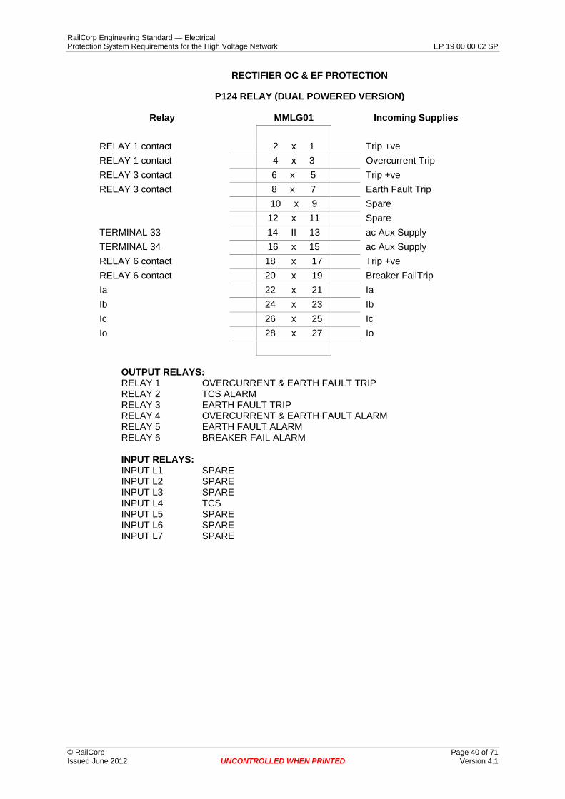
RailCorp Engineering Standard — Electrical Protection System Requirements for the High Voltage Network EP 19 00 00 02 SP
RECTIFIER OC & EF PROTECTION
P124 RELAY (DUAL POWERED VERSION)
Relay MMLG01 Incoming Supplies
RELAY 1 contact 2 x 1 Trip +ve RELAY 1 contact 4 x 3 Overcurrent Trip RELAY 3 contact 6 x 5 Trip +ve RELAY 3 contact 8 x 7 Earth Fault Trip
10 x 9 Spare 12 x 11 Spare
TERMINAL 33 14 II 13 ac Aux Supply TERMINAL 34 16 x 15 ac Aux Supply RELAY 6 contact 18 x 17 Trip +ve RELAY 6 contact 20 x 19 Breaker FailTrip Ia 22 x 21 Ia Ib 24 x 23 Ib Ic 26 x 25 Ic Io 28 x 27 Io
OUTPUT RELAYS: RELAY 1 OVERCURRENT & EARTH FAULT TRIP RELAY 2 TCS ALARM RELAY 3 EARTH FAULT TRIP RELAY 4 OVERCURRENT & EARTH FAULT ALARM RELAY 5 EARTH FAULT ALARM RELAY 6 BREAKER FAIL ALARM
INPUT RELAYS: INPUT L1 SPARE INPUT L2 SPARE INPUT L3 SPARE INPUT L4 TCS INPUT L5 SPARE INPUT L6 SPARE INPUT L7 SPARE
© RailCorp Page 40 of 71 Issued June 2012 UNCONTROLLED WHEN PRINTED Version 4.1

RailCorp Engineering Standard — Electrical Protection System Requirements for the High Voltage Network EP 19 00 00 02 SP
RECTIFIER OC & EF PROTECTION
MCAG33 RELAY
Relay MMLG01 Incoming Supplies
MCAG trip contact MCAG trip contact Spare trip contact Spare trip contact Spare Spare Spare Spare Spare Spare Ia Ib Ic Io
2 4 6 8 10 12 14 16
18 20 22 24 26 28
x x x x x x II x x x x x x x
1 3 5 7 9 11 13 15 17 19 21 23 25 27
MVAJ13 Trip +ve MVAJ13 Trip Spare trip contact Spare trip contact Spare Spare Spare Spare Spare Spare Ia Ib Ic Io
RELAY CONTACTS:
A∅ contacts: terminals 1 & 3 : trip 2 & 4 SCADA alarm
E/F contacts: terminals 5 & 7 : trip 6 & 8 SCADA alarm
C∅ contacts: terminals 9 & 11 : trip 10 & 12 SCADA alarm
Notes:
1. A & C phase trip contacts are connected in parallel at the relay terminals.
© RailCorp Page 41 of 71 Issued June 2012 UNCONTROLLED WHEN PRINTED Version 4.1

RailCorp Engineering Standard — Electrical Protection System Requirements for the High Voltage Network EP 19 00 00 02 SP
RECTIFIER TRANSFORMER FRAME LEAKAGE PROTECTION
MCAG14 RELAY
Relay MMLG01 Incoming Supplies
MCAG trip contact 2 x 1 Trip +ve MCAG trip contact 4 x 3 Trip Spare trip contact 6 x 5 Spare trip contact Spare trip contact 8 x 7 Spare trip contact Spare 10 x 9 Spare Spare 12 x 11 Spare Spare 14 II 13 Spare Spare 16 x 15 Spare Spare 18 x 17 Spare Spare 20 x 19 Spare IFL 22 x 21 IFL
IFL 24 x 23 IFL
Spare 26 x 25 Spare Spare 28 x 27 Spare
RELAY CONTACTS:
MCAG14 contacts: terminals 1 & 3: TRIP 2 & 4: SCADA alarm
© RailCorp Page 42 of 71 Issued June 2012 UNCONTROLLED WHEN PRINTED Version 4.1
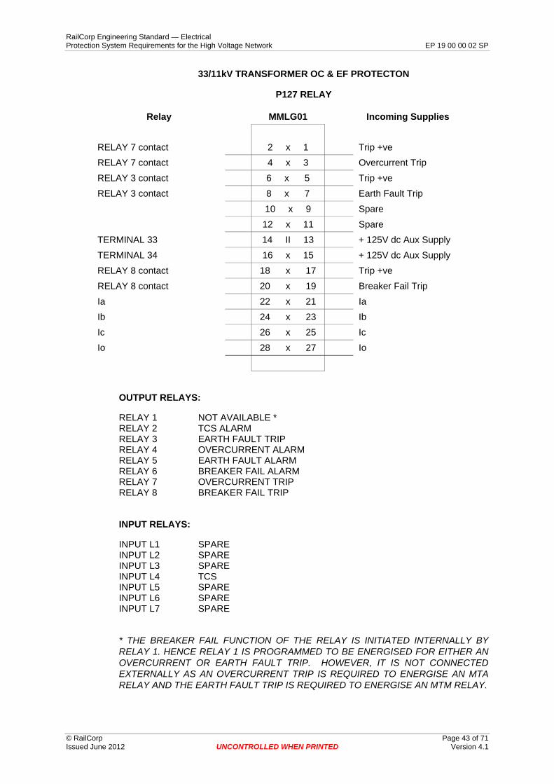
RailCorp Engineering Standard — Electrical Protection System Requirements for the High Voltage Network EP 19 00 00 02 SP
33/11kV TRANSFORMER OC & EF PROTECTON
P127 RELAY
Relay MMLG01 Incoming Supplies
RELAY 7 contact 2 x 1 Trip +ve RELAY 7 contact 4 x 3 Overcurrent Trip RELAY 3 contact 6 x 5 Trip +ve RELAY 3 contact 8 x 7 Earth Fault Trip
10 x 9 Spare 12 x 11 Spare
TERMINAL 33 14 II 13 + 125V dc Aux Supply TERMINAL 34 16 x 15 + 125V dc Aux Supply RELAY 8 contact 18 x 17 Trip +ve RELAY 8 contact 20 x 19 Breaker Fail Trip Ia 22 x 21 Ia Ib 24 x 23 Ib Ic 26 x 25 Ic Io 28 x 27 Io
OUTPUT RELAYS:
RELAY 1 NOT AVAILABLE * RELAY 2 TCS ALARM RELAY 3 EARTH FAULT TRIP RELAY 4 OVERCURRENT ALARM RELAY 5 EARTH FAULT ALARM RELAY 6 BREAKER FAIL ALARM RELAY 7 OVERCURRENT TRIP RELAY 8 BREAKER FAIL TRIP
INPUT RELAYS:
INPUT L1 SPARE INPUT L2 SPARE INPUT L3 SPARE INPUT L4 TCS INPUT L5 SPARE INPUT L6 SPARE INPUT L7 SPARE
* THE BREAKER FAIL FUNCTION OF THE RELAY IS INITIATED INTERNALLY BY RELAY 1. HENCE RELAY 1 IS PROGRAMMED TO BE ENERGISED FOR EITHER AN OVERCURRENT OR EARTH FAULT TRIP. HOWEVER, IT IS NOT CONNECTED EXTERNALLY AS AN OVERCURRENT TRIP IS REQUIRED TO ENERGISE AN MTA RELAY AND THE EARTH FAULT TRIP IS REQUIRED TO ENERGISE AN MTM RELAY.
© RailCorp Page 43 of 71 Issued June 2012 UNCONTROLLED WHEN PRINTED Version 4.1

RailCorp Engineering Standard — Electrical Protection System Requirements for the High Voltage Network EP 19 00 00 02 SP
NEUTRAL LEAKAGE PROTECTON
P127 RELAY
Relay MMLG01 Incoming Supplies
RELAY 1 contact 2 x 1 Trip +ve RELAY 1 contact 4 x 3 Neutral Leakage Trip
6 x 5 Spare 8 x 7 Spare 10 x 9 Spare 12 x 11 Spare
TERMINAL 33 14 II 13 + 125V dc Aux Supply TERMINAL 34 16 x 15 + 125V dc Aux Supply RELAY 8 contact 18 x 17 Trip +ve RELAY 8 contact 20 x 19 Breaker Fail Trip Ia 22 x 21 Ia Ib 24 x 23 Ib Ic 26 x 25 Ic Io 28 x 27 Io
OUTPUT RELAYS:
RELAY 1 NEUTRAL LEAKAGE TRIP RELAY 2 TCS ALARM RELAY 3 SPARE RELAY 4 NEUTRAL LEAKAGE ALARM RELAY 5 SPARE RELAY 6 BREAKER FAIL ALARM RELAY 7 SPARE RELAY 8 BREAKER FAIL TRIP
INPUT RELAYS:
INPUT L1 SPARE INPUT L2 SPARE INPUT L3 SPARE INPUT L4 TCS INPUT L5 SPARE INPUT L6 SPARE INPUT L7 SPARE
© RailCorp Page 44 of 71 Issued June 2012 UNCONTROLLED WHEN PRINTED Version 4.1

RailCorp Engineering Standard — Electrical Protection System Requirements for the High Voltage Network EP 19 00 00 02 SP
33/11kV TRANSFORMER (11KV SIDE)
OC & NEUTRAL LEAKAGE PROTECTON
P127 RELAY
Relay MMLG01 Incoming Supplies
RELAY 7 contact 2 x 1 Trip +ve RELAY 7 contact 4 x 3 Overcurrent Trip RELAY 3 contact 6 x 5 Trip +ve RELAY 3 contact 8 x 7 Neutral leakage Trip In 10 x 9 In In 12 x 11 In TERMINAL 33 14 II 13 + 125V dc Aux Supply TERMINAL 34 16 x 15 + 125V dc Aux Supply RELAY 8 contact 18 x 17 Trip +ve RELAY 8 contact 20 x 19 Breaker Fail Trip Ia 22 x 21 Ia Ib 24 x 23 Ib Ic 26 x 25 Ic Io 28 x 27 Io
OUTPUT RELAYS:
RELAY 1 SPARE RELAY 2 TCS ALARM RELAY 3 NEUTRAL LEAKAGE TRIP (TO MTA RELAY) RELAY 4 OVERCURRENT ALARM RELAY 5 NEUTRAL LEAKAGE ALARM RELAY 6 BREAKER FAIL ALARM RELAY 7 OVERCURRENT TRIP (TO 11KV ACCB) RELAY 8 BREAKER FAIL TRIP
INPUT RELAYS:
INPUT L1 SPARE INPUT L2 SPARE INPUT L3 SPARE INPUT L4 TCS INPUT L5 SPARE INPUT L6 SPARE INPUT L7 SPARE
© RailCorp Page 45 of 71 Issued June 2012 UNCONTROLLED WHEN PRINTED Version 4.1

RailCorp Engineering Standard — Electrical Protection System Requirements for the High Voltage Network EP 19 00 00 02 SP
11kV DISTRIBUTION TRANSFORMER OC & EF PROTECTION
VIP300LL RELAY
Relay MMLG01 Incoming Supplies
TERMINAL 15 2 x 1 Trip -ve TERMINAL 16 4 x 3 Trip +ve
6 x 5 Spare 8 x 7 Spare 10 x 9 Spare 12 x 11 Spare 14 II 13 Spare 16 x 15 Spare
TERMINAL 12 18 x 17 Ia TERMINAL 8 20 x 19 Ia TERMINAL 11 22 x 21 Ib TERMINAL 6 24 x 23 Ib TERMINAL 10 26 x 25 Ic TERMINAL 4 28 x 27 Ic
11kV DISTRIBUTION TRANSFORMER OC & EF PROTECTION
VIP300LL RELAY
Relay (x4 range 50-200A) MMLG01 Incoming Supplies
TERMINAL 15 2 x 1 Trip -ve TERMINAL 16 4 x 3 Trip +ve
6 x 5 Spare 8 x 7 Spare 10 x 9 Spare 12 x 11 Spare 14 II 13 Spare 16 x 15 Spare
TERMINAL 12 18 x 17 Ia TERMINAL 7 20 x 19 Ia TERMINAL 11 22 x 21 Ib TERMINAL 5 24 x 23 Ib TERMINAL 10 26 x 25 Ic TERMINAL 3 28 x 27 Lc
© RailCorp Page 46 of 71 Issued June 2012 UNCONTROLLED WHEN PRINTED Version 4.1

RailCorp Engineering Standard — Electrical Protection System Requirements for the High Voltage Network EP 19 00 00 02 SP
FEEDER DOC & DEF PROTECTION
P127 RELAY
Relay MMLG01 Incoming Supplies
RELAY 1 contact 2 x 1 Trip +ve RELAY 1 contact 4 x 3 Trip Va 6 x 5 Va Vb 8 x 7 Vb Vc 10 x 9 Vc Vn 12 x 11 Vn TERMINAL 33 14 II 13 + 125V dc Aux Supply TERMINAL 34 16 x 15 - 125V dc Aux Supply RELAY 8 contact 18 x 17 Trip +ve RELAY 8 contact 20 x 19 Breaker Fail Trip Ia 22 x 21 Ia Ib 24 x 23 Ib Ic 26 x 25 Ic Io 28 x 27 Io
OUTPUT RELAYS:
RELAY 1 OVERCURRENT & EARTH FAULT TRIP RELAY 2 TCS ALARM RELAY 3 SPARE RELAY 4 OVERCURRENT ALARM RELAY 5 EARTH FAULT ALARM RELAY 6 BREAKER FAIL ALARM RELAY 7 INTERTRIP SEND (IF REQUIRED) RELAY 8 BREAKER FAIL TRIP
INPUT RELAYS:
INPUT L1 SPARE INPUT L2 SPARE INPUT L3 SPARE INPUT L4 TCS INPUT L5 SPARE INPUT L6 SPARE INPUT L7 SPARE
© RailCorp Page 47 of 71 Issued June 2012 UNCONTROLLED WHEN PRINTED Version 4.1

RailCorp Engineering Standard — Electrical Protection System Requirements for the High Voltage Network EP 19 00 00 02 SP
FEEDER DOC & DEF PROTECTION
KCEG142 RELAY
Relay MMLG01 Incoming Supplies
KCEG142 trip contact 2 x 1 52 Trip +ve KCEG142 trip contact 4 x 3 52 Trip Va 6 x 5 Va Vb 8 x 7 Vb Vc 10 x 9 Vc Vn 12 x 11 Vn KCEG142 Aux 14 II 13 + 125V dc Aux KCEG142 Aux 16 x 15 - 125V dc Aux KCEG142 ACCB fail trip contact 18 x 17 ACCB/fail trip +ve
KCEG142 ACCB fail trip contact 20 x 19 ACCB/fail multitrip
Ia 22 x 21 Ia Ib 24 x 23 Ib Ic 26 x 25 Ic Io 28 x 27 Io
OUTPUT RELAYS:
RELAY 0 SPARE RELAY 1 BREAKER FAIL ALARM RELAY 2 SPARE RELAY 3 OVERCURRENT & EARTH FAULT TRIP RELAY 4 OVERCURRENT ALARM RELAY 5 EARTH FAULT ALARM RELAY 6 SPARE RELAY 7 BREAKER FAIL TRIP
© RailCorp Page 48 of 71 Issued June 2012 UNCONTROLLED WHEN PRINTED Version 4.1

RailCorp Engineering Standard — Electrical Protection System Requirements for the High Voltage Network EP 19 00 00 02 SP
TRANSFORMER DIFFERENTIAL PROTECTION
P632/MBCH RELAY
Relay MMLG01 Incoming Supplies
P632/MBCH trip contact 2 x 1 MVAJ Trip +ve
P632/MBCH trip contact 4 x 3 MVAJ Trip
Spare 6 x 5 Spare
Ia’’ (delta connected C.T’s) 8 x 7 Ia
Ib’’ (delta connected C.T’s) 10 x 9 Ib
Ic’’ (delta connected C.T’s) 12 x 11 Ic
P632/MBCH Aux 14 II 13 + 125V dc Aux
P632/MBCH Aux 16 x 15 - 125V dc Aux
Spare 18 x 17 Spare
Spare 20 x 19 Spare
Ia 22 x 21 Ia
Ib 24 x 23 Ib
Ic 26 x 25 Ic
Io 28 x 27 Io
OUTPUT RELAYS (P632):
TAP CHANGER PRESSURE SWITCHK901 TX DIFFERENTIAL TRIP K701 ALARM K902 RELAY HEALTHY K702 BREAKER FAIL ALARM K903 BREAKER FAIL TRIP K703 TAP CHANGER OIL SURGE ALARM K904 TX DIFFERENTIAL TRIP ALARM K704 SPARE K905 TX BUCHHOLZ GAS ALARM K705 SPARE K906 TX BUCHHOLZ OIL ALARM K706 SPARE K907 TAP CHANGER ALARM K707 SPARE K908 TCS ALARM K708 SPARE
INPUT RELAYS (P632):
U901 TAP CHANGER OIL SURGE OPERATION U902 TX BUCHHOLZ OIL SURGE OPERATION U903 TX BUCHHOLZ GAS OPERATION U904 TAP CHANGER ALARM
U701 TAPCHANGER PRESSURE SWITCH U702 TCS U703 SPARE U704 SPARE U705 SPARE U706 SPARE
© RailCorp Page 49 of 71 Issued June 2012 UNCONTROLLED WHEN PRINTED Version 4.1
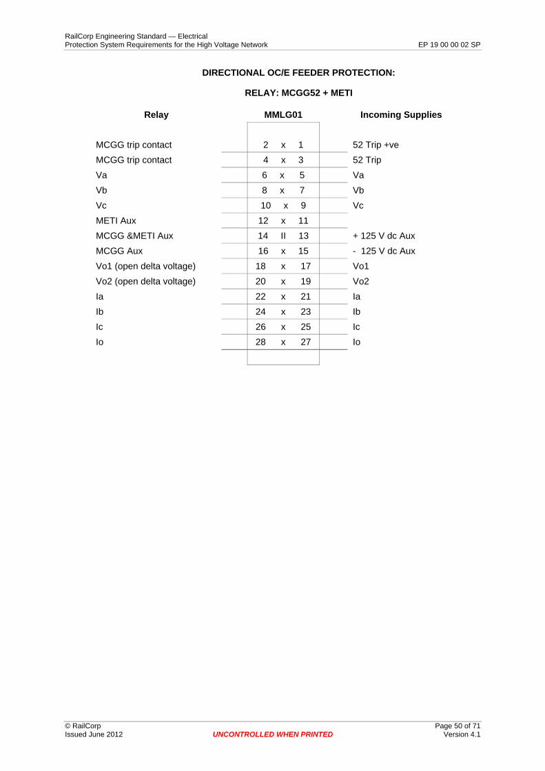
RailCorp Engineering Standard — Electrical Protection System Requirements for the High Voltage Network EP 19 00 00 02 SP
DIRECTIONAL OC/E FEEDER PROTECTION:
RELAY: MCGG52 + METI
Relay MMLG01 Incoming Supplies
MCGG trip contact 2 x 1 52 Trip +ve MCGG trip contact 4 x 3 52 Trip Va 6 x 5 Va Vb 8 x 7 Vb Vc 10 x 9 Vc METI Aux 12 x 11 MCGG &METI Aux 14 II 13 + 125 V dc Aux MCGG Aux 16 x 15 - 125 V dc Aux Vo1 (open delta voltage) 18 x 17 Vo1 Vo2 (open delta voltage) 20 x 19 Vo2 Ia 22 x 21 Ia Ib 24 x 23 Ib Ic 26 x 25 Ic Io 28 x 27 Io
© RailCorp Page 50 of 71 Issued June 2012 UNCONTROLLED WHEN PRINTED Version 4.1
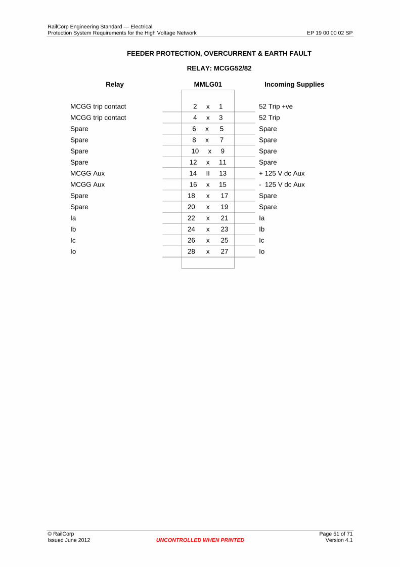
RailCorp Engineering Standard — Electrical Protection System Requirements for the High Voltage Network EP 19 00 00 02 SP
FEEDER PROTECTION, OVERCURRENT & EARTH FAULT
RELAY: MCGG52/82
Relay MMLG01 Incoming Supplies
MCGG trip contact 2 x 1 52 Trip +ve MCGG trip contact 4 x 3 52 Trip Spare 6 x 5 Spare Spare 8 x 7 Spare Spare 10 x 9 Spare Spare 12 x 11 Spare MCGG Aux 14 II 13 + 125 V dc Aux MCGG Aux 16 x 15 - 125 V dc Aux Spare 18 x 17 Spare Spare 20 x 19 Spare Ia 22 x 21 Ia Ib 24 x 23 Ib Ic 26 x 25 Ic Io 28 x 27 Io
© RailCorp Page 51 of 71 Issued June 2012 UNCONTROLLED WHEN PRINTED Version 4.1

RailCorp Engineering Standard — Electrical Protection System Requirements for the High Voltage Network EP 19 00 00 02 SP
BUS – TIE / BUS ZONE PROTECTION
MCAG34 RELAY
Relay MMLG01 Incoming Supplies
MCAG trip contact 2 x 1 Trip +ve MCAG trip contact 4 x 3 Trip Spare trip contact 6 x 5 Spare trip contact Spare trip contact 8 x 7 Spare trip contact Spare 10 x 9 Spare Spare 12 x 11 Spare Spare 14 II 13 Spare Spare 16 x 15 Spare Spare 18 x 17 Spare Spare 20 x 19 Spare Ia 22 x 21 Ia Ib 24 x 23 Ib Ic 26 x 25 Ic Io 28 x 27 Io
RELAY CONTACTS:
A∅ contacts: terminals 1 & 3 : trip 2 & 4 SCADA alarm
B∅ contacts: terminals 5 & 7 : trip 6 & 8 SCADA alarm
C∅ contacts: terminals 9 & 11 : trip 10 & 12 SCADA alarm
Notes:
1. A, B &, C phase trip contacts are connected in parallel at the relay terminals.
© RailCorp Page 52 of 71 Issued June 2012 UNCONTROLLED WHEN PRINTED Version 4.1

RailCorp Engineering Standard — Electrical Protection System Requirements for the High Voltage Network EP 19 00 00 02 SP
RECTIFIER LOCAL BACKUP PROTECTION
MVTT14 + MCTI39 RELAYS
Relay MMLG01 Incoming Supplies
MCTI trip contact 2 x 1 52 Trip +ve MCTI trip contact 4 x 3 52 Trip MCTI current check 6 x 5 CB/fail trip +ve MCTI current check 8 x 7 lLocal bu +ve 10 x 9 CAG33 contact MVTT start 12 x 11 CAG33 contact Local bu +ve 14 II 13 + 125V dc local bu Aux Local bu -ve 16 x 15 - 125V dc local bu Aux MVTT Breaker fail trip contact 18 x 17
MVTT Breaker fail trip contact 20 x 19 CB/fail multitrip
MCTI Ia 22 x 21 Ia MCTI Ib 24 x 23 Ib MCTI Ic 26 x 25 Ic MCTI Io 28 x 27 Io
© RailCorp Page 53 of 71 Issued June 2012 UNCONTROLLED WHEN PRINTED Version 4.1

RailCorp Engineering Standard — Electrical Protection System Requirements for the High Voltage Network EP 19 00 00 02 SP
Appendix I Voltage and Current Transducers Transducers that are to be used to provide the SCADA system with current and voltage information relating to the high voltage network shall have the following general characteristics:
• Output of 0…20mA • Mean sensing • Self powered
The following transducer is approved for connection in the protection current transformer circuit.
• Areva Istat 300; Type 3CAEA513AA (for CT’s with 1A secondaries) • Areva Istat 300; Type 3CAEA55GKA (for CT’s with 5A secondaries)
The following transducer is approved for connection in the voltage transformer circuit.
• Areva Istat 400; Type I4VAEA0-125, (nominal input range of 0-125V ac to measure a 110V ac voltage transformer output, usually measuring the voltage between A∅ & C∅).
© RailCorp Page 54 of 71 Issued June 2012 UNCONTROLLED WHEN PRINTED Version 4.1

RailCorp Engineering Standard — Electrical Protection System Requirements for the High Voltage Network EP 19 00 00 02 SP
Appendix J Pilot Wire Schemes
© RailCorp Page 55 of 71 Issued June 2012 UNCONTROLLED WHEN PRINTED Version 4.1
RailCorp Engineering Standard — Electrical Protection System Requirements for the High Voltage Network EP 19 00 00 02 SP
Appendix K Auto Re-close on High Voltage Feeders The RailCorp re-closure policy is as follows:
In general, one auto re-close in 5 seconds by SCADA (ie the master station initiates the auto re-close if all the requirements are met).
This policy applies to the following:
• 2kV, 11kV, 33kV 66kV aerial lines • 11kV, 33kV 66kV cables, no auto re-close • 2kV signalling cables do have auto re-close because of the criticality of maintaining
the supply and often the fault blows clear. • A feeder that is partially cable and partially aerial line is treated as aerial line.
During periods of total fire ban the auto re-close is inhibited on 33kV and 66kV feeders that traverse areas considered to be a bush fire risk . This is a master station function initiated by the ESO's.
Auto re-close is also automatically inhibited for 10 minutes after a close control.
© RailCorp Page 56 of 71 Issued June 2012 UNCONTROLLED WHEN PRINTED Version 4.1

RailCorp Engineering Standard — Electrical Protection System Requirements for the High Voltage Network EP 19 00 00 02 SP
Appendix L Protection SCADA Alarms
The following is a list of typical protection alarms required. The exact alarm requirement depends on the following factors:
• Type of relay • Capacity of RTU • Function of relay • Value adding of the alarm information to the EOC operator and RailCorp Protection
Engineer.
Refer to EP11 00 00 07 SP Design Technical Reviews for Electrical SCADA Equipment for further guidance and a typical example of a SCADA I/O schedule.
In many existing locations some of the protection alarms (eg. TCS) are connected in parallel for each piece of equipment to give one general alarm. This was due to the limitations on the quantity of alarms that could be connected to the RTU at the time of installation.
PROTECTION SCADA ALARMS ORIGIN OF ALARM SCADA ALARM NAME COMMENTS
ACCB SpringCharged LowGas LowGasLockOut MotorSupply MotorTrouble
The number of alarm stages will depend on the ACCB being installed.
PROTECTION RELAY DirectionProtectionA DirectionProtectionB DirectionProtectionC DirectionRelayFail DirectionalDCSupply PilotWireTripA PilotWireTripB PilotWireTripC BrokenConductorA BrokenConductorB BrokenConductorC PilotWireComms PilotWireRelayFail RelayCommFail OverCurrentA OverCurrentB OverCurrentC EarthLeakage InstOverCurrentA InstOverCurrentB InstOverCurrentC Inst_OC/ELtrip OverCurrentRelayFail BreakerFail NeutralLeakageProtection IntertripReceive
© RailCorp Page 57 of 71 Issued June 2012 UNCONTROLLED WHEN PRINTED Version 4.1

RailCorp Engineering Standard — Electrical Protection System Requirements for the High Voltage Network EP 19 00 00 02 SP
PROTECTION SCADA ALARMS ORIGIN OF ALARM SCADA ALARM NAME COMMENTS
IntertripSend BusZone1 BusZone2 BusZone3 BusZoneRelayFail DifferentialProtectionA DifferentialProtectionB DifferentialProtectionC DifferentialRelayFail TripCircuitSupervision SFORMER BuchholzGas
BuchholzOil TCBuchholzGas
TCBuchholzOil TCFail
TCLowLimit TCHighLimit TCControlSupply
These alarms originate from the transformer tap changer.
TCInProgress TCIncomplete TCRefSupplyAlarm
TemperatureAlarm This alarm originates from the temperature indicators on the transformer. There could possibly be several stages.
VOLTAGE PhaseFailure This alarm originates from a dedicated phase TRANSFORMER
DirectionalAlarm failure relay connected to the output of the VT. This alarm originates from a LV circuit breaker that supplies the voltage to the specific directional protection relay.
DCCB Frame Leakage DCFrameLeakage BATTERY CHARGER BattChargerAC BattUnderVolts
BattOverVolts BattConnected
These alarms originate from the battery charger and the exact alarms available will depend on the battery charger.
© RailCorp Page 58 of 71 Issued June 2012 UNCONTROLLED WHEN PRINTED Version 4.1

RailCorp Engineering Standard — Electrical Protection System Requirements for the High Voltage Network EP 19 00 00 02 SP
Appendix M Implementation Of SCADA Alarms & Control The SCADA alarms and control to and from equipment can be implemented by hard wiring or using a high level interface such as a serial link.
Numerical protection relays can be used to convey the information by using discrete output relays or via serial links. However certain information is critical for system operation and must be independent on the protection relay or communication link to the RTU.
The following list details the SCADA alarms and control that are required to be hard wired to the RTU.
• ACCB control (both open and close) • ACCB indication (both open and closed) • ACCB DISCONNECTOR/ISOLATOR indication (all positions)* • EARTH SWITCH indication (both open and closed)* • Tapchanger control • Battery Charger alarms • Protection relay watchdog alarms • Trip Circuit Supervision (TCS), where provided by a dedicated TCS relay. • Analogues (current and voltage) • Phase failure relay
* If all circuit breakers on a switchboard are not fitted with numerical relays having adequate RS485 communications to the RTU
© RailCorp Page 59 of 71 Issued June 2012 UNCONTROLLED WHEN PRINTED Version 4.1

RailCorp Engineering Standard — Electrical Protection System Requirements for the High Voltage Network EP 19 00 00 02 SP
Appendix N Typical ACCB Auxiliary Supply Arrangement
© RailCorp Page 60 of 71 Issued June 2012 UNCONTROLLED WHEN PRINTED Version 4.1
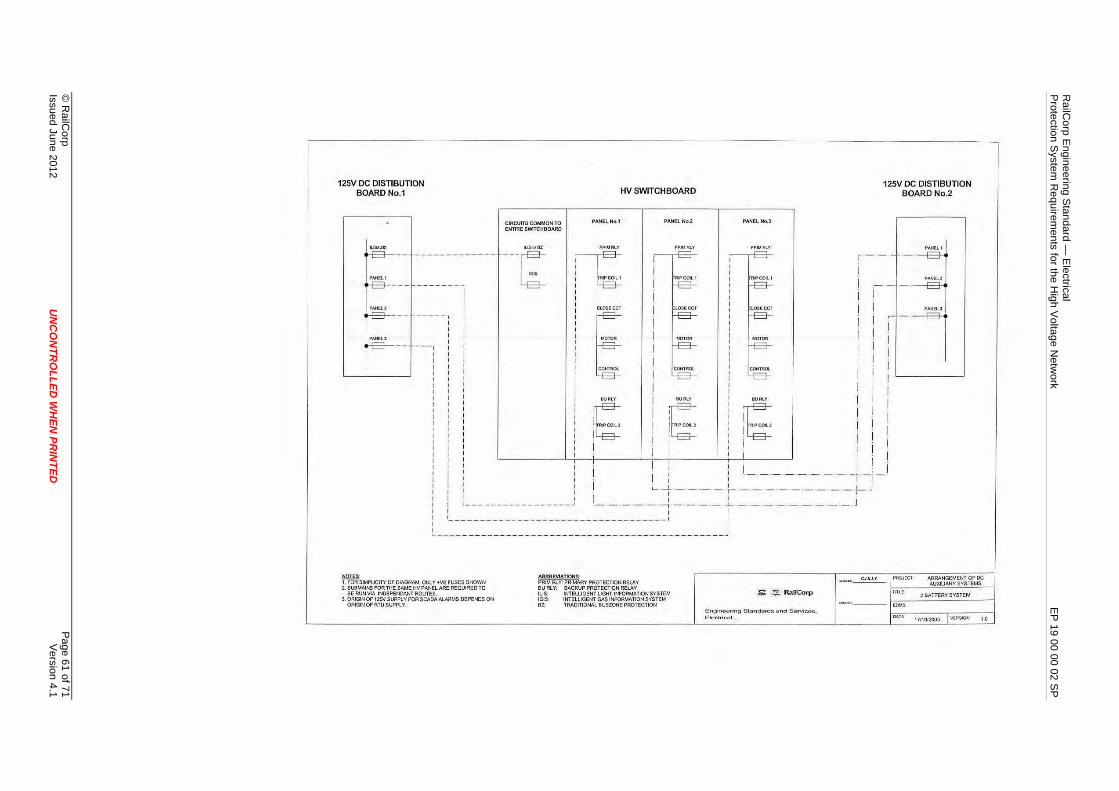
1 of 71ion
4.16s
Page V
er©
RailC
orp Issued June 2012
UN
CO
NTR
OLLED
WH
EN PR
INTED
125V DC DISTIBUTION BOARDNo.1
CIRCUITS COMMON TO ENTIRE SWITCHBOARD
ILISorBZ
---~
HV SWITCHBOARD
PANELNo.1 PANEL r.;o.2
PRlM Rl.Y PRltl. Rl,.Y
PANEi..No.J
125V DC DISTIBUTION BOARDNo.2
r"'11tL 1 I r -- -·-B-;
i i I
-----, I E E E i ~I-·~· : : ! ! i : : MOTOR I MOl OR MOTOR I I
- --: : : I j I I I I I . : : : CO«TROL CON1Rot. COtlfROC.. i l I I I I I I i / : I I
i i i OU•LV ~BURLY G'"~' : : I I I I -: : : FUPCOl.2 I RIPCOU ! ! I I I . I I I I I I I . . : : : : I I I : : I I I I I I i : : : I I : I -------- -t·-J-: : i I '-- -t - ·-·- - :-- - - - ·- - - ·- -·-·f-·J r : 1 __ _______________ J t_ -·-·-·- ·-l - __ ___ 1- - -- ·- _ __ ______ J I I I I
I !----------------------------------- ' I I I I I ~-------- - -------------------------- --------- --~
= · ~· 1. FOR SIMPllCITY OF DIAGRAM , Ot"i.Y ~ ve FUSES SHOWN PRIM Rl.Y: PRIMARY PROTECTION RELAY
au Rl Y: BACKUP PROTECTION RELAY
.,......,.~
2. SUBMAlNS FOR f t-iE SAME HV PANEL ARE REQUIRED TO BE RUN VIA lNOEPENOAtn ROUTES.
3. ORIGlNOf 125V SUPPl Y FOR SCAOAALARMS DEPENDS Qt' ORIGIN Of RTU SUPPLY.
IL!S; INTELLIGENT LIGHT INFORMATION SYS TEM IGIS: 111/TElllGENT GA.5 INFORMATION SYSTEM OZ: TRADITIONAL BUSZONE PROTECTION
& !:E R.'lilCorp
E n g inuurlng Sk111d{lrd~ tmd SorvlCOG, E l t,>ctric.al.
tC».IS
ARRANGEMENT OF DC AUXILIARY SYSTEMS
2 BATTERY SYSTEM
17110/2005 I V(ll:SION 1 0
RailC
orp Engineering S
tandard — E
lectrical P
rotection System
Requirem
ents for the High V
oltage Netw
ork E
P 19 00 00 02 S
P

RailCorp Engineering Standard — Electrical Protection System Requirements for the High Voltage Network EP 19 00 00 02 SP
Appendix O Protection Relay Labelling Guidelines The following rules apply to the labelling of protection relays and associated auxiliary relays:
• Location of Labels:
– Labels should be located above the relay. If this is not possible, then they should be located directly below the relay.
• Colour of Labels:
– All protection relays labels shall have black writing on a yellow background. – All auxiliary relays (such as multi-trip relays) shall have black writing on a white
background.
• Format
– To keep the length of labels to a minimum, abbreviations shall be used for the protection functions. The valid abbreviations are detailed in Table 12.
– All labels are to be in CAPITALS (except for abbreviations such as “Tx” & “kV”). – The description of equipment shall be consistent with terminology as used in the
AC operating diagrams. This is summarised below: – FEEDERS: “Feeder ID” ; – Where “Feeder ID” is the unique 3 digit identification assigned to each high
voltage feeder. – TRANSFORMERS: “Unit ID” + “voltage ratio” + “Tx” ; – Where “Unit ID” is the identification given where there are multiple transformers
(eg. No.1, No.2 etc). “voltage ratio” is the voltage ratio of the transformer usually expressed in kV (eg. 33/11kV, 66/33kV).
– RECTIFERS: “Unit ID” + “RECTIFIER” – Where “Unit ID” is the identification given where there are multiple rectifiers (eg.
No.1, No.2 etc).
• Content:
FIRST LINE OF LABEL:
The following sequence should be used to construct a label:
i) Equipment being Protected/Monitored
eg. No.1 RECTIFIER BUS ZONE 792 No.2 33/11kV Tx
ii) Type of Protection
eg. DOC & DE RELAY PW RELAY A∅ DOC RELAY A∅ OC RELAY FL RELAY Tx OC RELAY Tx DIFF RELAY
© RailCorp Page 62 of 71 Issued June 2012 UNCONTROLLED WHEN PRINTED Version 4.1
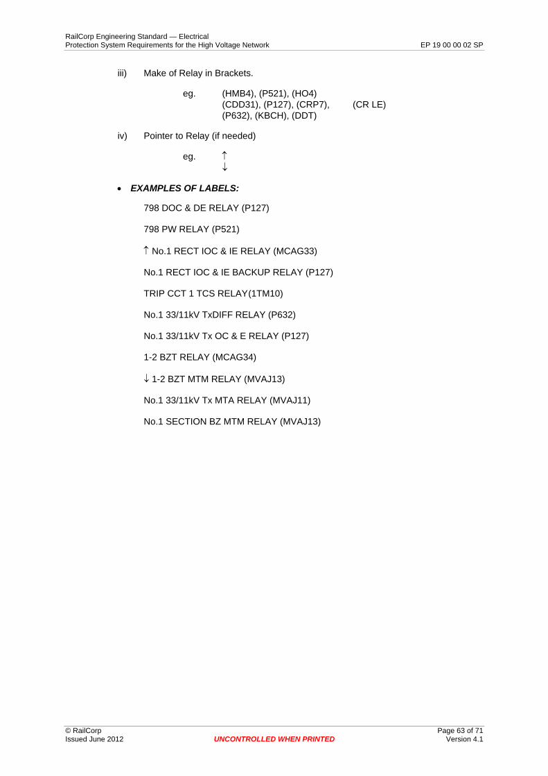
RailCorp Engineering Standard — Electrical Protection System Requirements for the High Voltage Network EP 19 00 00 02 SP
iii) Make of Relay in Brackets.
eg. (HMB4), (P521), (HO4) (CDD31), (P127), (CRP7), (CR LE) (P632), (KBCH), (DDT)
iv) Pointer to Relay (if needed)
eg. ↑ ↓
• EXAMPLES OF LABELS:
798 DOC & DE RELAY (P127)
798 PW RELAY (P521)
↑ No.1 RECT IOC & IE RELAY (MCAG33)
No.1 RECT IOC & IE BACKUP RELAY (P127)
TRIP CCT 1 TCS RELAY(1TM10)
No.1 33/11kV TxDIFF RELAY (P632)
No.1 33/11kV Tx OC & E RELAY (P127)
1-2 BZT RELAY (MCAG34)
↓ 1-2 BZT MTM RELAY (MVAJ13)
No.1 33/11kV Tx MTA RELAY (MVAJ11)
No.1 SECTION BZ MTM RELAY (MVAJ13)
© RailCorp Page 63 of 71 Issued June 2012 UNCONTROLLED WHEN PRINTED Version 4.1

RailCorp Engineering Standard — Electrical Protection System Requirements for the High Voltage Network EP 19 00 00 02 SP
PROTECTION FUNCTION ABBREVIATION ARC DETECTION AD
BUCHHOLZ B
BREAKER FAIL BF
BLOCKING RELAY BRly
BACKUP BU
BUS ZONE BZ
BUS ZONE TIE BZT
DIRECTIONAL EARTH FAULT DE
DIRECTIONAL INSTANTANEOUS OVERCURRENT DIOC
DIRECTIONAL OVERCURRENT DOC
EARTH FAULT E
DCCB FRAME LEAKAGE FLDC
AC FRAME LEAKAGE FL
RECTIFIER FRAME LEAKAGE FLR
INSTANTANEOUS EARTH LEAKAGE IE
INTELLIGENT GAS INFORMATION SYSTEM IGIS
INTELLIGENT LIGHT INFORMATION SYSTEM ILIS
INSTANTANEOUS OVERCURRENT IOC
INTERTRIP IT
INSTANTANEOUS & TIME DELAY OVERCURRENT ITOC
MUTI TRIP RELAY – AUTOMATIC RESET MTA
MULTI TRIP RELAY – MANUAL RESET (HAND) MTM
NEUTRAL LEAKAGE NL
OVERCURRENT OC
LOW OIL LO
OVERCURRENT & RESIDUAL EARTH FAULT INVERSE TIME ORET
PRESSURE SWITCH PS
PILOT WIRE PW
DC REVERSE CURRENT RC
TRANSFORMER DIFFERENTIAL TxDIFF
TRANSFORMER WINDING TEMPERATURE WT
TRIP CIRCUIT SUPERVISION TCS
TRIP SUPPLY SUPERVISION TSS
Table 12 - Protection Function Abbreviations
© RailCorp Page 64 of 71 Issued June 2012 UNCONTROLLED WHEN PRINTED Version 4.1

RailCorp Engineering Standard — Electrical Protection System Requirements for the High Voltage Network EP 19 00 00 02 SP
Appendix P Standard Current Transformer Configurations
© RailCorp Page 65 of 71 Issued June 2012 UNCONTROLLED WHEN PRINTED Version 4.1

©
RailC
orp P
age 66 of 71Issued June 2012
UN
CO
NTR
OLLED
WH
EN PR
INTED
V
ersion4.1
TRIP DIRECTION .. "' .ti cih.~ ~ -
SUBSTATION ~Plll\.U --B US BARS _, ' "
C~I: ~~
~ ~
--:-
~
I '" ' "I l l::&,('A,OC~
211• 16 ~a
fill @ fill ~ ,__
MICOM ig fill P1 27 (B ~ ,__
RELAY fill ~ ~ ~ -fill ~ -~ ~ ~ ,, 6 ~ t
J~ t't.!IJ.W' TmE CURREHT~'ISFORMER ARRANGEMENT
~ ~ RailCorp j ,_, ReLAVI MICOM P1 'l7 • DIRECTIONAL SCMEME PROTECTION
Engineering S1andards and Services,
I I VERSION E tcctricaf Systoms DATE 26110/2000 3.0
RailC
orp Engineering S
tandard — E
lectrical P
rotection System
Requirem
ents for the High V
oltage Netw
ork E
P 19 00 00 02 S
P
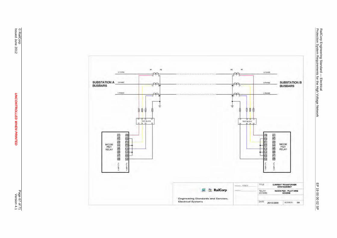
©
RailC
orp P
age 67 of 71Issued June 2012
UN
CO
NTR
OLLED
WH
EN PR
INTED
V
ersion4.1
.., P>
'""""'
SUBSTATIONA _:.•~""-:..::..~~~+-~~-F¥4+-~~~ BUSBARS
CPH-
CTJ ~' ~ ;:) " U.S18l~ 2! I
!ill ig
I 19
Mi COM fiS P521 RELAY §
~ ID! !!§
E. 0
r: " ~ i
s ~ RailCof"p
E ngineering Standards and Services, E loctrlcal Systoms
~ "'
~ ij ~
I ~ ~sr:or:
CJ,IU_Y
"""""" BPHASE
OP .....
, :; . ~
Tm.E
fill 19 19 ~ § ~ ID! ~ , ;:;
!
SUBSTATION B BUS BARS
MICOM P521
RELAY
CUMENT TllAASFORMeR ARRANGEMENT
1------ -F!EtAY/ SOEllE
MiCOM P521 - PILOT WIRE SCHEME
DAT!C 26110!2006 VERSION 3.0
RailC
orp Engineering S
tandard — E
lectrical P
rotection System
Requirem
ents for the High V
oltage Netw
ork E
P 19 00 00 02 S
P

RailCorp Engineering Standard — Electrical Protection System Requirements for the High Voltage Network EP 19 00 00 02 SP
Appendix Q Metering Requirements For Bulk Supply Points The following metering requirements are applicable to a RailCorp substation with indoor HV switchgear (AREVA/Schneider WSA GIS switchgear). These requirements are correct at the time of publication of this standard and should be confirmed with the relevant Supply Authority.
The requirements are based on the following documents:
Ausgrid: Metering Installations part A, Document ES3, September 2009
Endeavour Energy: Metering Design Instruction, Document No: MET 0002 (amendment 0)
Metering Requirements for Bulk Supply Points Interfacing with Ausgrid or Endeavour Energy.
VOLTAGE TRANSFORMERS:
• Dedicated winding required (1 per phase), class 0.5 and 50VA for Ausgrid, class 0.2 and 100VA for Endeavour Energy, form factor of 1.9/30s. Associated LV circuit breaker installed on the output with auxiliary contact of circuit breaker connected to SCADA.
• Warning label required adjacent to VT isolating handle (eg. "WARNING - VT SUPPLIES 7XX REVENUE METERING ").
CURRENT TRANSFORMERS:
• Dedicated set of metering class CT's with following parameters:
Ratio: identical to protection CT’s on same feeder
Designation: 15VA CLASS 0.5S,
Thermal limit current =2.0A,
Rated short-time current 31.5kA for 3s
• The CT's are required to be positioned adjacent to the metering CT's used for RailCorp check metering.
• Additional secondary wiring and associated CT links are required for connection to the new CT’s
CURRENT TRANSFORMER & VOLTAGE TRANSFORMER TEST RESULTS
The manufacturers test reports for the voltage transformers and current transformers are required to be submitted to RailCorp.
© RailCorp Page 68 of 71 Issued June 2012 UNCONTROLLED WHEN PRINTED Version 4.1

RailCorp Engineering Standard — Electrical Protection System Requirements for the High Voltage Network EP 19 00 00 02 SP
SECONDARY WIRING FROM 33KV SWITCHBOARD TO METER PANEL
• The CT & VT secondary wiring is required to be run in separate conduits to the new meter panel.
• The CT secondary wiring is to be a multi-core cable PVC/PVC minimum size of 2.5mm2
• The VT secondary wiring is to be a multi-core cable PVC/PVC minimum size of 2.5mm2 for Ausgrid and 4mm2 for Endeavour Energy.
240V AC SUPPLY TO METERING PANEL
• Dedicated 240Vac supply from the 415V DB required to be run in separate conduit to the metering panel.
• The 415V DB to have appropriate identification label and additional label "DO NOT TURN OFF" or similar adjacent to circuit breaker.
METERING PANEL
• The proposed location of the metering panel has to be approved by RailCorp prior to installation. The metering panel should be located on the external wall of the substation.
• The metering panel (including equipment) should be purchased directly from the Supply Authority where available.
© RailCorp Page 69 of 71 Issued June 2012 UNCONTROLLED WHEN PRINTED Version 4.1

RailCorp Engineering Standard — Electrical Protection System Requirements for the High Voltage Network EP 19 00 00 02 SP
Appendix R Current Transformer, Voltage Transformer and General Protection - Wire Identification Code
Letter Circuit function Wire numbers
A Current transformers for primary protection, excluding overcurrent
B Current transformer for busbar protection
C Current transformers for overcurrent protection (including combined earth-fault and instruments)
10-29 Red phase 30-49 White phase 50-69 Blue phase 70-89 Residual circuits and neutral current transformers
D Current transformers for instruments, metering voltage control
90 Earth wires directly connected to the earth bar
E Reference voltage of instruments, metering and protection 91-99
K Closing and tripping control circuits Any number from 1 upwards
L
Alarms and indications initiated by auxiliary switches and relay contact, excluding those for remote selective control and for general indication equipment
Any number from 1 upwards
T
Pilot conductors (including directly associated connections) between panels, independent of the distance between them, for pilot-wire protection, for inter-tripping or for both
Any number from 1 upwards
Notes:
If more numbers are required, add multiples of one hundred, e.g. 10-29 may be extended to 110-129, 210-229.
© RailCorp Page 70 of 71 Issued June 2012 UNCONTROLLED WHEN PRINTED Version 4.1

RailCorp Engineering Standard — Electrical Protection System Requirements for the High Voltage Network EP 19 00 00 02 SP
Appendix S Protection Non-Compliances Particular to the ECRL Project
This appendix details known design issues relating to the protection schemes and equipment installed in the ECRL project that do not comply with the general requirements of this standard.
These arrangements have been accepted for the ECRL project only.
11kV Protection
• Bus-zone protection not installed on the 11kV switchboards, (blocking scheme installed in lieu).
• Pilot wire protection not installed on the 11kV feeders. • Multi-trip relays not used. • Dual trip coils not installed. • Test blocks not wired in accordance with standard configuration. • Protection relays not programmed with standard configuration.
33kV Protection
• Multi-trip relays not used on the 33/11kV transformer protection (pushbutton installed to reset latched P632 output relays).
• Dual trip coils not installed. • Test blocks not wired in accordance with standard configuration. • Protection relays not programmed with standard configuration.
© RailCorp Page 71 of 71 Issued June 2012 UNCONTROLLED WHEN PRINTED Version 4.1