Embed Size (px)
Citation preview

Phone: Fax:
Email: Website:
+61 (0) 402 731 563 +61 (8) 9457 8642 [email protected] www.lifetime-reliability.com
The Lifetime Reliability Solutions
Certificate Course in Maintenance and Reliability
Module 4 – Precision Maintenance Techniques for Machinery
Session 18
Machine Installation – Shaft Alignment
1. Introduction
There is no dispute between vibration and reliability trainers, practitioners and commentators that
misalignment, and related problems, is the principal cause of problems in rotating machinery. It is
generally accepted that this is in the order of 50% of adverse vibration cases, it will of course vary
from industry to industry.
Attention to alignment issues alone would be a very productive place to start any reliability
programme.
Unlike bearings, there are no published standards for alignment tolerances. Those that have been
prepared have been by industry interest groups, such as API, or by trainers who have had access to a
wide input from industry as to what is effective and produces worthwhile results.
A popular misconception is that flexible couplings will accommodate misalignment without
detriment to other components in the machine, and adopt those criteria. The criteria given for
couplings is related to the transmission of the rated torque, they give no consideration to the
bearings or seals etc.
There are numerous problems which have an influence upon the final alignment result and it is
important to address these. Where these other issues have not been attended to an alignment task
can take many hours longer than one where they have been, and the final result is most probably not
so good or enduring.
There is a truth that correcting the contributory problems is probably more important, and
ultimately profitable, than the actual alignment itself.
This session will look at these related problems and at the techniques of alignment.
50-6010-15
30-40
Other Problems
Unbalance
Alignment Related

2
2. What is Misalignment and Why is it Important?
A Definition: Shaft misalignment is the deviation of relative shaft position from a colinear axis of
rotation measured at the points of power transmission when equipment is running at normal
operating conditions.
Defining Shaft Misalignment
For a flexible coupling to accept both parallel and angular misalignment there must be at least two
points where the coupling can flex to accommodate the misalignment condition. Measuring in the
horizontal and vertical planes produces four deviations, each of which must be within the specified
tolerance values.
Take the largest of these four deviations, measured in microns, and divide by the axial distance
between the points of power transmission, measured in mm; this gives the maximum deviation in
microns/mm.
There are three factors that influence alignment in rotating machinery;
The speed of the drive train,
The maximum deviation at either flexing point or point of power transmission,
The distance between the flexing points or points of power transmission.
The last part of the definition is probably the most difficult to achieve which is probably why it is
also the most often ignored – at normal operating conditions.
When the machine is started the shafts will begin to move to another position, with temperature
change being the most common cause. There are others such as process induced pipe forces and
counter-reactions due to the rotation of the rotor.
The objective of accurate shaft alignment is to increase the operating life of the machine. To
achieve this the machine components that are most likely to suffer failure must be operated within
their design specifications. Those most likely to fail are the bearings, seals, coupling and shafts –
and alignment has a significant influence on the life of each these, but particularly on the bearings.
3
Accurately aligned machinery will achieve:
Reduced axial and radial forces on the bearings to ensure longer bearing life,
Eliminate the possibility of shaft failure from cyclic fatigue,
Minimise the amount of wear on coupling components,
Minimise the amount of shaft bending from the point of power transmission in the coupling to
the coupling end bearing.
Maintain proper internal rotor clearances,
Reduce power consumption. This is a contoversial issue – some studies have shown savings
from 2% to 17% whist others have shown no measureable benefit.
Lower vibration levels on bearing housings, machine casings and rotors. But note that there are
instance where slight amounts of misalignment have resulted in reduced vibration levels. There
is a case for some caution about relating vibration amplitude to misalignment.
3. The Benefits of Alignment
There are now numerous recorded histories of companies who have addressed alignment issues and
obtained quite dramatic results;
improvements in vibration levels,
reduced mean time between failures
reduced maintenance costs.
Misalignment (microns/mm)

4
4. Types of Misalignment
5. Tolerances
The tolerances given in Table 1 are from a major company as part of their new equipment
specification. As seen against figure 2, they are very tight but indicate the companies drive for
excellence. Their tolerance for run out is a maximum of 0.050mm, regardless of the speed.
Table 1 Alignment Tolerances
Speed rpm
Parallel Offset mm/100mmof coupling
separation
Angularity mm/100mm of coupling diameter
Up to 1500 0.050 0.06
1500 to 3000 0.025 0.04
Over 3000 0.013 0.02
However, under these tolerances which consider measurement at the coupling it is possible to have
displacements at the bearing locations which are quite large. These shaft orbits can be large enough
to have a detrimental effect upon the life of bearings, seals, etc.
Table 2 gives tolerances as proposed by Update International, Inc of USA, and originate from
companies who have been successful in achieving high overall reliability, giving extended life to
other rotating components – seals, bearings.
Table 2 Alignment tolerances by Universal Technologies, Inc.
Machine Speed Maximum Offset at
Machine Feet
Maximum Offset at
Coupling Centreline
Up to 1500 rpm 0.050mm 0.025mm
Over 1500 rpm 0.025mm 0.013mm
Angular
Offset or
Parallel
Combination
5
It is possible to achieve an alignment condition which satisfies tolerances at the coupling but the
angularity can result in significant offsets at the feet. However, this standard controls the offset at
the feet and ensures a satisfactory alignment from the perspective of bearing and seal life.
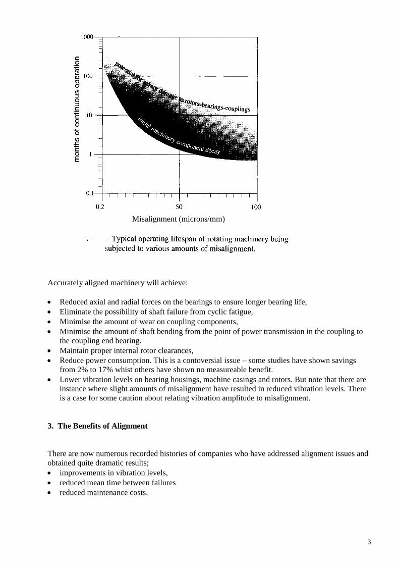
Misalignment Tolerance Guide for flexibly coupled rotating machinery.
Such tolerances should be included in maintenance department specifications for repaired and
overhauled machinery.
5. The Alignment Process
The alignment process can range from a simple periodic alignment check through to the full
procedure required when installing a new or rebuilt machine. The complete process may be
considered as a three part exercise;
Pre-Alignment
Rough In Alignment
Precision Alignment
and + or -.050
mm at feet + or - .025 mm
at the coupling

6
5.1 Pre-Alignment Checks and Corrections
There are numerous problems which have an influence upon the final alignment result and it is
important to address these. An alignment task where these other issues have not been attended to
can take many hours longer than one where they have been, and the final result is most probably not
so good or enduring.
There is a truth that correcting the contributory problems is probably more important, and
ultimately profitable, than the actual alignment itself.
5.1.1 Pre-Alignment checks focus on the following area:
unstable or deteriorated foundations and baseplates
damaged or worn components on the rotating elements; bearings, shafts, seals, couplings
excessive runout conditions; bent shafts, incorrectly bored coupling hubs
soft foot; machine casing to baseplate interface problems
excessive forces on attachments; pipework, ductwork, conduits
preparing machine for movement; hold down & jacking bolts, shims
5.1.2 RunOut describes eccentric(radial run out) or non-perpendicular (face run out) conditions
that exist between shafts and coupling hubs, impellers or other components rigidly fixed to the
shaft.
Run out is typically measured with a dial indicator and at several points along the length of a rotor.
Note that the amount of face run out will vary depending upon the radius of measurement. The table
below can be used as a guideline for acceptable amounts of run out.
Recommended Maximum Radial Run Out
Machine speed RPM Maximum Allowable Total
Indicator Run Out (TIR)
0 – 1500 0.125mm
1500 – 3000 0.050mm
3000 and above Less than 0.050mm
7
Check that the high spot and the low spot are 180o
apart, otherwise there may be confusions
with localised hills and valleys.
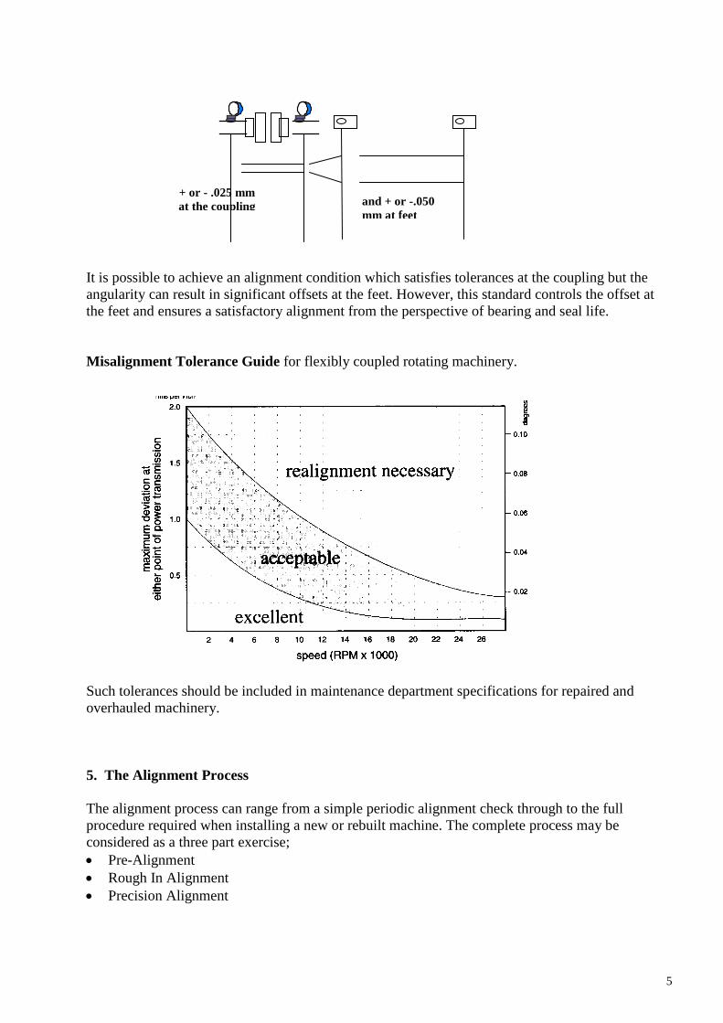
5.1.3 Soft Foot occurs when one or more of the feet are not making intimate contact with its
base/soleplate/frame. It is one of the more prevalent problems associated with alignment and can be
attributed to warped or bowed frames or machine cases, improper machining of equipment feet or
the baseplate, or any combination of these. It is more complex than the simple short leg on a four
legged chair analogy. The feet of a chair make point contact; machine feet are a (supposedly) flat
area and they have to make good contact with four (supposedly) flat surfaces on the baseplate. The
chances of all four feet and all four surfaces being truly flat and in the same plane are not good.
It is possible to have all four feet “soft”; this does not mean the machine is suspended in mid air. It
is quite likely that one or more feet are not parallel and that they are making only a point or edge
contact; in such a situation it will be necessary to make up a shim wedge to properly support the
foot.
There are three important reasons why this problem must be corrected:
The centre line of rotation of the shaft will move in a way that is dependant upon the sequence
of tightening the hold down bolts and will cause considerable frustration when trying to achieve
alignment.
Tightening down any of the hold down bolts that are not making good contact will cause the
machine case to warp upsetting critical clearances on components such as bearings, shaft seals,
mechanical seals, pump wear rings, compressor staging seals, motor stator/armature air gaps etc,
and inner alignments such as in gearing.
A situation of stress induced resonance can occur, giving rise to excessive vibration levels.
Paint or Dirt/Grit Stack or Deck of Shims
Bent or Burred Shims

8
5.2 Rough-In Alignment
At this stage the centrelines of the machines are brought into close proximity. There are no set rules
for this but as a general guide line they should be within 1mm offset at the coupling and
1mm/100mm angularity vertically and horizontally. Much depends upon the type of machine and
the experience of the person doing the job.
At the commencement of this work it is a good practice to commence with
a 3mm shim under each foot so that there is good provision for adjustment vertically
hold down bolts in the centre of their holes so that there is good provision for adjustment
horizontally.
Methods used for the rough-in alignment;
Straight edge across the coupling
Straight edge across the coupling with feelers
Unfortunately, this is so often where the job ends.
When aligning machinery, do not insist that one machine will be stationary; look for the common
line that gives minimal movement by each machine.
In working with trains of more than two units it is important to identify the line of the whole train so
that the best axis common to all may be selected. If consideration is not given to this it is quite
conceivable that after aligning the first two units the third will require corrections beyond its
physical limits.
Once the centrelines of rotation have been determined and the
allowable movement envelope illustrated on the graph, identify the
most efficient solution for movement
Stationary Movable Choices

9
5.3 Precision Alignment
A precision alignment will only be achieved with dial indicators or laser. If the preceding work has
been done well this final stage should be free of difficulties and for most machines take only a few
hours.
The alignment methods available at this stage include;
Rim and Face Dial Indicator
Reverse Dial Indicator
Laser.
Each precision alignment method has its own unique problems and there are also problems which
are unique to all methods.
Problems common to all methods include:
Loose fixtures, giving unrepeatable readings
Looseness, or excessive clearance, within the bearings
Dial Indicator Systems
Rim and Face
Reverse Dial Indicator
Dial Indicator methods are made more accurate by measuring from a shaft mounted “target” rather
than from directly on the shaft or coupling where there may be imperfections which can lead to
error.
10
Problems common to Dial Indicator systems include;
Bar Sag
Indicators set at an angle
Sticky indicators
Reading from the correct indicator
Indicator reading errors
Positive or negative
Did it start one way and go back?
Did it go all the way round?
Parallax
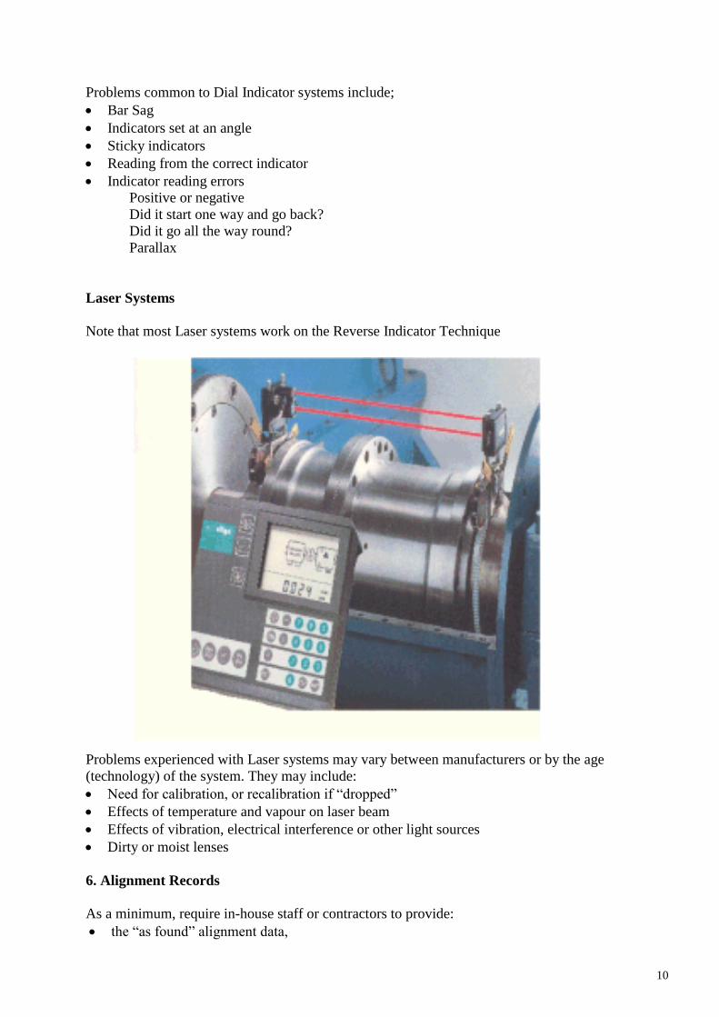
Laser Systems
Note that most Laser systems work on the Reverse Indicator Technique
Problems experienced with Laser systems may vary between manufacturers or by the age
(technology) of the system. They may include:
Need for calibration, or recalibration if “dropped”
Effects of temperature and vapour on laser beam
Effects of vibration, electrical interference or other light sources
Dirty or moist lenses
6. Alignment Records
As a minimum, require in-house staff or contractors to provide:
the “as found” alignment data,
11
soft foot conditions and the corrections made,
shaft and coupling hub run-out information,
the final alignment data,
the moves made on the machinery,
the final alignment tolerances.
This information must be recorded. It will be of significant benefit for future alignments and root
cause analysis.
When using contractors for alignment they should be used for the Precision stage only. Be satisfied
that the contractor has the skills and equipment necessary to achieve the results you expect.
Do not be satisfied with an answer like, “We used dial indicators and lasers.” Dial indicators and
lasers do not move machinery, - people do!!

12
Overview of Rotating Equipment Alignment Basics
Summarised from ‘Shaft Alignment Handbook’, John Piotrowsky, Revised and Expanded 2nd
Edition, Marcel Dekker, Inc
Benefits of accurate alignment:
Reducing excessive axial and radial forces on bearings means longer bearing life and rotor
stability
Eliminates possibility of shaft failure from cyclic fatigue
Minimize coupling components‟ wear
Minimise shaft bending from shaft coupling to nearest shaft bearings and maintain proper
internal rotor clearances
Reduce power consumption (cases of 2% to 17% power savings)
Lower vibration levels, though misalignment can cause vibration to reduce since shafts are
bent and bearings are pushed hard against housings and cannot move against the fluctuating
loads.
13
Foundations, Baseplates and Piping
Stability of the earth – earth acts as a giant shock absorber – is it rock or sand on which the
building stands?
Vibration is transmitted through the building and into all the equipment in the build – audible
„noise‟ created; brinnelling of bearings in stationary rotors; compaction of the ground causing
foundations to move; natural frequency effects
Foundations – Rigid or Floating
Rigid – most common
Advantages – Solid, stable platform using the surrounding soil to absorb vibration;
easier to construct, inertia block of concrete large enough to absorb vibration from
attached equipment
Disadvantages – degradation of foundation if outdoors; often unsupported piping
connected to machinery in expectation that machine frame will take loads;
foundations may settle; can absorb vibration from other machinery nearby
Floating – concrete slab sits on spring mounts (i.e. isolation mounts)
Advantages – when base plate and slab are connected together it allows equipment to
move if piping strain exists; isolates (somewhat) transmitting vibration into
supporting structure and from receiving vibration from machinery nearby.
Disadvantages – more difficult to construct and maintain; prolonged excessive
vibration does more damage to machine and attached piping; more difficult to align
and keep aligned
Baseplates
Typically cast or fabricated from structural steel
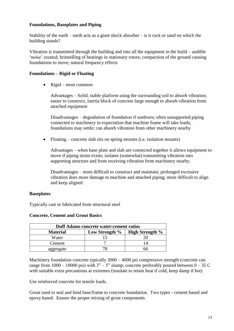
Concrete, Cement and Grout Basics
Duff Adams concrete water:cement ratios
Material Low Strength % High Strength %
Water 15 20
Cement 7 14
aggregate 78 66
Machinery foundation concrete typically 3000 – 4000 psi compressive strength (concrete can
range from 1000 – 10000 psi) with 3” – 5” slump; concrete preferably poured between 0 – 35 C
with suitable extra precautions at extremes (insulate to retain heat if cold, keep damp if hot)
Use reinforced concrete for tensile loads.
Grout used to seal and bind base/frame to concrete foundation. Two types - cement based and
epoxy based. Ensure the proper mixing of grout components.
14
Tips for Good Foundations
Inspect visually foundation and mountings every year against best-practice
requirements
o Pipe hangers take the weight, are properly positioned and have free
movement
o Pipe expansion joints move freely from thermal and hydraulic effects
o No loose piping flange bolts
o No cracked concrete bases or support columns
o No water seepage between baseplate and foundation that could freeze
o No chemical seepage between baseplate and foundation that could crystallise
or corrode
o No loose foundation bolts
o No corroded foundation bolts/nuts/washers
o No loose or rusty shims
o No loose or sheared dowel pins
o No paint on shims
Ensure natural frequency of foundation/supporting structure does not match
machinery running frequency by +- 20%, else harmonics are created. Build-in
options to de-tune structure if resonance does occur
Provide clearance for maintenance access and for machine/piping movement
Provide vibration isolating joints or air gaps between the foundation and the rest of
the building or floor structure
Where possible located fixing anchors centrally so baseplates can expand laterally
Minimise height of rotating centre of mass from the baseplate
Protect foundation from process generated heating with heat shields
Tips on Installing Foundations and Rotating Equipment
Use an experience and tested contractor or provide all the information on compaction,
steel reinforcement, concrete joints, concrete pouring and curing, grouting, etc
Chip away top ½” – 1” of previously poured concrete and thoroughly moisten before
pouring new concrete onto old, else new concrete in contact with old will not cure
properly as water of hydration is extracted into old concrete
Use concrete vibrators to extract air but not so much that large aggregate settle to bottom
of the pour
Check for baseplate distortion so that mounting pads are within 0.002” of each other
If baseplate distorted relieve stress by oven heating/annealing or vibratory impacting
shaker
Zinc coat baseplate against corrosion
Use ¾” or 1” jacking screws to level baseplates and not wedges, as wedges introduce
discontinuities into the grout
Grout from a 4” – 6” centre outwards toward 1” air vent holes (See API 610 for details)
Install vertical, lateral and axial jacking screws in the baseplate to permit all equipment
to be moved. Else leave sufficient space for jacks to be inserted to lift equipment for
shimming

15
Piping
The piping flanges on equipment were never designed to be load supporting. They are only
connection points for fluid transfer. The piping must itself be adequately supported in the
vertical, lateral and axial directions. Excessive piping force could:
Distort machine internals and clearances
Produce misalignment between equipment in a drive train
Cause hold-down bolts to loosen and/or shear
Brake cast frames and housings
Checking for excessive pipe stress
Align equipment, then fix dial gauge brackets on equipment shaft so two dial gauges in planes
90o apart measure the movement relative to the connecting shaft. Release hold-down bolts on
the equipment and ensure movement is no more than 0.002” on either dial gauge.
Equipment Level Ranges
Machinery Type Minimum Levelness Maximum Levelness
General process machinery
supported in antifriction
bearings
10 mils per foot 30 mils per foot
General process machinery
supported in journal bearings
(up to 500 hp)
5 mils per foot 15 mils per foot
Process machinery supported in
antifriction bearings 500 hp +
5 mils per foot 20 mils per foot
General process machinery
supported in journal bearings
500 hp +
2 mils per foot 8 mils per foot
Machine tools 1 mils per foot 5 mils per foot
1 mil = 0.001” = 0.0254 mm
On extremely long drive trains (e.g. power plant turbines, motor generator sets) the centenary curve is taken into consideration when aligning. The bow never becomes
perfectly straight and the shaft alignment must maintain the curve shape.
16
Off-line to Running (OL2R) Machine Movement
Virtually all machinery undergoes a change of position during start-up to running at operating
conditions. It becomes necessary to include the off-set when the alignment is done at „cold‟
conditions. In about 60% of RE this movement can be ignored as it is within limits. The
machines that are likely to be a problem are:
RE running at above 200 hp and 1200 rpm
Machinery that has change in casing temperature e.g. electric motors, steam turbines, gas
turbines, internal combustion engines
Speed changers e.g. gearboxes, mechanical speed reducers
Machinery pumping or compressing fluid where the fluid undergoes a temperature
change of 50o F or greater from intake to discharge
Equipment with poorly supported piping attached to the casing which expands and
contracts from thermal movement and process pressure fluctuations (water hammer)
producing a load on the equipment casing

17
Temperature changes from the process fluids through and across equipment are rarely uniform
and cause equipment to „pitch‟ at some angle rather than grow/shrink up/down and left/right.
Other causes of movement include changing environmental/weather conditions, pedestal
heating/cooling, piping movement, and casing reaction against rotating rotors or full load
conditions.
Most equipment undergo majority of changes shortly after start-up – typically 5 minutes to 1
hour – and may settle back a small amount once in operation.


![Temperature Monitoring System for Unbalance Phase · PDF filewinding insulation degradation process [2]. ... Temperature Monitoring System for Unbalance ... Effect on the motor when](https://img.pdfslide.us/doc/110x75/5aab293e7f8b9aa06a8b9a2f/temperature-monitoring-system-for-unbalance-phase-insulation-degradation-process.jpg)