Embed Size (px)
Citation preview

Énergie Transfert Thermique
Technical instructionsfor Operation & Maintenance
A different c l imateEnvironmental control solutions
Single fl ow heat pumpULTI+

2
E n e r g i eT r a n s f e r tT h e r m i q u e
Contents
Information contained in this document has been prepared by qualifi ed ETT specialists.We are doing our best to ensure its completeness and accuracy but it does not constitute a guarantee.This information is given in good faith, any use of the equipment not in accordance with the instructions and warnings is done at the user's own risk.
A. Equipment performance ................................................................................................................................ 3
B. Maintenance intervals ....................................................................................................................................... 3
C. Regulatory requirements ................................................................................................................................. 5
D. Specifi c maintenance recommendations ................................................................................ 7
E. Starting / Stopping the unit ........................................................................................................................... 8
F. Controller operation ............................................................................................................................................. 9
G. Diagnostics and troubleshooting support ...............................................................................10

Technical instructionsfor Operation & Maintenance
3MARK-NOT_20.00-EN
ETT may change equipment’s data & design without prior notice.Specifi cations given in this document are for information only and are not contractual.
A. Equipment performance• The validity of the guarantee is conditional upon strict compliance with instructions presented in this
document.• Proper operation and maintenance:
> maintain units’ performance; > extend equipment service life; > reduce the risk of unit failure; > allow energy costs management; > ensure regulatory compliance (compulsory checks based on local regulations).
ETT Services is here to help you get the most out of your installation.
+33 (0)2 98 48 02 [email protected]
Contact your local ETT Services adviser.
B. Maintenance intervals
Maintenance intervals: Q (Quarterly), H (Half-yearly), A (Annually)Operations T S A
General control Check casing X
Clean and prime siphons, clean condensate drains X
Read operating time X
Electricity / Control Check controller operation X
Set clock and operating schedule X
Check setpoints X
Electrical connections tightening X
Check temperature probes X
Consumables
Clean or replace fi lters (1)48 mm
X98 mm
X
Replace smoke detector headNota: Maintenance intervals are given as indication only. Replacement may be needed more frequently in polluted atmospheres.
Every 2 years
Replace smoke detection box battery Every 2 years
Replace humidity probe and/or sensor element (if applicable) Every 2 years
Replace CO2 probes (if applicable) Every 2 years

Technical instructionsfor Operation & Maintenance
4MARK-NOT_xx.00-EN
ETT may change equipment’s data & design without prior notice.Specifi cations given in this document are for information only and are not contractual.
Maintenance intervals: Q (Quarterly), H (Half-yearly), A (Annually)Operations T S A
Ventilation Check servomotors and dampers condition and operation X
Check fans turbines, clean if necessary X
Check air fl ow rates and fans rotation speed (if applicable)(1)
Nota: In case of insuffi cient fl ow rate, apply recommendations described in paragraph Specifi c maintenance recommendations, p. 7
X
Check air ducts (cone connectors, valves etc.) X
Read fans motors currents X
Check ventilation safety devices (fl ow rate, fi lters fouling, fi re contact, smoke detector, post-ventilation, etc.) (1) X
Refrigeration circuits Check oil level, adjust if necessary X
Check compressor(s) currents X
Check pressures: HP and LP X
Control superheat and subcooling X
Check fans turbines, clean if necessary (1) X
Check expansion valves operation, adjust if necessary X
Electronic expansion valves: check parameters X
Check 4-way valve(s) operation X
Check refrigeration safety devices (HP pressure switch, BP pressure switch function, thermostats, etc.) X
Tighten refrigeration pipe clamps: adjust or replace if necessary X
Regulatory controls Leakage checking (based on unit t CO2e) (2) >500 >50 >5
Pressure equipment inspection (2) Every 40 months
Pressure equipment certifi cation (2) Every 10 years
Inspection of air-conditioning systems and heat pumps (2) Every 5 years
Heating (if applicable) Check hot water coil (cleanliness, tightness) X
Check water quality in hot water coil X
Check 3-way valve operation X (3)
Check electric heaters operation X (3)
(1) See Specifi c maintenance recommendations.
(2) See Regulatory requirements.(3) In Heating mode.

Technical instructionsfor Operation & Maintenance
5MARK-NOT_20.00-EN
ETT may change equipment’s data & design without prior notice.Specifi cations given in this document are for information only and are not contractual.
C. Regulatory requirements
1/ Cooling system register (EN 378-2)
Each system having a refrigerant charge with a CO2 equivalent of 5 tonnes or above requires its own separate log book to be maintained.The logbook shall be prepared by the installer during installation. It shall be updated after every maintenance operation, as indicated in EN 378-4 standard.
Log books shall include the following information: > Detailed report of each maintenance or repair operation > Quantity and nature (new, reused, recycled) of refrigerant added during the operation > Quantity of refrigerant transferred during the operation (see also EN 378-4 standard) > Results of reused refrigerant analysis (if such analysis was performed) > Origin of reused refrigerant > System components replaced or modifi ed > Routine or periodic tests results > Signifi cant non-use periods
2/ Leakage checkingIn application of EU regulation No 517/2014 of the European Parliament and of the Council of 16 April 2014 on fl uorinated greenhouse gases and repealing Regulation (EC) No 842/2006 (Text with EEA relevance), equipment containing such refrigerants must be checked periodically for leakage (see Regulatory controls, p. 4) by certifi ed personnel and a tightness control certifi cate must be issued.
Leak check intervals
Checking frequency Once a year Twice a year 4 times a year
Metric tons of CO2 equivalent 5 to 50 50 to 500 > 500
Fluid
R134a Refrigerant charge (kg) 3.5 to 35 kg 35 to 349.7 kg >349.7 kg
R407C Refrigerant charge (kg) 2.82 to 28.2 kg 28.2 to 281.8 kg > 281.8 kg
R410A Refrigerant charge (kg) 2.39 to 23.9 kg 23.9 to 239.5 kg > 239.5 kg
3/ Refrigerant handlingRefrigerant handling must comply with French Decree no. 2007-737 and European legislation:
> Technicians must be trained and must hold the relevant F-gas qualifi cation. > The company employing the technician must hold an F-gas Company Certifi cate authorising its personnel to handle refrigerant. > Refrigerant leaks must be handled and declared according to the installation refrigerant charge.

Technical instructionsfor Operation & Maintenance
6MARK-NOT_xx.00-EN
ETT may change equipment’s data & design without prior notice.Specifi cations given in this document are for information only and are not contractual.
4/ Monitoring of pressure equipment operationAlthough refrigeration installations fall within the pressure equipment category, they are a special case in terms of in-service monitoring. In 2014, the French safety offi ce of industrial equipment (BSEI) validated a Technical Guidebook (CTP USNEF - Available on-line in French), which authorises waivers from the French decree of 15 March 2000 (amended).
> Refrigeration installations shall be verifi ed within 3 months of commissioning. Initial verifi cation shall be performed by an authorised person, under the responsibility of the operator.
> Refrigeration installations shall be inspected at least every 40 months. Periodic inspection shall be performed by an authorised person, under the responsibility of the operator.
> Refrigeration installations shall be requalifi ed every 10 years. Periodic requalifi cation shall be performed by an authorised body which shall issue a requalifi cation certifi cate. To avoid damage to the installation, the hydraulic test is not required.
5/ Inspection of reversible heat pumps and air-conditioning systemsDecree 2010-349 of 31 March 2010
The inspection shall include documentary controls and an assessment of system effi ciency and sizing compared with the cooling requirements of the building.
The inspection shall be performed: > by an authorised person; > at the owner's initiative; > at least every 5 years.
In case of replacement, the new equipment shall be inspected in the calendar year following replacement.

Technical instructionsfor Operation & Maintenance
7MARK-NOT_20.00-EN
ETT may change equipment’s data & design without prior notice.Specifi cations given in this document are for information only and are not contractual.
D. Specifi c maintenance recommendations
1/ Heat exchangers cleaningClean them using a bristle scrub brush, a vacuum or a compressed air jet if necessary. Rinse with cold and low pressure water, avoiding spatters on the fan motor. Clean in counter fl ow of the air fl ow way.Increase cleaning frequency if the equipment is exposed to corrosive/saline atmospheres.
2/ FiltrationPoor fi ltration or signifi cant fouling can affect unit effi ciency and damage the refrigeration circuit.
Nota:Filters can be cleaned 2 or 3 times. Beyond 3 regenerations, fi ltration performance is dramatically reduced.Filters should not be regenerated more than three times.If a fi lter cannot be regenerated, replace it.
• Metal fi lters regeneration > Clean the fi lter with warm water and liquid detergent. > Rinse thoroughly and dry using compressed air or air current. > Re-treat fi lter media with "fi lter-coat" or a similar product, to restore original performance. > Check that fi ltering elements are correctly installed when reassembling.
3/ Air fl ow rates control
Insuffi cient air fl ow rates can have several consequences: > The compressor operates out of the permitted operating range.
Ü Risk of compressor breakage > Heat from auxiliary heaters is not evacuated.
Ü Risk of fi re alarm > The setpoints are not reached.
Ü Lower heating capacity
In case of insuffi cient air fl ow rates: > Check supply air dampers operation > Check fi lters for fouling > Check exchangers for fouling > Check air ducts (fi re dampers, fouling in ducts, cone connectors)

Technical instructionsfor Operation & Maintenance
8MARK-NOT_xx.00-EN
ETT may change equipment’s data & design without prior notice.Specifi cations given in this document are for information only and are not contractual.
4/ Particularities of corrosive/saline atmospheres > Check and clean fans monthly. > Clean heat exchangers with clear water monthly.
5/ Actuating detector control > Operation must be controlled periodically, according to regulations applicable to the building. > For type 1 detectors (S6), the secondary source must be controlled every 3 months by holding the "secondary source test" button for at least 5 seconds. > The power indicator should remain lit. > Perform a functional test using an aerosol smoke detector tester. Follow manufacturer's instructions.
E. Starting / Stopping the unit
1/ Unit temporary shutdown > Stop the unit. > Do not shut off power to the compressor crankcase heater (if applicable) if the unit is installed in an area where the temperature is likely to fall below 0°C and if this operation is not handled automatically.
2/ Start-up after temporary shutdownNo special precautions are required. To start the unit, reverse the procedure outlined in Unit temporary shutdown, p. 8.
3/ Unit seasonal shutdown > If the heat pump includes water circuits, drain them. Also drain the connection lines if the unit is installed in an area where the temperature is likely to fall below 0°C. > Open the main power switch. Remove the fuse block or lock the main switch in opened position.
4/ Seasonal start-up > Perform annual maintenance operations according to Maintenance Intervals, p. 3. > Fill the water circuits and bleed the air out as necessary. > Control refrigeration circuit tightness. > Switch on the main power switch. > Acknowledge faults on the detection station, if applicable. > Allow the compressor crankcase heaters to preheat (72 hours), if applicable. > Start the system. > Check operation of all interconnected devices. > Check compressors oil level and refrigeration circuit(s) operating pressures after 15 to 20 minutes of operation.
Technical instructionsfor Operation & Maintenance
9MARK-NOT_20.00-EN
ETT may change equipment’s data & design without prior notice.Specifi cations given in this document are for information only and are not contractual.
5/ Generating set - EJP (peak load reduction)Equipment that can be powered by a generating set must be correctly stopped at each switch in power supply (mains <-> generating set).This can be managed manually, by dry contact or from the BMS (EJP switch).
Failure to comply with this recommendation could result in major damage to the unit or causecomponents to break (electrical components, compressors). In such circumstances, components are not covered by ETT guarantee.
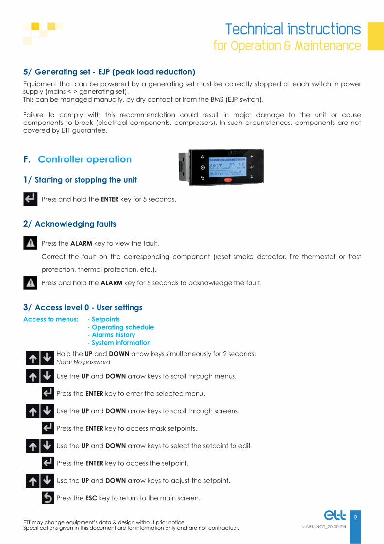
F. Controller operation
1/ Starting or stopping the unit
Press and hold the ENTER key for 5 seconds.
2/ Acknowledging faults
Press the ALARM key to view the fault.
Correct the fault on the corresponding component (reset smoke detector, fi re thermostat or frost
protection, thermal protection, etc.).
Press and hold the ALARM key for 5 seconds to acknowledge the fault.
3/ Access level 0 - User settingsAccess to menus: - Setpoints - Operating schedule - Alarms history - System information
Hold the UP and DOWN arrow keys simultaneously for 2 seconds.Nota: No password
Use the UP and DOWN arrow keys to scroll through menus.
Press the ENTER key to enter the selected menu.
Use the UP and DOWN arrow keys to scroll through screens.
Press the ENTER key to access mask setpoints.
Use the UP and DOWN arrow keys to select the setpoint to edit.
Press the ENTER key to access the setpoint.
Use the UP and DOWN arrow keys to adjust the setpoint.
Press the ESC key to return to the main screen.

Technical instructionsfor Operation & Maintenance
10MARK-NOT_xx.00-EN
ETT may change equipment’s data & design without prior notice.Specifi cations given in this document are for information only and are not contractual.
4/ Access level 1 - MaintenanceAccess to menus: - Level 0 - Inputs/Outputs - Meters - BMS communication
Hold the UP and DOWN arrow keys simultaneously for 2 seconds.Password, valid for one calendar year = 1 to 99, to be obtained from ETT Services.
Use the UP and DOWN arrow keys to scroll through menus.
Press the ENTER key to enter the selected menu.
Use the UP and DOWN arrow keys to scroll through screens.
Press the ENTER key to access mask setpoints.
Use the UP and DOWN arrow keys to select the setpoint to edit.
Press the ENTER key to access the setpoint.
Use the UP and DOWN arrow keys to adjust the setpoint.
Press the ESC key to return to the main screen.
G. Diagnostics and troubleshooting support
1/ Smoke fault
Possible reasons Corrective actions
Smoke detection
- Check for smoke or dust - Clean detector head - Replace detector head - Acknowledge the fault (See Acknowledging faults, p. 9)
Fouled detector head
- Check for smoke or dust - Clean detector head - Replace detector head - Acknowledge the fault (See Acknowledging faults, p. 9)
Battery back-up - Replace battery

Technical instructionsfor Operation & Maintenance
11MARK-NOT_20.00-EN
ETT may change equipment’s data & design without prior notice.Specifi cations given in this document are for information only and are not contractual.
2/ Filter fault
Possible reasons Corrective actions
Fouled fi lters - Clean fi lters - Replace fi lters
Fouled exchangers - Clean exchangers according to the recommendations
3/ Air fl ow fault
Possible reasons Corrective actions
Fouled fi lters - Clean fi lters - Replace fi lters
Leakage on air network - Repair air distribution network
Fouled air network - Clean air distribution network
Blocked pressure tap on fan - Check transparent tubes for water - With textile ducting, check cone diffusers
4/ Fire fault
Possible reasons Corrective actions
Insuffi cient air fl ow - Check fi lters - Check fan
Faulty thermostat - Check thermostat
5/ Antifreeze fault
Possible reasons Corrective actions
Insuffi cient air fl ow - Check fi lters - Check fan
Faulty thermostat - Check thermostat
Lack of hot water - Check boiler house and pumpNota: Water must keep fl owing in the hot water coil circuit.
6/ Supply air fan fault
Possible reasons Corrective actions
Drive fault - Check the type of fault on the maintenance terminal.
Nota: Switch off the power supply, wait for 2 minutes then switch it on again. If the fault persists, consult ETT Services.

Technical instructionsfor Operation & Maintenance
12MARK-NOT_xx.00-EN
ETT may change equipment’s data & design without prior notice.Specifi cations given in this document are for information only and are not contractual.
7/ Low pressure fault
Possible reasons Corrective actions
Poor air fl ow - Refer to Air fl ow fault, p. 11
Low pressure switch malfunction - Check low pressure switch parameters - Check LP probe connections
Fouled fi lters - Clean fi lters - Replace fi lters
Expansion valve malfunction - Check expansion valve (status, settings, operation) - Check overheating control parameters
Ineffi cient defrosting - Check refrigeration circuit probes - Check 4-way valve - Check defrost settings
Refrigerant charge problem - Leakage checking
8/ High pressure fault
Possible reasons Corrective actions
Poor air fl ow - Refer to Air fl ow fault, p. 11
High pressure switch malfunction - Check pressure switch operation - Check pressure switch connections
Fouled fi lters - Clean fi lters - Replace fi lters
Outside T° out of application range - The unit is not designed to operate in such conditions.
Poor air distribution - Check air distribution network
9/ Refrigeration circuit fault
9.1/ The compressor does not start.
Possible reasons Corrective actions
Electrical protection faults - Check protections
Control security - Check control parameters - Check securities - Reset controller if authorised
Abnormal supply voltage - Check phases - Check voltage drop at unit start-up - Check power supply chain (wire, connections, contactors, etc.)
Fan fault - Check fans

Technical instructionsfor Operation & Maintenance
13MARK-NOT_20.00-EN
ETT may change equipment’s data & design without prior notice.Specifi cations given in this document are for information only and are not contractual.
9.2/ The compressor stops.
Possible reasons Corrective actions
Low pressure fault - Refer to Low pressure fault, p. 12
High pressure fault - Refer to High pressure fault, p. 12
Ipsotherm fault - Check ipsotherm probe, if applicable - Check fi lters for fouling
Thermal fault - Check compressor's absorbed current - Check voltage drop at start-up
Power supply chain interruption - Check power supply chain (wire, connections, contactors, etc.).
Fan fault - Check fans
9.3/ The compressor is noisy.
Possible reasons Corrective actions
Knocks - Check compressor suction pressure
Slugging - Check charge (subcooling) - Check superheat - Check overheating control probe fastening
Grunts - Check supply voltage - Check phases - Galling → broken part
9.4/ The compressor does not stop.
Possible reasons Corrective actions
Temperature setpoint too far from recommended temperatures - Check temperature setpoints
Stuck contactor - Check contactor
9.5/ Lack of capacity.
Possible reasons Corrective actions
Evaporation temperature too low - Check overheating control parameters - Check charge
Severe overheating - Check overheating control parameters - Check charge - Check fl ow rates (Refer to Air fl ow fault, p. 11)
Pre-expansion - Check drier fi lter
Wrong fl ow rates - Check fl ow rates (Refer to Air fl ow fault, p. 11) - Check setpoints

www.ett.fr
Reference: MARK-NOT_20.00-EN56 Route de Brest - BP26 - 29830 PLOUDALMEZEAU - FranceTel: +33 (0)2 98 48 14 22 - Fax: +33 (0)2 98 48 09 12Export Contact: +33 (0)2 98 48 00 70 - ETT Services: +33 (0)2 98 48 02 22
Des
ign:
ETT
- D
ocum
ent p
rinte
d b
y an
env
ironm
enta
lly fr
iend
ly p
rinte
r usin
g ve
geta
ble-
base
d in
ks o
n PE
FC p
aper
cre
ated
from
sust
aina
bly-
man
aged
fore
sts.
A different c l imateEnvironmental control solutions
Énergie Transfert Thermique