Embed Size (px)
Citation preview
The Series PB410 HydroGuard® is a pressure-compensating mixer, which delivers a predetermined water temperature, compensating for pressure fluctuations in the hot or cold water supplies.The Series PB410 HydroGuard® features heavy, cast brass construction a poppet-type equalizing valve as part of a replaceable cartridge. The poppet-type construction offers a distinct advantage in that it will not stick because of lime build-up or foreign particles in the supplies. The adjustable metal-to-metal temperature limit stop prevents accidental scalding caused by over adjustment of the handle. It also features integral check stops, back-to-back and shallow wall installation capability.
Description n
The Series PB410 HydroGuard® is recommended in showers and bath and shower installations for motels, hotels, dormito-ries, health clubs and high rise apartment buildings.
Application n
Operation (See Figure 1) n
Connections: .......................................................................... 1⁄2" Sweat Inlets/Outlets
Capacity: ............................................................................................ 5.0 gpm (19L/min.)
Maximum Hot Water Supply Temperature: ....................................... 190°F (88°C)
Maximum Static Pressure: ........................................................... 125 psig (862 kPa)
Maximum Operating Pressure: .................................................... 125 psig (862 kPa)
High Temperature Limit Stop: ..................................... Metal to Metal, Adjustable
Certification: ................................................................................................... CSA B125
Listing: ............................................................................................................. ASSE 1016
Shipping Weight: ................................................................................ 4.5 lbs. (2.0 kg)
Specifications n
Series PB410 Pressure Balancing Mixing Valves Type PB413/Type PB417 (4 port)
Technical Instructions
IS-P-PB410
Model PB41700000
Hot and cold water enter their respective ports and the pressures are equalized through the action of the balance poppet. The entire balancing poppet assembly is contained in a Celcon cartridge. After the hot and cold pressures are equalized, they are mixed by the action of a mixing plate. As the temperature adjustment stem is rotated from shutoff to maximum hot water temperature, the mixing plate passes the required proportion of hot and cold water to produce the control point. With the adjustment stem in its full clockwise position, shutoff is obtained by closing both supplies.The temperature limit stop allows the user to set the maxi-mum discharge temperature. This mixer does not recognize supply water temperature changes, so any variation in the water temperature will affect the control point and the maxi-mum temperature setting.
Note: Installation should be in accordance with accepted plumbing practices. Flush all piping thor-oughly before installation.1. Position mixer 115⁄16" ± 1⁄2" [49mm ± 13mm] from inlet center to
finished wall surface. The tub outlet port is marked "TUB" and should face down. Facing front of mixer, connect hot water to left side and connect cold water to right side. The valve has "C" and "H" cast into the body near the appropriate inlet ports.
2. Valve is factory-set for standard inlets. If reversed inlets are required due to back-to-back installation (Cold water supply on the left and Hot water supply on the right), follow instruc-tions a–f below:
a. Connect cold inlet to hot port ("H") and hot inlet to cold port ("C"). Note: Do not turn valve upside down. If valve is upside down, water will not flow properly through tub spout or showerhead.
b. Turn water off with check stops. c. Loosen both temperature limit screws. d. Remove bonnet & stem e. Turn stem 180º, making sure notch or the stem is facing
downwards. f. While holding stem, tighten bonnet.Note: Be certain that valve opens in full cold! g. Hot and Cold inlets should be re-identified for reversed
inlets to avoid confusion during future maintenance.3. For tub and shower installations (see Figure 2). Pipe bottom
outlet port "TUB" directly to the diverter tub spout. The mixer body is designed to operate without the use of a twin ell. Pipe top outlet port to the showerhead.
4. For shower only installation (see Figure 3) pipe top outlet port directly to the showerhead and plug bottom port.
5. Rough-in guide installation… a. When piping installation is completed and before doing the
finished wall, slide rough-in guide onto the mixer stem and press fit into place (See Figure 4).
b. The rough-in guide will ensure the proper size opening for mixer and check stop shutoff and repair accessibility, as well as protect the chrome-plated sleeve from damage dur-ing drywall and tile installation.
6. After wall is completed, remove rough-in guide.7. Attach indicator plate gasket to the back of the dial plate
making sure horizontal holes match horizontal holes. Indicator plate locator hole matches diagonal hole on the plate. Peel off backing of dial gasket and attach to the inside top edge of the dial plate. Gasket should be approximately 1⁄16" beyond the plate edge.
8. Install the dial plate with the screws provided.9. Snap on the indicator plate. Guide on the back of the plate
goes into the locator hole.CAUTION: Indicator plate must be installed before sleeve.10. Install sleeve O-ring in the bonnet groove. Slide sleeve on the
bonnet.11. Install handle and tighten the setscrew.CAUTION: When soldering during installation process, do not heat the valve any higher than the temperature required to flow solder. Excessive overheating of the valve may cause damage to the cartridge mechanism. By following this recommendation, you will be able to solder the valve without removing either the cartridge or the checkstop internals. If either brazing or resis-tance (electric) solder is to be used, all valve internals must be removed.
Installation n
2
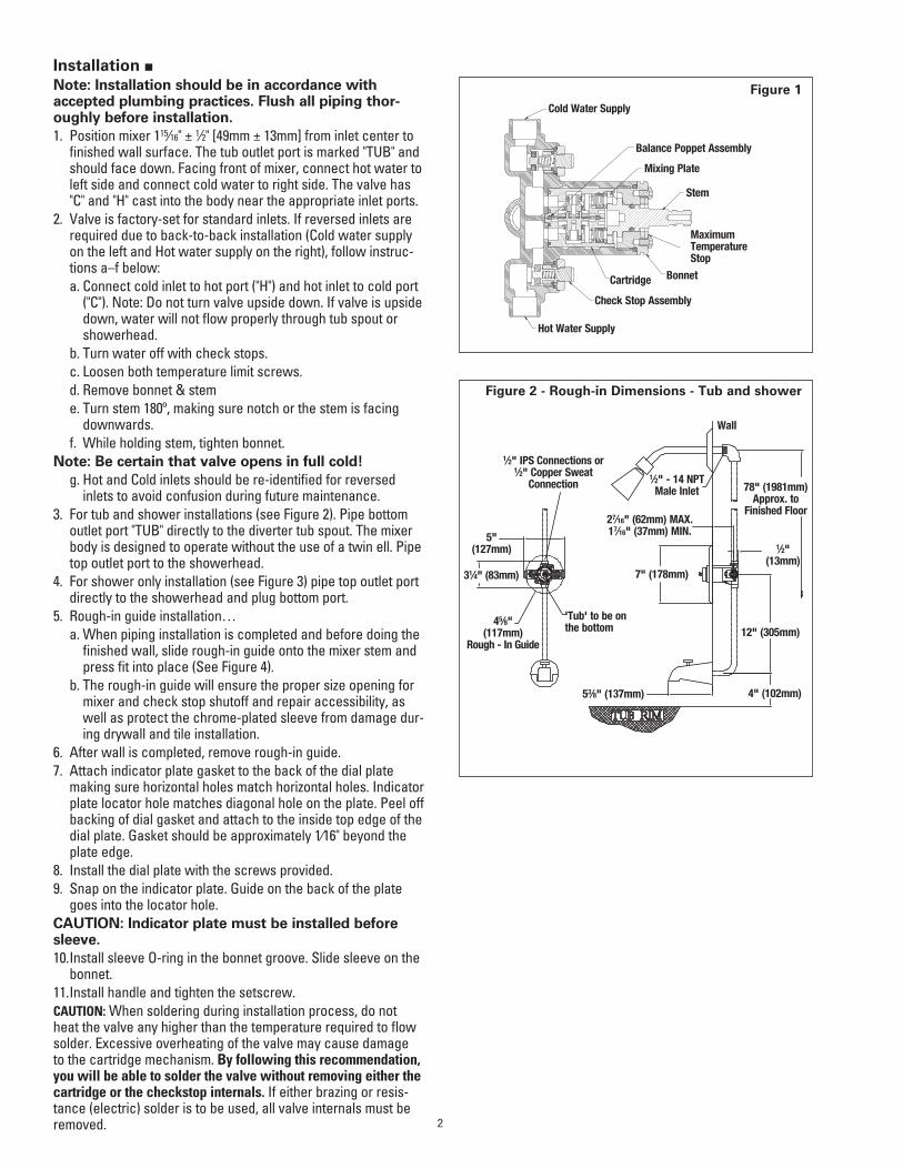
Figure 2 - Rough-in Dimensions - Tub and shower
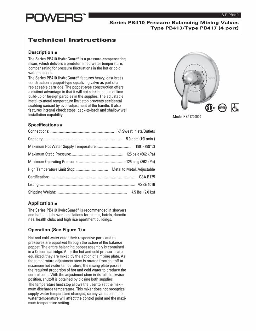
Figure 1Cold Water Supply
Stem
Maximum Temperature Stop
Check Stop Assembly
BonnetCartridge
Hot Water Supply
Wall
1⁄2" - 14 NPT Male Inlet
27⁄16" (62mm) MAX. 17⁄16" (37mm) MIN.
78" (1981mm) Approx. to
Finished Floor
1⁄2" (13mm)
12" (305mm)
53⁄8" (137mm)
7" (178mm)
'Tub' to be on the bottom45⁄8"
(117mm) Rough - In Guide
31⁄4" (83mm)
5" (127mm)
1⁄2" IPS Connections or 1⁄2" Copper Sweat
Connection
4" (102mm)
Balance Poppet Assembly
Mixing Plate
Installation Cont. n
Item No. Description Kit No.
1 Handle Kit 420 0492 Trim Plate Kit 410 0223 Sleeve Kit 220 0544 Bonnet/Stem Kit 410 4105 Cartridge 900 240
6 Check stop Replacement Kit 900 050
7 Body N/A
3
78" (1981mm) Approx. to
Finished Floor
1⁄2" (13mm)
24" (609mm) Approx.
Tub outlet TP be plugged. Plug by others.
7" (178mm)
27⁄16" (62mm) MAX. 17⁄16" (37mm) MIN.
1⁄2" - 14 NPT Male Inlet
'Tub' to be on the bottom
1⁄2" IPS Connections or 1⁄2" Copper Sweat
Connection
5" (127mm)
31⁄4" (83mm)
45⁄8" (117mm)
Rough - In Guide
Exploded view chart.
Figure 6
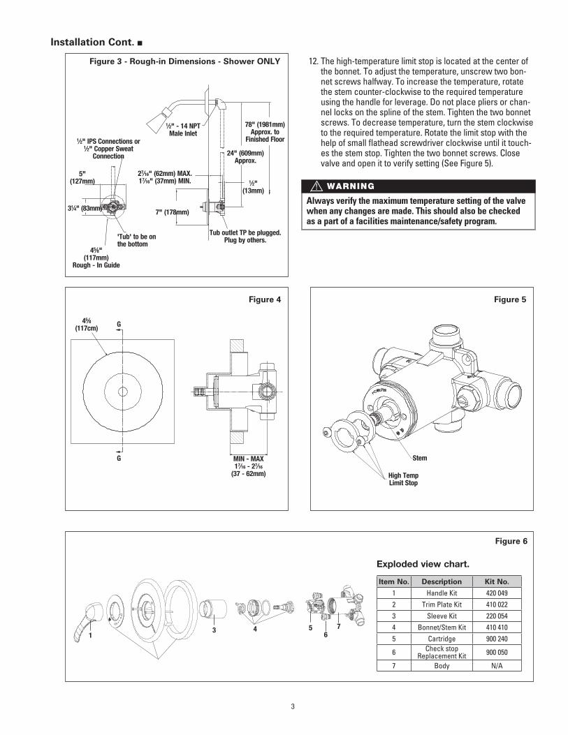
Figure 4 Figure 5
MIN - MAX17⁄16 - 27⁄16
(37 - 62mm)
G
G45⁄8(117cm)
High Temp Limit Stop
Stem
12. The high-temperature limit stop is located at the center of the bonnet. To adjust the temperature, unscrew two bon-net screws halfway. To increase the temperature, rotate the stem counter-clockwise to the required temperature using the handle for leverage. Do not place pliers or chan-nel locks on the spline of the stem. Tighten the two bonnet screws. To decrease temperature, turn the stem clockwise to the required temperature. Rotate the limit stop with the help of small flathead screwdriver clockwise until it touch-es the stem stop. Tighten the two bonnet screws. Close valve and open it to verify setting (See Figure 5).
13 4 5 7
6
Figure 3 - Rough-in Dimensions - Shower ONLY
Always verify the maximum temperature setting of the valve when any changes are made. This should also be checked as a part of a facilities maintenance/safety program.
WARNING!

Warranty n
The Seller warrants that the equipment manufactured by it and covered by this order or contract is free from defects in material and workmanship and, without charge, equipment found to be defective in material or workmanship will be repaired, or at Seller’s option replaced F.O.B. original point of shipment, if written notice of failure is received by Seller within one (1) year after date of shipment (unless specifically noted elsewhere), provided said equipment has been properly installed, operated in accordance with the Seller’s instructions, and provided such defects are not due to abuse or decomposition by chemical or galvanic action. ThiS expreSS warranTy iS in lieu OF and excludeS all OTher warranTieS, guaranTeeS, Or repreSenTaTiOnS, expreSS OF implied. There are nO implied warranTieS OF merchanTaBiliTy Or OF FiTneSS FOr a parTicular purpOSe. The Seller assumes no responsibility for repairs made on the Seller’s equipment unless done by the Seller’s authorized personnel, or by written authority from the Seller. The Seller makes no guarantee with respect to material not manufactured by it.
Maintenance and Troubleshooting n
USA: Phone: 1.800.669.5430 • Fax 1.847. 229.0526 • www.powerscontrols.comCanada: Phone: 1.888.208.8927 • Fax 1.888.479.2887 • www.powerscontrols.ca
IS-P-PB410 1232 EDP# 6512297 © 2012 Powers
A Watts Water Technologies Company
What to look for if:• The flow of water is less than desired. a. Valves upstream from supply not fully open. b. Low supply pressures. c. Accumulation of lime deposits in hot water pipes, restricting
the flow of hot water. d. Showerhead clogged. e. Checkstops may not be fully open. f. Low supply temperature (Hot Water).• Flow of water is completely shut off. a. Valves upstream from supply completely closed. b. Failure of hot or cold water supply pressure. The
HydroGuard® is constructed to restrict the flow of water on hot or cold water supply failure.
c. Checkstops closed.• Flow is untempered hot or cold water. a. The water supplies are connected to the wrong ports. b. Check for foreign material that may be clogging the car-
tridge.• Flow of water continues when HydroGuard® is
shut off. a. Worn shutoff discs. Replace cartridge. b. Scratched mixing plate. Replace Bonnet/Stem Kit. c. Erosion. Contact a Powers applications engineer to order
replacement parts.• Maximum temperature is too low. a. Accumulation of lime deposits in hot water pipes, which
restricts the flow of hot water. b. The concealed maximum temperature limit stop is not at its
maximum adjustment. Set the maximum temperature limit stop.
c. Hot water temperature is too low.