Embed Size (px)
Citation preview
July 2016
Model JP1Across the Line Start
Jockey Pump Controller
Technical Data Submittal Document
Contents:• Data Sheets • Dimensional Data• Wiring Schematics• Field Connections
Note: The drawings included in this package are for controllers covered under our standard offering. Actual AS BUILT drawings may differ from what is shown in this package.
Project: Customer: Engineer: Pump Manufacturer:
Technical Data Model JP1 Jockey Pump Controller
July 2016 2
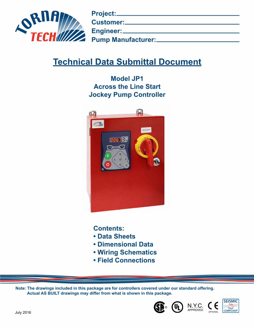
Listing
Underwriters Laboratory (UL) UL508A - Industrial Pump ControllersCSA CSA C22.2 No. 14 Industrial Control EquipmentNew York City Accepted for use in the City of New York by the Department of BuildingsSeismic Certification See page 4 for detailsOptional□ CE Mark Various EN, IEC & CEE directives and standards
Enclosure
Protection Rating□ Standard: NEMA 2 (IP31)Optional□ NEMA 12□ NEMA 3□ NEMA 3R□ NEMA 4
Accessories• Wall mounting lugs ( x4)
□ NEMA 4X-304 sst painted□ NEMA 4X-304 sst brushed finish□ NEMA 4X-316 sst painted□ NEMA 4X-316 sst brushed finish
Paint Specifications• Red RAL3002• Powder coating• Glossy textured finish
Starting Method: Full Voltage Across the line (Direct on line)Typical Voltage Applied at Start: 100%Inrush Current: 6 x normal load currentStarting Torque: 100%Motor Type: Across the line (Direct on line)No. of Contactors: 1 at 100% of horsepowerMin. ampacity of motor conductors: 3 at 125% x 100% of Full load Current (FLC)
JP1
JP2
M
M
M
JP3
Technical Data Model JP1 Jockey Pump Controller
July 2016 3
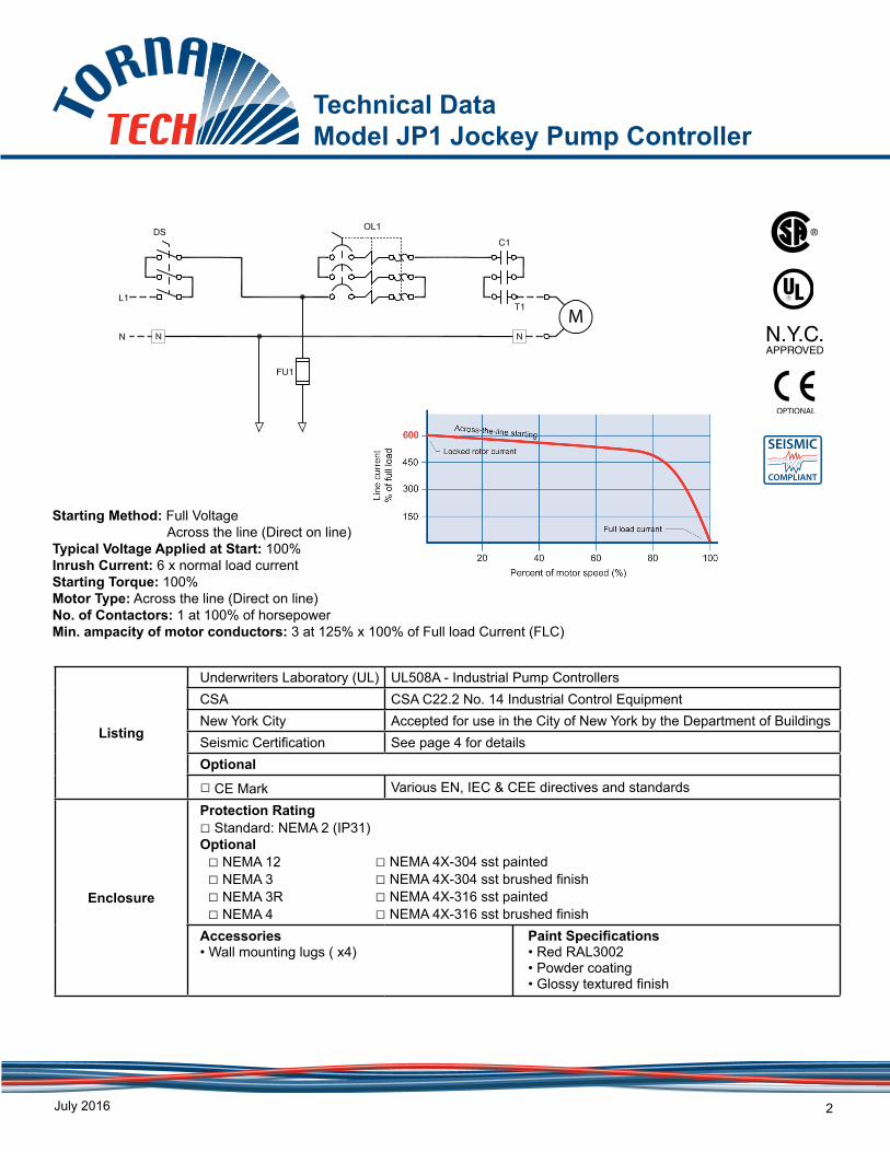
Fuseless Motor Starter
• Main disconnect – rotary type - door interlocked• Thermo-magnetic motor protector• Contactor
Control Circuit • 24V.AC
iPD+ Operator Interface
• Solid state controls• All adjustments on door front• Navigation pushbuttons
Pressure Sensing• Pressure transducer for fresh water application stainless steel construction• Rated for 0-600psi working pressure• Pressure sensing line connection ¼” Male NPT
Visual Indications
• Manual motor start/run LED• Automatic motor start/run LED• Motor overload• Pressure reading
• Start pressure• Stop pressure• System pressure
• System pressure diagnostic LED’s• Green: system pressure at or above stop pressure• Yellow: system pressure between start and stop pressure• Red: system pressure at or below start pressure
• AUTO mode• OFF mode
Timers• Minimum run timer (off delay)• Delay start timer (on delay)• Visual countdown
Counters • Pump start counter• Elapsed timer meter (hours / non-resettable)
Operators • OFF-AUTO pushbutton• Start and Stop pushbutton
Operation
Automatic Start Start on pressure drop
Manual Start Start pushbutton
Stopping Stop pushbutton
Timers Field adjustable & visual countdown
• Minimum run timer (off delay)• Delay start timer (on delay)
Technical Data Model JP1 Jockey Pump Controller
July 2016 4
0.1
1.0
10.0
0.1 1.0 10.0
Spe
ctra
l Res
pons
e A
ccel
erat
ion
(g)
Frequency, f (Hz)
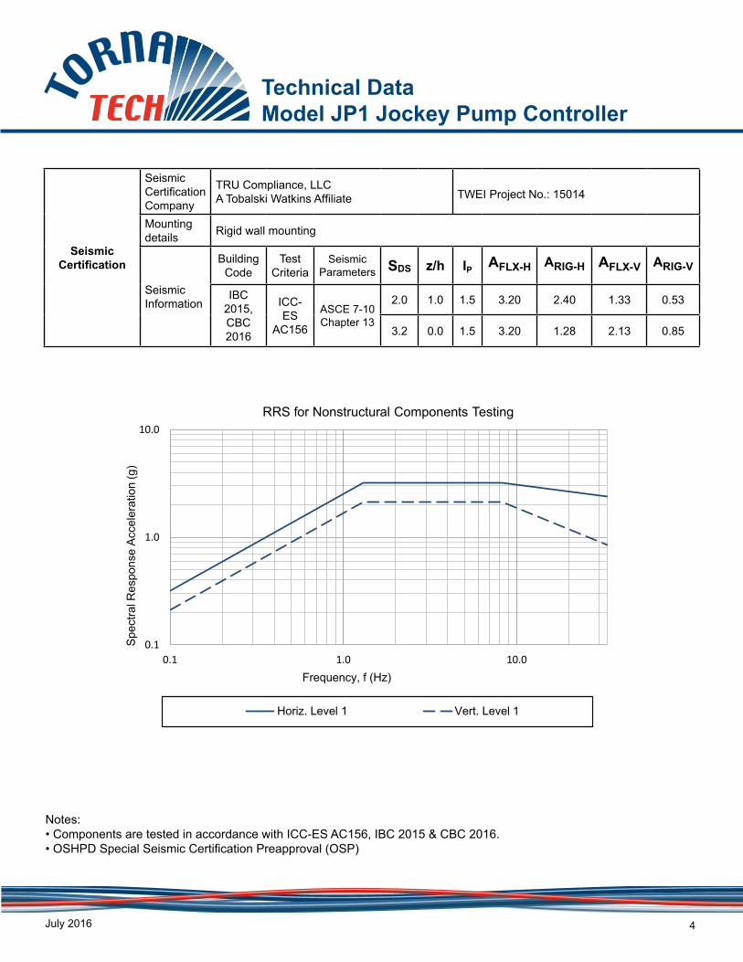
RRS for Nonstructural Components Testing
Horiz. Level 1 Vert. Level 1
Seismic Certification
Seismic Certification Company
TRU Compliance, LLCA Tobalski Watkins Affiliate TWEI Project No.: 15014
Mounting details Rigid wall mounting
Seismic Information
Building Code
Test Criteria
Seismic Parameters SDS z/h IP AFLX-H ARIG-H AFLX-V ARIG-V
IBC 2015, CBC 2016
ICC-ES
AC156
ASCE 7-10 Chapter 13
2.0 1.0 1.5 3.20 2.40 1.33 0.53
3.2 0.0 1.5 3.20 1.28 2.13 0.85
Notes:• Components are tested in accordance with ICC-ES AC156, IBC 2015 & CBC 2016. • OSHPD Special Seismic Certification Preapproval (OSP)
Technical Data Model JP1 Jockey Pump Controller
July 2016 5
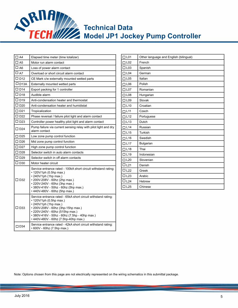
Note: Options chosen from this page are not electrically represented on the wiring schematics in this submittal package.
A4 Elapsed time meter (time totalizer)
A5 Motor run alarm contact
A6 Loss of power alarm contact
A7 Overload or short circuit alarm contact
D12 CE Mark c/w externally mounted wetted parts
D13A Externally mounted wetted parts
D14 Export packing for 1 controller
D18 Audible alarm
D19 Anti-condensation heater and thermostat
D20 Anti-condensation heater and humidistat
D21 Tropicalization
D22 Phase reversal / failure pilot light and alarm contact
D23 Controller power healthy pilot light and alarm contact
D24 Pump failure via current sensing relay with pilot light and dry alarm contact
D25 Low zone pump control function
D26 Mid zone pump control function
D27 High zone pump control function
D28 Selector switch in auto alarm contacts
D29 Selector switch in off alarm contacts
D30 Motor heater circuit
D32
Service entrance rated - 100kA short circuit withstand rating:• 120V/1ph (0.5hp max.)• 240V/1ph (1hp max.)• 200V-208V - 60hz (2hp max.)• 220V-240V - 60hz (3hp max.)• 380V-416V - 50hz - 60hz (5hp max.)• 440V-480V - 60hz (5hp max.)
D33
Service entrance rated - 65kA short circuit withstand rating:• 120V/1ph (0.5hp max.)• 240V/1ph (1hp max.)• 200V-208V - 60hz (3hp-15hp max.)• 220V-240V - 60hz (515hp max.)• 380V-416V - 50hz - 60hz (7.5hp - 40hp max.)• 440V-480V - 60hz (7.5hp-40hp max.)
D34 Service entrance rated - 42kA short circuit withstand rating:• 600V - 60hz (7.5hp max.)
L01 Other language and English (bilingual)
L02 French
L03 Spanish
L04 German
L05 Italian
L06 Polish
L07 Romanian
L08 Hungarian
L09 Slovak
L10 Croatian
L11 Czech
L12 Portuguese
L13 Dutch
L14 Russian
L15 Turkish
L16 Swedish
L17 Bulgarian
L18 Thai
L19 Indonesian
L20 Slovenian
L21 Danish
L22 Greek
L23 Arabic
L24 Hebrew
L25 Chinese
Technical Data Model JP1 Jockey Pump Controller
July 2016 6
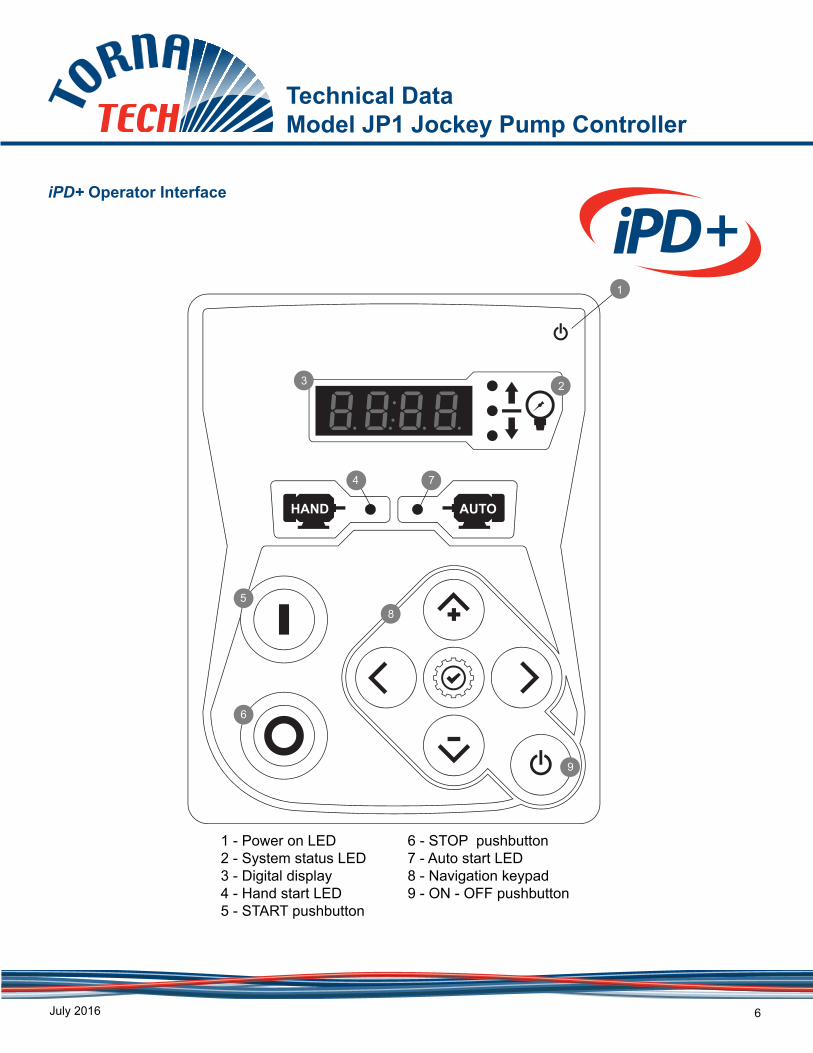
iPD+ Operator Interface
1 - Power on LED2 - System status LED3 - Digital display4 - Hand start LED5 - START pushbutton
6 - STOP pushbutton 7 - Auto start LED8 - Navigation keypad9 - ON - OFF pushbutton
AUTOHAND
9
5
6
3 2
1
8
74
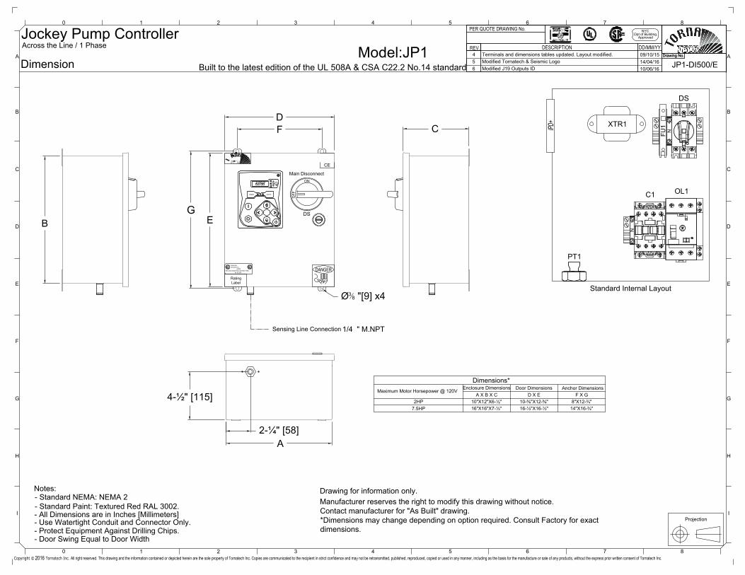
JP1-DI500/EModel
Dimension:JP1
Projection
NYCDpt of Building
Approved
Drawing No.
DD/MM/YYDESCRIPTION
PER QUOTE DRAWING No.
REV.
2HP7.5HP
A X B X C
16"X16"X7-½" 16-½"X16-½" 14"X16-¾"
D X E F X G10"X12"X6-½" 10-⅝"X12-⅝" 8"X12-¾"
Standard Internal Layout
Dimensions*Maximum Motor Horsepower @ 120V
Main Disconnect
RatingLabel
- All Dimensions are in Inches [Millimeters]- Use Watertight Conduit and Connector Only.- Protect Equipment Against Drilling Chips.
Notes:
Sensing Line Connection
DS
ON
OFF
DF C
2-¼" [58]
4-½" [115]
EG
1/4 " M.NPT
A
B
Ø38 "[9] x4
HAND AUTO
G
Y
R
GG
- Door Swing Equal to Door Width
ENCLOSED INDUSTRIAL CONTROL PANEL
Laboratories Inc.
No. AC-XXX
LISTED
Underwriters
CE
Across the Line / 1 Phase
Built to the latest edition of the UL 508A & CSA C22.2 No.14 standard
Jockey Pump Controller
DS
C1 OL1
PT1
FU1
N
N
XTR1
- Standard NEMA: NEMA 2- Standard Paint: Textured Red RAL 3002. Manufacturer reserves the right to modify this drawing without notice.
Contact manufacturer for "As Built" drawing.*Dimensions may change depending on option required. Consult Factory for exactdimensions.
Drawing for information only.
Drawing No.
DANGER
Enclosure Dimensions Door Dimensions Anchor Dimensions
3 4 5 6 72
G
H
0 1 8
B
C
D
E
F
I
A
3 4 5 6 720 1 8
G
H
I
A
B
C
D
E
F
2016Copyright © Tornatech Inc. All right reserved. This drawing and the information contained or depicted herein are the sole property of Tornatech Inc. Copies are communicated to the recipient in strict confidence and may not be retransmitted, published, reproduced, copied or used in any manner, including as the basis for the manufacture or sale of any products, without the express prior written consent of Tornatech Inc.
4 Terminals and dimensions tables updated. Layout modified. 09/10/15 4 Terminals and dimensions tables updated. Layout modified. 09/10/155 Modified Tornatech & Seismic Logo 14/04/16 5 Modified Tornatech & Seismic Logo 14/04/166 Modified J19 Outputs ID 10/06/16 6 Modified J19 Outputs ID 10/06/16
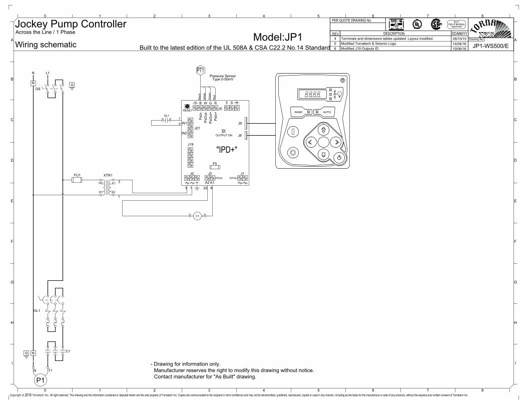
ModelWiring schematic JP1-WS500/E
3 4 5 6 72
G
H
0 1 8
B
C
D
E
F
I
A
3 4 5 6 720 1 8
G
H
I
A
B
C
D
E
F
2016Copyright © Tornatech Inc.
:JP1
NYCDpt of Building
Approved
Drawing No.
DD/MM/YYDESCRIPTION
PER QUOTE DRAWING No.
REV.
HAND AUTO
G
Y
R
GG
PsI
n-P
sOut
-P
sOut
+P
sIn+
A2
RESET
F5
"IPD+"
J2
J5
J8
J3 J1
J9
OUTPUT ON
RGWB 5 S
A1
G
22 8
24Vac24Vac
J19
3 1
J21IN2
IN1
OL1734 33
9
Bla
ck
Pressure Sensor
Whi
te
Gre
en
Red
Type 0-50mV
PT1
Across the Line / 1 Phase
N
P1
OL1
C1
FU1
X2
X1
XTR1
H1
H2 3
1
L1
DS
T1
N
N
NG
G
Built to the latest edition of the UL 508A & CSA C22.2 No.14 Standard
Jockey Pump Controller
C1A1 A2
Manufacturer reserves the right to modify this drawing without notice.Contact manufacturer for "As Built" drawing.
- Drawing for information only.
All right reserved. This drawing and the information contained or depicted herein are the sole property of Tornatech Inc. Copies are communicated to the recipient in strict confidence and may not be retransmitted, published, reproduced, copied or used in any manner, including as the basis for the manufacture or sale of any products, without the express prior written consent of Tornatech Inc.
4 Terminals and dimensions tables updated. Layout modified. 09/10/15 4 Terminals and dimensions tables updated. Layout modified. 09/10/15 4 Terminals and dimensions tables updated. Layout modified. 09/10/155 Modified Tornatech & Seismic Logo 14/04/16 5 Modified Tornatech & Seismic Logo 14/04/16 5 Modified Tornatech & Seismic Logo 14/04/166 Modified J19 Outputs ID 10/06/16 6 Modified J19 Outputs ID 10/06/16 6 Modified J19 Outputs ID 10/06/16
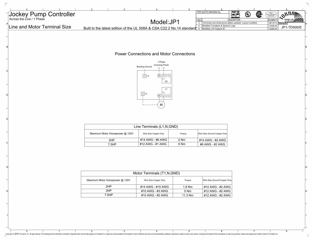
JP1-TD500/EModel
Line and Motor Terminal Size:JP1
NYCDpt of Building
Approved
Drawing No.
DD/MM/YYDESCRIPTION
PER QUOTE DRAWING No.
REV.Across the Line / 1 Phase
Built to the latest edition of the UL 508A & CSA C22.2 No.14 standard
Jockey Pump ControllerDrawing No.
Line Terminals (L1,N,GND)
Maximum Motor Horsepower @ 120V Wire Size Copper Only Torque
Motor Terminals (T1,N,GND)
Wire Size Copper Only Torque
Wire Size Ground Copper Only
Wire Size Ground Copper Only
2HP #14 AWG - #6 AWG 2 Nm7.5HP #12 AWG - #1 AWG 6 Nm
2HP #14 AWG - #10 AWG 1.8 Nm3HP #10 AWG - #3 AWG 5 Nm
7.5HP #10 AWG - #2 AWG 11.3 Nm
#14 AWG - #2 AWG#6 AWG - #2 AWG
#14 AWG - #2 AWG#12 AWG - #2 AWG#12 AWG - #2 AWG
Maximum Motor Horsepower @ 120V
Bonding GroundIncoming Power
Power Connections and Motor Connections
M
T1
C1
L1DS
N
N
1 Phase
3 4 5 6 72
G
H
0 1 8
B
C
D
E
F
I
A
3 4 5 6 720 1 8
G
H
I
A
B
C
D
E
F
2016Copyright © Tornatech Inc. All right reserved. This drawing and the information contained or depicted herein are the sole property of Tornatech Inc. Copies are communicated to the recipient in strict confidence and may not be retransmitted, published, reproduced, copied or used in any manner, including as the basis for the manufacture or sale of any products, without the express prior written consent of Tornatech Inc.
4 Terminals and dimensions tables updated. Layout modified. 09/10/155 Modified Tornatech & Seismic Logo 14/04/166 Modified J19 Outputs ID 10/06/16