Embed Size (px)
Citation preview

Contents
Section I – Introduction ...........................................................................................................................................1Section II – Connecting via Ethernet .....................................................................................................................2 Configuring the AccuLoad.net for Ethernet Communications .............................................................................2 Configuring Windows 2000/XP for Ethernet Connection to AccuLoad.net ..........................................................3Section III – Configuring a SLIP Connection ........................................................................................................5 AccuLoad Settings for SLIP Communications .....................................................................................................5 PC Settings for SLIP Communications ................................................................................................................6Section IV – Using the TCP/IP Link ........................................................................................................................8 Checking the TCP/IP Connection ........................................................................................................................8Section V – Firmware Upgrade Procedure ............................................................................................................9 Upgrading the Firmware with the AccuLoad.net .................................................................................................9 Procedure for Upgrading Firmware .....................................................................................................................9 Troubleshooting .................................................................................................................................................13Appendix – Troubleshooting TCP/IP Communications ......................................................................................14 Troubleshooting an Ethernet Connection ..........................................................................................................14 Troubleshooting a SLIP Connection ..................................................................................................................14
Issue/Rev. 0.2 (6/14) Bulletin AB06069
The Most Trusted Name In Measurement
Application Manual
TCP/IP (Ethernet & Slip) Communications and Upgrading Firmware
Smith Meter® AccuLoad® III.net

Caution
The default or operating values used in this manual and in the program of the AccuLoad.net are for factory testing only and should not be construed as default or operating values for your metering system. Each metering system is unique and each program parameter must be reviewed and programmed for that specific metering system application.
Disclaimer
FMC Technologies Measurement Solutions, Inc. hereby disclaims any and all responsibility for damages, including but not limited to consequential damages, arising out of or related to the inputting of incorrect or improper program or default values entered in connection with the Smith Meter® AccuLoad® III.net.
Proprietary Notice
This document contains information that is proprietary to FMC Technologies Measurement Solutions, Inc. and is available solely for customer information. The information herein shall not be duplicated, used, or disclosed without prior permission of FMC Technologies Measurement Solutions.FMC Technologies Measurement Solutions, Inc. will not be held responsible for loss of liquid or for damage of any kind or from any cause to the person or property of others, or for loss or profit, or loss of use, or any other special, incidental, or consequential damages caused by the use or misapplication of the contents stated herein.

Issue/Rev. 0.2 (6/14) AB06069 • Page 1
Section I – Introduction
Introduction to TCP/IP Communications and Basic Networking
It is not necessary to become a skilled network administrator to successfully communicate with the AccuLoad.net via TCP/IP. However, some basic networking knowledge will be quite helpful in establishing and maintaining reliable communications with devices such as the AccuLoad.net that can be connected via Ethernet and TCP/IP. Some of the following terms may be encountered while configuring or maintaining your device connections: TCP/IP (Transfer Control Protocol/Internet Protocol) is the widely accepted standard protocol for Internet and World Wide Web communications. Many other Internet standard protocols – HTTP for Web browsing, FTP for file transfers, etc. – use TCP/IP as the underlying control protocol. Ethernet: A low-level protocol that implements the hardware link between two or more host devices. TCP/IP is often used over an Ethernet connection. MAC Address: A fixed, permanent 6-byte hardware address assigned to an Ethernet device by the manufacturer. IP Address: a four-byte (32 bit) number, usually displayed as 4 separate octets (8 bit numbers) i.e. 192.168.0.1, that uniquely identifies a host and network. IP address ranges are grouped by class; the first few bits determine the class. Class ‘A’ networks have a value from 0-127 in the first octet; class ‘B’ networks start with 128-191; class ‘C’ from 192-223. The special values of 224-239 are reserved for class ‘D’ (multicast) addresses, and the values 244-255 are reserved (class ‘E’) addresses. Net Mask: The number of bits in the IP address that are used to specify the network address. The remaining bits specify the host address. A Class ‘C’ network has a net mask of 24 (the first 24 bits are common to all machines on the network, the last 8 bits are the host id and are unique for each machine on the network). Therefore, a class ‘C’ network can have up to 254 hosts (host numbers 0 and 255 are reserved by the standard for special features such as broadcasting.) A very large class ‘A’ network has an 8 bit net mask – leaving 24 bits to specify the host. Hence this type of network can have a huge number of host machines 224 = over 16 million computers – but there can only be 255 of those types of networks in existence since there are only 255 unique network IDs that can be made from 8 bits. So why specify a net mask if it’s implied by the network class? The reason for a net mask is clear when it is realized that some networks need to have many more hosts than 255, and that there would not be very many networks if we only allowed Class ‘A’ networks. Net masks are often written out in octet form… 255.255.255.0 is the same as saying the net mask is 24 bits. It can also be specified with the network address using a backslash, i.e. 192.168.0.0/24. So, if we have a machine on that network with the IP address 192.168.0.23 (A class ‘C’ network), the network address is 192.168.0 and the host address is 23. There are some network addresses that are reserved by the standard as ‘local network’ addresses. These network addresses are allowed only behind a router that ‘hides’ the local network from the Internet. Many internal internet networks use these addresses: all the class ‘C’ networks starting with 192.168.xxx.xxx/24 and the class ‘A’ network 10.xxx.xxx.xxx/8. Since most organizations do not require a full class ‘A’ network, often a subsection of the address space is used, i.e. 10.0.xxx..xxx/16. This is called ‘sub-netting’. Alternatively, sometimes two or more class ‘C’ networks are combined thus: 192.168.0.xxx/23. This is known as ‘super-netting’. Gateway: a gateway address specifies where outgoing messages addressed to other networks should be directed. This allows devices like routers, hubs and switches to be specified as the interface to anything external to the physical network.
Information on TCP/IP and networking can be found on the World Wide Web. One example of a more detailed description can be found at http://www.faqs.org/rfcs/rfc1180.html. This is one of an entire series of RFCs (Request For Comments) that make up the documentation on networking standards.

Issue/Rev. 0.2 (6/14)Page 2 • AB06069
Automation Host
Hub
Corporate PC
Ethernet
Firewall
Internet
Printer
Corporate PC
Section II – Connecting via Ethernet
Configuring the AccuLoad.net for Ethernet Communications • Power up the AccuLoad (wait for AccuLoad to complete initialization) • Press <Enter> at the Ready screen to access the Main Menu • From the Main Menu, select Program Mode Menu and press <Enter> • Enter the Access Code when prompted and press <Enter> • From the Program Mode menu, select System Directory then Press <Enter> • From the System Directory, select 700 Communications Directory • Select Host Interface and press <Enter> • From the Host Interface Menu set the following items:
IP Address: 192.168.0.1 Net mask: 255.255.255.0 Gateway: 192.168.0.10 Ethernet Control: Poll and Program Comm Link: Level 3
• Return to the Main Menu using the <Clear> key
Note: If using the AccuLoad.net’s Ethernet port, make sure that none of the AccuLoad.net serial communications ports are configured to the ‘SLIP (TCP/IP)’ function – configuring a SLIP connection will disable the Ethernet connection.
It is recommended that the AccuLoad.net be installed to a private network (not connected directly to the rest of the corporate LAN). This is best implemented by adding a second network interface card to the PC that will be interfaced to the AccuLoads. This dual-interface PC can be set up as a ‘bridge’ allowing all the other PCs in the corporate environment to reach the AccuLoad devices (given permission to do so) but will prevent all other corporate LAN traffic from interfering with the AccuLoad.net communications.
Issue/Rev. 0.2 (6/14) AB06069 • Page 3
Section II – Connecting via Ethernet
Configuring Windows 2000/XP for Ethernet Connection to AccuLoad.netRequirements: • A Network Interface Card (NIC) installed in the PC and either: – a CAT-5 ‘crossover’ cable; or alternately – two regular CAT-5 cables, and an Ethernet hub/switch/router such as those manufactured by D-Link, LINKSYS, 3Com, et. al.
Your PC has a NIC interface if there is an Ethernet port (CAT-5 connector) present on the back of the computer. Most modern PCs have the Ethernet hardware integrated on the motherboard. Typically these ports are labeled with a network icon: . If there is no Ethernet hardware in your PC you can add one – they are relatively inexpensive and easy to install. Another option is to use a SLIP connection (see Configuring SLIP Communications).
There are two ways to connect the AccuLoad to your PC using Ethernet – either machine-to-machine, using a cross-over cable; or connecting both the PC and the AccuLoad to a multi-port network device such as a hub, switch or router.
If using a crossover cable, plug one end of the cable into the Ethernet port on the PC. If using a hub, connect the PC’s Ethernet port to one of the router’s ports using a standard cable.
At the AccuLoad.net, remove the cover and find the CAT-5 connector (CN16) on the KDC board (the main board, attached to the cover). Plug the other end of the crossover cable in here, or if using a hub connect the second standard CAT-5 cable between the AccuLoad.net and another port on the hub. The AccuLoad has two LEDs near CN16 – the green LED will light if the physical connection is established properly. The yellow LED will blink when traffic appears on the network.
Note: If the system is currently on a network, be sure to record all values prior to changing the connection settings so the network connection can be restored to the original state.
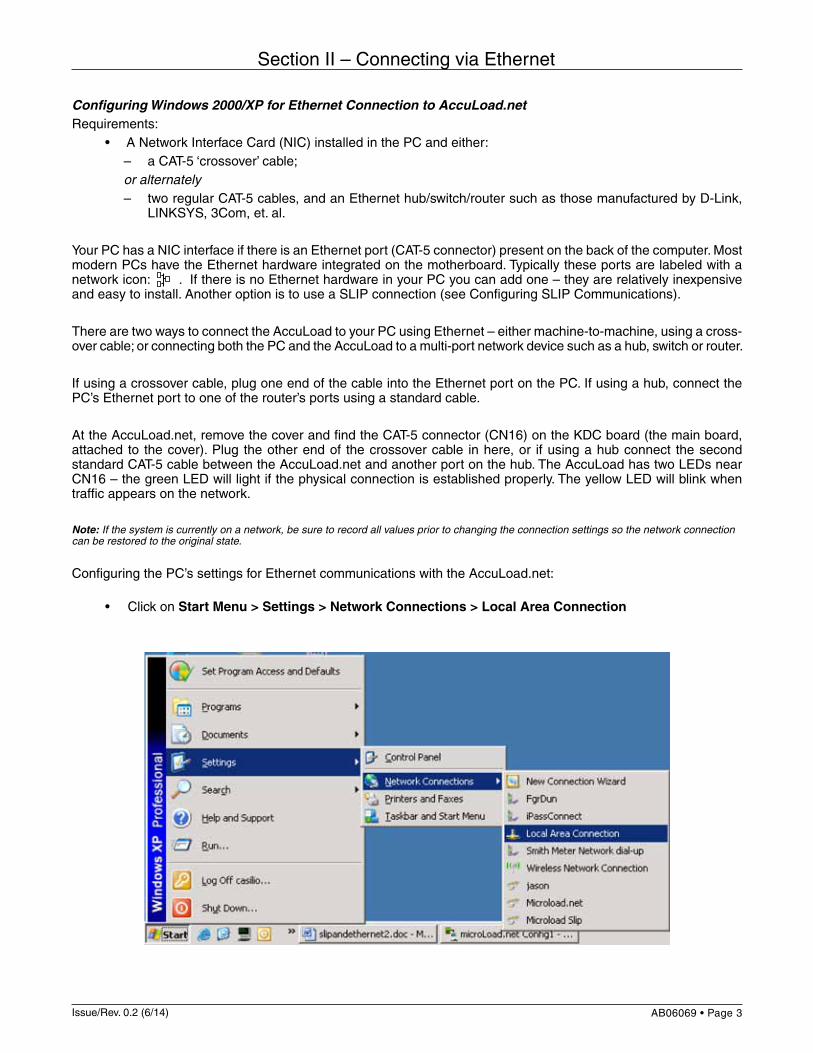
Configuring the PC’s settings for Ethernet communications with the AccuLoad.net: • Click on Start Menu > Settings > Network Connections > Local Area Connection

Issue/Rev. 0.2 (6/14)Page 4 • AB06069
Section II – Connecting via Ethernet
Uncheck all of the boxes EXCEPT the check box for “Internet Protocol (TCP/IP)” Make sure that the “Internet Protocol (TCP/IP)” line is selected then click ‘Properties’
Select “Use the following IP address” Enter an IP address on the same network as the AccuLoad, i.e. 192.168.0.10 (Make sure the host address is different than the AccuLoad.net!) Enter the subnet mask: 255.255.255.0 Click OK when finished
Click OK again to exit the Local Area Connection dialog
To check the communication link, see Section IV – Using the TCP/IP Link.
u

Issue/Rev. 0.2 (6/14) AB06069 • Page 5
Section III – Configuring a SLIP Connection
Configuring SLIP Communications (Available with Windows 2000/XP Only)
If an Ethernet connection is not available or distances prevent the use of Ethernet, the AccuLoad.net can also support TCP/IP communications over one of the serial ports. This is implemented via SLIP (Serial Line Internet Protocol) support in the AccuLoad.net.
Note: Skip this section if using Ethernet. Continue with the section titled Establishing and Verifying a Successful Connection (located in Section IV).
Remove cover and connect the AccuLoad communications port to the PC serial port using a serial communications line. (AccuLoad.net Comm 1 is used in the example.) Wire the serial connection as for any other serial protocol. (For instructions on connecting the AccuLoad to the PC via serial communications please refer to the installation manual for the AccuLoad.)
AccuLoad.net Settings for SLIP Communications • Power up the AccuLoad.net (wait for AccuLoad to go through its initialization period ie. RAM and ROM test) • Press <Enter> from the ready screen to access the Main Menu • Once in the Main Menu screen, select Program Mode Menu and press <Enter> • Enter the access code when prompted and press <Enter> • Select System Directory then press <Enter> • Select Comm. Directory and press <Enter> • From Comm. Directory, select Comm. Port Config and press <Enter> • Select Comm. 1 and press <Enter> • From Comm. 1 Directory, select the following items and set as indicated below: Function: SLIP (TCP/IP) Baud: 38,400 Data Parity: 8/None Timeout: 0 Mode: RS232 • After ALL items from above are set, press <Clear> twice to return to the Communications Directory Menu • Select Host Interface and press <Enter> • From the Host Interface Menu set the following items as indicated below: IP Address: 192.168.0.1 Network: 255.255.255.0 Gateway: 192.168.0.1 Ethernet Control: Poll and Program Comm Link: Level 1
Note: SLIP is a point to point protocol and is not intended for multi-dropped serial networks. It is possible to utilize a SLIP connection in a multi-drop environment for special features such as firmware upgrades, but any additional AccuLoad III.net devices on the communications line must have the serial port functionality disabled before attempting to connect to any one unit.

Issue/Rev. 0.2 (6/14)Page 6 • AB06069
Section III – Configuring a SLIP Connection
PC Settings for SLIP Communications • Click on Start > Settings > Network Connections > New Connection Wizard:
• In the New Connection Wizard, perform the following steps: – Select <Next> on the “Welcome to the New Connection Wizard” page) – Select “Set up an Advanced Connection”, from the list then click <Next> – Select “Connect directly with another computer”, then click <Next> – Select “Guest”, then click <Next> – In the text box, type in “AccuLoad via SLIP” or something identifiably unique – Select “Communications cable between two computers (Com 1)” when the wizard prompts for a device selected. Click <Next> – Click on “Anyone’s Use” for connection availability. Click <Next> – Click <Finish> on the Confirmation page of the Wizard • Upon completion, a new screen will pop up automatically with the title “Connect to AccuLoad via SLIP” • Click <Properties> – In the General tab, select “Communications cable between two computers (COM n)”. Verify the selection corresponds to the desired port. – Click on the <Configure> button located on the same screen (below the selected device). Set the baud rate to 38400. In the hardware features verify that all boxes are unchecked. Click <OK> to return to the Properties dialog.

Issue/Rev. 0.2 (6/14) AB06069 • Page 7
Section III – Configuring a SLIP Connection
• Click on the Options tab. Uncheck the “Prompt for name and password, etc.” box. The other options can be left the same.
• Click on the Networking tab. – From the drop down menu for the type of dial up server I am calling, select “SLIP: UNIX Connection” – Clear all checkboxes except for Internet Protocol (TCP/IP) and QoS Packet Scheduler. – Select “Internet Protocol (TCP/IP) ” in the list box and click <Properties>
• A new window will appear that is labeled “Internet Protocol (TCP/IP) Properties” – Select “Use the following IP address” – Specify an address that is DIFFERENT from but on the same subnet as the AccuLoad you are using
For example, if the AccuLoad is configured for 192.168.0.1, set the PC to 192.168.0.5, or 192.168.0.10, etc.
Click <OK> to exit the dialog then click <OK> at the bottom of the AccuLoad SLIP Connection Properties window. If all is configured correctly, the dialog should report ‘connected’ and the link will be established successfully.

Issue/Rev. 0.2 (6/14)Page 8 • AB06069
Section IV – Using the TCP/IP Link
Using the TCP/IP Link
Checking the TCP/IP ConnectionInstall the latest version of the AccuMate.net software. This can be found on the World Wide Web – go to http://fmctechnologies.com/measurementsolutions and select the "Literature, Videos & Software" icon. It is recom-mended that the installation defaults be used, resulting in the program being installed to the directory C:\Program Files\Smith Meter\AccuMate for AccuLoadIII.net.
Establishing and Verifying a Successful ConnectionAfter installation, perform the following steps to check the connection you established:
• Launch the AccuMate application from the Start menu • Select Options | Options for this AccuLoad from the AccuMate menu. • Enter the IP address you programmed into the AccuLoad III.net (i.e. 192.168.0.1) • In the ‘Port’ combo box, choose TCP/IP. (This selection is at the top, above Com 1) • Click “OK”. If communications is established, the status bar at the bottom of the AccuMate window should indicate a successful connection with the word “ONLINE”. (Note: the status may appear as “Read Only”, which also indicates the connection was successful; this will occur if the AccuLoad III.net is in program mode via the keypad, or configured so that Program Mode access through communications is disabled.)
With the AccuMate you can read and write program codes, use the Terminal Emulator to send any of the available commands to the AccuLoad, read transaction and event logs, and upload special features like user configured re-ports, displays, translations, and equations. See the online help file for the AccuMate application for help on utilizing all of the AccuMate features.
Also available via the TCP/IP link is a Web (http) interface. By launching your browser and entering the IP address of the AccuLoad III.net for a URL (i.e. http://192.168.0.1), you can access this interface.
In addition, the AccuLoad III.net has built-in FTP support. This is the protocol used to transfer new Firmware (.bin) files for Firmware upgrades. The HTML pages are included in Firmware. The FTP implementation is complete enough to work satisfactorily with a command line FTP utility. Configurations, items, equations, and translations are transferred using TCP/IP protocol.

Issue/Rev. 0.2 (6/14) AB06069 • Page 9
Section V – Firmware Upgrade Procedure
AccuLoad III.net Firmware Upgrade Procedure
OverviewThe AccuLoad III.net has Flash based internal non-volatile memory to store and execute the firmware; this allows the firmware to be upgraded without replacing EPROMs as in the past. The new firmware will be downloaded to the AccuLoad from AccuMate using TCP/IP. Either the Ethernet communications port or a SLIP serial port (TCP/IP over serial) may be used for the transfer. Firmware Revision Upgrade KeyTo upgrade a board with a new revision of software, a factory supplied key will be required. This key will have the following information encoded in it: • MAC address for board being upgraded • Revision of firmware to be installed • Current number of arms • New number of arms
When a firmware upgrade is required, the factory must be supplied with either the current key for each board or the MAC address, current revision, and current number of arms allowed for the board(s) being upgraded. A unique key is required for each board. This key will give the ability to upgrade the firmware to the new revision. A new key will also be required if the upgrade is to increase the maximum number of arms only.Each key will only be valid for a unique KDC.net board and also for a specific revision of firmware. It will be the re-sponsibility of the customers to save these keys in case the firmware needs to be reloaded with the same revision of firmware at a future time.AccuMate will prompt for the key prior to upgrading the firmware. The AccuLoad will decode the key and if the MAC address doesn't match the actual MAC address of the board, the new firmware will be rejected. Also if the current number of arms doesn't match what the board actually has, the firmware will be rejected. If the key is valid, the AccuLoad will allow the upgrade to proceed and will also update the maximum number of arms allowed.The AccuLoad provides a diagnostic to display the current key used (Diagnostics/AccuLoad Information). The customer should record this value in case they would need to re-install the same firmware version at a future time. Procedure for Upgrading FirmwareNote: Prior to upgrading the firmware, be sure to backup and save all configurable files such as the .A3X data file, Equations, Reports,Translations and Driver Databases. 1. The key and .bin file should be placed in the same directory where the AccuMate Application program resides. The default directory for AccuMate is C:/Program Files/Smith Meter/AccuMate for AccuLoad III.net. 2. The communications link parameter (System 731) must be at highest security level otherwise the AccuLoad will not allow the firmware to be upgraded. 3. Open AccuMate.net and open a data file (with .a3x file extension). 4. Go to Tools on the menu bar, and click on Upgrade Firmware. See Figure 1. Upgrade cannot be accomplished until AccuMate is online and connected to the AccuLoad. 5. Isolate the ethernet port and all other serial ports from any other activity before performing the upgrade.

Issue/Rev. 0.2 (6/14)Page 10 • AB06069
Section V – Firmware Upgrade Procedure
Figure 1
Figure 2
6. Click OK on the dialog box shown in Figure 2.
Issue/Rev. 0.2 (6/14) AB06069 • Page 11
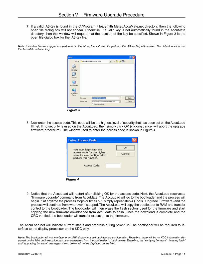
7. If a valid .A3Key is found in the C:/Program Files/Smith Meter/AccuMate.net directory, then the following open file dialog box will not appear. Otherwise, if a valid key is not automatically found in the AccuMate directory, then this window will require that the location of the key be specified. Shown in Figure 3 is the open file dialog box for the .A3Key file.
Note: If another firmware upgrade is performed in the future, the last used file path (for the .A3Key file) will be used. The default location is in the AccuMate.net directory.
8. Now enter the access code. This code will be the highest level of security that has been set on the AccuLoad III.net. If no security is used on the AccuLoad, then simply click OK (clicking cancel will abort the upgrade firmware procedure). The window used to enter the access code is shown in Figure 4.
9. Notice that the AccuLoad will restart after clicking OK for the access code. Next, the AccuLoad receives a "firmware upgrade" command from AccuMate. The AccuLoad will go to the bootloader and the process will begin. If at anytime the process stops or times out, simply repeat step 4 (Tools | Upgrade Firmware) and the process will continue from wherever it stopped. The AccuLoad will copy the bootloader to RAM and transfer control to the bootloader. The bootloader will then erase the flash sectors used for the firmware and start copying the new firmware downloaded from AccuMate to flash. Once the download is complete and the CRC verified, the bootloader will transfer execution to the firmware.
The AccuLoad.net will indicate current status and progress during power up. The bootloader will be required to in-terface to the display processor on the KDC only.
Note: The bootloader will not interface to an MMI display in a split architecture configuration. Therefore, there will be no KDC information dis-played on the MMI until execution has been transferred from the bootloader to the firmware. Therefore, the "verifying firmware", "erasing flash" and "upgrading firmware" messages shown below will not be displayed on the MMI.
Section V – Firmware Upgrade Procedure
Figure 3
Figure 4

Issue/Rev. 0.2 (6/14)Page 12 • AB06069
Section V – Firmware Upgrade Procedure
If the bootloader is waiting for firmware from AccuMate the AccuLoad will display the following message. The message displayed will change to indicate the current task being performed, for example, “erasing flash” followed by “upgrading firmware”. The bar graph will indicate progress made while performing the current task.
If a firmware image has already been downloaded, the bootloader will display the following message on power up:
After the firmware has been verified, execution is transferred to the firmware and the RAM is verified.
MAC 00:05:C2:1E:74:03
Waiting for firmware upgrade
Verifying firmwarePlease Wait
FMCAccuLoad.netRAM Test . . .

Issue/Rev. 0.2 (6/14) AB06069 • Page 13
Section V – Firmware Upgrade Procedure
Troubleshooting Tips • Make sure that AccuMate is first upgraded to the new AccuMate version. For example, if revision 11.01
firmware is being loaded, then AccuMate.net 11.01 should be installed on the PC. Otherwise the upgrade will not work.
• If the wrong key is loaded, then the upgrade firmware process will not even begin. In this case, you must obtain the correct key.
• If the following message is received when trying to execute a Firmware Upgrade:
- Verify under "Options for this AccuLoad III" that the Com/Port and IP address are properly set for the AccuLoad that the upgrade is being applied to. - Verify that the communication settings on the computer being used for performing the upgrade are set properly as described on pages 3 and 4 ("Configuring Windows 2000/XP for ethernet connection to AccuLoad") or on pages 6 and 7 ("PC Settings for SLIP Communications"). - Isolate the ethernet port and all other serial ports from any other activity before performing the upgrade.
Troubleshooting the Firmware Upgrade Process; Consult Factory Service When the AccuLoad restarts (after the firmware upgrade process has completed) if a message is displayed stat-ing that the "Expected CRC Failed" this means that the firmware did not completely load. In this case, the firmware upgrade procedure must be restarted.It may be necessary to use the following switch settings when consulting with factory service to correct this type of issue:
Switch SettingsAn 8 pin DIP switch resides on the KDC.net board (SW1-SW8). The switch will be utilized as follows:
SW1 – Force Firmware Upgrade (on power up Bootloader waits for firmware upgrade). For factory use only.SW2 OFF – SW3 OFF, the Bootloader uses previously programmed IP address (default)SW2 ON – SW3 OFF, Bootloader uses IP address 192.168.0.1SW2 OFF – SW3 ON, Bootloader uses IP address 10.0.0.1SW2 ON – SW3 ON, Bootloader uses DHCP to determine address

Issue/Rev. 0.2 (6/14)Page 14 • AB06069
Appendix – Troubleshooting TCP/IP Communications
Appendix I – Troubleshooting TCP/IP Communications
Troubleshooting an Ethernet Connection • LED Indicators The Link indicator on the Ethernet port (the green LED in top corner of AccuLoad.net main [KDC.NET] board) is a simple indication of the correct wiring of the physical connection. Most PC and router ports also have a visible indicator when the connection is wired properly. If the Link light does not illuminate, either the cable is the wrong type (i.e. a standard CAT-5 cable was used when a crossover cable is needed or vice versa), the cable is faulty, or one of the RJ45 connector plugs is not inserted completely into the jack. It is also possible but unlikely that one of the device ports has failed. Eliminate the simplest first: double-check that the plugs are inserted fully; and that the cable type is correct. You can often verify that a cable is standard (or not) by holding the two connectors from each end of the cable together and viewing the wire colors within (most RJ45 connectors are clear plastic). If the color pattern on the wires is identical on both ends of the cable, it is a standard cable.
• PING Utility To check the connection, Windows and most other networkable computers provide a low-level utility called PING that issues a simple ICMP message to a remote device and awaits a response. To use this utility in Windows, open a Command Prompt (DOS box) and type the command: C:> PING ["UNIT ADDRESS"]
C:> PING 192.168.0.1
If the connection is successful, PING will report the total time from command to response. If it fails, a timeout message will be displayed.
• Advanced – Ethernet Diagnostic (Packet Sniffer) Utility A useful tool for troubleshooting network communications is a packet sniffer. This type of utility provides a mechanism to display the traffic being sent/received from the Ethernet port, and to dig down to the lower levels to view MAC addresses and IP packet data.
An open source implementation of a packet sniffer utility, Wireshark (formerly Ethereal), is available and can be downloaded from the Web at http://www.wireshark.org/. There are versions for Windows, Linux and other platforms as well.
Troubleshooting a SLIP Connection • Using the Comm Monitor Diagnostic The AccuLoad.net has a built-in diagnostic that displays traffic on the serial communications ports. To access the Comm Monitor diagnostic, select Diagnostics Menu from the Main Menu, then scroll using the arrow keys until the Comm Monitor selection is highlighted and press <Enter>. Then select the communications port (1-3) that was configured for the SLIP connection. By examining the traffic it is possible to determine if data is being received from the PC end, and whether a response is being issued. You can ‘freeze’ the display, and scroll back and forth, and toggle ASCII and hex mode views of the last 255 characters in the communications buffer.
• CLIENT/CLIENTSERVER Handshake When establishing a SLIP connection between two devices, Windows uses a non-standard handshake to verify the device on the other end of the connection is compatible. Windows opens the port and immediately sends the text “CLIENT” out the port, then waits for a response. Only the response “CLIENTSERVER” will be accepted by Windows and allow the connection to be made. This handshake should happen quickly and it will be visible on the Comm Monitor at least briefly if all is functioning properly. If the Comm Monitor shows repeated CLIENT messages with no CLIENTSERVER response, it is possible you have the IP addresses incorrect on one side or the other. The host PC’s IP address should be different than the AccuLoad.net, but again both addresses must be on the same network.
Example: Where unit address is the IP Address of ALIII.

Issue/Rev. 0.2 (6/14) AB06069 • Page 15
Appendix I – Troubleshooting TCP/IP Communications
• Checking the PC Serial Port Settings If viewing the Comm Monitor diagnostic and there appears to be data arriving at the AccuLoad but it seems illegible or garbled, perhaps there is a mismatch in the baud rate/parity settings. You can verify the port settings by examining the properties in the SLIP connection settings. You can also check them via the command line. Shut down the SLIP connection, then from a command prompt, type the following command: C:> MODE COM1:
This command will display the current port settings for the COM port specified. You can also modify the port settings using this command: C:> MODE COM1:38400,N,8,1
This utility may be useful for troubleshooting AccuMate serial communications as well.

Revisions included in AB06069 Issue/Rev. 0.2 (6/14): Page 9: Item 5 added to "Procedure for Upgrading Firmware" and revised wording on item 4. Page 13: Total revision to this page; "Switch Settings" moved from page 12 to 13..
Printed in U.S.A. © 6/14 FMC Technologies Measurement Solutions, Inc. All rights reserved. AB06069 Issue/Rev. 0.2 (6/14)
www.fmctechnologies.com/measurementsolutions
The specifications contained herein are subject to change without notice and any user of said specifications should verify from the manufacturer that the specifications are currently in effect. Otherwise, the manufacturer assumes no responsibility for the use of specifications which may have been changed and are no longer in effect.
Contact information is subject to change. For the most current contact information, visit our website at www.fmctechnologies.com/measurementsolutions and click on the “Contact Us” link in the left-hand column.
Headquarters:500 North Sam Houston Parkway West, Suite 100, Houston, TX 77067 USA Phone: +1 (281) 260 2190 Fax: +1 (281) 260 2191
Ellerbek, Germany +49 (4101) 3040Erie, PA USA +1 (814) 898 5000
Integrated Measurement Systems:Corpus Christi, TX USA +1 (361) 289 3400Kongsberg, Norway +47 (32) 286700
Operations: Measurement Products and Equipment: