Embed Size (px)
Citation preview

Revision 03, May 2005© Copyright 2005 RapidIO® Trade Association
���������������� ����� �
�������® ��� � ���������������������� ��
Technical Discussion of the RapidIO Interconnect and System Design Examples

© Copyright 2005 RapidIO® Trade Association Slide 2Revision 03
Embedded Systems Driving Standard Interconnect Requirements
Development Needs• Higher performance• Lower system costs
(NRE, CAPEX, OPEX)• Modularity – reuse across
platforms• Common components• Distributed processing• Standardized connectivity
Standard Interconnect Requirements• High-performance• Multiple hosts – distributed
processing• Direct peer-to-peer communications• Multiple heterogeneous operating
systems• DMA and message passing• Support complex topologies
– Discovery mechanism– Redundant paths – fail over
• Multicast• High Reliability
– Loss less– Automatic retraining and device
synchronization– System level error management
• Time of day synchronization• Quality of Service (QoS)
© Copyright 2005 RapidIO® Trade Association Slide 3Revision 03
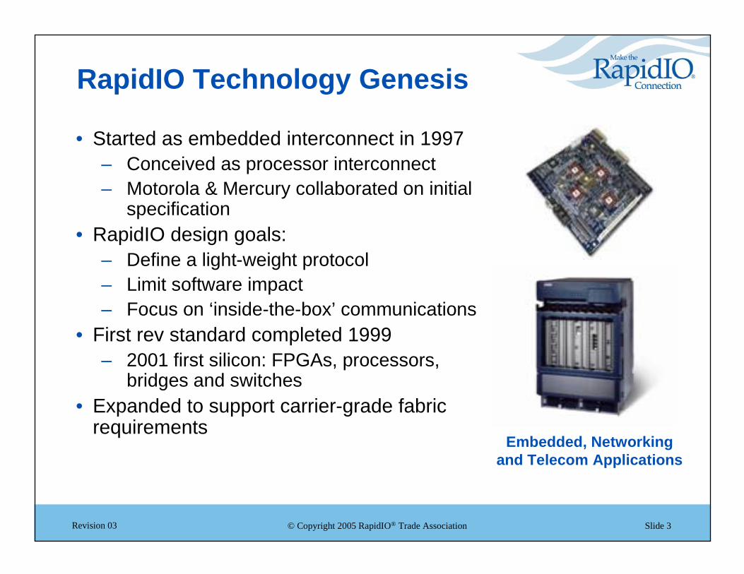
RapidIO Technology Genesis
• Started as embedded interconnect in 1997– Conceived as processor interconnect– Motorola & Mercury collaborated on initial
specification• RapidIO design goals:
– Define a light-weight protocol– Limit software impact– Focus on ‘inside-the-box’ communications
• First rev standard completed 1999– 2001 first silicon: FPGAs, processors,
bridges and switches• Expanded to support carrier-grade fabric
requirementsEmbedded, Networking
and Telecom Applications

© Copyright 2005 RapidIO® Trade Association Slide 4Revision 03
RapidIO Technology System Value
• Scalable, modular architecture– Layered architecture with
common transport layer– Chip-to-chip, board-to-board,
backplane• High-speed connectivity
– Physical layer defined for backplane interconnection
• ~80-100 cm + 2 connectors (Serial)
– Up to 10Gbps bandwidth today• Robust feature set
– Carrier-grade reliability– Traffic management– Multi-protocol/convergence
Memory
SwitchSwitch
HostProcessor
HostProcessor
ProcessorProcessor
Memory
ProcessorProcessor
Memory
HostProcessor
HostProcessor
Memory
ProcessorProcessor
Memory
ProcessorProcessor
Memory
SwitchesSwitches

© Copyright 2005 RapidIO® Trade Association Slide 5Revision 03
RapidIO Architecture
8,16Parallel
Logical Specifications
Transport Specifications
Physical Specifications
Global SharedMemory
Message Passing
I/O System
Higher SpeedPHYs
FlowControl
Common Transport
1x/4x Serial
DataStreaming
Ancillary Specifications MulticastInteroperability Error
ManagementSystemBring up

© Copyright 2005 RapidIO® Trade Association Slide 6Revision 03
Physical Layer Specifications
• Parallel– 8/16b LVDS– 250 MHz to 1 GHz DDR
• Serial– 1 or 4 lane XAUI AC coupled– 8/10b encoded– 1.25 / 2.5 / 3.125 Gbaud– Aggregated bandwidth of up to 10Gbps in a x4 sRIO link
• Point-to-point topology• Device synchronization and training• Every packet is acknowledged or retried (16 or 32b CRC
applied)• Explicit hardware-based error recovery• Control symbols provide the main mechanism for physical
layer control (can be embedded within packets)• Four fixed priorities
– Mechanism for higher and lower priority traffic– Order is maintained for traffic at a given priority– Transaction acknowledge/reply higher priority than
request• Link-level flow control
Logical Specifications
Transport Specifications
Physical Specifications
Ancillary Specifications
8,16Parallel
1x/4xSerial

© Copyright 2005 RapidIO® Trade Association Slide 7Revision 03
Transport Specification
• Switches operate at the transport layer– All logical protocols use a common transport header– Today’s switches will work with future logical
protocols• Device-based routing
– 8 or 16 bit device ID• Simplifies classification and routing compared to
Ethernet or IP– Any RapidIO device ID can be used as a unicast ID
or a multicast group• Unicast packets are forwarded out a single port• Multicast packets are elaborated to multiple ports at
the switch connected to leaf nodes• Can multicast using a transaction that omits a logical
layer acknowledge, i.e., NWRITE, SWRITE, Data Streaming
– Fail-over events only affect routing table entries of nearest neighbors
• Unlike path based routing architectures
Logical Specifications
Transport Specifications
Physical Specifications
Ancillary Specifications
CommonTransport
Multicast

© Copyright 2005 RapidIO® Trade Association Slide 8Revision 03
Input/Output Logical Specification
• Load / Store / DMA operations– Processor is not necessarily RapidIO aware
• 34, 50, 66-bit address space• Transactions:
– NREAD – read operation• Data returned is the response
– NWRITE – write operation, no response– NWRITE_R – robust write with response from
the target end-point– SWRITE – streaming write– ATOMIC – atomic read-modify-write– MAINTENANCE – system discovery,
exploration, initialization, configuration and maintenance operations
Logical Specifications
Transport Specifications
Physical Specifications
Ancillary Specifications
I/OSystem

© Copyright 2005 RapidIO® Trade Association Slide 9Revision 03
Message Passing Logical Specification
• Hardware support for segmentation and reassembly of 4kB datagrams– Segments are automatically reordered
• Logical Layer acknowledge– Auto retry on timeout
• Messages– Organized into 4 mailboxes and 4 letters within
each mailbox• Sending device can send 4 concurrent letters to
each target mailbox
• Doorbells– Short 8 or 16-bit messages
Logical Specifications
Transport Specifications
Physical Specifications
Ancillary Specifications
MessagePassing

© Copyright 2005 RapidIO® Trade Association Slide 10Revision 03
Data Streaming Logical Specification
• Segmentation and reassembly– 64Kb PDUs– System-wide MTU size
• Efficient logical protocol for communications– Start, continuation, end segments
• continuation has 20 bit header
• Interworking– Ethernet, UTOPIA, SPI-3/4, CSIX, etc
• Virtual Streams– Flow identification
• Traffic Management framework– End-to-end Flow control– Millions of streams– 256 traffic classes – Lossy operations
• No logical layer acknowledge to support traffic managed data plane applications
Logical Specifications
Transport Specifications
Physical Specifications
Ancillary Specifications
DataStreaming

© Copyright 2005 RapidIO® Trade Association Slide 11Revision 03
Other Features
• Specification includes a user-defined logical protocol for custom extensions
• Packets are 256 payload bytes or less• Ancillary Specifications
– Interoperability• PCI transaction mapping• Hardware Interoperability Platform (HIP)• Interoperability checklist
– Error Management
– System Bring-up
© Copyright 2005 RapidIO® Trade Association Slide 12Revision 03
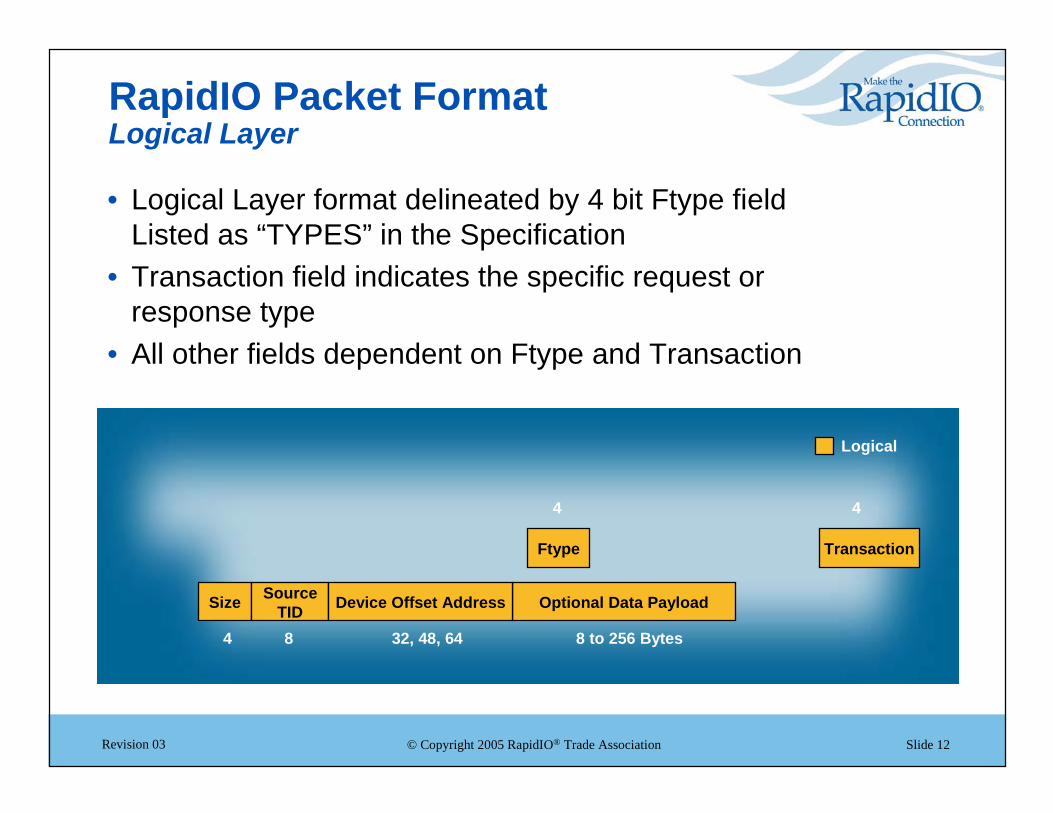
RapidIO Packet FormatLogical Layer
• Logical Layer format delineated by 4 bit Ftype fieldListed as “TYPES” in the Specification
• Transaction field indicates the specific request or response type
• All other fields dependent on Ftype and Transaction
8 to 256 Bytes
4 4
84 32, 48, 64
Optional Data Payload
Ftype
Size SourceTID
Transaction
Device Offset Address
Logical

© Copyright 2005 RapidIO® Trade Association Slide 13Revision 03
RapidIO Packet Format TYPES
• I/O non-coherent functions– NREAD, NWRITE, NWRITE_R, SWRITE, ATOMIC
• Message functions– DOORBELL, MESSAGE
• System support functions– MAINTENANCE
• Flow Control• User Defined functions• Cache coherence functions
– READ, READ_TO_OWN, CASTOUT, IKILL, DKILL, FLUSH, IO_READ

© Copyright 2005 RapidIO® Trade Association Slide 14Revision 03
RapidIO Packet FormatTransport Layer
• RapidIO uses source based addressing• Switches use route tables to determine destination port• TT Field indicates size of route address • A destination may have more than 1 target address for
redundant routes
8 to 256 Bytes
8 or 16 8 or 162 4 4
84 32, 48, 64
Optional Data Payload
TTTarget
AddressSource Address
Ftype
Size SourceTID
Transaction
Device Offset Address
Transport Logical

© Copyright 2005 RapidIO® Trade Association Slide 15Revision 03
RapidIO Packet FormatPhysical Layer
• Physical Layer adds device to device handshake info• Packet partitioned to simplify assembly/disassembly in
controllers
168 to 256 Bytes
8 or 16 8 or 162 4 4
84 32, 48, 64
CRC Next PacketOptional Data Payload
TTTarget
AddressSource Address
Ftype
Size SourceTID
TransactionPhysical BitsPrevious
Packet
Device Offset Address
Physical Transport Logical

© Copyright 2005 RapidIO® Trade Association Slide 16Revision 03
RapidIO Network Building Blocks
• RapidIO networks are built around two “Basic Blocks”– Endpoints to source and sink
packets– Switches to pass packets
between ports without interpreting them
• All devices support maintenance transactions for access to configuration registers
• Resulting applications range from – Wireless infrastructure to – Edge devices to – Storage equipment to – High-end computing to – Military, scientific and industrial
applications
EndpointEnd
pointEnd
pointEnd
point
EndpointEnd
point
EndpointEnd
point
Port2
Port1
Port3 SwitchSwitch
ROMROM
CPUEnd
point
CPUEnd
point
EndpointEnd
point
Port0
Port2
Port3 SwitchSwitch
Port0
DRAMDRAM

© Copyright 2005 RapidIO® Trade Association Slide 17Revision 03
Edge Boxes and Other High-Availability Systems
• The interconnect is the backbone of a system’s fault tolerance architecture
• RapidIO technology designed for 24/7 with hardware-based reliability:– Redundancy – supports all sparing schemes– Hot-swap support– Fault detection
• CRC• 8B/10B encoding• Performance and reliability monitors to detect degradation
– Fault isolation – physical layer handshaking– Fault containment – table-based routing algorithm

© Copyright 2005 RapidIO® Trade Association Slide 18Revision 03
Multiservice Switch
OpticsOptics
MPHYFramer
MPHYFramer
OC-12/STM-4
HostProcessor
HostProcessor
Bac
kpla
ne
PacketProcessing
PacketProcessing
SwitchInterface
SwitchInterface
OpticsOptics
OpticsOptics
OpticsOptics
SONET MultiPHY Line Card
HostProcessor
HostProcessor
PacketProcessing
PacketProcessing
SwitchInterface
SwitchInterface
Gigabit Ethernet Line Card
LIULIU Voice Processing
Voice Processing
T1/E1
HostProcessor
HostProcessor
PacketProcessing
PacketProcessing
SwitchInterface
SwitchInterface
LIULIU
LIULIU
LIULIU
Voice Line Card
PHYPHY
PHYPHYGbE
FabricFabric
FabricFabric

© Copyright 2005 RapidIO® Trade Association Slide 19Revision 03
Wireless Infrastructure and Other Areas of Convergence
• Includes systems such as RNCs, mobile switching centers, and DSLAMs – where the increase and mix of voice, video and data continue to push compute density
• RapidIO technology provides high-speed, low latency, multi-protocol connectivity for:– DSP farms, processors, ASICs and FPGAs in peer-to-
peer or master/slave configurations– Control and data backplane– Baseband to RF board– Chip to symbol rate processor

© Copyright 2005 RapidIO® Trade Association Slide 20Revision 03
DSPDSP DSPDSP DSPDSP DSPDSP DSPDSP
DSPDSP DSPDSP DSPDSP DSPDSP DSPDSP
Mobile Switching Center
AggregatorLogic
AggregatorLogic
Serial RapidIO SwitchSerial RapidIO Switch
FromBSC/RNC
SDRAMSDRAM FlashFlash
HostProcessor
HostProcessor
Bac
kpla
ne
Ethernet/ATM
Ethernet/ATM
Host Interface:• Initialization• Software Download• Configuration• Signaling Support• Network Management
ToPSTN
TDM Bus

© Copyright 2005 RapidIO® Trade Association Slide 21Revision 03
DSLAM – Voice Gateway Module
DSPDSP DSPDSP DSPDSP DSPDSP DSPDSP
TSITSI Serial RapidIO SwitchSerial RapidIO Switch
SDRAMSDRAM FlashFlash
ControlProcessor
ControlProcessor
Bac
kpla
ne
SerialRapidIO toBackplane
OctalFramers
OctalFramers
OctalFramers
OctalFramers
T1/E1Ports

© Copyright 2005 RapidIO® Trade Association Slide 22Revision 03
Storage Systems and Other Compute Intensive Environments
• RAID arrays and other mass storage devices serving as repositories for imaging on-demand, high-definition video streaming, news groups, clustering environments, financial applications and more
• RapidIO technology offers the throughput and reliability required for these applications

© Copyright 2005 RapidIO® Trade Association Slide 23Revision 03
Enterprise Storage Switch
To Media:Fibre Channel, SCSI
Media Interface
Media Interface
Media Interface
Media Interface CPUCPU
CPUCPU
Media Interface
Media Interface
Media Interface
Media Interface
CPUCPU
CPUCPU
Media Interface board
Media Interface board
.
.
.
Media Interface
Media Interface
Media Interface
Media Interface
CPUCPU
CPUCPU
Server Interface boardTo Servers: (FibreChannel, GbE) or mainframes (ESCON, FICON)
Media Interface
Media Interface
Media Interface
Media Interface
CPUCPU
CPUCPU
Server Interface board
Disk Cache Memory
Disk Cache Memory
Memory board...
.
.
.
.
.
.
.
.
.
Disk Cache Memory
Disk Cache Memory
Memory board
RapidIO Backplane

© Copyright 2005 RapidIO® Trade Association Slide 24Revision 03
Signal and Image Processing
XBARXBAR
To Backplane
XBARXBAR
NodeASICNodeASIC
NodeASICNodeASIC
NodeASICNodeASIC
NodeASICNodeASIC
NodeASICNodeASIC
CPUCPU EEPROMEEPROM
DDR SDRAMDDR
SDRAM
CPUCPU EEPROMEEPROM
DDR SDRAMDDR
SDRAM
CPUCPU EEPROMEEPROM
DDR SDRAMDDR
SDRAM
CPUCPU EEPROMEEPROM
DDR SDRAMDDR
SDRAM
CPUCPU EEPROMEEPROM
DDR SDRAMDDR
SDRAM

© Copyright 2005 RapidIO® Trade Association Slide 25Revision 03
Standards-Based SolutionsE.G., AdvancedTCA® Platforms• Leveraged for development
and deployment in a wide range of application areas including routers, wireless infrastructure, soft switches, media gateways, optical transport systems
• RapidIO interconnect is the best option for chip, card and backplane connectivity in ATCA platforms– High-speed (up to
3.125Gbps/lane)– No software overhead– Hardware-based reliability– Built-in traffic management
• PICMG 3.5 RapidIO Standard
ATCA Fabric Requirements:• Bandwidth
– 10 Gbps per blade slot– 4 channels at 3.125 Gbaud using
8b/10b encoding = 10 Gbps• Cost-effective switch silicon
– Integrated SERDES (1600 mV maximum)
– Large enough for a multi-chassis configuration
• 20-24 ports (16 slots + fabric extension)
– Around 300 Gbps switch throughput
• Fabric Characteristics – Congestion management– Quality of Service (QoS)
• Low overhead, jitter – Error reporting
• Mesh, Star topology options

© Copyright 2005 RapidIO® Trade Association Slide 26Revision 03
AdvancedTCA® Platform
PICMG 3.0ATCA Platform
AdvancedTCACard
AdvancedTCAMezzanine Cards
+
Real-WorldDeployment
RapidIO connecting the DSP farm AMC
to the ATCA card
RapidIO connectingthe control AMC
to the ATCA card
RapidIO switch card connecting the AMCs to the RapidIO backplane
PICMG 3.5 RapidIO Standard

© Copyright 2005 RapidIO® Trade Association. RapidIO and the RapidIO logo are registered trademarksand RapidFabric is a trademark of the RapidIO Trade Association.
Slide 27Revision 03
Design with RapidIODesign with RapidIO®® TodayToday
• Scalable– Chip-to-chip, card-to-card, chassis-to-chassis– Extensible architecture
• High Speed– Up to 10Gbps bandwidth today (next-generation RapidIO PHY,
to be completed in 2005, will provide up to 40Gbps)– Efficient protocol
• Robust– High reliability– Traffic management


![RNC-A SERIES - Bakedeco RNC-210A_Manual.pdf · RNC-90A-R/L 2 RNC-120A-R/L 2 RNC-150A-R/L 3 RNC-180A-R/L 3 RNC-210A-R/L 4 [f] WATERPROOF COVER To prevent the entrance of water, the](https://img.pdfslide.us/doc/110x75/5e680bb313a66779ab666ae1/rnc-a-series-bakedeco-rnc-210amanualpdf-rnc-90a-rl-2-rnc-120a-rl-2-rnc-150a-rl.jpg)