Embed Size (px)
Citation preview
Nokia Siemens Networks WCDMA RNC Rel. RN6.0, Site Documentation, Issue 01
Commissioning RNC
DN047622
Issue 16AApproval Date 2011-01-24
Confidential
2 DN047622Issue 16A
Commissioning RNC
Id:0900d80580842df9Confidential
The information in this document is subject to change without notice and describes only the product defined in the introduction of this documentation. This documentation is intended for the use of Nokia Siemens Networks customers only for the purposes of the agreement under which the document is submitted, and no part of it may be used, reproduced, modified or transmitted in any form or means without the prior written permission of Nokia Siemens Networks. The documentation has been prepared to be used by professional and properly trained personnel, and the customer assumes full responsibility when using it. Nokia Siemens Networks welcomes customer comments as part of the process of continuous development and improvement of the documentation.
The information or statements given in this documentation concerning the suitability, capacity, or performance of the mentioned hardware or software products are given "as is" and all liability arising in connection with such hardware or software products shall be defined conclusively and finally in a separate agreement between Nokia Siemens Networks and the customer. However, Nokia Siemens Networks has made all reasonable efforts to ensure that the instructions contained in the document are adequate and free of material errors and omissions. Nokia Siemens Networks will, if deemed necessary by Nokia Siemens Networks, explain issues which may not be covered by the document.
Nokia Siemens Networks will correct errors in this documentation as soon as possible. IN NO EVENT WILL Nokia Siemens Networks BE LIABLE FOR ERRORS IN THIS DOCUMENTA-TION OR FOR ANY DAMAGES, INCLUDING BUT NOT LIMITED TO SPECIAL, DIRECT, INDI-RECT, INCIDENTAL OR CONSEQUENTIAL OR ANY LOSSES, SUCH AS BUT NOT LIMITED TO LOSS OF PROFIT, REVENUE, BUSINESS INTERRUPTION, BUSINESS OPPORTUNITY OR DATA,THAT MAY ARISE FROM THE USE OF THIS DOCUMENT OR THE INFORMATION IN IT.
This documentation and the product it describes are considered protected by copyrights and other intellectual property rights according to the applicable laws.
The wave logo is a trademark of Nokia Siemens Networks Oy. Nokia is a registered trademark of Nokia Corporation. Siemens is a registered trademark of Siemens AG.
Other product names mentioned in this document may be trademarks of their respective owners, and they are mentioned for identification purposes only.
Copyright © Nokia Siemens Networks 2011. All rights reserved
f Important Notice on Product SafetyThis product may present safety risks due to laser, electricity, heat, and other sources of danger.
Only trained and qualified personnel may install, operate, maintain or otherwise handle this product and only after having carefully read the safety information applicable to this product.
The safety information is provided in the Safety Information section in the “Legal, Safety and Environmental Information” part of this document or documentation set.
The same text in German:
f Wichtiger Hinweis zur Produktsicherheit Von diesem Produkt können Gefahren durch Laser, Elektrizität, Hitzeentwicklung oder andere Gefahrenquellen ausgehen.
Installation, Betrieb, Wartung und sonstige Handhabung des Produktes darf nur durch geschultes und qualifiziertes Personal unter Beachtung der anwendbaren Sicherheits-anforderungen erfolgen.
Die Sicherheitsanforderungen finden Sie unter „Sicherheitshinweise“ im Teil „Legal, Safety and Environmental Information“ dieses Dokuments oder dieses Dokumentations-satzes.
DN047622 3
Commissioning RNC
Id:0900d80580842df9Confidential
Table of contentsThis document has 76 pages.
Summary of Changes . . . . . . . . . . . . . . . . . . . . . . . . . . . . . . . . . . . . . . . 7
1 Purpose and preparation . . . . . . . . . . . . . . . . . . . . . . . . . . . . . . . . . . . . . 8
2 Safecopying FBEMPTY SW build . . . . . . . . . . . . . . . . . . . . . . . . . . . . . 11
3 Inspecting Hardware . . . . . . . . . . . . . . . . . . . . . . . . . . . . . . . . . . . . . . . 12
4 Verifying system startup. . . . . . . . . . . . . . . . . . . . . . . . . . . . . . . . . . . . . 144.1 Powering on . . . . . . . . . . . . . . . . . . . . . . . . . . . . . . . . . . . . . . . . . . . . . . 144.2 Logging into the MMI system for the first time . . . . . . . . . . . . . . . . . . . . 154.3 Verifying functional units' start-up . . . . . . . . . . . . . . . . . . . . . . . . . . . . . 17
5 Managing network element specific data. . . . . . . . . . . . . . . . . . . . . . . . 185.1 Changing system name . . . . . . . . . . . . . . . . . . . . . . . . . . . . . . . . . . . . . 185.2 Setting the calendar date and time . . . . . . . . . . . . . . . . . . . . . . . . . . . . 225.3 Enabling CPLD upgrade . . . . . . . . . . . . . . . . . . . . . . . . . . . . . . . . . . . . 23
6 Inspecting SW build and HW data . . . . . . . . . . . . . . . . . . . . . . . . . . . . . 246.1 Creating Telnet or HTTP connection to OMU . . . . . . . . . . . . . . . . . . . . 246.2 Inspecting Hardware Management System. . . . . . . . . . . . . . . . . . . . . . 266.3 Interrogating SW build information. . . . . . . . . . . . . . . . . . . . . . . . . . . . . 306.4 Interrogating equipment database . . . . . . . . . . . . . . . . . . . . . . . . . . . . . 326.5 Interrogating hardware data. . . . . . . . . . . . . . . . . . . . . . . . . . . . . . . . . . 416.6 Inspecting I/O system . . . . . . . . . . . . . . . . . . . . . . . . . . . . . . . . . . . . . . 436.7 Inspecting Unit Diagnostics and Working States . . . . . . . . . . . . . . . . . . 456.8 Inspecting messaging system . . . . . . . . . . . . . . . . . . . . . . . . . . . . . . . . 47
7 Inspecting synchronization system . . . . . . . . . . . . . . . . . . . . . . . . . . . . 55
8 Configuring VDS device. . . . . . . . . . . . . . . . . . . . . . . . . . . . . . . . . . . . . 59
9 Verifying OMS system startup . . . . . . . . . . . . . . . . . . . . . . . . . . . . . . . . 619.1 Verifying OMS BIOS system time . . . . . . . . . . . . . . . . . . . . . . . . . . . . . 619.2 Testing TCP/IP connections for OMS . . . . . . . . . . . . . . . . . . . . . . . . . . 629.3 Testing OMS software startup . . . . . . . . . . . . . . . . . . . . . . . . . . . . . . . . 639.4 Testing Element Manager applications . . . . . . . . . . . . . . . . . . . . . . . . . 649.5 Testing secure Element Manager MMI window. . . . . . . . . . . . . . . . . . . 65
10 Finalizing commissioning . . . . . . . . . . . . . . . . . . . . . . . . . . . . . . . . . . . . 6710.1 Checking the delivery dependent functionalities . . . . . . . . . . . . . . . . . . 6710.2 Performing the SW update . . . . . . . . . . . . . . . . . . . . . . . . . . . . . . . . . . 6910.3 Safecopying SW build again . . . . . . . . . . . . . . . . . . . . . . . . . . . . . . . . . 7010.4 Reporting item code and serial number . . . . . . . . . . . . . . . . . . . . . . . . . 71
Appendix A: Formatting and initializing spare hard disk . . . . . . . . . . . . 72
Appendix B: Testing replaced plug-in unit . . . . . . . . . . . . . . . . . . . . . . . 74
Appendix C: Troubleshooting functional unit start-up . . . . . . . . . . . . . . 76
4 DN047622
Commissioning RNC
Id:0900d80580842df9Confidential
List of figuresFigure 1 Cabinet door grounding connection points . . . . . . . . . . . . . . . . . . . . . . . 12
DN047622 5
Commissioning RNC
Id:0900d80580842df9Confidential
List of tablesTable 1 Commissioning time estimation . . . . . . . . . . . . . . . . . . . . . . . . . . . . . . . 8Table 2 Preconfigured IP settings . . . . . . . . . . . . . . . . . . . . . . . . . . . . . . . . . . . 10Table 3 BU and FB comparison . . . . . . . . . . . . . . . . . . . . . . . . . . . . . . . . . . . . . 11Table 4 Internal cabling types. . . . . . . . . . . . . . . . . . . . . . . . . . . . . . . . . . . . . . . 13Table 5 Terminal application settings . . . . . . . . . . . . . . . . . . . . . . . . . . . . . . . . 15Table 6 Reserved HMS addresses . . . . . . . . . . . . . . . . . . . . . . . . . . . . . . . . . . 27Table 7 Cabinet interrogation - example output headers . . . . . . . . . . . . . . . . . . 33Table 8 Subrack interrogation - example output headers . . . . . . . . . . . . . . . . . 34Table 9 Plug-in unit interrogation - example output headers . . . . . . . . . . . . . . . 35Table 10 Connection interrogation - example output headers . . . . . . . . . . . . . . . 36Table 11 Functional unit interrogation - example output headers . . . . . . . . . . . . 38Table 12 EEPROM tags . . . . . . . . . . . . . . . . . . . . . . . . . . . . . . . . . . . . . . . . . . . 41Table 13 Number of external synchronization connectors . . . . . . . . . . . . . . . . . . 56Table 14 Line synchronization cable positions . . . . . . . . . . . . . . . . . . . . . . . . . . 56Table 15 PRFILE parameter value according to RNC capacity step . . . . . . . . . . 67

6 DN047622
Commissioning RNC
Id:0900d80580842df9Confidential
DN047622 7
Commissioning RNC Summary of Changes
Id:0900d80580842e66Confidential
Summary of ChangesChanges between document issues are cumulative. Therefore, the latest document issue contains all changes made to previous issues.
Changes between issues 16 and 16ARNC196 step 8 information has been removed.
Changes between issues 15A and 16Document structure has been changed.
The following chapters have been added: Powering on, Verifying functional units’ start-up, Enabling CPLD upgrade, Verifying OMS BIOS system time, Performing the SW update , Safecopying SW build again.
Changes between issues 15 and 15AEnabling CPLD Upgrade chapter has been introduced.
Default OMS IP address and default OMS netmask, have been changed from 192.168.1.6 255.255.255.240 to 192.168.1.5 255.255.255.0.
8 DN047622
Commissioning RNC
Id:0900d8058083f1f6Confidential
Purpose and preparation
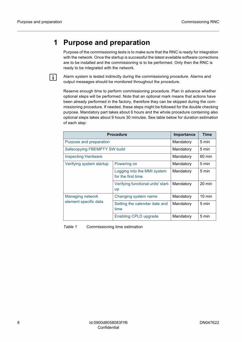
1 Purpose and preparationPurpose of the commissioning tests is to make sure that the RNC is ready for integration with the network. Once the startup is successful the latest available software corrections are to be installed and the commissioning is to be performed. Only then the RNC is ready to be integrated with the network.
g Alarm system is tested indirectly during the commissioning procedure. Alarms and output messages should be monitored throughout the procedure.
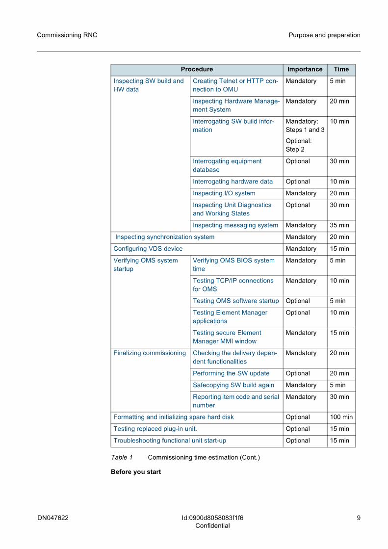
Reserve enough time to perform commissioning procedure. Plan in advance whether optional steps will be performed. Note that an optional mark means that actions have been already performed in the factory, therefore they can be skipped during the com-missioning procedure. If needed, these steps might be followed for the double checking purpose. Mandatory part takes about 6 hours and the whole procedure containing also optional steps takes about 9 hours 30 minutes. See table below for duration estimation of each step:
Procedure Importance Time
Purpose and preparation Mandatory 5 min
Safecopying FBEMPTY SW build Mandatory 5 min
Inspecting Hardware Mandatory 60 min
Verifying system startup Powering on Mandatory 5 min
Logging into the MMI system for the first time
Mandatory 5 min
Verifying functional units' start-up
Mandatory 20 min
Managing network element specific data
Changing system name Mandatory 10 min
Setting the calendar date and time
Mandatory 5 min
Enabling CPLD upgrade Mandatory 5 min
Table 1 Commissioning time estimation
DN047622 9
Commissioning RNC Purpose and preparation
Id:0900d8058083f1f6Confidential
Before you start
Inspecting SW build and HW data
Creating Telnet or HTTP con-nection to OMU
Mandatory 5 min
Inspecting Hardware Manage-ment System
Mandatory 20 min
Interrogating SW build infor-mation
Mandatory: Steps 1 and 3
Optional: Step 2
10 min
Interrogating equipment database
Optional 30 min
Interrogating hardware data Optional 10 min
Inspecting I/O system Mandatory 20 min
Inspecting Unit Diagnostics and Working States
Optional 30 min
Inspecting messaging system Mandatory 35 min
Inspecting synchronization system Mandatory 20 min
Configuring VDS device Mandatory 15 min
Verifying OMS system startup
Verifying OMS BIOS system time
Mandatory 5 min
Testing TCP/IP connections for OMS
Mandatory 10 min
Testing OMS software startup Optional 5 min
Testing Element Manager applications
Optional 10 min
Testing secure Element Manager MMI window
Mandatory 15 min
Finalizing commissioning Checking the delivery depen-dent functionalities
Mandatory 20 min
Performing the SW update Optional 20 min
Safecopying SW build again Mandatory 5 min
Reporting item code and serial number
Mandatory 30 min
Formatting and initializing spare hard disk Optional 100 min
Testing replaced plug-in unit. Optional 15 min
Troubleshooting functional unit start-up Optional 15 min
Procedure Importance Time
Table 1 Commissioning time estimation (Cont.)
10 DN047622
Commissioning RNC
Id:0900d8058083f1f6Confidential
Purpose and preparation
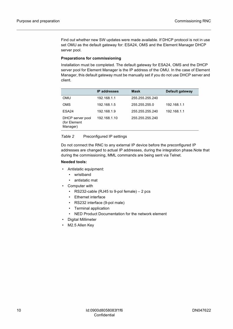
Find out whether new SW updates were made available. If DHCP protocol is not in use set OMU as the default gateway for: ESA24, OMS and the Element Manager DHCP server pool.
Preparations for commissioningInstallation must be completed. The default gateway for ESA24, OMS and the DHCP server pool for Element Manager is the IP address of the OMU. In the case of Element Manager, this default gateway must be manually set if you do not use DHCP server and client.
Do not connect the RNC to any external IP device before the preconfigured IP addresses are changed to actual IP addresses, during the integration phase.Note that during the commissioning, MML commands are being sent via Telnet.
Needed tools:
• Antistatic equipment: • wristband • antistatic mat
• Computer with • RS232-cable (RJ45 to 9-pol female) – 2 pcs • Ethernet interface • RS232 interface (9-pol male) • Terminal application • NED Product Documentation for the network element
• Digital Millimeter • M2.5 Allen Key
IP addresses Mask Default gateway
OMU 192.168.1.1 255.255.255.240
OMS 192.168.1.5 255.255.255.0 192.168.1.1
ESA24 192.168.1.9 255.255.255.240 192.168.1.1
DHCP server pool (for Element Manager)
192.168.1.10 255.255.255.240
Table 2 Preconfigured IP settings
DN047622 11
Commissioning RNC Safecopying FBEMPTY SW build
Id:0900d80580826017Confidential
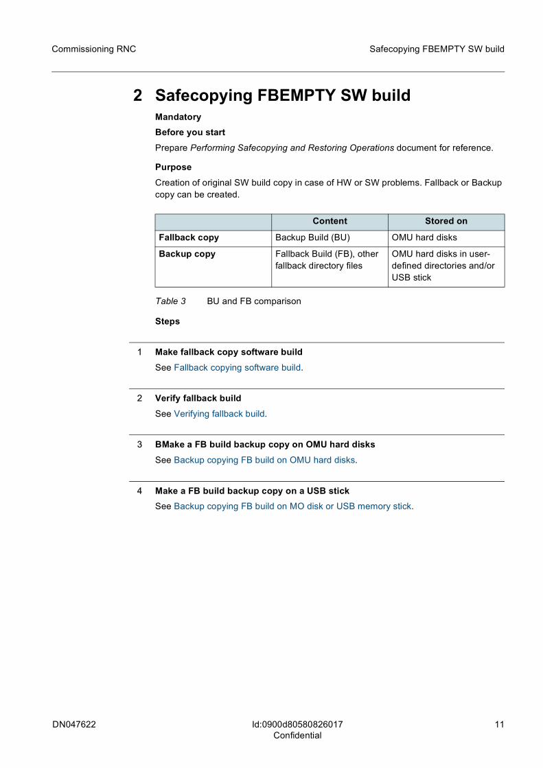
2 Safecopying FBEMPTY SW buildMandatoryBefore you startPrepare Performing Safecopying and Restoring Operations document for reference.
PurposeCreation of original SW build copy in case of HW or SW problems. Fallback or Backup copy can be created.
Steps
1 Make fallback copy software buildSee Fallback copying software build.
2 Verify fallback buildSee Verifying fallback build.
3 BMake a FB build backup copy on OMU hard disksSee Backup copying FB build on OMU hard disks.
4 Make a FB build backup copy on a USB stickSee Backup copying FB build on MO disk or USB memory stick.
Content Stored on
Fallback copy Backup Build (BU) OMU hard disks
Backup copy Fallback Build (FB), other fallback directory files
OMU hard disks in user-defined directories and/or USB stick
Table 3 BU and FB comparison
12 DN047622
Commissioning RNC
Id:0900d8058083f206Confidential
Inspecting Hardware
3 Inspecting Hardware Mandatory
PurposeEnsuring the RNC consists of properly located and correctly connected hardware.
Before you startPrint a copy of Commissioning Checklist document, and use it to keep track of the prog-ress, while performing commissioning procedure.Check access to the site documenta-tion describing standard hardware configurations. It is delivered together with the RNC, and is also available in PIC through NOLS. Moreover, links to referenced documents are gathered in Related information.It is recommended to carry out the commissioning checks before the power is on.
Steps
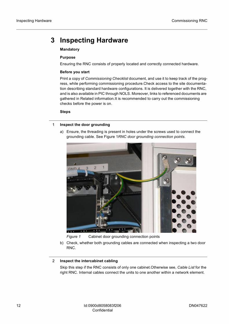
1 Inspect the door grounding
a) Ensure, the threading is present in holes under the screws used to connect the grounding cable. See Figure 1RNC door grounding connection points.
Figure 1 Cabinet door grounding connection pointsb) Check, whether both grounding cables are connected when inspecting a two door
RNC.
2 Inspect the intercabinet cablingSkip this step if the RNC consists of only one cabinet.Otherwise see, Cable List for the right RNC. Internal cables connect the units to one another within a network element.
DN047622 13
Commissioning RNC Inspecting Hardware
Id:0900d8058083f206Confidential
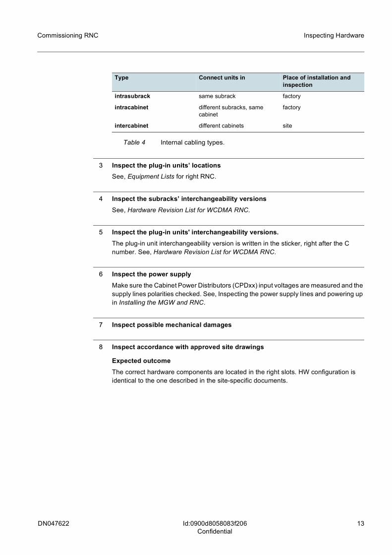
3 Inspect the plug-in units’ locationsSee, Equipment Lists for right RNC.
4 Inspect the subracks’ interchangeability versionsSee, Hardware Revision List for WCDMA RNC.
5 Inspect the plug-in units' interchangeability versions.The plug-in unit interchangeability version is written in the sticker, right after the C number. See, Hardware Revision List for WCDMA RNC.
6 Inspect the power supplyMake sure the Cabinet Power Distributors (CPDxx) input voltages are measured and the supply lines polarities checked. See, Inspecting the power supply lines and powering up in Installing the MGW and RNC.
7 Inspect possible mechanical damages
8 Inspect accordance with approved site drawings
Expected outcomeThe correct hardware components are located in the right slots. HW configuration is identical to the one described in the site-specific documents.
Type Connect units in Place of installation and inspection
intrasubrack same subrack factory
intracabinet different subracks, same cabinet
factory
intercabinet different cabinets site
Table 4 Internal cabling types.
14 DN047622
Commissioning RNC
Id:0900d8058083f216Confidential
Verifying system startup
4 Verifying system startup
4.1 Powering onMandatory
PurposePowering on the system for the first time.
Before you startIf DHCP protocol is not in use, configure the PC with predefined IP addresses manually. Remember to use appropriate subnet. If you have DHCP server and your DHCP client is running on the PC, no action is needed.
Steps
1 Power on the cabinet(s). Switch is at the top of the rack.
2 Check if LEDs on each starting up functional units are either blinking green, solid green or yellow.
Expected outcomeSystem is powered on.
DN047622 15
Commissioning RNC
Id:0900d8058083f212Confidential
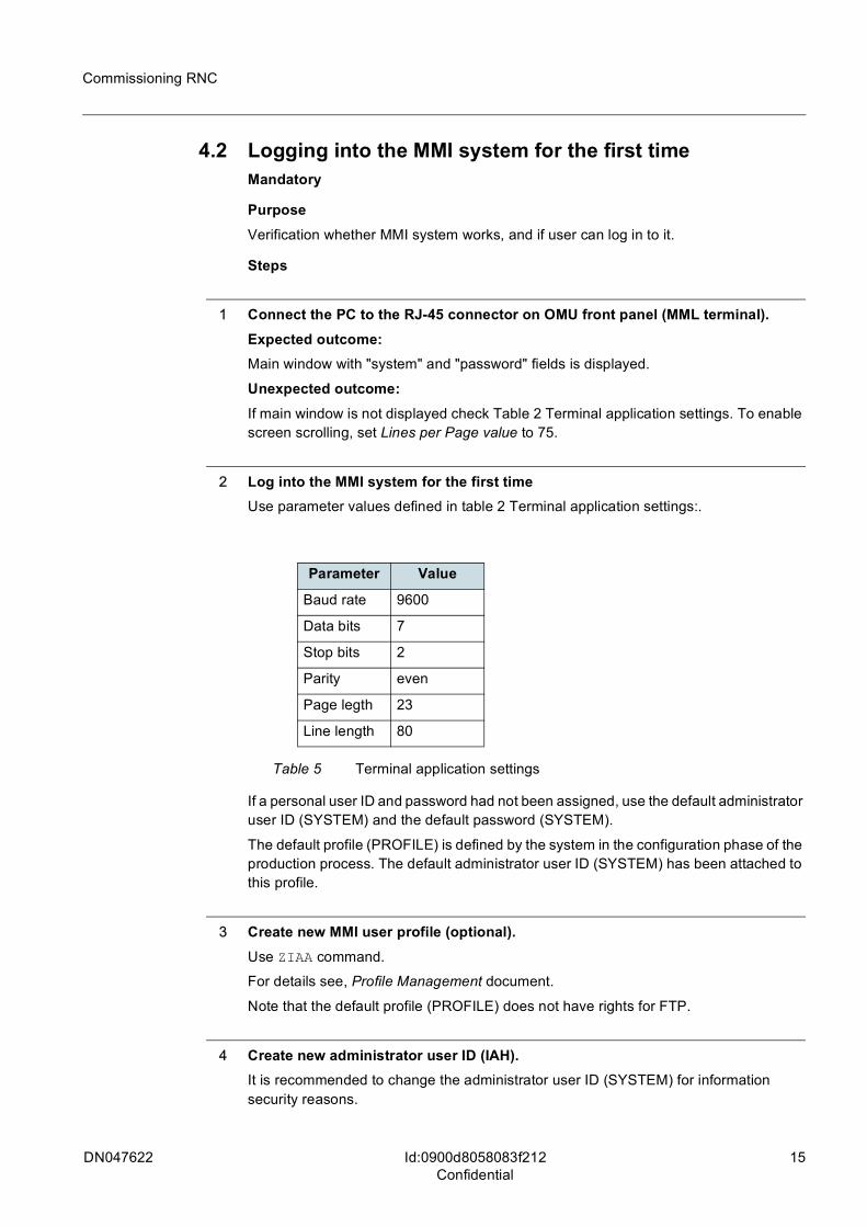
4.2 Logging into the MMI system for the first timeMandatory
PurposeVerification whether MMI system works, and if user can log in to it.
Steps
1 Connect the PC to the RJ-45 connector on OMU front panel (MML terminal).Expected outcome:Main window with "system" and "password" fields is displayed.
Unexpected outcome:If main window is not displayed check Table 2 Terminal application settings. To enable screen scrolling, set Lines per Page value to 75.
2 Log into the MMI system for the first timeUse parameter values defined in table 2 Terminal application settings:.
If a personal user ID and password had not been assigned, use the default administrator user ID (SYSTEM) and the default password (SYSTEM).
The default profile (PROFILE) is defined by the system in the configuration phase of the production process. The default administrator user ID (SYSTEM) has been attached to this profile.
3 Create new MMI user profile (optional).Use ZIAA command.
For details see, Profile Management document.
Note that the default profile (PROFILE) does not have rights for FTP.
4 Create new administrator user ID (IAH).It is recommended to change the administrator user ID (SYSTEM) for information security reasons.
Parameter Value
Baud rate 9600
Data bits 7
Stop bits 2
Parity even
Page legth 23
Line length 80
Table 5 Terminal application settings
16 DN047622
Commissioning RNC
Id:0900d8058083f212Confidential
ZIAH:<user id>:<profile>;
It is possible to specify the profile to which the user ID is attached.See, Profile Manage-ment document.
5 Log out.
6 Establish a new MML session with the new administrative user ID.
7 Delete default administrator user ID (SYSTEM) (IAD).ZIAD:<user id>;
Expected outcome:MMI system is accessible, new administrator user ID created and in use.
DN047622 17
Commissioning RNC
Id:0900d80580829ea7Confidential
4.3 Verifying functional units' start-upMandatory
PurposeEnsuring all the functional units are working as expected.
Before you startIf DHCP protocol is not in use, configure the PC with predefined IP addresses manually. Remember to use appropriate subnet. If you have DHCP server and your DHCP client is running on the PC, no action is needed.
Steps
1 Check that units are in WO-EX and SP-EX states (USI).ZUSI;
For further information, see Alarms and Recovery in Alarm Administration in RNC.
Expected outcome:No major alarms indicating HW errors.
Unexpected outcome:No major alarms indicating HW errors.
2 Check that no unnecessary alarms are on (AAP).ZAAP;
If a unit is not in the appropriate state, change the state with the ZUSC command.
Expected outcome:If some of the units are in inappropriate state, or HW errors are reported, refer to Appendix C: Troubleshooting functional unit start-up.
18 DN047622
Commissioning RNC
Id:0900d8058083f798Confidential
Managing network element specific data
5 Managing network element specific data
5.1 Changing system nameMandatory
PurposeIf multiple RNCs are working in the same network, it is recommended to assign unique system names for each one of them. It helps to manage and troubleshoot the HW and to keep track of the changes within the network.
DescriptionThe system name:
– is an ASCII string comprising of 11 characters– begins from offset 7 in the NECONF file– is IPA2800 by default – is shown in alarms
Displacement from record beginning, must be given as a hexadecimal number. The location information (consisting of 11 ASCII characters) in the NECONF file is changed in a similar way.
Steps
1 Take a backup copy of the NECONF file.Use the ZMM service terminal command.
ZMM:W0-LFILES/NECONFGX.IMG,W0-LFILES/NECONFGX.ORG
2 Display the first record from the NECONF file (DFD).ZDFD:<unit type>,[<unit index> | (<subscriber stage> | <pair number>),<unit index>]:<file number>,[[<byte number>... | <record number>...] | <all records or bytes> def],[<output filter> | A def],[<output mode> | B def],[<line length>];
3 Change the system name in the NECONF file (DFS).ZDFS:<unit type>,[<unit index> | (<subscriber stage> | <pair number>),<unit index>]:<file number>,[<displacement from file beginning>,<number of bytes to be substituted> | <record number>,<displacement from record beginning> | <record number>,<subrecord number>],[<input mode> | B def];
Use the space bar to move to the next character.
If the name is shorter than 11 characters, enter a binary zero "00" as the last character for the new name.
g Space bar is used for moving from one character to another. Hence, in ASCII mode, space character " " cannot be used. The underscore character "_" is a possible substi-tute. To use space character " " in the system name, re-edit the file in byte format.
DN047622 19
Commissioning RNC Managing network element specific data
Id:0900d8058083f798Confidential
4 Re-edit the file in byte format (DFS)If an underscore is not used, or system name is not shorter than 11 characters, then skip this step.
Give value B to the input mode parameter.
ZDFS:<unit type>,[<unit index> | (<subscriber stage> | <pair number>),<unit index>]:<file number>,[<displacement from file beginning>,<number of bytes to be substituted> | <record number>,<displacement from record beginning> | <record number>,<subrecord number>],[<input mode> | B def];
Use the space bar to move to the next character.
To change the underscore to a space, replace the hexadecimal 5F (underscore) with 20 (space).
To complete a system name that is shorter than 11 characters, replace the next non-relevant characters with binary zero(s) "00".
5 Verify the new name (DFD).Display the first record from the NECONF file again.
ZDFD:<unit type>,[<unit index> | (<subscriber stage> | <pair number>),<unit index>]:<file number>,[[<byte number>... | <record number>...] | <all records or bytes> def],[<output filter> | A def],[<output mode> | B def],[<line length>];
The output should show the new system name.
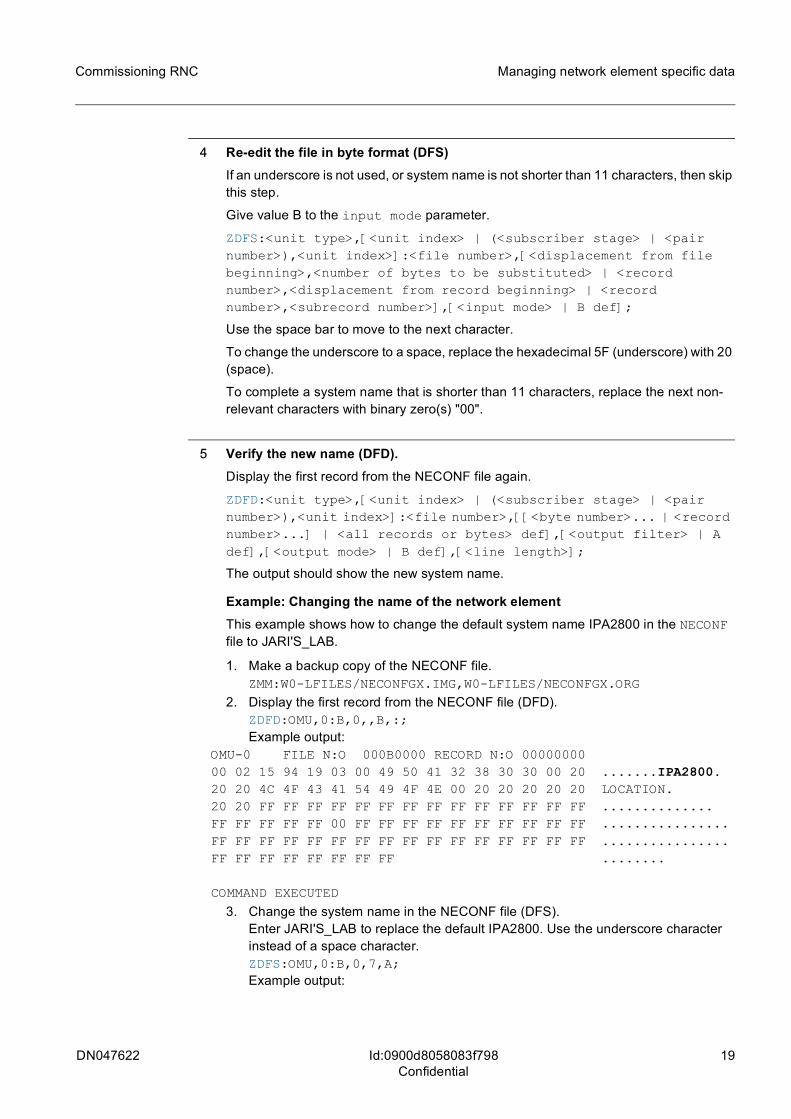
Example: Changing the name of the network elementThis example shows how to change the default system name IPA2800 in the NECONF file to JARI'S_LAB.
1. Make a backup copy of the NECONF file.ZMM:W0-LFILES/NECONFGX.IMG,W0-LFILES/NECONFGX.ORG
2. Display the first record from the NECONF file (DFD).ZDFD:OMU,0:B,0,,B,:;Example output:
OMU-0 FILE N:O 000B0000 RECORD N:O 0000000000 02 15 94 19 03 00 49 50 41 32 38 30 30 00 20 .......IPA2800.20 20 4C 4F 43 41 54 49 4F 4E 00 20 20 20 20 20 LOCATION.20 20 FF FF FF FF FF FF FF FF FF FF FF FF FF FF ..............FF FF FF FF FF 00 FF FF FF FF FF FF FF FF FF FF ................FF FF FF FF FF FF FF FF FF FF FF FF FF FF FF FF ................FF FF FF FF FF FF FF FF ........
COMMAND EXECUTED
3. Change the system name in the NECONF file (DFS).Enter JARI'S_LAB to replace the default IPA2800. Use the underscore character instead of a space character.ZDFS:OMU,0:B,0,7,A;Example output:
20 DN047622
Commissioning RNC
Id:0900d8058083f798Confidential
Managing network element specific data
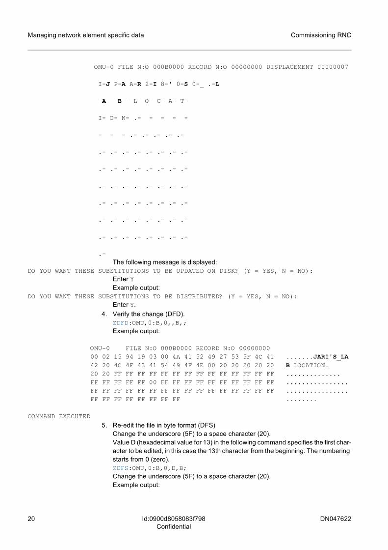
OMU-0 FILE N:O 000B0000 RECORD N:O 00000000 DISPLACEMENT 00000007
I-J P-A A-R 2-I 8-' 0-S 0-_ .-L
-A -B - L- O- C- A- T-
I- O- N- .- - - - -
- - - .- .- .- .- .-
.- .- .- .- .- .- .- .-
.- .- .- .- .- .- .- .-
.- .- .- .- .- .- .- .-
.- .- .- .- .- .- .- .-
.- .- .- .- .- .- .- .-
.- .- .- .- .- .- .- .-
.-The following message is displayed:
DO YOU WANT THESE SUBSTITUTIONS TO BE UPDATED ON DISK? (Y = YES, N = NO):Enter YExample output:
DO YOU WANT THESE SUBSTITUTIONS TO BE DISTRIBUTED? (Y = YES, N = NO):Enter Y.
4. Verify the change (DFD).ZDFD:OMU,0:B,0,,B,;Example output:
OMU-0 FILE N:O 000B0000 RECORD N:O 0000000000 02 15 94 19 03 00 4A 41 52 49 27 53 5F 4C 41 .......JARI'S_LA42 20 4C 4F 43 41 54 49 4F 4E 00 20 20 20 20 20 B LOCATION.20 20 FF FF FF FF FF FF FF FF FF FF FF FF FF FF ..............FF FF FF FF FF 00 FF FF FF FF FF FF FF FF FF FF ................FF FF FF FF FF FF FF FF FF FF FF FF FF FF FF FF ................FF FF FF FF FF FF FF FF ........
COMMAND EXECUTED5. Re-edit the file in byte format (DFS)
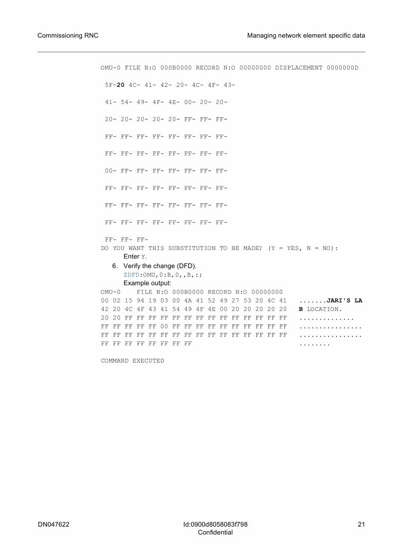
Change the underscore (5F) to a space character (20).Value D (hexadecimal value for 13) in the following command specifies the first char-acter to be edited, in this case the 13th character from the beginning. The numbering starts from 0 (zero).ZDFS:OMU,0:B,0,D,B;Change the underscore (5F) to a space character (20).Example output:
DN047622 21
Commissioning RNC Managing network element specific data
Id:0900d8058083f798Confidential
OMU-0 FILE N:O 000B0000 RECORD N:O 00000000 DISPLACEMENT 0000000D
5F-20 4C- 41- 42- 20- 4C- 4F- 43-
41- 54- 49- 4F- 4E- 00- 20- 20-
20- 20- 20- 20- 20- FF- FF- FF-
FF- FF- FF- FF- FF- FF- FF- FF-
FF- FF- FF- FF- FF- FF- FF- FF-
00- FF- FF- FF- FF- FF- FF- FF-
FF- FF- FF- FF- FF- FF- FF- FF-
FF- FF- FF- FF- FF- FF- FF- FF-
FF- FF- FF- FF- FF- FF- FF- FF-
FF- FF- FF-DO YOU WANT THIS SUBSTITUTION TO BE MADE? (Y = YES, N = NO):
Enter Y.6. Verify the change (DFD).
ZDFD:OMU,0:B,0,,B,:;Example output:
OMU-0 FILE N:O 000B0000 RECORD N:O 0000000000 02 15 94 19 03 00 4A 41 52 49 27 53 20 4C 41 .......JARI'S LA42 20 4C 4F 43 41 54 49 4F 4E 00 20 20 20 20 20 B LOCATION.20 20 FF FF FF FF FF FF FF FF FF FF FF FF FF FF ..............FF FF FF FF FF 00 FF FF FF FF FF FF FF FF FF FF ................FF FF FF FF FF FF FF FF FF FF FF FF FF FF FF FF ................FF FF FF FF FF FF FF FF ........
COMMAND EXECUTED
22 DN047622
Commissioning RNC
Id:0900d805808275f7Confidential
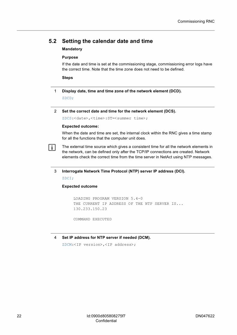
5.2 Setting the calendar date and timeMandatory
PurposeIf the date and time is set at the commissioning stage, commissioning error logs have the correct time. Note that the time zone does not need to be defined.
Steps
1 Display date, time and time zone of the network element (DCD).ZDCD;
2 Set the correct date and time for the network element (DCS).ZDCS:<date>,<time>:ST=<summer time>;
Expected outcome:When the date and time are set, the internal clock within the RNC gives a time stamp for all the functions that the computer unit does.
g The external time source which gives a consistent time for all the network elements in the network, can be defined only after the TCP/IP connections are created. Network elements check the correct time from the time server in NetAct using NTP messages.
3 Interrogate Network Time Protocol (NTP) server IP address (DCI).ZDCI;
Expected outcome
LOADING PROGRAM VERSION 5.4-0THE CURRENT IP ADDRESS OF THE NTP SERVER IS...130.233.150.23
COMMAND EXECUTED
4 Set IP address for NTP server if needed (DCM).ZDCM:<IP version>,<IP address>;
DN047622 23
Commissioning RNC
Id:0900d805808275feConfidential
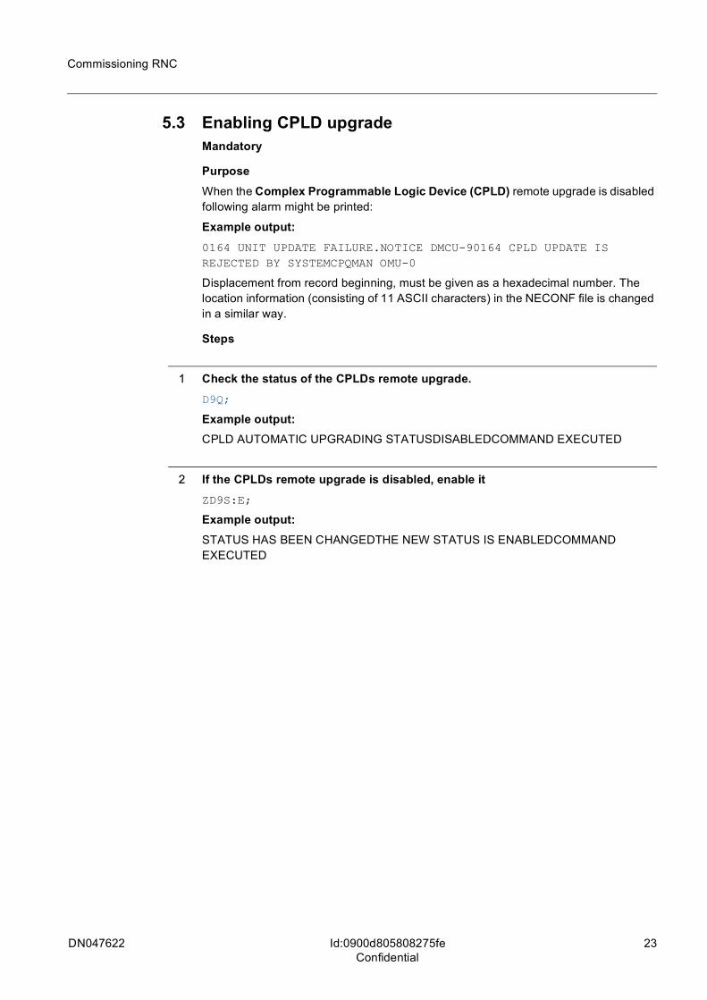
5.3 Enabling CPLD upgradeMandatory
PurposeWhen the Complex Programmable Logic Device (CPLD) remote upgrade is disabled following alarm might be printed:
Example output:0164 UNIT UPDATE FAILURE.NOTICE DMCU-90164 CPLD UPDATE IS REJECTED BY SYSTEMCPQMAN OMU-0
Displacement from record beginning, must be given as a hexadecimal number. The location information (consisting of 11 ASCII characters) in the NECONF file is changed in a similar way.
Steps
1 Check the status of the CPLDs remote upgrade.D9Q;
Example output:CPLD AUTOMATIC UPGRADING STATUSDISABLEDCOMMAND EXECUTED
2 If the CPLDs remote upgrade is disabled, enable itZD9S:E;
Example output:STATUS HAS BEEN CHANGEDTHE NEW STATUS IS ENABLEDCOMMAND EXECUTED
24 DN047622
Commissioning RNC
Id:0900d8058083f7abConfidential
Inspecting SW build and HW data
6 Inspecting SW build and HW data
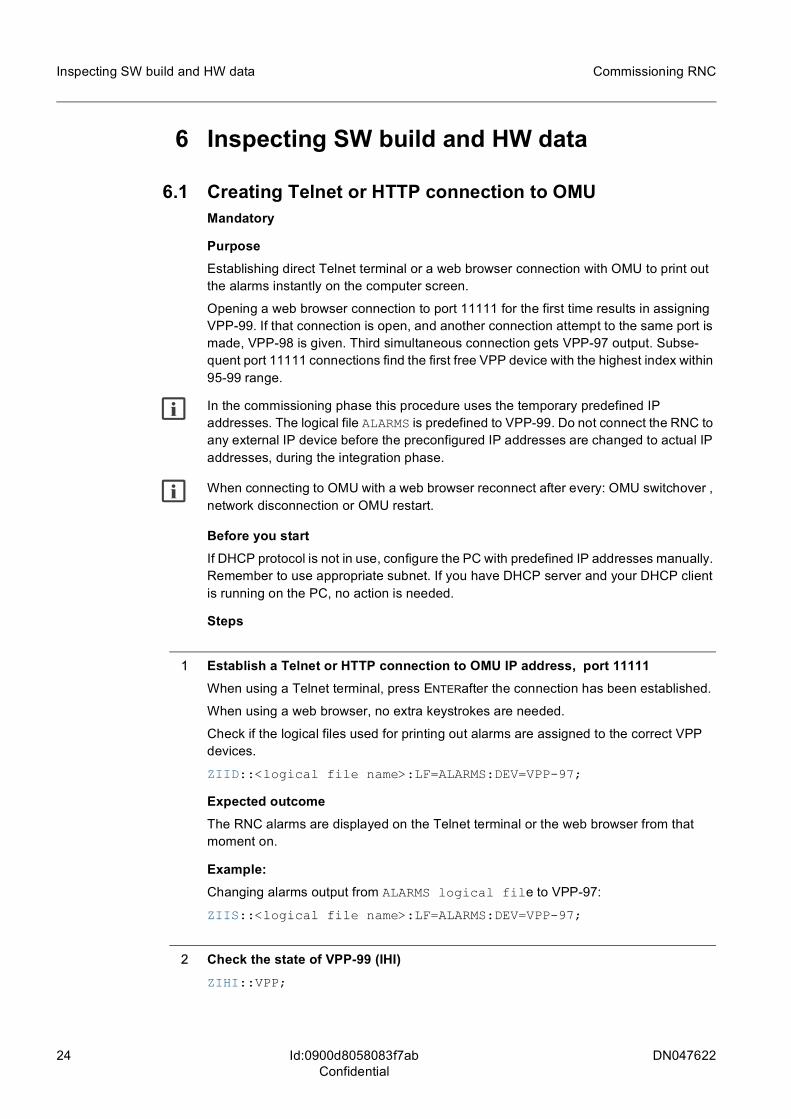
6.1 Creating Telnet or HTTP connection to OMUMandatory
PurposeEstablishing direct Telnet terminal or a web browser connection with OMU to print out the alarms instantly on the computer screen.
Opening a web browser connection to port 11111 for the first time results in assigning VPP-99. If that connection is open, and another connection attempt to the same port is made, VPP-98 is given. Third simultaneous connection gets VPP-97 output. Subse-quent port 11111 connections find the first free VPP device with the highest index within 95-99 range.
g In the commissioning phase this procedure uses the temporary predefined IP addresses. The logical file ALARMS is predefined to VPP-99. Do not connect the RNC to any external IP device before the preconfigured IP addresses are changed to actual IP addresses, during the integration phase.
g When connecting to OMU with a web browser reconnect after every: OMU switchover , network disconnection or OMU restart.
Before you startIf DHCP protocol is not in use, configure the PC with predefined IP addresses manually. Remember to use appropriate subnet. If you have DHCP server and your DHCP client is running on the PC, no action is needed.
Steps
1 Establish a Telnet or HTTP connection to OMU IP address, port 11111When using a Telnet terminal, press ENTERafter the connection has been established.
When using a web browser, no extra keystrokes are needed.
Check if the logical files used for printing out alarms are assigned to the correct VPP devices.
ZIID::<logical file name>:LF=ALARMS:DEV=VPP-97;
Expected outcomeThe RNC alarms are displayed on the Telnet terminal or the web browser from that moment on.
Example: Changing alarms output from ALARMS logical file to VPP-97:
ZIIS::<logical file name>:LF=ALARMS:DEV=VPP-97;
2 Check the state of VPP-99 (IHI)ZIHI::VPP;
DN047622 25
Commissioning RNC Inspecting SW build and HW data
Id:0900d8058083f7abConfidential
The alarm printing connection is established if VPP-99 is in WOEX state. Otherwise, reconnect to OMU, port 11111 from a Telnet terminal or web browser.
3 End the sessionStop alarm printing by closing the Telnet terminal or the web browser.
26 DN047622
Commissioning RNC
Id:0900d805808277c8Confidential
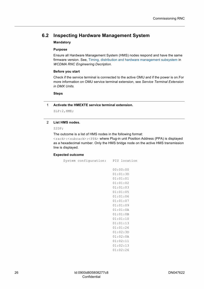
6.2 Inspecting Hardware Management System Mandatory
PurposeEnsure all Hardware Management System (HMS) nodes respond and have the same firmware version. See, Timing, distribution and hardware management subsystem in WCDMA RNC Engineering Decription.
Before you startCheck if the service terminal is connected to the active OMU and if the power is on.For more information on OMU service terminal extension, see Service Terminal Extension in DMX Units.
Steps
1 Activate the HMEXTE service terminal extension.ZLP:2,HME;
2 List HMS nodes.Z2DP;
The outcome is a list of HMS nodes in the following format: <rack>:<subrack>:<PPA> where Plug-in unit Position Address (PPA) is displayed as a hexadecimal number. Only the HMS bridge node on the active HMS transmission line is displayed.
Expected outcomeSystem configuration: PIU location
00:00:00 01:01:3D 01:01:01 01:01:02 01:01:03 01:01:05 01:01:06 01:01:07 01:01:09 01:01:0A 01:01:0B 01:01:10 01:01:13 01:01:26 01:02:3D 01:02:0A 01:02:11 01:02:13 01:02:26
DN047622 27
Commissioning RNC
Id:0900d805808277c8Confidential
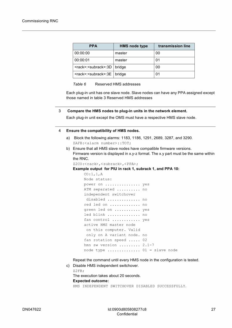
Each plug-in unit has one slave node. Slave nodes can have any PPA assigned except those named in table 3 Reserved HMS addresses
3 Compare the HMS nodes to plug-in units in the network element.Each plug-in unit except the OMS must have a respective HMS slave node.
4 Ensure the compatibility of HMS nodes.
a) Block the following alarms: 1183, 1186, 1291, 2689, 3287, and 3290.ZAFB:<alarm number>::TOT;
b) Ensure that all HMS slave nodes have compatible firmware versions.Firmware version is displayed in x.y-z format. The x.y part must be the same within the RNC.Z2CO:<rack>,<subrack>,<PPA>;Example output for PIU in rack 1, subrack 1, and PPA 10:
CO:1,1,ANode status:power on ............... yesATM separated .......... noindependent switchover disabled .............. nored led on ............. nogreen led on ........... yesled blink .............. nofan control ............ yesactive HMS master node on this computer. Valid only on A variant node. nofan rotation speed ..... 02hmn sw version ......... 2.1-7node type .............. 01 = slave node
Repeat the command until every HMS node in the configuration is tested.c) Disable HMS independent switchover.
Z2FB;The execution takes about 20 seconds.Expected outcome:HMS INDEPENDENT SWITCHOVER DISABLED SUCCESSFULLY.
PPA HMS node type transmission line
00:00:00 master 00
00:00:01 master 01
<rack>:<subrack>:3D bridge 00
<rack>:<subrack>:3E bridge 01
Table 6 Reserved HMS addresses
28 DN047622
Commissioning RNC
Id:0900d805808277c8Confidential
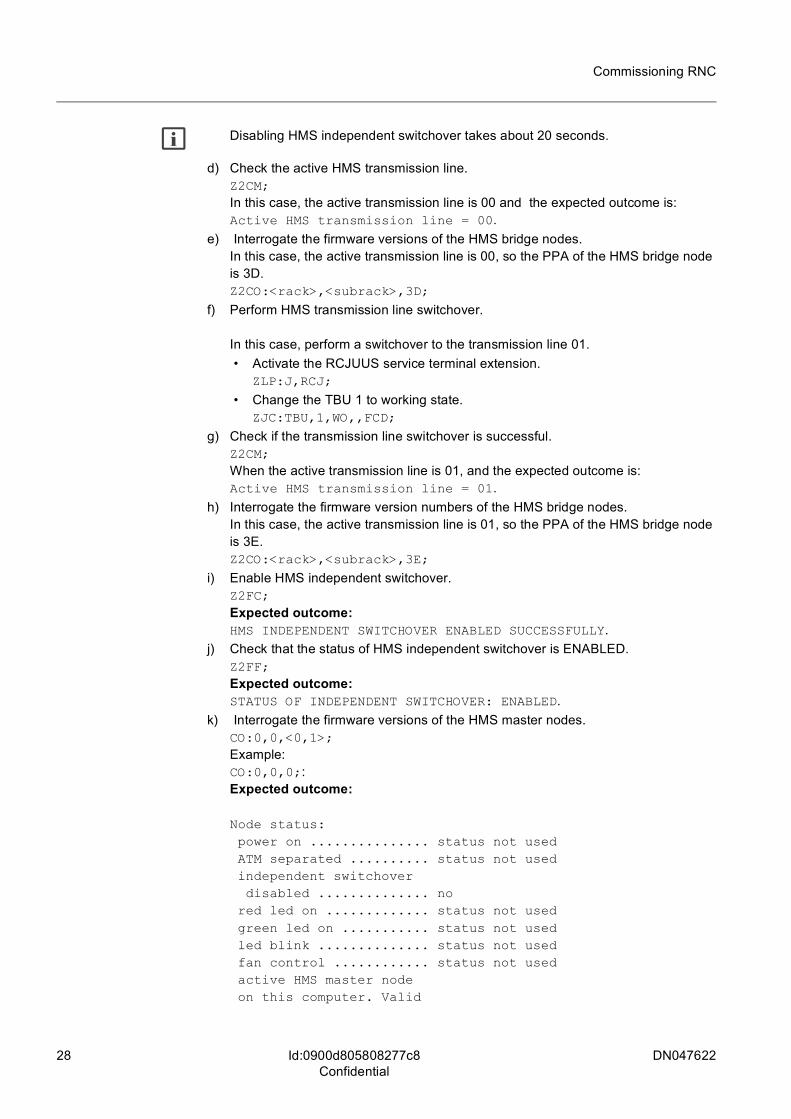
g Disabling HMS independent switchover takes about 20 seconds.
d) Check the active HMS transmission line.Z2CM;In this case, the active transmission line is 00 and the expected outcome is: Active HMS transmission line = 00.
e) Interrogate the firmware versions of the HMS bridge nodes.In this case, the active transmission line is 00, so the PPA of the HMS bridge node is 3D.Z2CO:<rack>,<subrack>,3D;
f) Perform HMS transmission line switchover.
In this case, perform a switchover to the transmission line 01. • Activate the RCJUUS service terminal extension.
ZLP:J,RCJ;
• Change the TBU 1 to working state.ZJC:TBU,1,WO,,FCD;
g) Check if the transmission line switchover is successful.Z2CM;When the active transmission line is 01, and the expected outcome is:Active HMS transmission line = 01.
h) Interrogate the firmware version numbers of the HMS bridge nodes.In this case, the active transmission line is 01, so the PPA of the HMS bridge node is 3E.Z2CO:<rack>,<subrack>,3E;
i) Enable HMS independent switchover.Z2FC;Expected outcome:HMS INDEPENDENT SWITCHOVER ENABLED SUCCESSFULLY.
j) Check that the status of HMS independent switchover is ENABLED.Z2FF;Expected outcome:STATUS OF INDEPENDENT SWITCHOVER: ENABLED.
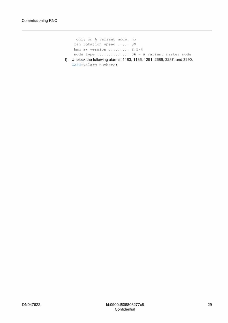
k) Interrogate the firmware versions of the HMS master nodes.CO:0,0,<0,1>;Example:CO:0,0,0;:Expected outcome:
Node status: power on ............... status not used ATM separated .......... status not used independent switchover disabled .............. no red led on ............. status not used green led on ........... status not used led blink .............. status not used fan control ............ status not used active HMS master node on this computer. Valid
DN047622 29
Commissioning RNC
Id:0900d805808277c8Confidential
only on A variant node. no fan rotation speed ..... 00 hmn sw version ......... 2.1-4 node type .............. 06 = A variant master node
l) Unblock the following alarms: 1183, 1186, 1291, 2689, 3287, and 3290.ZAFU:<alarm number>;
30 DN047622
Commissioning RNC
Id:0900d8058082781bConfidential
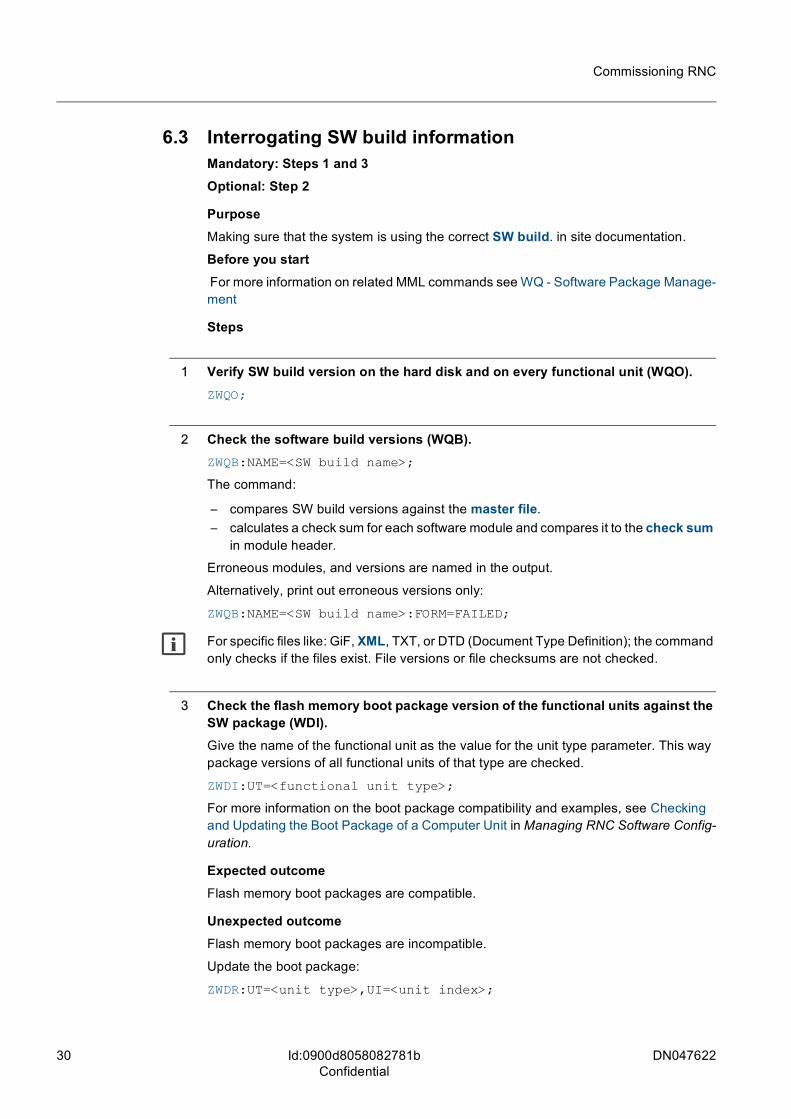
6.3 Interrogating SW build informationMandatory: Steps 1 and 3Optional: Step 2
PurposeMaking sure that the system is using the correct SW build. in site documentation.
Before you start For more information on related MML commands see WQ - Software Package Manage-ment
Steps
1 Verify SW build version on the hard disk and on every functional unit (WQO).ZWQO;
2 Check the software build versions (WQB).ZWQB:NAME=<SW build name>;
The command:
– compares SW build versions against the master file. – calculates a check sum for each software module and compares it to the check sum
in module header.
Erroneous modules, and versions are named in the output.
Alternatively, print out erroneous versions only:
ZWQB:NAME=<SW build name>:FORM=FAILED;
g For specific files like: GiF, XML, TXT, or DTD (Document Type Definition); the command only checks if the files exist. File versions or file checksums are not checked.
3 Check the flash memory boot package version of the functional units against the SW package (WDI).Give the name of the functional unit as the value for the unit type parameter. This way package versions of all functional units of that type are checked.
ZWDI:UT=<functional unit type>;
For more information on the boot package compatibility and examples, see Checking and Updating the Boot Package of a Computer Unit in Managing RNC Software Config-uration.
Expected outcomeFlash memory boot packages are compatible.
Unexpected outcomeFlash memory boot packages are incompatible.
Update the boot package:
ZWDR:UT=<unit type>,UI=<unit index>;

DN047622 31
Commissioning RNC
Id:0900d8058082781bConfidential
and take new boot package into use with command:
ZUSU:<unit type>,<unit index>;
32 DN047622
Commissioning RNC
Id:0900d8058083f7c9Confidential
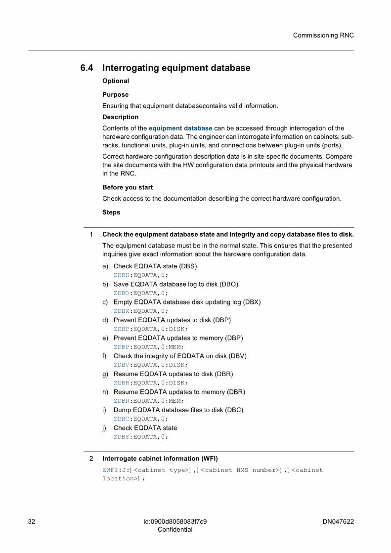
6.4 Interrogating equipment database Optional
PurposeEnsuring that equipment databasecontains valid information.
DescriptionContents of the equipment database can be accessed through interrogation of the hardware configuration data. The engineer can interrogate information on cabinets, sub-racks, functional units, plug-in units, and connections between plug-in units (ports).
Correct hardware configuration description data is in site-specific documents. Compare the site documents with the HW configuration data printouts and the physical hardware in the RNC.
Before you startCheck access to the documentation describing the correct hardware configuration.
Steps
1 Check the equipment database state and integrity and copy database files to disk.The equipment database must be in the normal state. This ensures that the presented inquiries give exact information about the hardware configuration data.
a) Check EQDATA state (DBS)ZDBS:EQDATA,0;
b) Save EQDATA database log to disk (DBO)ZDBO:EQDATA,0;
c) Empty EQDATA database disk updating log (DBX)ZDBX:EQDATA,0;
d) Prevent EQDATA updates to disk (DBP)ZDBP:EQDATA,0:DISK;
e) Prevent EQDATA updates to memory (DBP)ZDBP:EQDATA,0:MEM;
f) Check the integrity of EQDATA on disk (DBV)ZDBV:EQDATA,0:DISK;
g) Resume EQDATA updates to disk (DBR)ZDBR:EQDATA,0:DISK;
h) Resume EQDATA updates to memory (DBR)ZDBR:EQDATA,0:MEM;
i) Dump EQDATA database files to disk (DBC)ZDBC:EQDATA,0;
j) Check EQDATA stateZDBS:EQDATA,0;
2 Interrogate cabinet information (WFI)ZWFI:J:[<cabinet type>],[<cabinet HMS number>],[<cabinet location>];
DN047622 33
Commissioning RNC
Id:0900d8058083f7c9Confidential
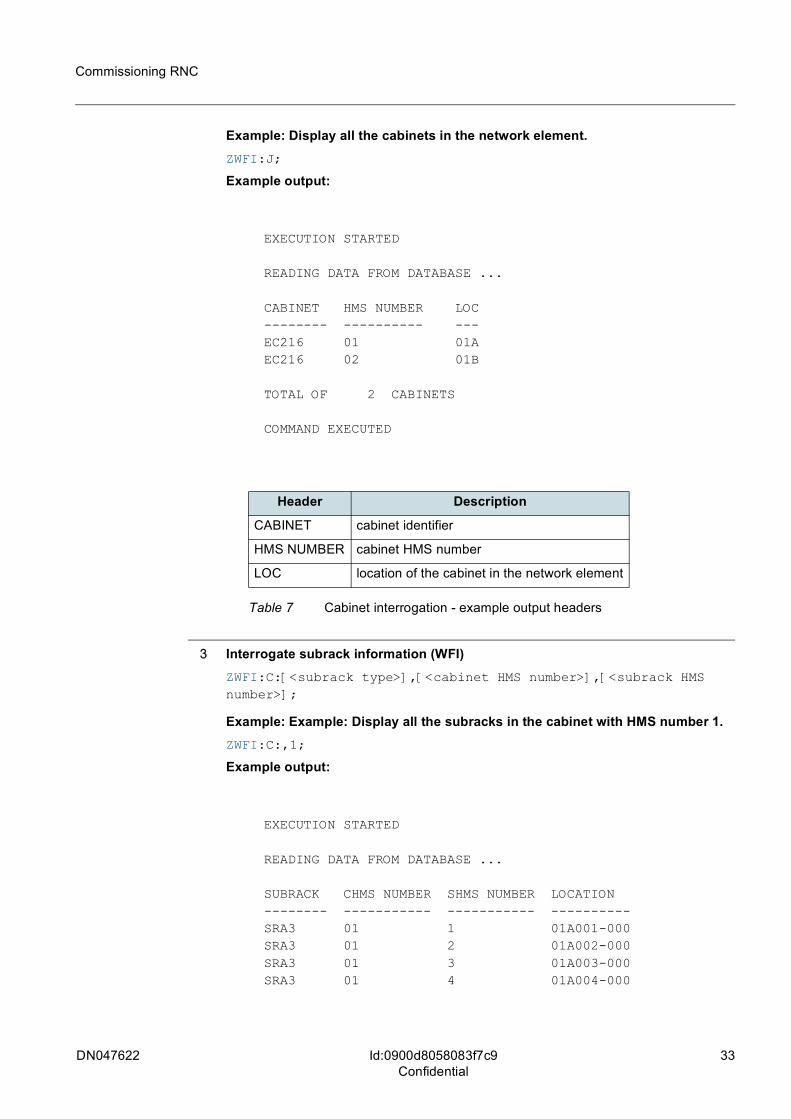
Example: Display all the cabinets in the network element.ZWFI:J;
Example output:
EXECUTION STARTED
READING DATA FROM DATABASE ...
CABINET HMS NUMBER LOC-------- ---------- ---EC216 01 01AEC216 02 01B
TOTAL OF 2 CABINETS
COMMAND EXECUTED
3 Interrogate subrack information (WFI)ZWFI:C:[<subrack type>],[<cabinet HMS number>],[<subrack HMS number>];
Example: Example: Display all the subracks in the cabinet with HMS number 1.ZWFI:C:,1;
Example output:
EXECUTION STARTED
READING DATA FROM DATABASE ...
SUBRACK CHMS NUMBER SHMS NUMBER LOCATION-------- ----------- ----------- ----------SRA3 01 1 01A001-000SRA3 01 2 01A002-000SRA3 01 3 01A003-000SRA3 01 4 01A004-000
Header Description
CABINET cabinet identifier
HMS NUMBER cabinet HMS number
LOC location of the cabinet in the network element
Table 7 Cabinet interrogation - example output headers
34 DN047622
Commissioning RNC
Id:0900d8058083f7c9Confidential
TOTAL OF 4 SUBRACKS
COMMAND EXECUTED
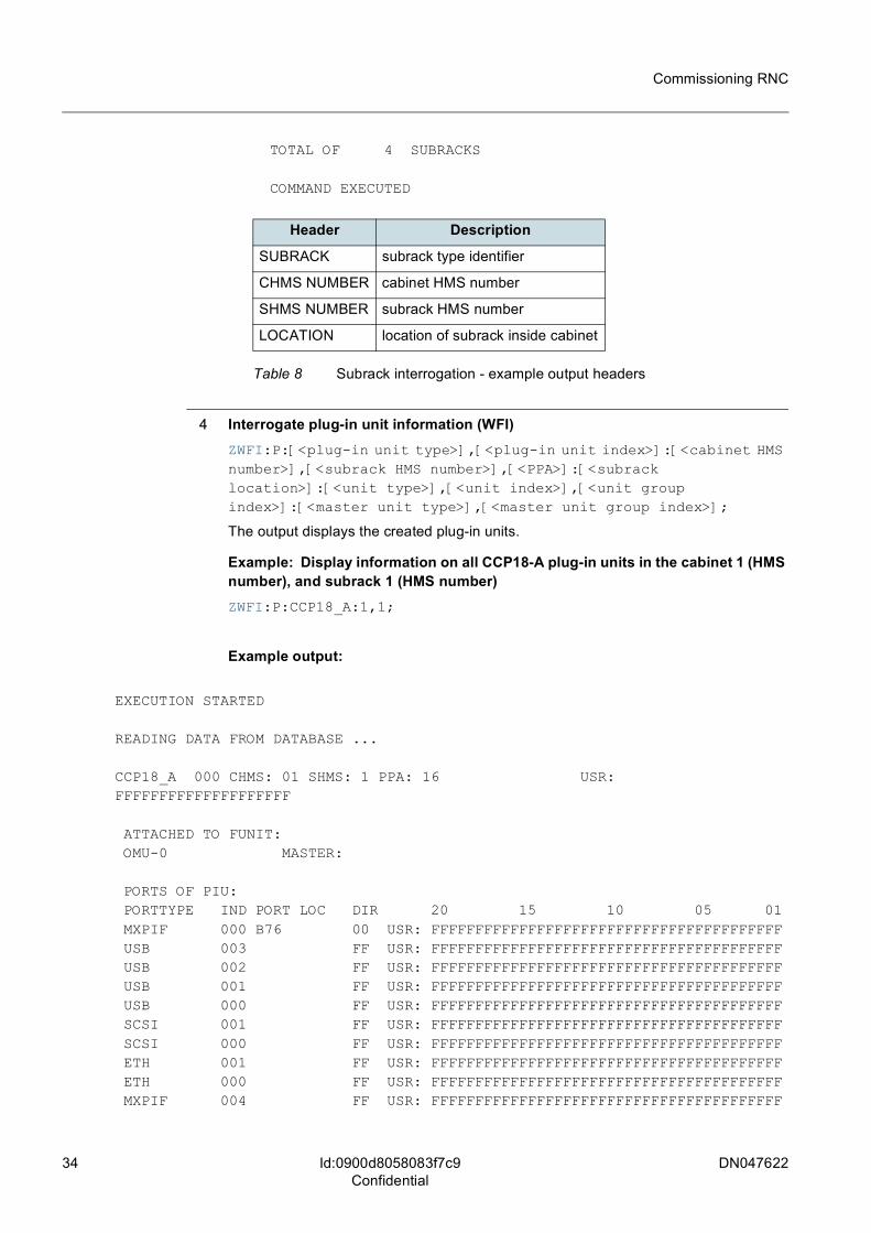
4 Interrogate plug-in unit information (WFI)ZWFI:P:[<plug-in unit type>],[<plug-in unit index>]:[<cabinet HMS number>],[<subrack HMS number>],[<PPA>]:[<subrack location>]:[<unit type>],[<unit index>],[<unit group index>]:[<master unit type>],[<master unit group index>];
The output displays the created plug-in units.
Example: Display information on all CCP18-A plug-in units in the cabinet 1 (HMS number), and subrack 1 (HMS number)ZWFI:P:CCP18_A:1,1;
Example output:
EXECUTION STARTED
READING DATA FROM DATABASE ...
CCP18_A 000 CHMS: 01 SHMS: 1 PPA: 16 USR: FFFFFFFFFFFFFFFFFFFF
ATTACHED TO FUNIT: OMU-0 MASTER:
PORTS OF PIU: PORTTYPE IND PORT LOC DIR 20 15 10 05 01 MXPIF 000 B76 00 USR: FFFFFFFFFFFFFFFFFFFFFFFFFFFFFFFFFFFFFFFF USB 003 FF USR: FFFFFFFFFFFFFFFFFFFFFFFFFFFFFFFFFFFFFFFF USB 002 FF USR: FFFFFFFFFFFFFFFFFFFFFFFFFFFFFFFFFFFFFFFF USB 001 FF USR: FFFFFFFFFFFFFFFFFFFFFFFFFFFFFFFFFFFFFFFF USB 000 FF USR: FFFFFFFFFFFFFFFFFFFFFFFFFFFFFFFFFFFFFFFF SCSI 001 FF USR: FFFFFFFFFFFFFFFFFFFFFFFFFFFFFFFFFFFFFFFF SCSI 000 FF USR: FFFFFFFFFFFFFFFFFFFFFFFFFFFFFFFFFFFFFFFF ETH 001 FF USR: FFFFFFFFFFFFFFFFFFFFFFFFFFFFFFFFFFFFFFFF ETH 000 FF USR: FFFFFFFFFFFFFFFFFFFFFFFFFFFFFFFFFFFFFFFF MXPIF 004 FF USR: FFFFFFFFFFFFFFFFFFFFFFFFFFFFFFFFFFFFFFFF
Header Description
SUBRACK subrack type identifier
CHMS NUMBER cabinet HMS number
SHMS NUMBER subrack HMS number
LOCATION location of subrack inside cabinet
Table 8 Subrack interrogation - example output headers
DN047622 35
Commissioning RNC
Id:0900d8058083f7c9Confidential
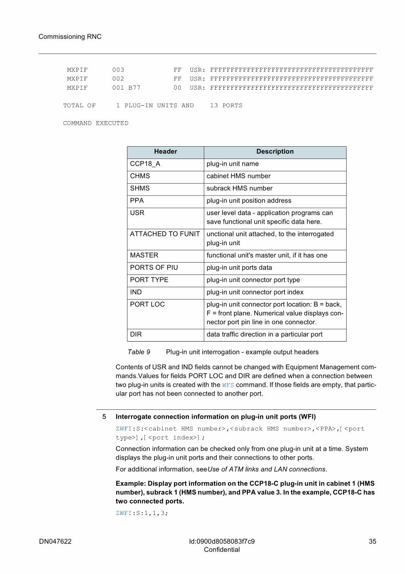
MXPIF 003 FF USR: FFFFFFFFFFFFFFFFFFFFFFFFFFFFFFFFFFFFFFFF MXPIF 002 FF USR: FFFFFFFFFFFFFFFFFFFFFFFFFFFFFFFFFFFFFFFF MXPIF 001 B77 00 USR: FFFFFFFFFFFFFFFFFFFFFFFFFFFFFFFFFFFFFFFF
TOTAL OF 1 PLUG-IN UNITS AND 13 PORTS
COMMAND EXECUTED
Contents of USR and IND fields cannot be changed with Equipment Management com-mands.Values for fields PORT LOC and DIR are defined when a connection between two plug-in units is created with the WFS command. If those fields are empty, that partic-ular port has not been connected to another port.
5 Interrogate connection information on plug-in unit ports (WFI)ZWFI:S:<cabinet HMS number>,<subrack HMS number>,<PPA>,[<port type>],[<port index>];
Connection information can be checked only from one plug-in unit at a time. System displays the plug-in unit ports and their connections to other ports.
For additional information, seeUse of ATM links and LAN connections.
Example: Display port information on the CCP18-C plug-in unit in cabinet 1 (HMS number), subrack 1 (HMS number), and PPA value 3. In the example, CCP18-C has two connected ports.ZWFI:S:1,1,3;
Header Description
CCP18_A plug-in unit name
CHMS cabinet HMS number
SHMS subrack HMS number
PPA plug-in unit position address
USR user level data - application programs can save functional unit specific data here.
ATTACHED TO FUNIT unctional unit attached, to the interrogated plug-in unit
MASTER functional unit's master unit, if it has one
PORTS OF PIU plug-in unit ports data
PORT TYPE plug-in unit connector port type
IND plug-in unit connector port index
PORT LOC plug-in unit connector port location: B = back, F = front plane. Numerical value displays con-nector port pin line in one connector.
DIR data traffic direction in a particular port
Table 9 Plug-in unit interrogation - example output headers
36 DN047622
Commissioning RNC
Id:0900d8058083f7c9Confidential
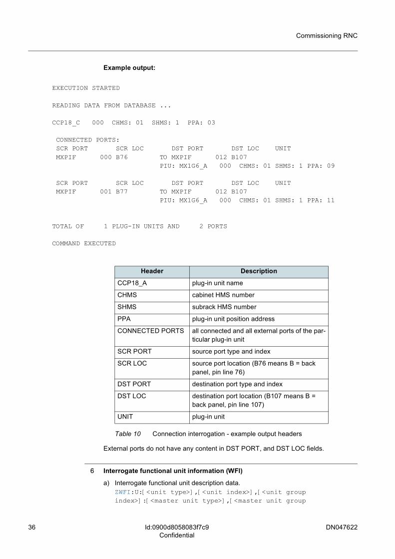
Example output:
EXECUTION STARTED
READING DATA FROM DATABASE ...
CCP18_C 000 CHMS: 01 SHMS: 1 PPA: 03
CONNECTED PORTS: SCR PORT SCR LOC DST PORT DST LOC UNIT MXPIF 000 B76 TO MXPIF 012 B107
PIU: MX1G6_A 000 CHMS: 01 SHMS: 1 PPA: 09
SCR PORT SCR LOC DST PORT DST LOC UNIT MXPIF 001 B77 TO MXPIF 012 B107
PIU: MX1G6_A 000 CHMS: 01 SHMS: 1 PPA: 11
TOTAL OF 1 PLUG-IN UNITS AND 2 PORTS
COMMAND EXECUTED
External ports do not have any content in DST PORT, and DST LOC fields.
6 Interrogate functional unit information (WFI)
a) Interrogate functional unit description data.ZWFI:U:[<unit type>],[<unit index>],[<unit group index>]:[<master unit type>],[<master unit group
Header Description
CCP18_A plug-in unit name
CHMS cabinet HMS number
SHMS subrack HMS number
PPA plug-in unit position address
CONNECTED PORTS all connected and all external ports of the par-ticular plug-in unit
SCR PORT source port type and index
SCR LOC source port location (B76 means B = back panel, pin line 76)
DST PORT destination port type and index
DST LOC destination port location (B107 means B = back panel, pin line 107)
UNIT plug-in unit
Table 10 Connection interrogation - example output headers
DN047622 37
Commissioning RNC
Id:0900d8058083f7c9Confidential
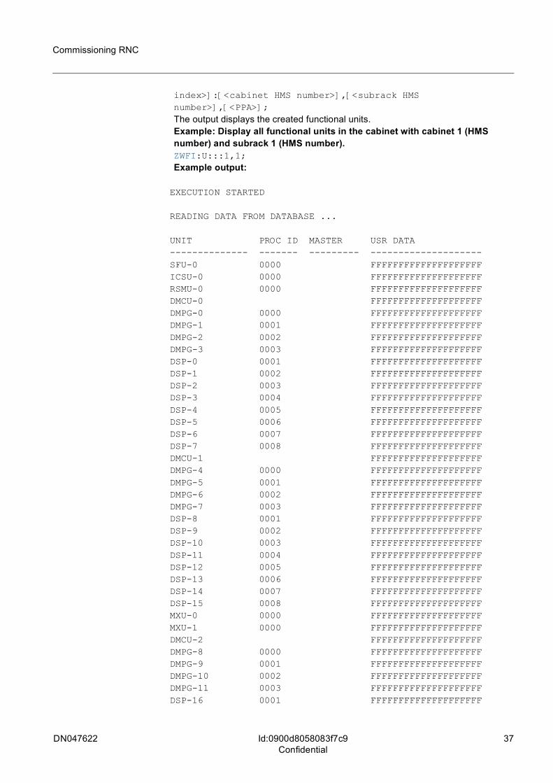
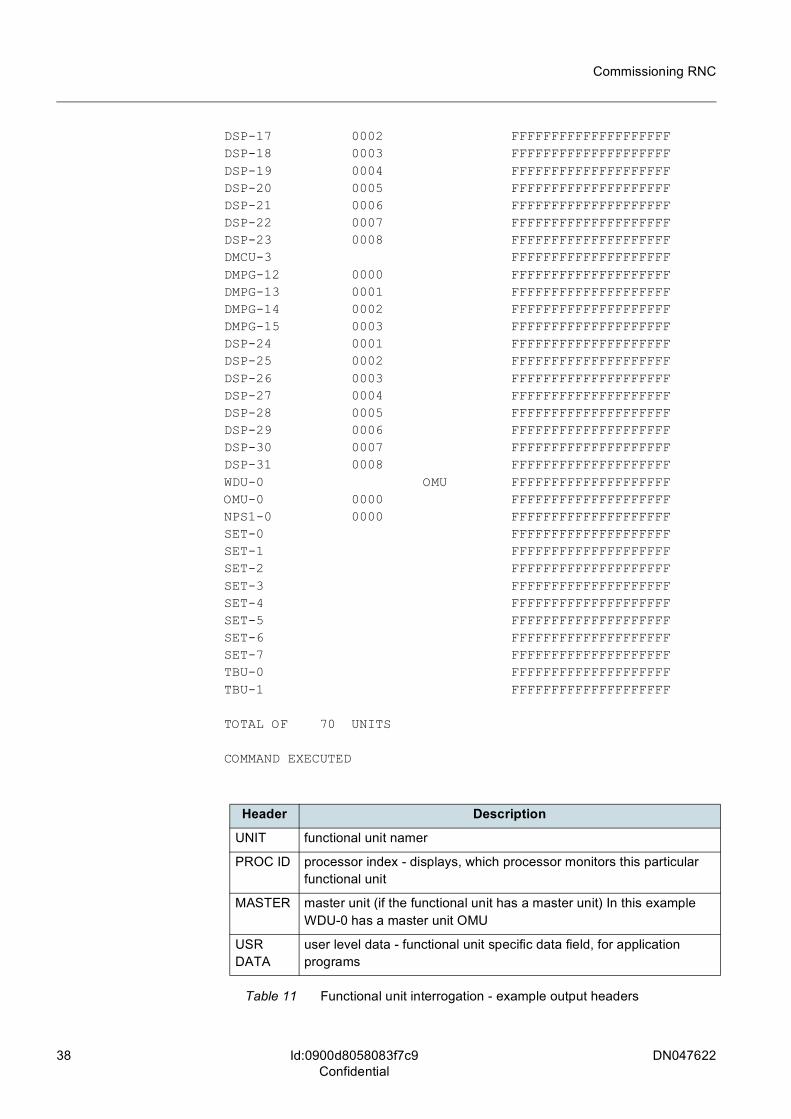
index>]:[<cabinet HMS number>],[<subrack HMS number>],[<PPA>];The output displays the created functional units.Example: Display all functional units in the cabinet with cabinet 1 (HMS number) and subrack 1 (HMS number).ZWFI:U:::1,1;Example output:
EXECUTION STARTED
READING DATA FROM DATABASE ...
UNIT PROC ID MASTER USR DATA-------------- ------- --------- --------------------SFU-0 0000 FFFFFFFFFFFFFFFFFFFFICSU-0 0000 FFFFFFFFFFFFFFFFFFFFRSMU-0 0000 FFFFFFFFFFFFFFFFFFFFDMCU-0 FFFFFFFFFFFFFFFFFFFFDMPG-0 0000 FFFFFFFFFFFFFFFFFFFFDMPG-1 0001 FFFFFFFFFFFFFFFFFFFFDMPG-2 0002 FFFFFFFFFFFFFFFFFFFFDMPG-3 0003 FFFFFFFFFFFFFFFFFFFFDSP-0 0001 FFFFFFFFFFFFFFFFFFFFDSP-1 0002 FFFFFFFFFFFFFFFFFFFFDSP-2 0003 FFFFFFFFFFFFFFFFFFFFDSP-3 0004 FFFFFFFFFFFFFFFFFFFFDSP-4 0005 FFFFFFFFFFFFFFFFFFFFDSP-5 0006 FFFFFFFFFFFFFFFFFFFFDSP-6 0007 FFFFFFFFFFFFFFFFFFFFDSP-7 0008 FFFFFFFFFFFFFFFFFFFFDMCU-1 FFFFFFFFFFFFFFFFFFFFDMPG-4 0000 FFFFFFFFFFFFFFFFFFFFDMPG-5 0001 FFFFFFFFFFFFFFFFFFFFDMPG-6 0002 FFFFFFFFFFFFFFFFFFFFDMPG-7 0003 FFFFFFFFFFFFFFFFFFFFDSP-8 0001 FFFFFFFFFFFFFFFFFFFFDSP-9 0002 FFFFFFFFFFFFFFFFFFFFDSP-10 0003 FFFFFFFFFFFFFFFFFFFFDSP-11 0004 FFFFFFFFFFFFFFFFFFFFDSP-12 0005 FFFFFFFFFFFFFFFFFFFFDSP-13 0006 FFFFFFFFFFFFFFFFFFFFDSP-14 0007 FFFFFFFFFFFFFFFFFFFFDSP-15 0008 FFFFFFFFFFFFFFFFFFFFMXU-0 0000 FFFFFFFFFFFFFFFFFFFFMXU-1 0000 FFFFFFFFFFFFFFFFFFFFDMCU-2 FFFFFFFFFFFFFFFFFFFFDMPG-8 0000 FFFFFFFFFFFFFFFFFFFFDMPG-9 0001 FFFFFFFFFFFFFFFFFFFFDMPG-10 0002 FFFFFFFFFFFFFFFFFFFFDMPG-11 0003 FFFFFFFFFFFFFFFFFFFFDSP-16 0001 FFFFFFFFFFFFFFFFFFFF
38 DN047622
Commissioning RNC
Id:0900d8058083f7c9Confidential
DSP-17 0002 FFFFFFFFFFFFFFFFFFFFDSP-18 0003 FFFFFFFFFFFFFFFFFFFFDSP-19 0004 FFFFFFFFFFFFFFFFFFFFDSP-20 0005 FFFFFFFFFFFFFFFFFFFFDSP-21 0006 FFFFFFFFFFFFFFFFFFFFDSP-22 0007 FFFFFFFFFFFFFFFFFFFFDSP-23 0008 FFFFFFFFFFFFFFFFFFFFDMCU-3 FFFFFFFFFFFFFFFFFFFFDMPG-12 0000 FFFFFFFFFFFFFFFFFFFFDMPG-13 0001 FFFFFFFFFFFFFFFFFFFFDMPG-14 0002 FFFFFFFFFFFFFFFFFFFFDMPG-15 0003 FFFFFFFFFFFFFFFFFFFFDSP-24 0001 FFFFFFFFFFFFFFFFFFFFDSP-25 0002 FFFFFFFFFFFFFFFFFFFFDSP-26 0003 FFFFFFFFFFFFFFFFFFFFDSP-27 0004 FFFFFFFFFFFFFFFFFFFFDSP-28 0005 FFFFFFFFFFFFFFFFFFFFDSP-29 0006 FFFFFFFFFFFFFFFFFFFFDSP-30 0007 FFFFFFFFFFFFFFFFFFFFDSP-31 0008 FFFFFFFFFFFFFFFFFFFFWDU-0 OMU FFFFFFFFFFFFFFFFFFFFOMU-0 0000 FFFFFFFFFFFFFFFFFFFFNPS1-0 0000 FFFFFFFFFFFFFFFFFFFFSET-0 FFFFFFFFFFFFFFFFFFFFSET-1 FFFFFFFFFFFFFFFFFFFFSET-2 FFFFFFFFFFFFFFFFFFFFSET-3 FFFFFFFFFFFFFFFFFFFFSET-4 FFFFFFFFFFFFFFFFFFFFSET-5 FFFFFFFFFFFFFFFFFFFFSET-6 FFFFFFFFFFFFFFFFFFFFSET-7 FFFFFFFFFFFFFFFFFFFFTBU-0 FFFFFFFFFFFFFFFFFFFFTBU-1 FFFFFFFFFFFFFFFFFFFF
TOTAL OF 70 UNITS
COMMAND EXECUTED
Header Description
UNIT functional unit namer
PROC ID processor index - displays, which processor monitors this particular functional unit
MASTER master unit (if the functional unit has a master unit) In this example WDU-0 has a master unit OMU
USR DATA
user level data - functional unit specific data field, for application programs
Table 11 Functional unit interrogation - example output headers
DN047622 39
Commissioning RNC
Id:0900d8058083f7c9Confidential
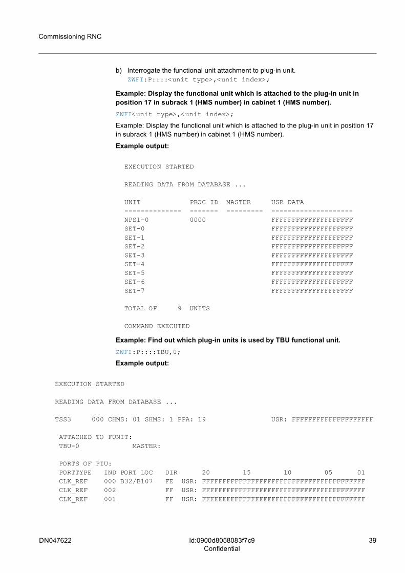
b) Interrogate the functional unit attachment to plug-in unit.ZWFI:P::::<unit type>,<unit index>;
Example: Display the functional unit which is attached to the plug-in unit in position 17 in subrack 1 (HMS number) in cabinet 1 (HMS number).ZWFI<unit type>,<unit index>;
Example: Display the functional unit which is attached to the plug-in unit in position 17 in subrack 1 (HMS number) in cabinet 1 (HMS number).
Example output:
EXECUTION STARTED
READING DATA FROM DATABASE ...
UNIT PROC ID MASTER USR DATA-------------- ------- --------- --------------------NPS1-0 0000 FFFFFFFFFFFFFFFFFFFFSET-0 FFFFFFFFFFFFFFFFFFFFSET-1 FFFFFFFFFFFFFFFFFFFFSET-2 FFFFFFFFFFFFFFFFFFFFSET-3 FFFFFFFFFFFFFFFFFFFFSET-4 FFFFFFFFFFFFFFFFFFFFSET-5 FFFFFFFFFFFFFFFFFFFFSET-6 FFFFFFFFFFFFFFFFFFFFSET-7 FFFFFFFFFFFFFFFFFFFF
TOTAL OF 9 UNITS
COMMAND EXECUTED
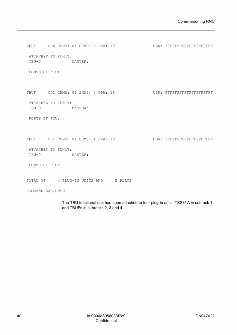
Example: Find out which plug-in units is used by TBU functional unit.ZWFI:P::::TBU,0;
Example output:
EXECUTION STARTED
READING DATA FROM DATABASE ...
TSS3 000 CHMS: 01 SHMS: 1 PPA: 19 USR: FFFFFFFFFFFFFFFFFFFF
ATTACHED TO FUNIT: TBU-0 MASTER:
PORTS OF PIU: PORTTYPE IND PORT LOC DIR 20 15 10 05 01 CLK_REF 000 B32/B107 FE USR: FFFFFFFFFFFFFFFFFFFFFFFFFFFFFFFFFFFFFFFF CLK_REF 002 FF USR: FFFFFFFFFFFFFFFFFFFFFFFFFFFFFFFFFFFFFFFF CLK_REF 001 FF USR: FFFFFFFFFFFFFFFFFFFFFFFFFFFFFFFFFFFFFFFF
40 DN047622
Commissioning RNC
Id:0900d8058083f7c9Confidential
TBUF 000 CHMS: 01 SHMS: 2 PPA: 19 USR: FFFFFFFFFFFFFFFFFFFF
ATTACHED TO FUNIT: TBU-0 MASTER:
PORTS OF PIU:
TBUF 001 CHMS: 01 SHMS: 3 PPA: 19 USR: FFFFFFFFFFFFFFFFFFFF
ATTACHED TO FUNIT: TBU-0 MASTER:
PORTS OF PIU:
TBUF 002 CHMS: 01 SHMS: 4 PPA: 19 USR: FFFFFFFFFFFFFFFFFFFF
ATTACHED TO FUNIT: TBU-0 MASTER:
PORTS OF PIU:
TOTAL OF 4 PLUG-IN UNITS AND 3 PORTS
COMMAND EXECUTED
The TBU functional unit has been attached to four plug-in units: TSS3/-A in subrack 1, and TBUFs in subracks 2, 3 and 4.
DN047622 41
Commissioning RNC
Id:0900d8058083f7d5Confidential
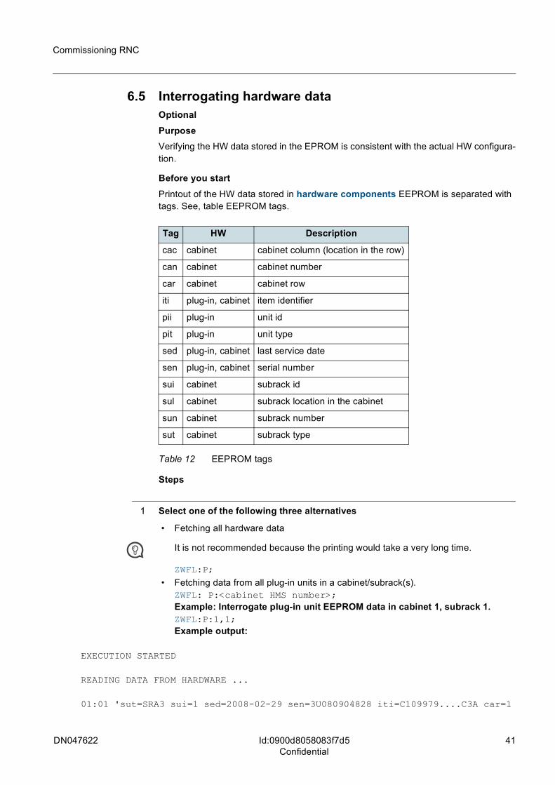
6.5 Interrogating hardware dataOptionalPurposeVerifying the HW data stored in the EPROM is consistent with the actual HW configura-tion.
Before you startPrintout of the HW data stored in hardware components EEPROM is separated with tags. See, table EEPROM tags.
Steps
1 Select one of the following three alternatives
• Fetching all hardware data
t It is not recommended because the printing would take a very long time.
ZWFL:P;
• Fetching data from all plug-in units in a cabinet/subrack(s).ZWFL: P:<cabinet HMS number>;Example: Interrogate plug-in unit EEPROM data in cabinet 1, subrack 1.ZWFL:P:1,1;Example output:
EXECUTION STARTED
READING DATA FROM HARDWARE ...
01:01 'sut=SRA3 sui=1 sed=2008-02-29 sen=3U080904828 iti=C109979....C3A car=1
Tag HW Description
cac cabinet cabinet column (location in the row)
can cabinet cabinet number
car cabinet cabinet row
iti plug-in, cabinet item identifier
pii plug-in unit id
pit plug-in unit type
sed plug-in, cabinet last service date
sen plug-in, cabinet serial number
sui cabinet subrack id
sul cabinet subrack location in the cabinet
sun cabinet subrack number
sut cabinet subrack type
Table 12 EEPROM tags
42 DN047622
Commissioning RNC
Id:0900d8058083f7d5Confidential
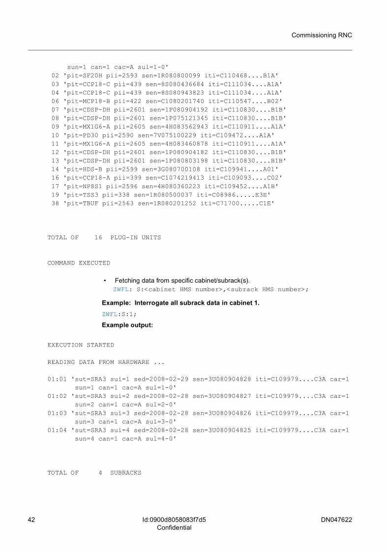
sun=1 can=1 cac=A sul=1-0' 02 'pit=SF20H pii=2593 sen=1R080800099 iti=C110468....B1A' 03 'pit=CCP18-C pii=439 sen=8S080436684 iti=C111034....A1A' 04 'pit=CCP18-C pii=439 sen=8S080943823 iti=C111034....A1A' 06 'pit=MCP18-B pii=422 sen=C1080201740 iti=C110547....B02' 07 'pit=CDSP-DH pii=2601 sen=1P080904192 iti=C110830....B1B' 08 'pit=CDSP-DH pii=2601 sen=1P075121345 iti=C110830....B1B' 09 'pit=MX1G6-A pii=2605 sen=4H083562943 iti=C110911....A1A' 10 'pit=PD30 pii=2590 sen=7V075100229 iti=C109472....A1A' 11 'pit=MX1G6-A pii=2605 sen=4H083460878 iti=C110911....A1A' 12 'pit=CDSP-DH pii=2601 sen=1P080904182 iti=C110830....B1B' 13 'pit=CDSP-DH pii=2601 sen=1P080803198 iti=C110830....B1B' 14 'pit=HDS-B pii=2599 sen=3G080700108 iti=C109941....A01' 16 'pit=CCP18-A pii=399 sen=C1074219413 iti=C109093....C02' 17 'pit=NP8S1 pii=2596 sen=4H080360223 iti=C109452....A1B' 19 'pit=TSS3 pii=338 sen=1R080500037 iti=C08986.....E3E' 38 'pit=TBUF pii=2563 sen=1R080201252 iti=C71700.....C1E'
TOTAL OF 16 PLUG-IN UNITS
COMMAND EXECUTED
• Fetching data from specific cabinet/subrack(s).ZWFL: S:<cabinet HMS number>,<subrack HMS number>;
Example: Interrogate all subrack data in cabinet 1.ZWFL:S:1;
Example output:
EXECUTION STARTED
READING DATA FROM HARDWARE ...
01:01 'sut=SRA3 sui=1 sed=2008-02-29 sen=3U080904828 iti=C109979....C3A car=1 sun=1 can=1 cac=A sul=1-0'
01:02 'sut=SRA3 sui=2 sed=2008-02-28 sen=3U080904827 iti=C109979....C3A car=1 sun=2 can=1 cac=A sul=2-0'
01:03 'sut=SRA3 sui=3 sed=2008-02-28 sen=3U080904826 iti=C109979....C3A car=1 sun=3 can=1 cac=A sul=3-0'
01:04 'sut=SRA3 sui=4 sed=2008-02-28 sen=3U080904825 iti=C109979....C3A car=1 sun=4 can=1 cac=A sul=4-0'
TOTAL OF 4 SUBRACKS
DN047622 43
Commissioning RNC
Id:0900d80580827d3bConfidential
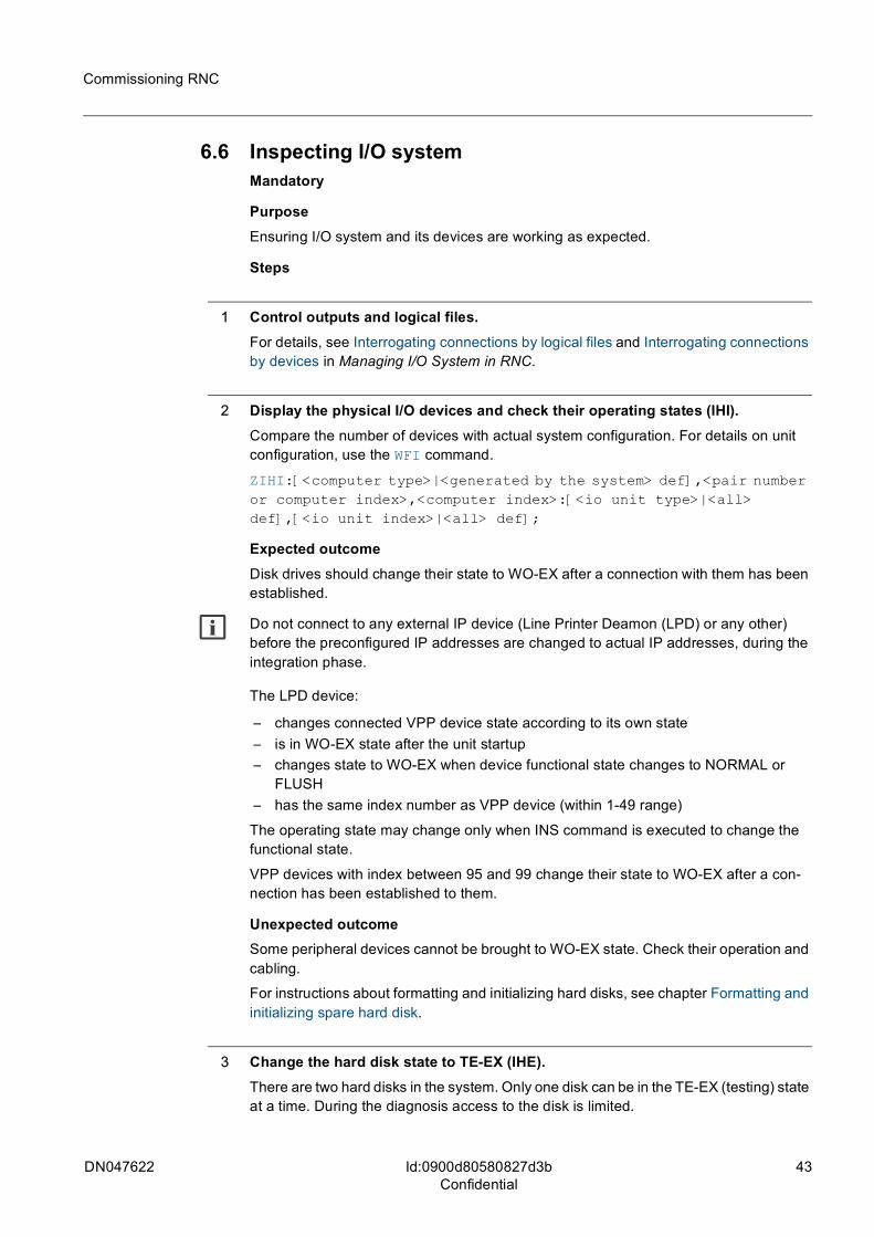
6.6 Inspecting I/O systemMandatory
PurposeEnsuring I/O system and its devices are working as expected.
Steps
1 Control outputs and logical files.For details, see Interrogating connections by logical files and Interrogating connections by devices in Managing I/O System in RNC.
2 Display the physical I/O devices and check their operating states (IHI).Compare the number of devices with actual system configuration. For details on unit configuration, use the WFI command.
ZIHI:[<computer type>|<generated by the system> def],<pair number or computer index>,<computer index>:[<io unit type>|<all> def],[<io unit index>|<all> def];
Expected outcomeDisk drives should change their state to WO-EX after a connection with them has been established.
g Do not connect to any external IP device (Line Printer Deamon (LPD) or any other) before the preconfigured IP addresses are changed to actual IP addresses, during the integration phase.
The LPD device:
– changes connected VPP device state according to its own state– is in WO-EX state after the unit startup– changes state to WO-EX when device functional state changes to NORMAL or
FLUSH– has the same index number as VPP device (within 1-49 range)
The operating state may change only when INS command is executed to change the functional state.
VPP devices with index between 95 and 99 change their state to WO-EX after a con-nection has been established to them.
Unexpected outcomeSome peripheral devices cannot be brought to WO-EX state. Check their operation and cabling.
For instructions about formatting and initializing hard disks, see chapter Formatting and initializing spare hard disk.
3 Change the hard disk state to TE-EX (IHE).There are two hard disks in the system. Only one disk can be in the TE-EX (testing) state at a time. During the diagnosis access to the disk is limited.
44 DN047622
Commissioning RNC
Id:0900d80580827d3bConfidential
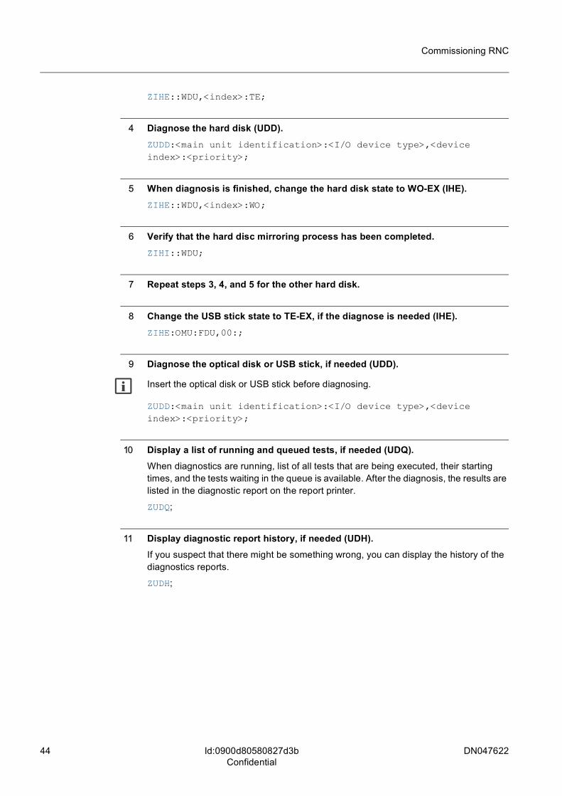
ZIHE::WDU,<index>:TE;
4 Diagnose the hard disk (UDD).ZUDD:<main unit identification>:<I/O device type>,<device index>:<priority>;
5 When diagnosis is finished, change the hard disk state to WO-EX (IHE).ZIHE::WDU,<index>:WO;
6 Verify that the hard disc mirroring process has been completed.ZIHI::WDU;
7 Repeat steps 3, 4, and 5 for the other hard disk.
8 Change the USB stick state to TE-EX, if the diagnose is needed (IHE). ZIHE:OMU:FDU,00:;
9 Diagnose the optical disk or USB stick, if needed (UDD).
g Insert the optical disk or USB stick before diagnosing.
ZUDD:<main unit identification>:<I/O device type>,<device index>:<priority>;
10 Display a list of running and queued tests, if needed (UDQ).When diagnostics are running, list of all tests that are being executed, their starting times, and the tests waiting in the queue is available. After the diagnosis, the results are listed in the diagnostic report on the report printer.
ZUDQ;
11 Display diagnostic report history, if needed (UDH).If you suspect that there might be something wrong, you can display the history of the diagnostics reports.
ZUDH;
DN047622 45
Commissioning RNC
Id:0900d80580827da6Confidential
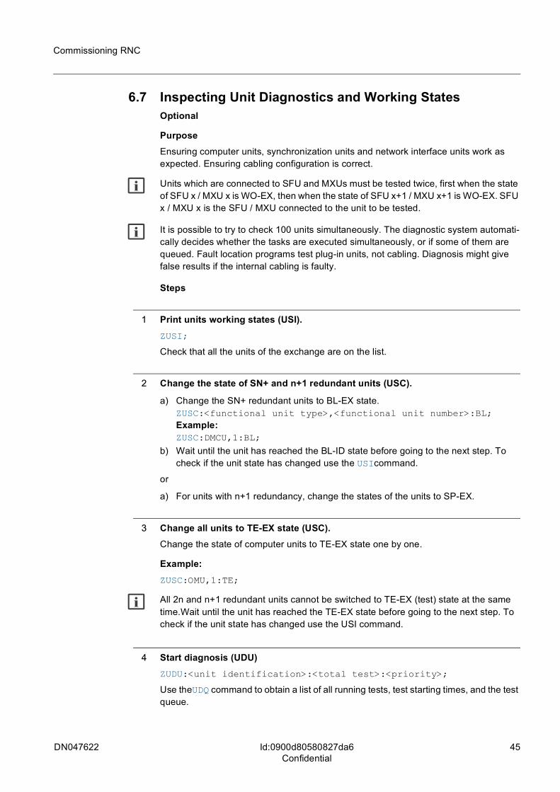
6.7 Inspecting Unit Diagnostics and Working StatesOptional
PurposeEnsuring computer units, synchronization units and network interface units work as expected. Ensuring cabling configuration is correct.
g Units which are connected to SFU and MXUs must be tested twice, first when the state of SFU x / MXU x is WO-EX, then when the state of SFU x+1 / MXU x+1 is WO-EX. SFU x / MXU x is the SFU / MXU connected to the unit to be tested.
g It is possible to try to check 100 units simultaneously. The diagnostic system automati-cally decides whether the tasks are executed simultaneously, or if some of them are queued. Fault location programs test plug-in units, not cabling. Diagnosis might give false results if the internal cabling is faulty.
Steps
1 Print units working states (USI).ZUSI;
Check that all the units of the exchange are on the list.
2 Change the state of SN+ and n+1 redundant units (USC).
a) Change the SN+ redundant units to BL-EX state.ZUSC:<functional unit type>,<functional unit number>:BL; Example: ZUSC:DMCU,1:BL;
b) Wait until the unit has reached the BL-ID state before going to the next step. To check if the unit state has changed use the USIcommand.
or
a) For units with n+1 redundancy, change the states of the units to SP-EX.
3 Change all units to TE-EX state (USC).Change the state of computer units to TE-EX state one by one.
Example: ZUSC:OMU,1:TE;
g All 2n and n+1 redundant units cannot be switched to TE-EX (test) state at the same time.Wait until the unit has reached the TE-EX state before going to the next step. To check if the unit state has changed use the USI command.
4 Start diagnosis (UDU)ZUDU:<unit identification>:<total test>:<priority>;
Use theUDQ command to obtain a list of all running tests, test starting times, and the test queue.
46 DN047622
Commissioning RNC
Id:0900d80580827da6Confidential
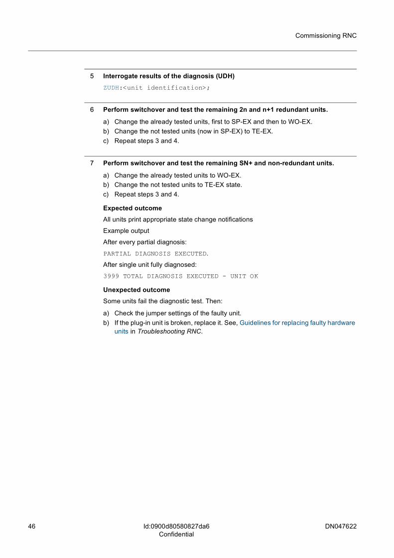
5 Interrogate results of the diagnosis (UDH)ZUDH:<unit identification>;
6 Perform switchover and test the remaining 2n and n+1 redundant units.
a) Change the already tested units, first to SP-EX and then to WO-EX.b) Change the not tested units (now in SP-EX) to TE-EX.c) Repeat steps 3 and 4.
7 Perform switchover and test the remaining SN+ and non-redundant units.
a) Change the already tested units to WO-EX.b) Change the not tested units to TE-EX state.c) Repeat steps 3 and 4.
Expected outcomeAll units print appropriate state change notifications
Example output
After every partial diagnosis:
PARTIAL DIAGNOSIS EXECUTED.
After single unit fully diagnosed:
3999 TOTAL DIAGNOSIS EXECUTED - UNIT OK
Unexpected outcomeSome units fail the diagnostic test. Then:
a) Check the jumper settings of the faulty unit.b) If the plug-in unit is broken, replace it. See, Guidelines for replacing faulty hardware
units in Troubleshooting RNC.
DN047622 47
Commissioning RNC
Id:0900d8058083f7e5Confidential
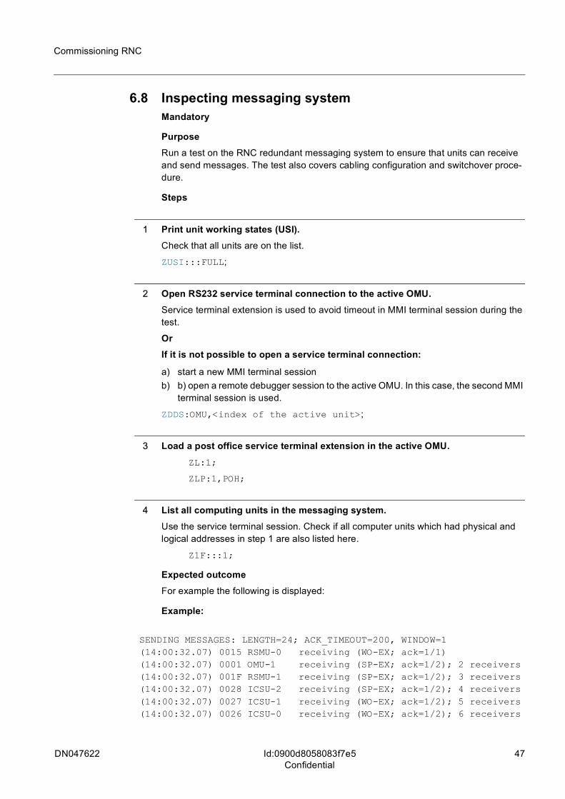
6.8 Inspecting messaging systemMandatory
PurposeRun a test on the RNC redundant messaging system to ensure that units can receive and send messages. The test also covers cabling configuration and switchover proce-dure.
Steps
1 Print unit working states (USI).Check that all units are on the list.
ZUSI:::FULL;
2 Open RS232 service terminal connection to the active OMU.Service terminal extension is used to avoid timeout in MMI terminal session during the test.
OrIf it is not possible to open a service terminal connection:
a) start a new MMI terminal session b) b) open a remote debugger session to the active OMU. In this case, the second MMI
terminal session is used.
ZDDS:OMU,<index of the active unit>;
3 Load a post office service terminal extension in the active OMU.ZL:1;
ZLP:1,POH;
4 List all computing units in the messaging system.Use the service terminal session. Check if all computer units which had physical and logical addresses in step 1 are also listed here.
Z1F:::1;
Expected outcomeFor example the following is displayed:
Example:
SENDING MESSAGES: LENGTH=24; ACK_TIMEOUT=200, WINDOW=1(14:00:32.07) 0015 RSMU-0 receiving (WO-EX; ack=1/1)(14:00:32.07) 0001 OMU-1 receiving (SP-EX; ack=1/2); 2 receivers(14:00:32.07) 001F RSMU-1 receiving (SP-EX; ack=1/2); 3 receivers(14:00:32.07) 0028 ICSU-2 receiving (SP-EX; ack=1/2); 4 receivers(14:00:32.07) 0027 ICSU-1 receiving (WO-EX; ack=1/2); 5 receivers(14:00:32.07) 0026 ICSU-0 receiving (WO-EX; ack=1/2); 6 receivers
48 DN047622
Commissioning RNC
Id:0900d8058083f7e5Confidential
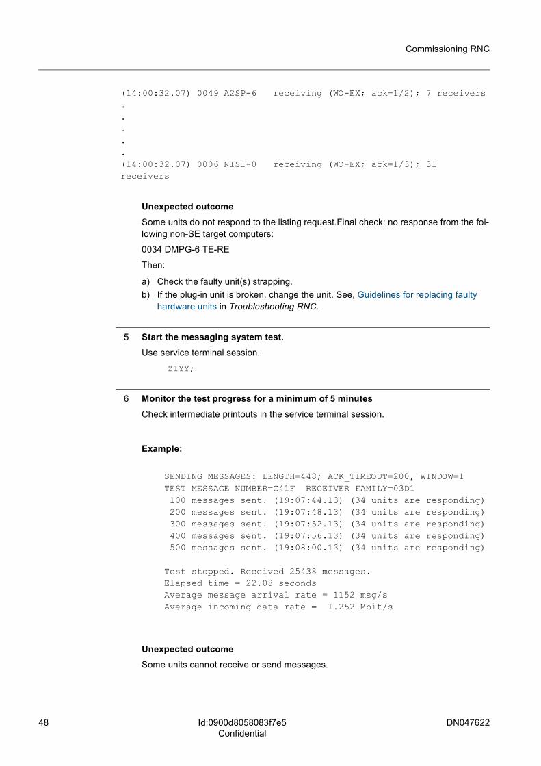
(14:00:32.07) 0049 A2SP-6 receiving (WO-EX; ack=1/2); 7 receivers.....(14:00:32.07) 0006 NIS1-0 receiving (WO-EX; ack=1/3); 31 receivers
Unexpected outcomeSome units do not respond to the listing request.Final check: no response from the fol-lowing non-SE target computers:
0034 DMPG-6 TE-RE
Then:
a) Check the faulty unit(s) strapping.b) If the plug-in unit is broken, change the unit. See, Guidelines for replacing faulty
hardware units in Troubleshooting RNC.
5 Start the messaging system test.Use service terminal session.
Z1YY;
6 Monitor the test progress for a minimum of 5 minutesCheck intermediate printouts in the service terminal session.
Example:
SENDING MESSAGES: LENGTH=448; ACK_TIMEOUT=200, WINDOW=1TEST MESSAGE NUMBER=C41F RECEIVER FAMILY=03D1 100 messages sent. (19:07:44.13) (34 units are responding) 200 messages sent. (19:07:48.13) (34 units are responding) 300 messages sent. (19:07:52.13) (34 units are responding) 400 messages sent. (19:07:56.13) (34 units are responding) 500 messages sent. (19:08:00.13) (34 units are responding)
Test stopped. Received 25438 messages.Elapsed time = 22.08 secondsAverage message arrival rate = 1152 msg/sAverage incoming data rate = 1.252 Mbit/s
Unexpected outcomeSome units cannot receive or send messages.
DN047622 49
Commissioning RNC
Id:0900d8058083f7e5Confidential
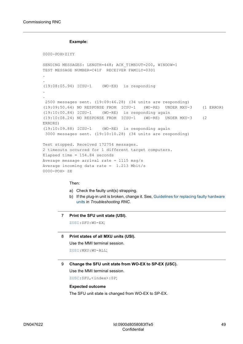
Example:
0000-POH>Z1YY
SENDING MESSAGES: LENGTH=448; ACK_TIMEOUT=200, WINDOW=1TEST MESSAGE NUMBER=C41F RECEIVER FAMILY=03D1..(19:08:05.94) ICSU-1 (WO-EX) is responding.. 2500 messages sent. (19:09:46.28) (34 units are responding)(19:09:50.64) NO RESPONSE FROM ICSU-1 (WO-RE) UNDER MXU-3 (1 ERROR)(19:10:00.84) ICSU-1 (WO-RE) is responding again(19:10:08.24) NO RESPONSE FROM ICSU-1 (WO-RE) UNDER MXU-3 (2 ERRORS)(19:10:09.88) ICSU-1 (WO-RE) is responding again 3000 messages sent. (19:10:10.28) (34 units are responding)
Test stopped. Received 172754 messages.2 timeouts occurred for 1 different target computers.Elapsed time = 154.84 secondsAverage message arrival rate = 1115 msg/sAverage incoming data rate = 1.213 Mbit/s0000-POH> ZE
Then:
a) Check the faulty unit(s) strapping.b) If the plug-in unit is broken, change it. See, Guidelines for replacing faulty hardware
units in Troubleshooting RNC.
7 Print the SFU unit state (USI).ZUSI:SFU:WO-EX;
8 Print states of all MXU units (USI).Use the MMI terminal session.
ZUSI:MXU:WO-ALL;
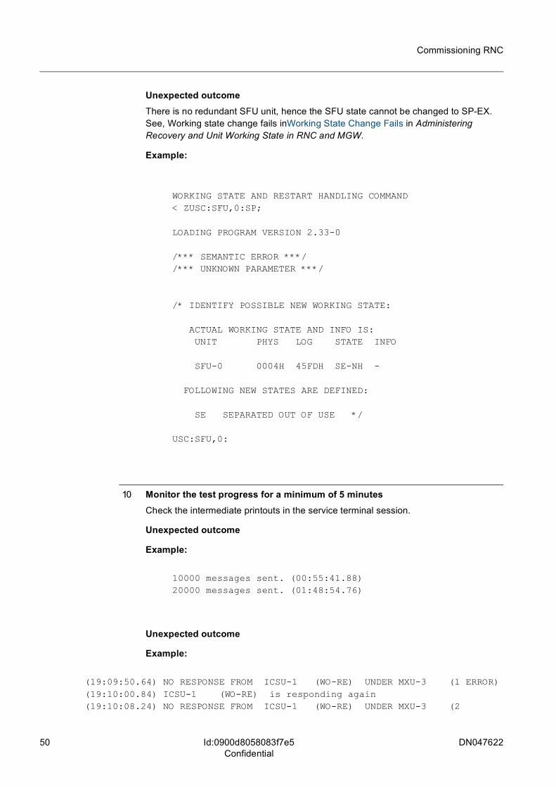
9 Change the SFU unit state from WO-EX to SP-EX (USC).Use the MMI terminal session.
ZUSC:SFU,<index>:SP;
Expected outcomeThe SFU unit state is changed from WO-EX to SP-EX.
50 DN047622
Commissioning RNC
Id:0900d8058083f7e5Confidential
Unexpected outcomeThere is no redundant SFU unit, hence the SFU state cannot be changed to SP-EX. See, Working state change fails inWorking State Change Fails in Administering Recovery and Unit Working State in RNC and MGW.
Example:
WORKING STATE AND RESTART HANDLING COMMAND < ZUSC:SFU,0:SP;
LOADING PROGRAM VERSION 2.33-0
/*** SEMANTIC ERROR ***/ /*** UNKNOWN PARAMETER ***/
/* IDENTIFY POSSIBLE NEW WORKING STATE:
ACTUAL WORKING STATE AND INFO IS: UNIT PHYS LOG STATE INFO
SFU-0 0004H 45FDH SE-NH -
FOLLOWING NEW STATES ARE DEFINED:
SE SEPARATED OUT OF USE */
USC:SFU,0:
10 Monitor the test progress for a minimum of 5 minutesCheck the intermediate printouts in the service terminal session.
Unexpected outcome
Example:
10000 messages sent. (00:55:41.88)20000 messages sent. (01:48:54.76)
Unexpected outcome
Example:
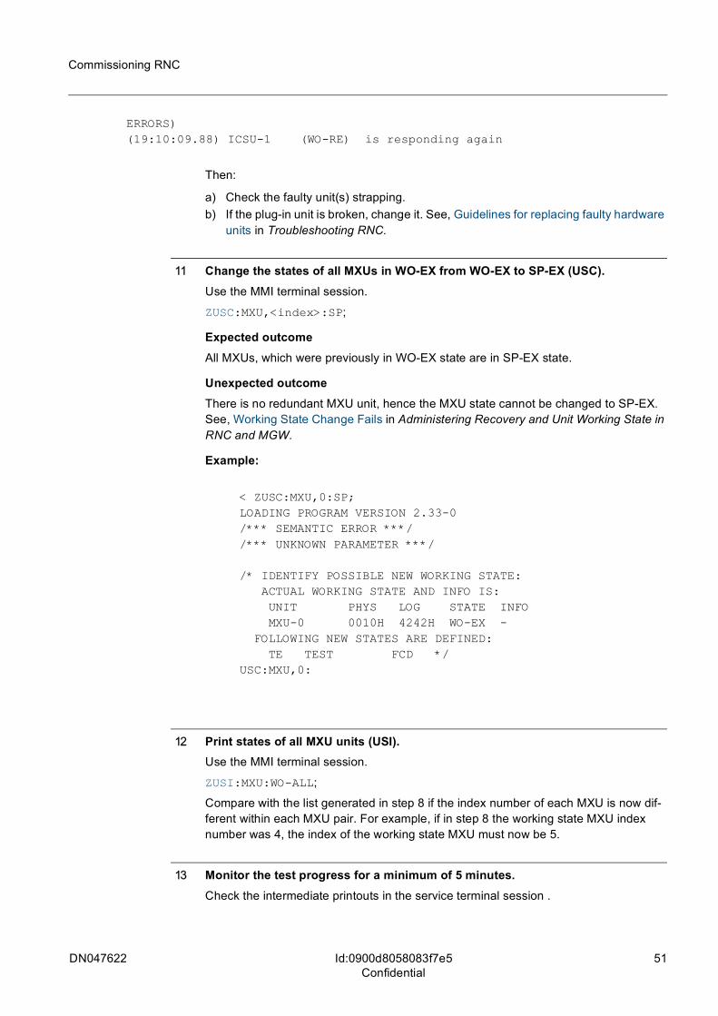
(19:09:50.64) NO RESPONSE FROM ICSU-1 (WO-RE) UNDER MXU-3 (1 ERROR)(19:10:00.84) ICSU-1 (WO-RE) is responding again(19:10:08.24) NO RESPONSE FROM ICSU-1 (WO-RE) UNDER MXU-3 (2
DN047622 51
Commissioning RNC
Id:0900d8058083f7e5Confidential
ERRORS)(19:10:09.88) ICSU-1 (WO-RE) is responding again
Then:
a) Check the faulty unit(s) strapping.b) If the plug-in unit is broken, change it. See, Guidelines for replacing faulty hardware
units in Troubleshooting RNC.
11 Change the states of all MXUs in WO-EX from WO-EX to SP-EX (USC).Use the MMI terminal session.
ZUSC:MXU,<index>:SP;
Expected outcomeAll MXUs, which were previously in WO-EX state are in SP-EX state.
Unexpected outcomeThere is no redundant MXU unit, hence the MXU state cannot be changed to SP-EX. See, Working State Change Fails in Administering Recovery and Unit Working State in RNC and MGW.
Example:
< ZUSC:MXU,0:SP;LOADING PROGRAM VERSION 2.33-0/*** SEMANTIC ERROR ***/ /*** UNKNOWN PARAMETER ***/
/* IDENTIFY POSSIBLE NEW WORKING STATE: ACTUAL WORKING STATE AND INFO IS: UNIT PHYS LOG STATE INFO MXU-0 0010H 4242H WO-EX - FOLLOWING NEW STATES ARE DEFINED: TE TEST FCD */USC:MXU,0:
12 Print states of all MXU units (USI).Use the MMI terminal session.
ZUSI:MXU:WO-ALL;
Compare with the list generated in step 8 if the index number of each MXU is now dif-ferent within each MXU pair. For example, if in step 8 the working state MXU index number was 4, the index of the working state MXU must now be 5.
13 Monitor the test progress for a minimum of 5 minutes.Check the intermediate printouts in the service terminal session .
52 DN047622
Commissioning RNC
Id:0900d8058083f7e5Confidential
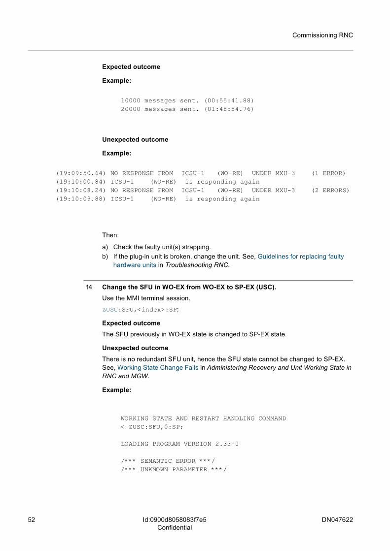
Expected outcome
Example:
10000 messages sent. (00:55:41.88)20000 messages sent. (01:48:54.76)
Unexpected outcome
Example:
(19:09:50.64) NO RESPONSE FROM ICSU-1 (WO-RE) UNDER MXU-3 (1 ERROR)(19:10:00.84) ICSU-1 (WO-RE) is responding again(19:10:08.24) NO RESPONSE FROM ICSU-1 (WO-RE) UNDER MXU-3 (2 ERRORS)(19:10:09.88) ICSU-1 (WO-RE) is responding again
Then:
a) Check the faulty unit(s) strapping.b) If the plug-in unit is broken, change the unit. See, Guidelines for replacing faulty
hardware units in Troubleshooting RNC.
14 Change the SFU in WO-EX from WO-EX to SP-EX (USC).Use the MMI terminal session.
ZUSC:SFU,<index>:SP;
Expected outcomeThe SFU previously in WO-EX state is changed to SP-EX state.
Unexpected outcomeThere is no redundant SFU unit, hence the SFU state cannot be changed to SP-EX. See, Working State Change Fails in Administering Recovery and Unit Working State in RNC and MGW.
Example:
WORKING STATE AND RESTART HANDLING COMMAND < ZUSC:SFU,0:SP;
LOADING PROGRAM VERSION 2.33-0
/*** SEMANTIC ERROR ***/ /*** UNKNOWN PARAMETER ***/
DN047622 53
Commissioning RNC
Id:0900d8058083f7e5Confidential
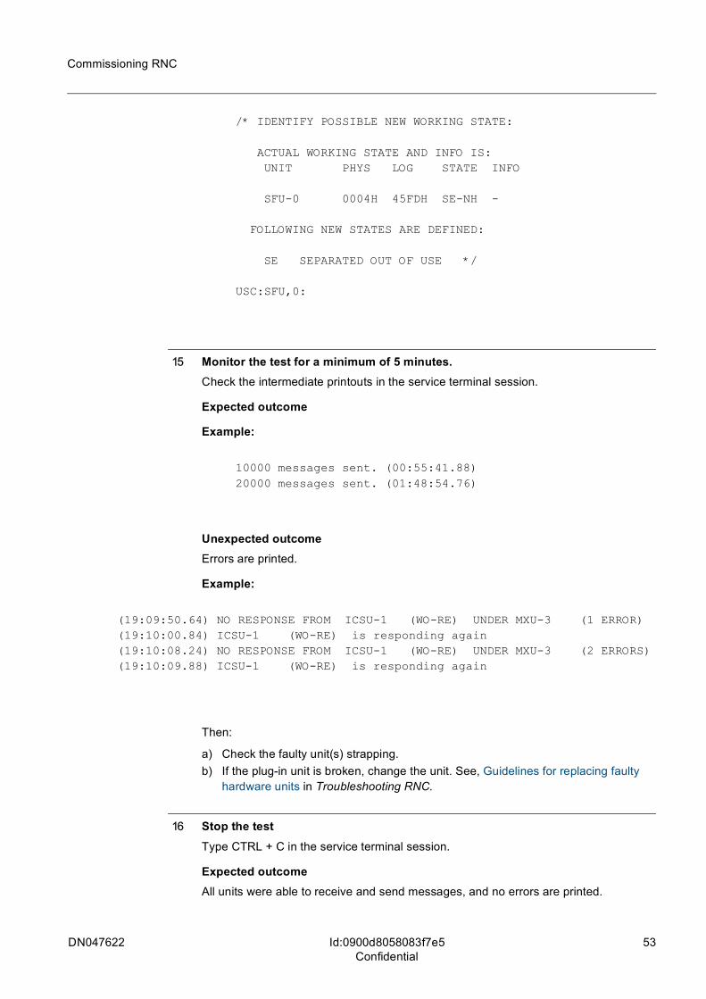
/* IDENTIFY POSSIBLE NEW WORKING STATE:
ACTUAL WORKING STATE AND INFO IS: UNIT PHYS LOG STATE INFO
SFU-0 0004H 45FDH SE-NH -
FOLLOWING NEW STATES ARE DEFINED:
SE SEPARATED OUT OF USE */
USC:SFU,0:
15 Monitor the test for a minimum of 5 minutes.Check the intermediate printouts in the service terminal session.
Expected outcome
Example:
10000 messages sent. (00:55:41.88)20000 messages sent. (01:48:54.76)
Unexpected outcomeErrors are printed.
Example:
(19:09:50.64) NO RESPONSE FROM ICSU-1 (WO-RE) UNDER MXU-3 (1 ERROR)(19:10:00.84) ICSU-1 (WO-RE) is responding again(19:10:08.24) NO RESPONSE FROM ICSU-1 (WO-RE) UNDER MXU-3 (2 ERRORS)(19:10:09.88) ICSU-1 (WO-RE) is responding again
Then:
a) Check the faulty unit(s) strapping.b) If the plug-in unit is broken, change the unit. See, Guidelines for replacing faulty
hardware units in Troubleshooting RNC.
16 Stop the testType CTRL + C in the service terminal session.
Expected outcomeAll units were able to receive and send messages, and no errors are printed.
54 DN047622
Commissioning RNC
Id:0900d8058083f7e5Confidential
Example:
Test stopped. Sent 83672 and received 5494038 messages.Elapsed time = 190.50 secondsAverage message arrival rate = 28840 msg/s Average incoming data rate = 11.074 Mbit/s
Unexpected outcomeSome units were unable to receive or send messages.
Example:
Final check: no response from the following non-SE target computers:0034 DMPG-6 TE-RE
Then:
a) Check the faulty unit(s) strapping.b) If the plug-in unit is broken, change the unit. See, Guidelines for replacing faulty
hardware units in Troubleshooting RNC.c) Run the test again.
DN047622 55
Commissioning RNC Inspecting synchronization system
Id:0900d80580828472Confidential
7 Inspecting synchronization systemMandatory
PurposeEnsuring synchronization system is working as expected.
Steps
1 Check the synchronization cabling connecting the system to Primary Reference Clock (PRC)
a) External timing:Reference signal can be selected from: – "2.048 Mbit– "2.048 MHz– "64K+8K– "T1 mode– "1.544 MHz sine wave– "E1 with CRC framing mode– "E1 with CAS framing mode– "T1 with SF framing mode – "T1 with ESF framing modeExternal timing outputs:– "2.048 MHz– E1– "T1External timing can be connected with external devices, like another network element or BITS (Building Integrated Timing Supply). CPSY/-A/-B or CPSAL/-B panel must be equipped with an external device, if external timing is to be used.
b) Line timing:System clock can be synchronized to SDH network by signal detection on the incoming STM-1 line.Each synchronization unit has three timing inputs that are con-nected by cabling to three different network interface plug-in units. On each interface unit one STM-1 port is selected to give timing. This configuration provides at least three possible timing inputs from the upper network level. Line timing is also sup-ported on E1/T1/JT1 interfaces. Default units are described in Cable Lists. To change default cabling, follow the instructions in step 3.
2 Change external timing interface (if necessary)
– "BNC IN, RJ 45 OUT – "RJ 45 IN, BNC OUT – "RJ 45 IN, RJ 45 OUT
See, Cabinet Interfaces and External Cables of MGW and RNC and Cable Lists.
56 DN047622
Commissioning RNC
Id:0900d80580828472Confidential
Inspecting synchronization system
3 Change line timing cabling (if necessary)Cable Lists show the default pre-installed, and optional line timing cable positions. If line timing cables need to be changed, refer to, Replacing Plug-in Units, and Hardware Con-figuration Management The cables are long enough to connect to any interface unit in any cabinet.
a) Identify the synchronization cable to be removedb) Check if the involved interface units (for example NPS1(P)) are in SE-NH state.
See Taking a Unit Out of Use in Administering Recovery and Unit Working State in RNC and MGW. Do it for:– "unit from which the cabling is being removed – "unit to which the cabling is about to be connected
c) Delete the synchronization cable from the equipment database (WFT)ZWFT;
d) Select new cable location and route it accordingly.
e) Connect the cable to the Z-pack connector, and close the locking latchf) Create the synchronization cable into the equipment database (WFS)
ZWFS;g) Take the units back into use
See Taking Unit Back Into Use in Administering Recovery and Unit Working State in RNC and MGW. Do it for:– "unit from which the cabling was removed – "unit to which the cabling was connected
4 Check SSM values for external references and synchronization (DYI).The possible values are between 0 and 15.
ZDYI:<identification of information>,<identification of references>;
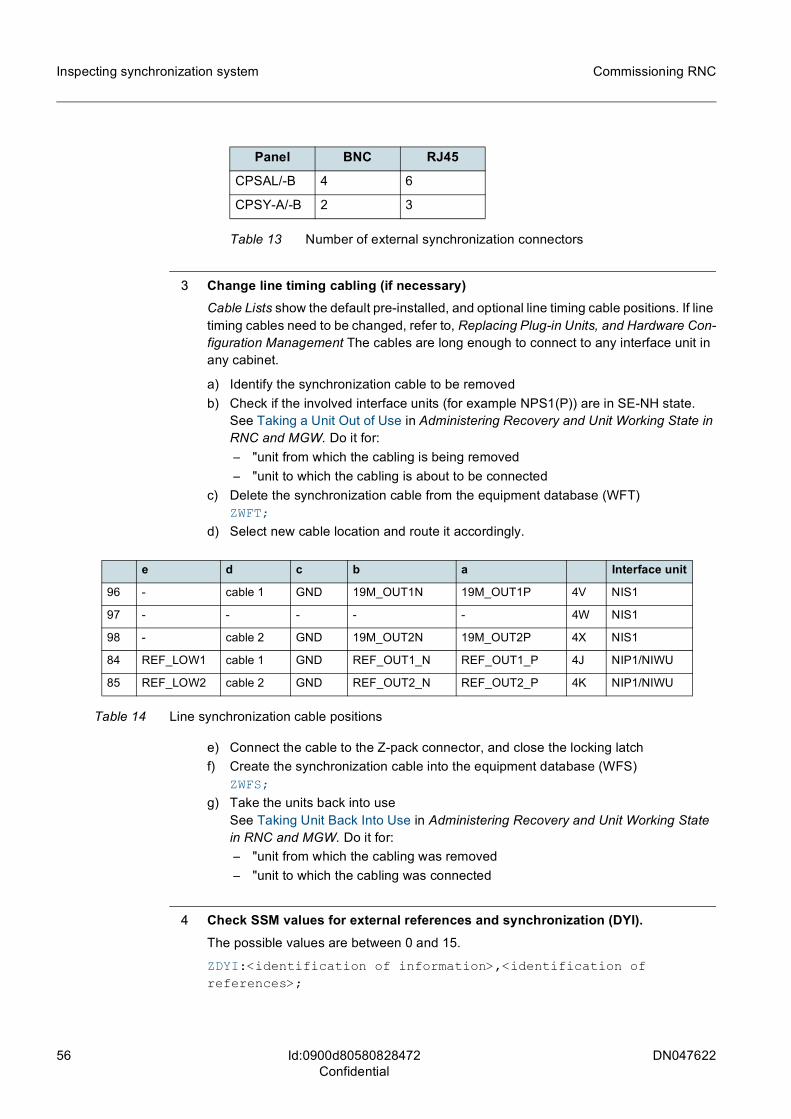
Panel BNC RJ45
CPSAL/-B 4 6
CPSY-A/-B 2 3
Table 13 Number of external synchronization connectors
e d c b a Interface unit
96 - cable 1 GND 19M_OUT1N 19M_OUT1P 4V NIS1
97 - - - - - 4W NIS1
98 - cable 2 GND 19M_OUT2N 19M_OUT2P 4X NIS1
84 REF_LOW1 cable 1 GND REF_OUT1_N REF_OUT1_P 4J NIP1/NIWU
85 REF_LOW2 cable 2 GND REF_OUT2_N REF_OUT2_P 4K NIP1/NIWU
Table 14 Line synchronization cable positions
DN047622 57
Commissioning RNC Inspecting synchronization system
Id:0900d80580828472Confidential
5 Change SSM generations if needed (DYK).ZDYI:SSMGEN;
6 Change SSM generations if neededZDYK:<synchronization reference>,<reference index>:<SSM generation>;
7 Check available references (DYI).ZDYI;
Expected outcomeSuitable synchronization reference is printed.
g When the WTR timer is running, reference status is "NOK". WTR time must expire before the reference can be used. If the WTR time timer is off, the reference is taken into use immediately after its status has changed to "OK ". has expired. The WTR time:
– "starts when the reference is lost – "varies from 1 to 12 minutes– "is 5 minutes by default– "can be changed with the DYL command (SET parameter) – "can be turned off (SET = 0)
8 Check the synchronization references parameters (priority and Synchronization Status Message) (DYI).ZDYI;
9 Change the WTR-timer values of synchronization references, if needed.ZDYL:<synchronization reference>,<reference index>,<action value>;
10 Control general synchronization system settings (DYR).ZDYR:<command identification>,<command action>;
This command can:
– "reset the references switching type – "set special configuration– "cut the outgoing external reference– "include or remove SSM value as selection criterion
When system clocks are the best reference, SSM value can be disregarded as a crite-rion. By default, the SSM and priority values are taken into account when the references are ordered.
The connected reference is ready to be used as system clock once all of the following conditions are met:
58 DN047622
Commissioning RNC
Id:0900d80580828472Confidential
Inspecting synchronization system
– "reference parameter values were entered– "PRI parameter value is other than "X"– "reference status is "OK"
11 Check the outgoing references (DYP).ZDYP;
12 Set outgoing synchronization if it has not been set (DYE)
g Framing mode for outgoing PDH reference must allow the SSM values to be written into the frame. See, Configuring PDH for TDM transport and Configuring PDH for ATM Transport in Integrating RNC.
ZDYE:<synchronization reference>,<reference index>...:ACT=<action>;
13 Check system clock operating modes (DYI).ZDYI;
14 Change the operating modes if needed (DYT).ZDYT:MODE=<operation mode>;
DN047622 59
Commissioning RNC Configuring VDS device
Id:0900d80580828cc9Confidential
8 Configuring VDS deviceMandatory
PurposeEnable the use of Virtual Data Storing Device (VDS). VDS transfers data, such as sta-tistical reports, from a network element to OMS. Additionally, VDS can transfer any data to a post-processing system if the counterpart application supports FTP.
Before you startEstablish TCP/IP connection between the exchange and postprocessing system.
Postprocessing system must have a VDS device counterpart capable of:
• "reading data files • "reading the control information • "writing data to control files
Steps
1 Define disk files parameters: size, number, skipping mode and compression mode (IFF).Take into account storing needs, desired amount of free space and transfer rate.
ZIFF:<unit>:<application>:SIZE=<disk file size>,AMO=<disk file amount>,COMP=<compression mode>,SKIP=<skipping mode>,OVERW=<overwrite mode>;
2 Connect the desired logical file to the VDS device (IIS).ZIIS:<system name>,<destination unit>:<logical file name>,<logical file type>:<current object identification>:<new object identification>;
3 Set alarm limits for the file group (IFA).There are two definable alarm limits for each VDS device. Namely: a limit at which the alarm is set (alarm limit), and a limit at which the alarm is cancelled (cancel limit).
ZIFA:<unit>:<application>:<alarm mode>:<first alarm limit>,<cancel first alarm>:<second alarm limit>,<cancel second alarm>;
4 Set time control for closing the VDS device data file (IFT).Close the disk file of a given application in a given unit before setting its time control.Tim-eouts allow defining:
• "time interval after which the VDS device closes a file • "specific time at which the VDS device closes a file
5 Back up the VDS deviceUse a mass memory device, and spare logical files to back up the VDS device. See:
60 DN047622
Commissioning RNC
Id:0900d80580828cc9Confidential
Configuring VDS device
– Backing up with redundant logical file– Backing up with standby redundant logical file– Backing up with group standby redundant logical file
in Managing I/O System in RNC.
DN047622 61
Commissioning RNC Verifying OMS system startup
Id:0900d80580829de6Confidential
9 Verifying OMS system startup
9.1 Verifying OMS BIOS system timeMandatory
PurposeEnsuring the OMS BIOS system has correct time settings. Note that on USB installation OMS BIOS must be in UTC/GMT time (United Kingdoms time).
Steps
1 Verify time.#date
Expected outcomeThe printout should contain current UTC/GMT time.
2 If time is wrong change it.#date MMDDHHMMCCYY
Example:#date 010713152008
sets system time to January 7th, 1:15pm in the year 2008.
62 DN047622
Commissioning RNC
Id:0900d80580828ce3Confidential
9.2 Testing TCP/IP connections for OMSMandatory
PurposeVerification of TCP/IP links between:
– ESA24/ESA40 OMS functional unit connected to ESA24/ESA40 (for integrated OMS only)
– OMS and the RNC (to check RNC SW level compatibility)
For integrated OMS and other integrated devices connected to the ESA24/ESA40 switch must be in place during the test.
Default OMS IP address is 192.168.1.5. PC subnet mask must match this IP address during the test. PC must have Element Manager installed.
Steps
1 Ping the OMS IP addressPing the IP address that the server is connected to from the operating system, including switches, router, and other devices. Note that the ESA24/ESA40 switch does not reply to ping.
Expected outcomeThere is a response from every unit.
DN047622 63
Commissioning RNC
Id:0900d80580828d0aConfidential
9.3 Testing OMS software startupOptional
PurposeEnsuring OMS: startup, operation tests and shutdown are successful.
Before you startYou need to have a standalone OMS, or OMS functional unit.
Steps
1 Login to OMS using SSH.Type the default IP: 192.168.1.5, login (Nemuadmin), and password (nemuuser).
2 Wait a few minutes to allow services to start.
64 DN047622
Commissioning RNC
Id:0900d80580828d2aConfidential
9.4 Testing Element Manager applicationsOptional
PurposeEnsuring the Element Manager applications work correctly. Note that it is recommended to change the password for the Nemuadmin and its current password.
Before you startYou need to have a standalone OMS, or OMS functional unit, and a PC, or laptop.
Steps
1 Install Application Launcher (EM client).
a) Open an internet browser on your laptop.b) Enter the OMS server IP address in the browser address field.c) Click the Install Application Launcher link and follow the instructions.
2 Start Application Launcher and log into Element Manager.
a) Go to Start > Programs > Nokia Siemens Networks > Application Launcher Client 2 > Application Launcher Client
b) Type in the OMS server IP address, login (Nemuadmin), and password (nemuuser).
3 Start and close each Element Manager application.
4 Check the master-syslog for Application Launcher-related errors#egrep -v "info CLA|warning CLA|notice CLA" /var/log/master-syslog
Expected outcomeMaster-syslog does not contain any error messages after the test. OMS server Element Manager applications work correctly.
DN047622 65
Commissioning RNC
Id:0900d80580828df0Confidential
9.5 Testing secure Element Manager MMI windowMandatory
PurposeEnsuring the Secure MMI Window application works correctly. Ensuring connections between OMS (the running OS) and both OMU units are reliable. State of the OMU that has been tested must be WO-EX.
Steps
1 Start Application Launcher and log into Element Manager.
a) Go to Programs > Nokia Siemens Networks > Application Launcher Client 2 > Application Launcher Client.
b) Type in the OMS server IP address, login (Nemuadmin), and password (nemuuser).
2 Open Secure MMI Window (double-click the icon).
Expected outcomeSecure MMI Window starts and logs into the NE.
Expected outcomeIf secure MMI Window can not start, follow the procedure:
a) Activate SSH server feature ZW7M:FEA=1306:0N;
b) Create RSA and DSA keysZI2K:<public key's name>,<private key's name>:<key type(RSA/DSA)>:<key size>;
c) Enable SSH serverZI2S:IPV4STATE=ON,IPV4PORT=22:IPV6STATE=OFF:RSAKEY=<private RSA key's name>,DSAKEY=<private DSA key's name>:60;
3 Give MML commands to test the application.
4 Make a switchover to OMU
5 Give MML commands to test the application
6 Log out from Application Launcher
7 Check the master-syslog for Application Launcher-related error messages#egrep -v "info CLA|warning CLA|notice CLA" /var/log/master-syslog.
66 DN047622
Commissioning RNC
Id:0900d80580828df0Confidential
Expected outcomeOMS Secure MMI Window application works correctly, connection between OMS and both OMUs can be established, and the mastersyslog does not contain any errors after the test.
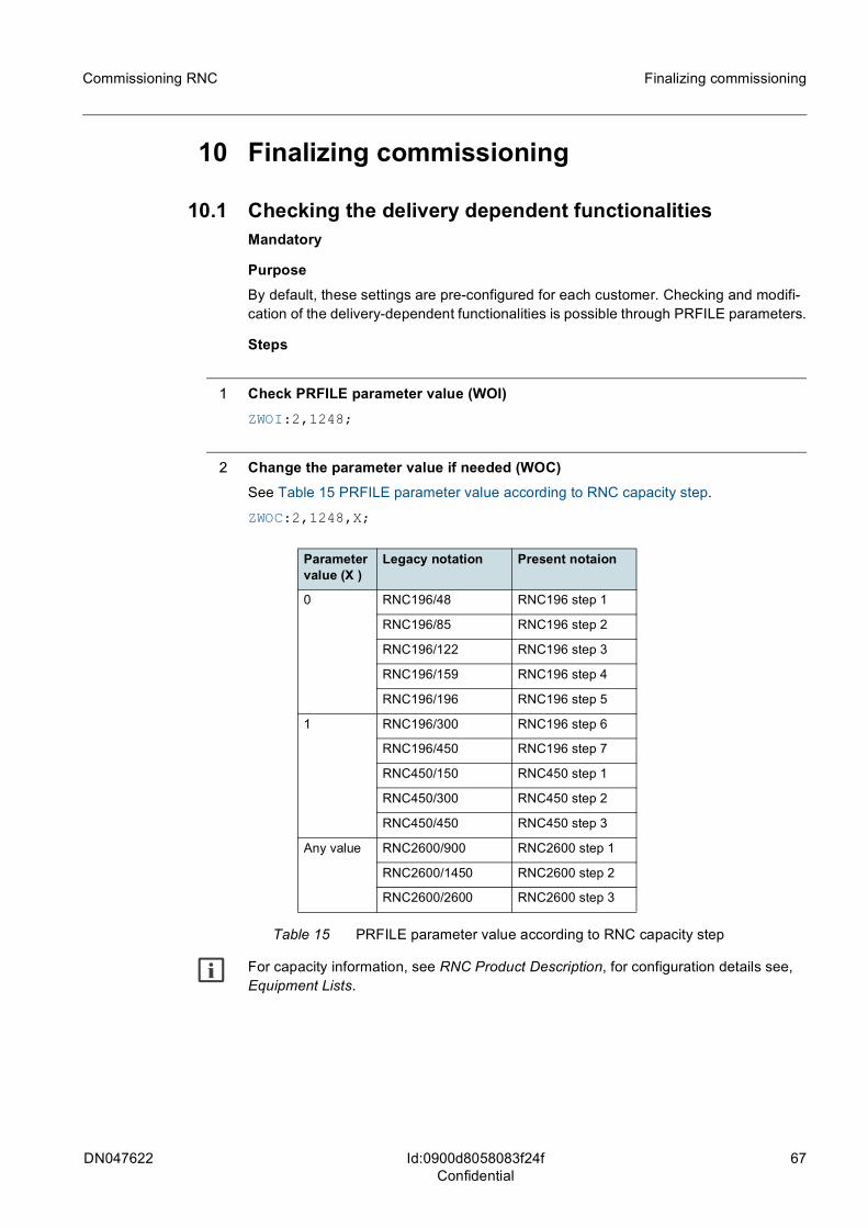
DN047622 67
Commissioning RNC Finalizing commissioning
Id:0900d8058083f24fConfidential
10 Finalizing commissioning
10.1 Checking the delivery dependent functionalitiesMandatory
PurposeBy default, these settings are pre-configured for each customer. Checking and modifi-cation of the delivery-dependent functionalities is possible through PRFILE parameters.
Steps
1 Check PRFILE parameter value (WOI)ZWOI:2,1248;
2 Change the parameter value if needed (WOC)See Table 15 PRFILE parameter value according to RNC capacity step.
ZWOC:2,1248,X;
g For capacity information, see RNC Product Description, for configuration details see, Equipment Lists.
Parameter value (X )
Legacy notation Present notaion
0 RNC196/48 RNC196 step 1
RNC196/85 RNC196 step 2
RNC196/122 RNC196 step 3
RNC196/159 RNC196 step 4
RNC196/196 RNC196 step 5
1 RNC196/300 RNC196 step 6
RNC196/450 RNC196 step 7
RNC450/150 RNC450 step 1
RNC450/300 RNC450 step 2
RNC450/450 RNC450 step 3
Any value RNC2600/900 RNC2600 step 1
RNC2600/1450 RNC2600 step 2
RNC2600/2600 RNC2600 step 3
Table 15 PRFILE parameter value according to RNC capacity step
68 DN047622
Commissioning RNC
Id:0900d8058083f24fConfidential
Finalizing commissioning
3 If PRFILE parameter value has been changed restart the system (USS).
a) Restart takes several minutes. It is highly recommended to perform this task when the traffic load is low.ZUSS::TOT;
b) Set alarm monitoring on and follow-up alarms for 15 min.
Expected outcomeSystem restarts normally and no major alarms raised
DN047622 69
Commissioning RNC
Id:0900d8058082934bConfidential
10.2 Performing the SW updateOptional
PurposeEnsuring network element SW compatibility with the network CD level.
Update of the SW if the preinstalled package is not compatible with the network CD level. See, CD Installation Manual available separately in NOLS.
70 DN047622
Commissioning RNC
Id:0900d8058082934cConfidential
10.3 Safecopying SW build againMandatoryIf any software-related changes had been made during the commissioning, repeat the safecopying procedure. For instructions, see Safecopying FBEMPTY SW build.
DN047622 71
Commissioning RNC
Id:0900d80580829483Confidential
10.4 Reporting item code and serial numberMandatory
PurposeDetailed HW configuration information collection is performed for traceability and inven-tory purposes.
Before you startIt is recommended to use bar code reader HW and SW to collect the serial numbers. It enables more automated transfer of data to NetAct. See, Using Asset Manager Scanner in NetAct Asset Manager documentation. One of the entry points for this data is after commissioning.
If commissioning is a part of product delivery, the ID data is collected with a scanning SW and saved to IM system as a csv file with a certain structure.
Steps
1 Collect the item code and serial number. If commissioning is not performed during the product delivery, the customer determines the process and tools for collecting and storing the ID data. Identification data is stored in the IM system. Depending on the IM system requirements, there are several ways to collect the ID data. Usually units are scanned with a bar code reader.
Expected outcomeSerial number data is created and stored.
72 DN047622
Commissioning RNC
Id:0900d805808294e1Confidential
Appendix A: Formatting and initializing spare hard disk
Appendix A: Formatting and initializing spare hard diskOptional
PurposePreparing a spare WDU unit. In case a hard disk becomes faulty, it can be replaced immediately.
Steps
1 Change the SCSI state to SE (IHE).For disk 0, SCSI bus index is 0, for disk 1 SCSI bus index is 1.
ZIHE::SCSI,<scsi bus index>:SE;
2 Remove the disk from its place
3 Ensure jumpers in the new disk correspond to those in the replaced disk.See, MGW and RNC Jumper Settings of the Plug-in Units and Hard Disk Drives.
4 Put the new unit into its place.
5 Change the SCSI state to TE (IHE).ZIHE::SCSI,<scsi bus index>:TE;
6 Format the new disk, if it's not formatted (IWI). New disks are seldom formatted. Format the disk if you are uncertain whether the disk had been formatted. It takes about 45 minutes for a 73 GB WDU, and considerably longer for drives of higher capacity.
ZIWI::<disk device>;
7 Initialize the formatted WDU, if it's not initialized (IWK). ZIWK::<disk device>;
8 Change the SCSI state to SE (IHE).ZIHE::SCSI,<scsi bus index>:SE;
9 Remove the initialized spare unit disk.
10 Put the old disk back
DN047622 73
Commissioning RNC Appendix A: Formatting and initializing spare hard disk
Id:0900d805808294e1Confidential
11 Change the SCSI state to TE (IHE).ZIHE::SCSI,<scsi bus index>:TE;
12 Change the SCSI state to WO (IHE).ZIHE::SCSI,<scsi bus index>:WO;
74 DN047622
Commissioning RNC
Id:0900d80580842343Confidential
Appendix B: Testing replaced plug-in unit
Appendix B: Testing replaced plug-in unitOptional
PurposeEnsuring that recently replaced unit works as expected. See, Guidelines for Replacing Faulty Hardware Units in Troubleshooting RNC.
Steps
1 Check the unit state (USI).If the unit is in TE state, you can start the test. Otherwise use theUSC command to bring the unit to TE state.
ZUSI;
2 Start the unit test (UDU).ZUDU:<unit identification>:<partial test>:<priority>;
3 Monitor the test progress (UDQ).Make occasional diagnostic system enquiries or check intermediate alarm printer output with partial diagnoses. The test takes from less than a second up to half an hour. Total time depends on the number of test repetitions specified in testing parameter file.
ZUDQ;
Expected outcome The system has registered the unit as operational.
Example outputTOTAL DIAGNOSIS EXECUTED - UNIT OK.
4 Check the test result (UDH).ZUDH:<unit identification>;
Example: Start OMU 0 total test (0 is the unit index).The diagnostic system is checking up to 100 units at a time. when given a diagnosis acti-vation command. UDQ command can be used to check:
– if the system is busy– on the currently active jobs– on queue details
ZUDU:OMU,0;
Example: Start partial test of OMU 1.Test in progress can be interrupted with the UDS command. UDS can be used if results of the current test are not needed at the moment, or if the diagnostics system is not func-tioning properly.
DN047622 75
Commissioning RNC Appendix B: Testing replaced plug-in unit
Id:0900d80580842343Confidential
Example: RAM partial test on OMU 1, as a priority job.ZUDU:OMU,1:RAM:PRI:;
Example: List all functional units registered as broken.Use the command for listing broken units (UDL) to get a list of the functional units in the system that have been registered as broken (BRKN).
If there are broken units, they must be handled one at a time. For testing, transfer the unit to the TE state with the USC command. Then start the diagnostics with the UDU command.
ZUDL;
If a list of broken computer units is needed, use the COMP parameter value.
Handle broken units, one at a time. Use USC command to change the unit to TE state, and diagnose it with UDU command.
76 DN047622
Commissioning RNC
Id:0900d805808299eaConfidential
Appendix C: Troubleshooting functional unit start-up
Appendix C: Troubleshooting functional unit start-upOptional: Perform only if functional units are not in appropriate states.
PurposeTroubleshooting functional unit start-up errors.
Steps
1 Connect a service terminal to OMU and power up the RNC.When the needed software is loaded the service terminal programs should be ready to use. Enter the correct password (default password is SYSTEM).
2 Activate the RCJUUS service terminal extension.RCJUUS enables unit working state monitoring. Note that terminal extension commands are not described in MML reference documentation.During the start-up, OMU should be in WO-EX state.
ZLP:J,RCJ;
3 Monitor the state of the problematic unit.ZJI:ALL;
4 Reset problematic unit.
5 Compare monitoring results to start-up failure descriptions.See, Printouts of Starting Phases in DMX Units, or Printouts of Starting Phases in Chorus Units, depending on a unit type.


![RNC-A SERIES - Bakedeco RNC-210A_Manual.pdf · RNC-90A-R/L 2 RNC-120A-R/L 2 RNC-150A-R/L 3 RNC-180A-R/L 3 RNC-210A-R/L 4 [f] WATERPROOF COVER To prevent the entrance of water, the](https://img.pdfslide.us/doc/110x75/5e680bb313a66779ab666ae1/rnc-a-series-bakedeco-rnc-210amanualpdf-rnc-90a-rl-2-rnc-120a-rl-2-rnc-150a-rl.jpg)


![ZXWR RNC (V3[1].09.30) Commissioning Guide — Integration Manual_R1.0](https://img.pdfslide.us/doc/110x75/577cd1841a28ab9e7894a163/zxwr-rnc-v310930-commissioning-guide-integration-manualr10.jpg)