Embed Size (px)
DESCRIPTION
Using Tomography
Citation preview
312© 2 0 0 6 , C O P Y R I G H T T H E A U T H O R SJ O U R N A L C O M P I L A T I O N © 2 0 0 6 , B L A C K W E L L M U N K S G A A R D
*Chief operating officer, CM Ceramics USA, Mahwah, NJ, USA; Director of biomedical engineering andresearch, Prosthodontics Intermedica, Institute for Facial Esthetics, Fort Washington, PA, USA†Prosthodontist, Prosthodontics Intermedica, Institute for Facial Esthetics, Fort Washington, PA, USA; Staffprosthodontist, VA Medical Center, Philadelphia, PA, USA‡Founder and prosthodontist, Prosthodontics Intermedica, Institute for Facial Esthetics, Fort Washington,PA, USA
Surgical Planning and Prosthesis Construction UsingComputed Tomography, CAD/CAM Technology, and the Internet for Immediate Loading of Dental Implants
STEPHEN F. BALSHI, MBE*
GLENN J . WOLFINGER, DMD, FACP†
THOMAS J . BALSHI, DDS, FACP‡
ABSTRACTThis report describes a protocol that uses computer technology and medical imaging to virtuallyplace anterior and posterior dental implants and to construct a precise surgical template andprosthesis, which is connected at the time of implant placement. This procedure drasticallyreduces patient office time, surgical treatment time, and the degree of post-treatment recovery.Patients with an edentulous arch or a partially edentulous area had a denture with radiopaquemarkers constructed for computed tomography (CT) scans of the appropriate jaw. The CTimages, having acquisition slices of 0.4mm, are transposed in a three-dimensional image-basedprogram for planning and strategic placement of dental implants. After virtual implant place-ment on the computer, the surgical treatment plan is sent to a manufacturing facility for con-struction of the surgical template. The manufactured surgical components and surgical templatearrive on the clinical site. From the surgical template, the dental laboratory retro-engineers themaster cast, articulates it with the opposing dentition based on a duplicate of the scanning den-ture, and creates the prosthesis. Using the surgical template, minimally invasive surgery is per-formed without a flap, and the prosthesis is delivered, achieving immediate functional loading tothe implants. Minor occlusal adjustments are made. The total surgical treatment time required istypically between 30 and 60 minutes. Postoperative symptoms such as pain, swelling, andinflammation are dramatically reduced.
CLINICAL SIGNIFICANCEIdentification of the bone in relationship to the tooth position via three-dimensional CT prior tosurgery allows the clinician to precisely place implants. Computer-aided design/computer-assistedmanufacture technology using the three-dimensional images allows for fabrication of the surgicaltemplate. This is a significant advancement in implant dentistry and promotes interdisciplinaryapproaches to patient treatment. The implant surgeon and restorative dentist can agree uponimplant locations and screw access locations prior to the surgical episode.
(J Esthet Restor Dent 18:312–325, 2006)
DOI 10.1111/j.1708-8240.2006.00029.x
B A L S H I E T A L
V O L U M E 1 8 , N U M B E R 6 , 2 0 0 6 313
I N T R O D U C T I O N
Patient treatment with dentalimplants for oral reconstruction
originally required a two-stageprocess: implant placement itself,followed by abutment connectionmonths later.1 More recently, manystudies have shown comparableosseointegration success rates withimmediate loading of implants,2–28
in some cases minimizing treatmenttime to a single visit.9–12,14,18,19,28
With the use of computed tomogra-phy (CT), computer-aideddesign/computer-assisted manufac-ture (CAD/CAM) technology, andthe Internet, implant dentistry isnow evolving so that surgical treat-ment time is minimized to 1 houror less.
Treatment planning with dentalimplants, typically done with theuse of periapical and panoramicradiographs, has provided sufficientinformation for successful planningin the past; however, there is noclear precision for the placement ofthe implants.29 CT is a medicalimaging technique where imagesare digitally acquired in slices.These slices are then reformattedinto virtually any two-dimensional(2D) or three-dimensional (3D) perspective.30 The ability of thecomputer software to reformatcomputerized axial tomograms into2D and 3D image orientations witha 1:1 replication allows more accurate planning for implantplacement.31
One of the first computer softwareprograms (SimPlant, Materialise,Columbia, MD, USA) that used CTimages had the capability of plan-ning and practicing surgery, but hadno direct way to correlate computerimages to the mouth. OtherCT/CAD/CAM systems offer theability to place implants in the bonewith a developed drill guide; how-ever, they do not provide for animmediate prosthesis.
The 3D computer-assisted technol-ogy is continually expanding. A 3Dimage-based program (NobelGuidepowered by Procera, Nobel BiocareAB, Göteborg, Sweden) for convert-ing CT slices into the 3D space,along with planning and placementof dental implants, was recentlyintroduced. This program allowsthe user to view a selected 3Dimage volume of the patient’s boneand prosthetic appliance as a 3Dscene in which these image-derivedfeatures can be rotated on all axesto provide any desired perspective.Exact virtual representations of theimplants, abutments, and other sur-gical accessories can be insertedinto the 3D scene and positioned inthe precise 3D coordinates that theplanner/clinician deems appropri-ate. These virtual representationscan then be rotated with the image-derived features.
The intention of this article is toreport a thorough explanation ofthe current protocol for interactive
imaging and virtual implant plan-ning. This current protocol hasevolved from the original designtechniques previously reported.32
This article will also discuss thelimitations of the protocol andproper patient selection.
M A T E R I A L S A N D M E T H O D S
Pre-treatment ProceduresThe technique illustrated here for asurgical template and prosthesisconstruction is dependent on thepatient’s existing denture becausethe definitive fixed prosthesis cre-ated from the imaging and proto-typing models is a virtual clone ofthe original denture in a fixedbridge configuration.33 Therefore,all the characteristics of the originaldenture, such as centric and verticalpositions and tooth arrangement,are transferred to the end estheticresult. Other characteristics of theoriginal denture, such as thicknessand extensions of the buccalflanges, are also transferred to thesurgical template. Furthermore, it isimperative to achieve excellent softtissue adaptation so that the surgi-cal template will seat in the mouthas precisely as the original denturedoes.
Once the patient and clinician aresatisfied with the characteristics ofthe original denture, either the orig-inal denture itself or an exact dupli-cate of it is then prepared as thescanning prosthesis. This denture isdotted with radiopaque markers
314
C O M P U T E R T E C H N O L O G Y A N D M E D I C A L I M A G I N G F O R I M M E D I A T E L O A D I N G O F I M P L A N T S
© 2 0 0 6 , C O P Y R I G H T T H E A U T H O R SJ O U R N A L C O M P I L A T I O N © 2 0 0 6 , B L A C K W E L L M U N K S G A A R D
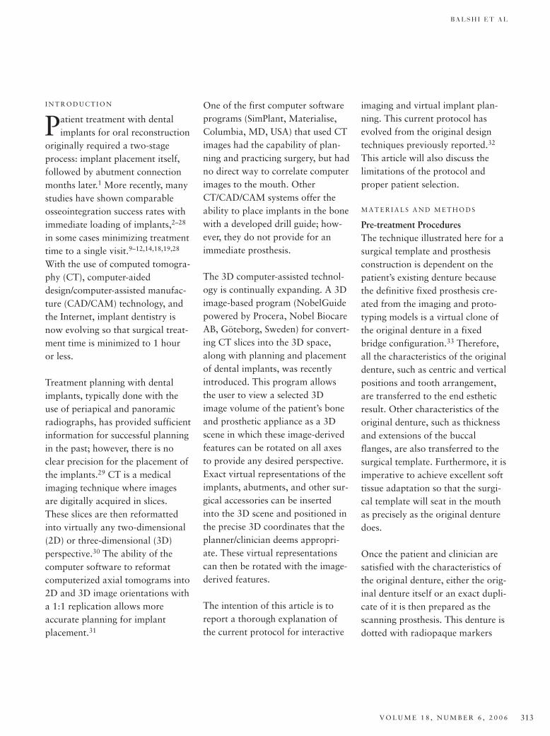
(gutta-percha, Coltene-Whaledent,Cuyahoga Falls, OH, USA) atapproximately 10 to 12 sites at dif-ferent levels in relation to theocclusal plane, with each site about1.5mm in circumference (Figure 1).Vinyl polysiloxane bite registrationpaste (Regisil, Dentsply, Milford,DE, USA) is used to create a centricocclusion index at this stage to sta-bilize the denture and opposingdentition during the CT scanningprocedure.
A double-scan technique is used toacquire the CT data. Either spiralCT scanners or cone-beam CTscanners can be used. The dataacquisition from the CT scan mustbe compatible and adequatelydetailed—slices of about 0.4 mm—to acquire images of the jaws beingtreated. The first scan is performedwith the patient wearing the scan-ning denture and the bite index in place, ensuring the correct
placement of the denture andarrangement of teeth during thescan. The second scan is then per-formed with the scanning denturealone positioned in the CT scannerin the same orientation as it wasduring the first scan. After the CTscanning procedures, the bite indexis preserved for the upcoming labo-ratory procedures.
The computer software uses theradiopaque markers laced in thescanning denture to perform anaccurate fusion of the two separatescans. Resulting from this fusion isan exact representation of thepatient’s bone structure and scan-ning denture in 3D space. At thispoint, the virtual surgical procedurecan be performed.
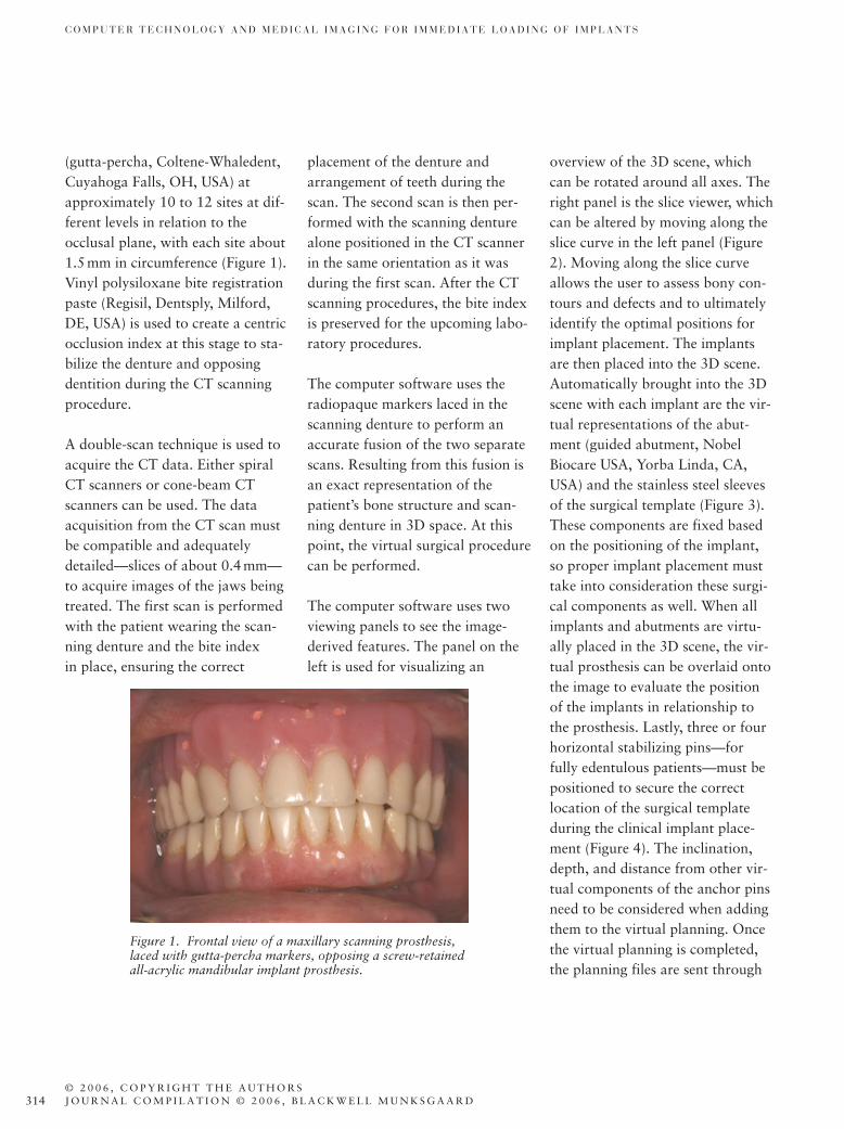
The computer software uses twoviewing panels to see the image-derived features. The panel on theleft is used for visualizing an
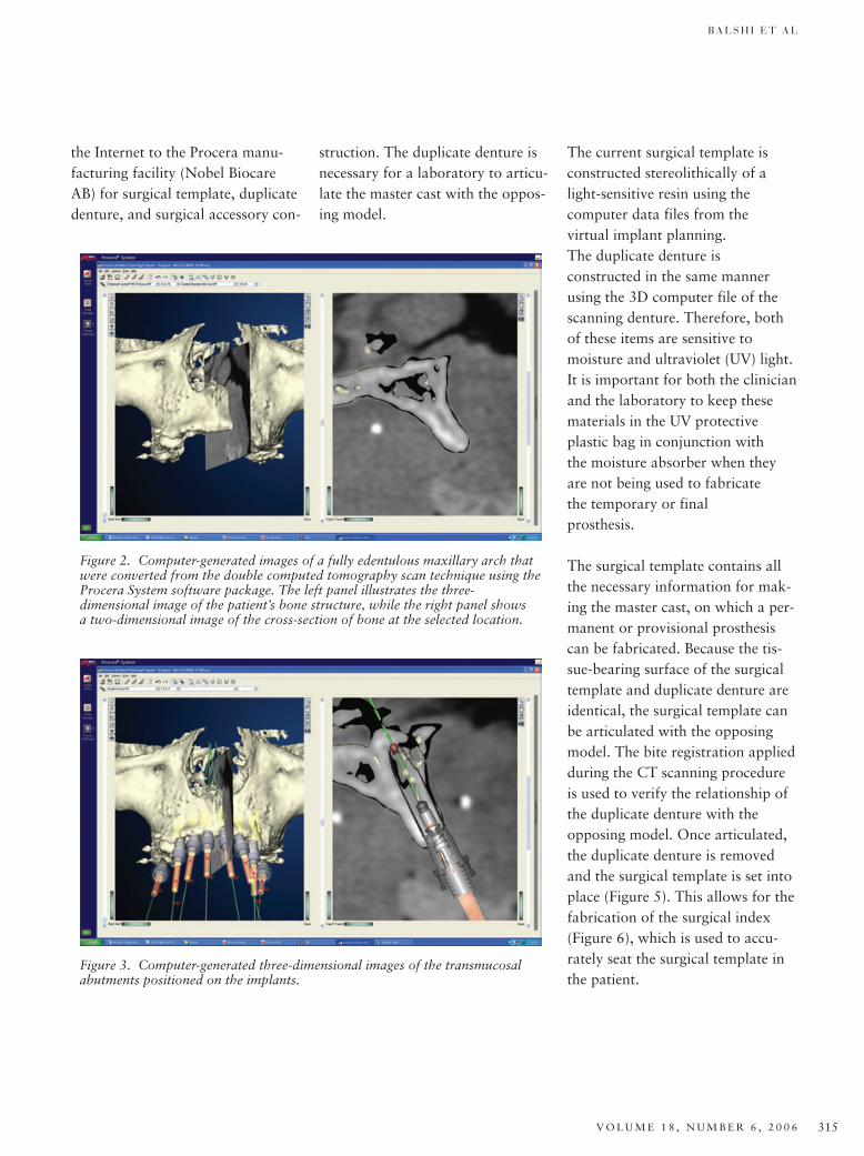
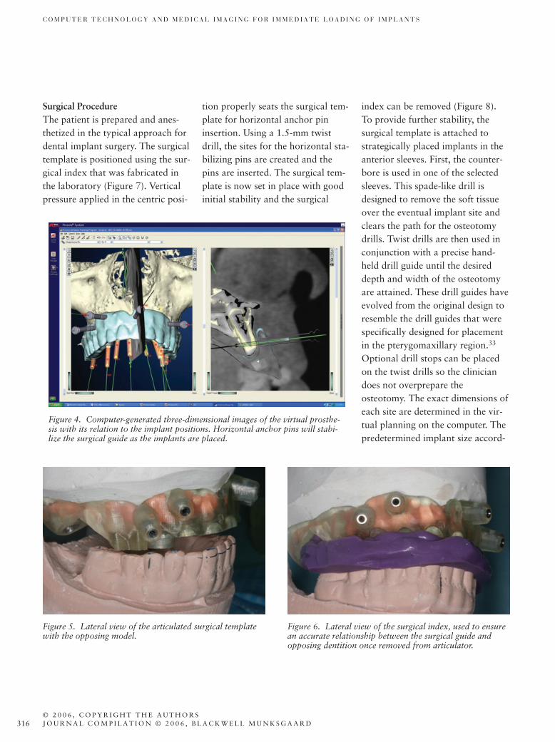
overview of the 3D scene, whichcan be rotated around all axes. Theright panel is the slice viewer, whichcan be altered by moving along theslice curve in the left panel (Figure2). Moving along the slice curveallows the user to assess bony con-tours and defects and to ultimatelyidentify the optimal positions forimplant placement. The implantsare then placed into the 3D scene.Automatically brought into the 3Dscene with each implant are the vir-tual representations of the abut-ment (guided abutment, NobelBiocare USA, Yorba Linda, CA,USA) and the stainless steel sleevesof the surgical template (Figure 3).These components are fixed basedon the positioning of the implant,so proper implant placement musttake into consideration these surgi-cal components as well. When allimplants and abutments are virtu-ally placed in the 3D scene, the vir-tual prosthesis can be overlaid ontothe image to evaluate the positionof the implants in relationship tothe prosthesis. Lastly, three or fourhorizontal stabilizing pins—forfully edentulous patients—must bepositioned to secure the correctlocation of the surgical templateduring the clinical implant place-ment (Figure 4). The inclination,depth, and distance from other vir-tual components of the anchor pinsneed to be considered when addingthem to the virtual planning. Oncethe virtual planning is completed,the planning files are sent through
Figure 1. Frontal view of a maxillary scanning prosthesis,laced with gutta-percha markers, opposing a screw-retainedall-acrylic mandibular implant prosthesis.
B A L S H I E T A L
V O L U M E 1 8 , N U M B E R 6 , 2 0 0 6 315
The current surgical template isconstructed stereolithically of alight-sensitive resin using the computer data files from the virtual implant planning. The duplicate denture is constructed in the same mannerusing the 3D computer file of thescanning denture. Therefore, bothof these items are sensitive to moisture and ultraviolet (UV) light.It is important for both the clinician and the laboratory to keep thesematerials in the UV protective plastic bag in conjunction with the moisture absorber when theyare not being used to fabricate the temporary or final prosthesis.
The surgical template contains allthe necessary information for mak-ing the master cast, on which a per-manent or provisional prosthesiscan be fabricated. Because the tis-sue-bearing surface of the surgicaltemplate and duplicate denture areidentical, the surgical template canbe articulated with the opposingmodel. The bite registration appliedduring the CT scanning procedureis used to verify the relationship ofthe duplicate denture with theopposing model. Once articulated,the duplicate denture is removedand the surgical template is set intoplace (Figure 5). This allows for thefabrication of the surgical index(Figure 6), which is used to accu-rately seat the surgical template inthe patient.
Figure 3. Computer-generated three-dimensional images of the transmucosal abutments positioned on the implants.
Figure 2. Computer-generated images of a fully edentulous maxillary arch thatwere converted from the double computed tomography scan technique using theProcera System software package. The left panel illustrates the three-dimensional image of the patient’s bone structure, while the right panel shows a two-dimensional image of the cross-section of bone at the selected location.
the Internet to the Procera manu-facturing facility (Nobel BiocareAB) for surgical template, duplicatedenture, and surgical accessory con-
struction. The duplicate denture isnecessary for a laboratory to articu-late the master cast with the oppos-ing model.
316
C O M P U T E R T E C H N O L O G Y A N D M E D I C A L I M A G I N G F O R I M M E D I A T E L O A D I N G O F I M P L A N T S
© 2 0 0 6 , C O P Y R I G H T T H E A U T H O R SJ O U R N A L C O M P I L A T I O N © 2 0 0 6 , B L A C K W E L L M U N K S G A A R D
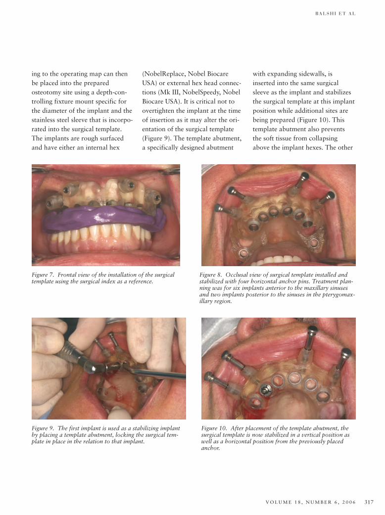
Surgical ProcedureThe patient is prepared and anes-thetized in the typical approach fordental implant surgery. The surgicaltemplate is positioned using the sur-gical index that was fabricated inthe laboratory (Figure 7). Verticalpressure applied in the centric posi-
tion properly seats the surgical tem-plate for horizontal anchor pininsertion. Using a 1.5-mm twistdrill, the sites for the horizontal sta-bilizing pins are created and thepins are inserted. The surgical tem-plate is now set in place with goodinitial stability and the surgical
index can be removed (Figure 8).To provide further stability, the surgical template is attached tostrategically placed implants in theanterior sleeves. First, the counter-bore is used in one of the selectedsleeves. This spade-like drill isdesigned to remove the soft tissueover the eventual implant site andclears the path for the osteotomydrills. Twist drills are then used inconjunction with a precise hand-held drill guide until the desireddepth and width of the osteotomyare attained. These drill guides haveevolved from the original design toresemble the drill guides that werespecifically designed for placementin the pterygomaxillary region.33
Optional drill stops can be placedon the twist drills so the cliniciandoes not overprepare theosteotomy. The exact dimensions ofeach site are determined in the vir-tual planning on the computer. Thepredetermined implant size accord-
Figure 4. Computer-generated three-dimensional images of the virtual prosthe-sis with its relation to the implant positions. Horizontal anchor pins will stabi-lize the surgical guide as the implants are placed.
Figure 5. Lateral view of the articulated surgical templatewith the opposing model.
Figure 6. Lateral view of the surgical index, used to ensurean accurate relationship between the surgical guide andopposing dentition once removed from articulator.
B A L S H I E T A L
V O L U M E 1 8 , N U M B E R 6 , 2 0 0 6 317
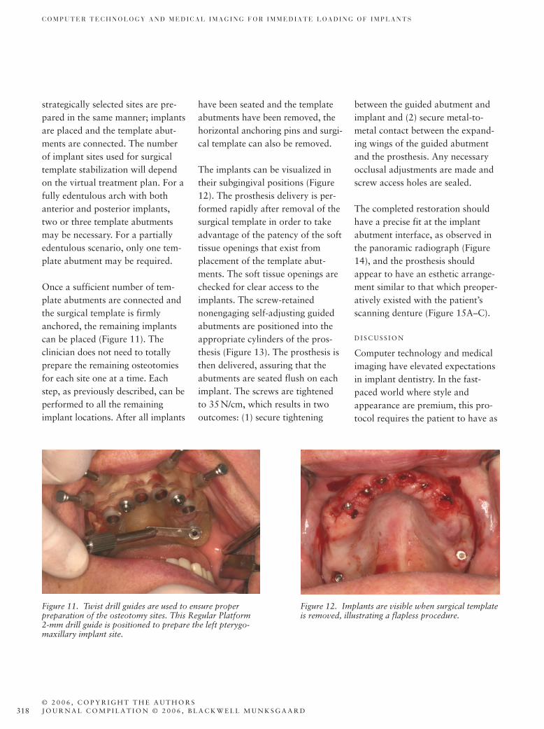
ing to the operating map can thenbe placed into the preparedosteotomy site using a depth-con-trolling fixture mount specific forthe diameter of the implant and thestainless steel sleeve that is incorpo-rated into the surgical template.The implants are rough surfacedand have either an internal hex
(NobelReplace, Nobel BiocareUSA) or external hex head connec-tions (Mk III, NobelSpeedy, NobelBiocare USA). It is critical not toovertighten the implant at the timeof insertion as it may alter the ori-entation of the surgical template(Figure 9). The template abutment,a specifically designed abutment
with expanding sidewalls, isinserted into the same surgicalsleeve as the implant and stabilizesthe surgical template at this implantposition while additional sites arebeing prepared (Figure 10). Thistemplate abutment also preventsthe soft tissue from collapsingabove the implant hexes. The other
Figure 9. The first implant is used as a stabilizing implantby placing a template abutment, locking the surgical tem-plate in place in the relation to that implant.
Figure 10. After placement of the template abutment, thesurgical template is now stabilized in a vertical position aswell as a horizontal position from the previously placedanchor.
Figure 7. Frontal view of the installation of the surgicaltemplate using the surgical index as a reference.
Figure 8. Occlusal view of surgical template installed andstabilized with four horizontal anchor pins. Treatment plan-ning was for six implants anterior to the maxillary sinusesand two implants posterior to the sinuses in the pterygomax-illary region.
318
C O M P U T E R T E C H N O L O G Y A N D M E D I C A L I M A G I N G F O R I M M E D I A T E L O A D I N G O F I M P L A N T S
© 2 0 0 6 , C O P Y R I G H T T H E A U T H O R SJ O U R N A L C O M P I L A T I O N © 2 0 0 6 , B L A C K W E L L M U N K S G A A R D
strategically selected sites are pre-pared in the same manner; implantsare placed and the template abut-ments are connected. The numberof implant sites used for surgicaltemplate stabilization will dependon the virtual treatment plan. For afully edentulous arch with bothanterior and posterior implants,two or three template abutmentsmay be necessary. For a partiallyedentulous scenario, only one tem-plate abutment may be required.
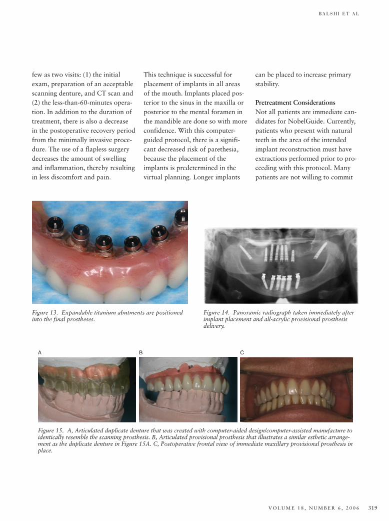
Once a sufficient number of tem-plate abutments are connected andthe surgical template is firmlyanchored, the remaining implantscan be placed (Figure 11). The clinician does not need to totallyprepare the remaining osteotomiesfor each site one at a time. Eachstep, as previously described, can beperformed to all the remainingimplant locations. After all implants
have been seated and the templateabutments have been removed, thehorizontal anchoring pins and surgi-cal template can also be removed.
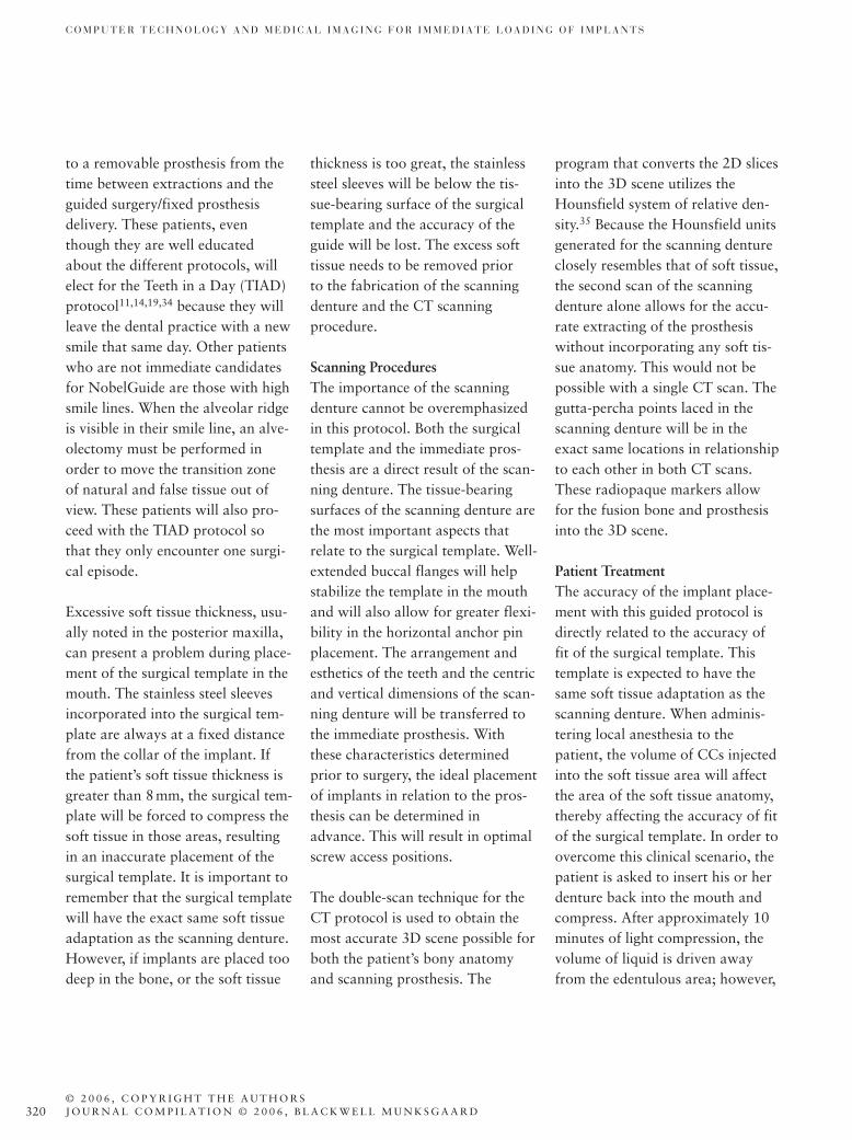
The implants can be visualized intheir subgingival positions (Figure12). The prosthesis delivery is per-formed rapidly after removal of thesurgical template in order to takeadvantage of the patency of the softtissue openings that exist fromplacement of the template abut-ments. The soft tissue openings arechecked for clear access to theimplants. The screw-retainednonengaging self-adjusting guidedabutments are positioned into theappropriate cylinders of the pros-thesis (Figure 13). The prosthesis isthen delivered, assuring that theabutments are seated flush on eachimplant. The screws are tightenedto 35N/cm, which results in twooutcomes: (1) secure tightening
between the guided abutment andimplant and (2) secure metal-to-metal contact between the expand-ing wings of the guided abutmentand the prosthesis. Any necessaryocclusal adjustments are made andscrew access holes are sealed.
The completed restoration shouldhave a precise fit at the implantabutment interface, as observed inthe panoramic radiograph (Figure14), and the prosthesis shouldappear to have an esthetic arrange-ment similar to that which preoper-atively existed with the patient’sscanning denture (Figure 15A–C).
D I S C U S S I O N
Computer technology and medicalimaging have elevated expectationsin implant dentistry. In the fast-paced world where style andappearance are premium, this pro-tocol requires the patient to have as
Figure 11. Twist drill guides are used to ensure properpreparation of the osteotomy sites. This Regular Platform2-mm drill guide is positioned to prepare the left pterygo-maxillary implant site.
Figure 12. Implants are visible when surgical templateis removed, illustrating a flapless procedure.
B A L S H I E T A L
V O L U M E 1 8 , N U M B E R 6 , 2 0 0 6 319
few as two visits: (1) the initialexam, preparation of an acceptablescanning denture, and CT scan and(2) the less-than-60-minutes opera-tion. In addition to the duration oftreatment, there is also a decreasein the postoperative recovery periodfrom the minimally invasive proce-dure. The use of a flapless surgerydecreases the amount of swellingand inflammation, thereby resultingin less discomfort and pain.
Figure 13. Expandable titanium abutments are positionedinto the final prostheses.
Figure 14. Panoramic radiograph taken immediately afterimplant placement and all-acrylic provisional prosthesisdelivery.
A B C
Figure 15. A, Articulated duplicate denture that was created with computer-aided design/computer-assisted manufacture toidentically resemble the scanning prosthesis. B, Articulated provisional prosthesis that illustrates a similar esthetic arrange-ment as the duplicate denture in Figure 15A. C, Postoperative frontal view of immediate maxillary provisional prosthesis inplace.
This technique is successful forplacement of implants in all areasof the mouth. Implants placed pos-terior to the sinus in the maxilla orposterior to the mental foramen inthe mandible are done so with moreconfidence. With this computer-guided protocol, there is a signifi-cant decreased risk of parethesia,because the placement of theimplants is predetermined in thevirtual planning. Longer implants
can be placed to increase primarystability.
Pretreatment ConsiderationsNot all patients are immediate can-didates for NobelGuide. Currently,patients who present with naturalteeth in the area of the intendedimplant reconstruction must haveextractions performed prior to pro-ceeding with this protocol. Manypatients are not willing to commit
320
C O M P U T E R T E C H N O L O G Y A N D M E D I C A L I M A G I N G F O R I M M E D I A T E L O A D I N G O F I M P L A N T S
© 2 0 0 6 , C O P Y R I G H T T H E A U T H O R SJ O U R N A L C O M P I L A T I O N © 2 0 0 6 , B L A C K W E L L M U N K S G A A R D
to a removable prosthesis from thetime between extractions and theguided surgery/fixed prosthesisdelivery. These patients, eventhough they are well educatedabout the different protocols, willelect for the Teeth in a Day (TIAD)protocol11,14,19,34 because they willleave the dental practice with a newsmile that same day. Other patientswho are not immediate candidatesfor NobelGuide are those with highsmile lines. When the alveolar ridgeis visible in their smile line, an alve-olectomy must be performed inorder to move the transition zoneof natural and false tissue out ofview. These patients will also pro-ceed with the TIAD protocol sothat they only encounter one surgi-cal episode.
Excessive soft tissue thickness, usu-ally noted in the posterior maxilla,can present a problem during place-ment of the surgical template in themouth. The stainless steel sleevesincorporated into the surgical tem-plate are always at a fixed distancefrom the collar of the implant. Ifthe patient’s soft tissue thickness isgreater than 8mm, the surgical tem-plate will be forced to compress thesoft tissue in those areas, resultingin an inaccurate placement of thesurgical template. It is important toremember that the surgical templatewill have the exact same soft tissueadaptation as the scanning denture.However, if implants are placed toodeep in the bone, or the soft tissue
thickness is too great, the stainlesssteel sleeves will be below the tis-sue-bearing surface of the surgicaltemplate and the accuracy of theguide will be lost. The excess softtissue needs to be removed prior to the fabrication of the scanningdenture and the CT scanning procedure.
Scanning ProceduresThe importance of the scanningdenture cannot be overemphasizedin this protocol. Both the surgicaltemplate and the immediate pros-thesis are a direct result of the scan-ning denture. The tissue-bearingsurfaces of the scanning denture arethe most important aspects thatrelate to the surgical template. Well-extended buccal flanges will helpstabilize the template in the mouthand will also allow for greater flexi-bility in the horizontal anchor pinplacement. The arrangement andesthetics of the teeth and the centricand vertical dimensions of the scan-ning denture will be transferred tothe immediate prosthesis. Withthese characteristics determinedprior to surgery, the ideal placementof implants in relation to the pros-thesis can be determined inadvance. This will result in optimalscrew access positions.
The double-scan technique for theCT protocol is used to obtain themost accurate 3D scene possible forboth the patient’s bony anatomyand scanning prosthesis. The
program that converts the 2D slicesinto the 3D scene utilizes theHounsfield system of relative den-sity.35 Because the Hounsfield unitsgenerated for the scanning dentureclosely resembles that of soft tissue,the second scan of the scanningdenture alone allows for the accu-rate extracting of the prosthesiswithout incorporating any soft tis-sue anatomy. This would not bepossible with a single CT scan. Thegutta-percha points laced in thescanning denture will be in theexact same locations in relationshipto each other in both CT scans.These radiopaque markers allowfor the fusion bone and prosthesisinto the 3D scene.
Patient TreatmentThe accuracy of the implant place-ment with this guided protocol isdirectly related to the accuracy offit of the surgical template. Thistemplate is expected to have thesame soft tissue adaptation as thescanning denture. When adminis-tering local anesthesia to thepatient, the volume of CCs injectedinto the soft tissue area will affectthe area of the soft tissue anatomy,thereby affecting the accuracy of fitof the surgical template. In order toovercome this clinical scenario, thepatient is asked to insert his or her denture back into the mouth andcompress. After approximately 10minutes of light compression, thevolume of liquid is driven awayfrom the edentulous area; however,
B A L S H I E T A L
V O L U M E 1 8 , N U M B E R 6 , 2 0 0 6 321
the area still remains numb. Thesurgical template can then beinserted into the mouth with thesurgical index and the drilling pro-cedure can begin.
The NobelGuide protocol allowsfor immediate delivery of either aprovisional or definitive restora-tion. The precision of the system, afunction of the CT scanning proce-dure, can be accurate to one hun-dredth of a millimeter (0.01mm).This precision will allow the clini-cian to deliver a definitive restora-tion with a Procera milled titaniumframework if so desired. Thetremendous benefit of delivering thedefinitive prosthesis is that thepatient will receive their “final” setof teeth the same day as the implantplacement and will not be requiredto return for final impression try-ins, among other visits.
The authors of this report suggestthe delivery of an all-acrylic screw-retained provisional prosthesis.Even though the patient isinstructed to accept the functionaland esthetic arrangement of teethbased on the scanning denture priorto surgery, the patient may stillelicit dissatisfaction with the result.With a provisional restoration, it ispossible to adapt to the patient’ssatisfaction; not so with the tita-nium framework. Osseointegrationis also not yet 100% predictable.From research, it is known that themajority of implant failures will
occur in the first months followingimplant placement. If an implantwould fail to integrate, that implantmust be removed and the provi-sional prosthesis can be modified tosplint the remaining integratedimplants. Once osseointegration isnoted both clinically and radi-ographically, a final prostheticreconstruction can be delivered.
If the patient is delivered a provi-sional bridge at the time of surgeryand then a definitive restorationseveral months later, the restorativeclinician should retain the provi-sional prosthesis in storage. If thissame patient several years later pre-sented with a fractured crown, theclinician could simply remove thedefinitive prosthesis and replace itwith the provisional prosthesiswhile laboratory work is beingcompleted to repair the definitiverestoration. Directly going to thedefinitive prosthesis with this pro-tocol eliminates this option for thepatient and clinician.
LimitationsThe majority of the limitations arein the number of patients who areimmediate candidates for theNobelGuide protocol. However,once a patient is deemed acceptablefor the protocol, there are only afew limitations that are not consid-ered in conventional implantsurgery. Because this protocol usesa surgical template for implantplacement, the virtual planning
must consider the proximity of thestainless steel sleeves to oneanother. In other words, implantsare not able to be placed as closetogether as they can be in conven-tional placement techniques. Thereis a minimum requirement of 1.5mm between each stainless steelsurgical sleeve so that the integrityof the surgical template remainsand the template does not fractureduring the drilling procedure.
Because the orientation of theimplant hex is not known until it isphysically in place in the bone, theabutment used for this protocol is anonengaging abutment. At thistime, there is only one abutmentchoice available for each implantplatform in the Procera Software.This abutment is a straight abut-ment. This limits the degree ofdivergency between any twoimplants. Although recent develop-ments have been made for non-engaging angulated abutments,these have not been virtually represented into the computer software at this time.
Future ConsiderationsThe NobelGuide protocol allowsthe clinician to treat patients withdental implants while reducing theamount of bone grafting and sinuslifts procedures. Treatment of theseverely atrophic maxilla by utiliz-ing the zygoma and pterygomaxil-lary regions is a treatment optionfor all patients. While this guided
322
C O M P U T E R T E C H N O L O G Y A N D M E D I C A L I M A G I N G F O R I M M E D I A T E L O A D I N G O F I M P L A N T S
© 2 0 0 6 , C O P Y R I G H T T H E A U T H O R SJ O U R N A L C O M P I L A T I O N © 2 0 0 6 , B L A C K W E L L M U N K S G A A R D
protocol can incorporate the use ofpterygomaxillary implants,33 surgi-cal templates are not manufacturedfor cases with zygoma implants atthis time.
C O N C L U S I O N
Identification of the bony anatomyin relation to the teeth prior tosurgery allows the clinician to placeimplants in areas where theimplant–bone interface can be max-imized and the prosthetic result isoptimized. This is a tremendousadvantage for both the clinicianand the patient. The clinician canprovide a treatment plan thatreduces the operating time, surgicaltrauma, and postoperative recoveryperiod from conventional freehandimplant surgery, yet maintain a pre-cise, stable, and biomechanicallysound outcome. The time savedwith this revolutionary procedure isremarkable. There is no second-stage abutment connection surgery,no need for impressions, and noadditional clinical or laboratoryprocedures. The time for the patientis minimum—a single 1-hour proce-dure versus numerous longer visitsfollowing the traditional implantprotocols. This is a significantadvancement in implant dentistryand prosthodontics and forces aninterdisciplinary approach to thetreatment of patients.
A C K N O W L E D G M E N T S
The authors do not have any finan-cial interest in the companies whose
materials are discussed in this article.
The authors would like to thankthe staff at Prosthodontics Intermedica for their kind and verygentle treatment of the patients;Robert Winkelman and the staff ofFort Washington Dental Laboratoryfor laboratory support; and Chris-tine Raines for her assistance withmanuscript preparation.
R E F E R E N C E S
1. Brånemark P-I, Zarb GA, Albrektsson T,eds. Tissue integrated prosthesis. Osseoin-tegration in clinical dentistry. Chicago(IL): Quintessence Publishing Co.; 1985.
2. Schnitman P, Wohrle P, Rubenstein J.Immediate fixed prostheses supported bytwo-stage threaded implants: methodol-ogy and results. J Oral Implantol1990;16:96–105.
3. Schnitman P, Wohrle P, Rubenstein J, etal. Ten-year results for Brånemarkimplants loaded with fixed prostheses atimplant placement. Int J Oral MaxillofacImplants 1997;12:495–503.
4. Tarnow D, Emtiaz S, Classi A. Immediateloading of threaded implants at stage Isurgery in edentulous arches: ten consec-utive case reports with 1- to 5-year data.Int J Oral Maxillofac Implants1997;12:319–24.
5. Chiapasco M, Gatti C, Rossi E, et al.Implant-retained mandibular overden-tures with immediate loading: a retro-spective multicenter study on 226consecutive cases. Clin Oral Implants Res1997;8:48–57.
6. Brånemark P-I, Engstrand P, Ohrnell L-O, et al. Novum: a new treatment con-cept for rehabilitation of the edentulousmandible. Preliminary results from aprospective clinical follow-up study. ClinImplant Dent Relat Res 1999;1:2–16.
7. Ericsson I, Randow K, Nilner K, Peter-sson A. Early functional loading ofBrånemark dental implants: 5-year clini-cal follow-up study. Clin Oral ImplantsRes 2000;2:70–7.
8. Gatti C, Haefliger W, Chiapasco M.Implant-retained mandibular overden-tures with immediate loading: a prospective study of ITI implants. Int JOral Maxillofac Implants2000;15:383–8.
9. Wolfinger GJ, Balshi TJ, Rangert B.Immediate functional loading of Brånemark system implants in edentulousmandibles: clinical report of the results ofdevelopmental and simplified protocols.Int J Oral Maxillofac Implants2003;18:250–7.
10. Petropoulos VC, Balshi TJ, Balshi SF,Wolfinger GJ. Treatment of a patientwith cleidocranial dysplasia usingosseointegrated implants: a patientreport. Int J Oral Maxillofac Implants2004;19:282–7.
11. Balshi TJ, Wolfinger GJ. A new protocolfor immediate functional loading of den-tal implants. Dent Today2001;20(9):60–5.
12. Balshi T, Wolfinger G. Immediate load-ing of Brånemark implants in edentulousmandibles: a preliminary report. ImplantDent 1997;6(2):83–8.
13. Vidjak F, Zeichner-David M. Immediate-loading dental endosteal implants and theelderly patient. J Calif Dent Assoc2003;31(12):917–24.
14. Balshi TJ, Wolfinger GJ. Immediateplacement and implant loading for expe-dited patient care: a patient report. Int JOral Maxillofac Implants2002;17:587–92.
15. Andersen E, Haanæs HR, Knutsen BM.Immediate loading of single-tooth ITIimplants in the anterior maxilla: aprospective 5-year pilot study. Clin OralImplants Res 2002;13:281–7.
16. Rocci A, Martignonu M, Gottlow J,Rangert B. Immediate function of singleand partial reconstructions in the maxillausing Mk IV fixtures. Appl Osseointegra-tion Res 2001;2(1):22–6.
17. Chatzistavrou M, Felton DA, Cooper LF.Immediate loading of dental implants inpartially edentulous patients: a clinicalreport. J Prosthodont 2003;12:26–9.
18. Balshi TJ, Wolfinger GJ. Immediate load-ing of dental implants in the edentulousmaxilla: case study of a unique protocol.Int J Periodont Rest Dent2003;23:37–45.
B A L S H I E T A L
V O L U M E 1 8 , N U M B E R 6 , 2 0 0 6 323
19. Balshi TJ, Wolfinger GJ. Teeth in a Day®
for the maxilla and mandible: casereport. Clin Implant Dent Relat Res2003;5(1):11–6.
20. Horiuchi K, Uchida H, Yamamoto K,Sugimura M. Immediate loading ofBrånemark system implants followingplacement in edentulous patients: a clini-cal report. Int J Oral Maxillofac Implants2000;15:824–30.
21. Kinsel RP, Lamb RE. Development ofgingival esthetics in the edentulouspatient with immediate loaded, single-stage, implant-supported fixed prosthe-ses: a clinical report. Int J OralMaxillofac Implants 2000;15:711–21.
22. Kosinski TF, Skowronski R Jr. Immediateimplant loading: a case report. J OralImplantol 2002;2:87–91.
23. Radnow K, Ericsson I, Nilner K, et al.Immediate functional loading of Bråne-mark dental implants: an 18-month clini-cal follow-up study. Clin Oral ImplantsRes 1999;10:8–15.
24. Salama H, Rose LF, Salama M, Betts NJ.Immediate loading of bilaterally splintedtitanium root-form implants in fixedprosthodontics—a technique reexamined:two case reports. Int J Periodont RestorDent 1995;15:345–61.
25. Nikellis I, Levi A, Nicolopoulos C. Imme-diate loading of 190 endosseous dentalimplants: a prospective observational
study of 40 patient treatments with up to2-year data. Int J Oral MaxillofacImplants 2004;19:116–23.
26. Olsson M, Urde G, Anderson JB, Sen-nerby L. Early loading of maxillary fixedcross-arch dental prostheses supported bysix or eight oxidized titanium implants:results after 1 year of loading, case series.Clin Implant Dent Relat Res2003;5s1:81–5.
27. Jaffin RA, Kumar A, Berman CL. Imme-diate loading of dental implants in thecompletely edentulous maxilla: a clinicalreport. Int J Oral Maxillofac Implants2004;19:721–30.
28. Balshi SF, Allen FD, Wolfinger GJ, Balshi TJ. A resonance frequency analysis assessment of maxillary andmandibular immediately loaded implants.J Oral Maxillofac Implants2005;20:584–94.
29. Kraut RA. Interative CT diagnostics,planning and preparation for dentalimplants. Implant Dent 1998;7:19–25.
30. Abrahams JJ, Kalyanpur A. Dentalimplants and dental CT software pro-grams. Semin Ultrasound CT MR1995;16:468–86.
31. Benson BW. Presurgical radiographicplanning for dental implants. Oral Maxillofac Surg Clin North Am2001;13:751–61.
32. Parel SM, Triplett RG. Interactive imag-ing for implant planning, placement, andprosthesis construction. J Oral Maxillo-fac Surg 2004;9:41–7.
33. Balshi SF, Wolfinger GJ, Balshi TJ. Surgi-cal planning and prosthesis constructionusing computer technology and medicalimaging for immediate loading ofimplants in the pterygomaxillary region.Int J Periodont Rest Dent2006;26:239–47.
34. Balshi SF, Wolfinger GJ, Balshi TJ. Aprospective study of immediate func-tional loading, following the Teeth in aDayTM protocol: a case series of 55 con-secutive edentulous maxillas. ClinImplant Dent Relat Res 2005;7:24–31.
35. Hounsfield GN. Nobel award address.Computed medical imaging. Med Phys1980;7(4):283–90.
Reprint requests: Stephen F. Balshi, Prostho-dontics Intermedica, 467 Pennsylvania Ave,Suite 201, Fort Washington, PA 19034; Tel.:(215) 646-6334; Fax: (215) 643-1149;email: [email protected]
Portions of this article are reprinted fromBalshi SF, Wolfinger GJ, Balshi TJ. Surgicalplanning and prosthesis construction usingcomputer technology and medical imagingfor immediate loading of implants in thepterygomaxillary region. Int J PeriodontRestor Dent 2006;26(3):239–47 by permis-sion of Quintessence Publishing Co., Inc.
©2006 Blackwell Publishing, Inc.