Embed Size (px)
Citation preview
Title Three-dimensional virtual-reality surgical planning and soft-tissue prediction for orthognathic surgery
Author(s) Xia, J; Ip, HHS; Samman, N; Wong, HTF; Gateno, J; Wang, D;Yeung, RWK; Kot, CSB; Tideman, H
Citation Ieee Transactions On Information Technology In Biomedicine,2001, v. 5 n. 2, p. 97-107
Issued Date 2001
URL http://hdl.handle.net/10722/42610
Rights Creative Commons: Attribution 3.0 Hong Kong License
IEEE TRANSACTIONS ON INFORMATION TECHNOLOGY IN BIOMEDICINE, VOL. 5, NO. 2, JUNE 2001 97
Three-Dimensional Virtual-Reality Surgical Planningand Soft-Tissue Prediction for Orthognathic SurgeryJames Xia, Member, IEEE, Horace H. S. Ip, Member, IEEE, Nabil Samman, Helena T. F. Wong, Jaime Gateno,
Dongfeng Wang, Richie W. K. Yeung, Christy S. B. Kot, and Henk Tideman
Abstract—Complex maxillofacial malformations continue topresent challenges in analysis and correction beyond moderntechnology. The purpose of this paper is to present a virtual-re-ality workbench for surgeons to perform virtual orthognathicsurgical planning and soft-tissue prediction in three dimensions.A resulting surgical planning system, i.e., three-dimensionalvirtual-reality surgical-planning and soft-tissue prediction fororthognathic surgery, consists of four major stages: computedtomography (CT) data post-processing and reconstruction,three-dimensional (3-D) color facial soft-tissue model generation,virtual surgical planning and simulation, soft-tissue-changepreoperative prediction. The surgical planning and simulationare based on a 3-D CT reconstructed bone model, whereas thesoft-tissue prediction is based on color texture-mapped andindividualized facial soft-tissue model. Our approach is ableto provide a quantitative osteotomy-simulated bone model andprediction of postoperative appearance with photorealistic quality.The prediction appearance can be visualized from any arbitraryviewing point using a low-cost personal-computer-based system.This cost-effective solution can be easily adopted in any hospitalfor daily use.
Index Terms—Maxillofacial deformity, orthognathic surgery,soft-tissue-change prediction, three-dimensional surgical planningand simulation, virtual reality.
I. INTRODUCTION
I T IS frequently difficult to make a precise surgical plan tocorrect for complex maxillofacial deformity using conven-
tional methods. Traditional surgical planning for orthognathicsurgery is determined by cephalometric analysis, and clinicaland aesthetic judgment.
Three-dimensional (3-D) studies in medicine started at thebeginning of the 1970’s [1]. The cross-sectional imaging capa-bility of computed tomography (CT) [2] and 3-D reconstructionhave led to a tremendous leap in diagnostic radiology. Althoughcross-sectional slices avoid superimposition of adjacent struc-tures and permit high-resolution details of bone, 3-D rendered
Manuscript received March 28, 2000; revised October 3, 2000. This work wassupported in part by the University of Hong Kong under Committee on Researchand Conference grants.
J. Xia was with the Oral and Maxillofacial Surgery Department, The Uni-versity of Hong Kong, Hong Kong. He is now with the Department of Oral andMaxillofacial Surgery, Dental Branch, University of Texas at Houston, Houston,TX 77030 USA.
H. H. S. Ip, H. T. F. Wong, and C. S. B. Kot are with the Department ofComputer Science, City University of Hong Kong, Kowloon, Hong Kong.
N. Samman, D. Wang, R. W. K. Yeung, and H. Tideman are with the Oral andMaxillofacial Surgery Department, The University of Hong Kong, Hong Kong.
J. Gateno is with the Department of Oral and Maxillofacial Surgery, DentalBranch, University of Texas at Houston, Houston, TX 77030 USA.
Publisher Item Identifier S 1089-7771(01)02028-3.
visualization provides the radiologists and surgeons with readilyrecognizable images of complex anatomic structures. It can ex-actly record and represent the life size and shape of bone forprecise bone surgery planning and simulation.
Orthognathic surgery attempts to reestablish functional andaesthetic anatomy by repositioning displaced bones or bygrafting and recontouring the deformed bone contour. Soft-tissue changes usually accompany these skeletal alterations,but, despite the advance in imaging modalities, the predictionsoft-tissue deformation upon the bone structure change stillposes major challenges to both surgeons and computer scien-tists. Although there are several methods to capture the soft-tissue contours, such as laser scanning [3], Cyberwere [4],the Moiré imaging technique [5], 3-D digitizer [6], and 3-Dphotographic method [7], to quantify bone-soft-tissue relationsand to predict soft-tissue changes remain as open researchproblems.
Surgical planning, postoperative prediction, and visual-ization requires a combination of the knowledge betweenmedicine and computer graphics. With respect to the pointpresented earlier, the purpose of this paper is to present avirtual-reality environment for orthognathic surgical planning.The environment provides facilities for a surgeon to makesurgical plans, to simulate various orthognathic surgicalprocedures as they are routinely performed in an operatingroom, and to predict soft-tissue changes before operation.Furthermore, we present a surgical-planning system, which istermed the three-dimensional virtual-reality surgical-planningand soft-tissue prediction for orthognathic surgery (3DVRSP).The development of the 3DVRSP system is based on ourprevious studies on 3-D color facial-model generation [8],3-D virtual osteotomy [9], and 3-D soft-tissue planning andprediction [10].
II. VRSP OVERVIEW
The virtual-reality workbench 3DVRSP consists of fourmajor functions:
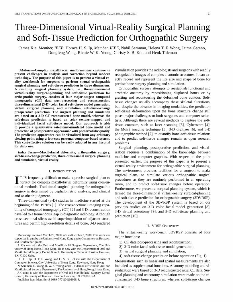
1) CT data post-processing and reconstruction;2) 3-D color facial soft-tissue model generation;3) virtual surgical planning and simulation;4) soft-tissue-change prediction before operation (Fig. 1).
Mensurations such as linear and spatial measurements are alsoincluded as supplemental functions. Anatomy modeling and vi-sualization were based on 3-D reconstructed axial CT data. Sur-gical planning and osteotomy simulation were made on the re-constructed 3-D bone structures, whereas soft-tissue changes
1089–7771/01$10.00 © 2001 IEEE
98 IEEE TRANSACTIONS ON INFORMATION TECHNOLOGY IN BIOMEDICINE, VOL. 5, NO. 2, JUNE 2001
Fig. 1. System overview of 3DVRSP system.
were then predicted on the individualized and color texture-mapped facial soft-tissue model.
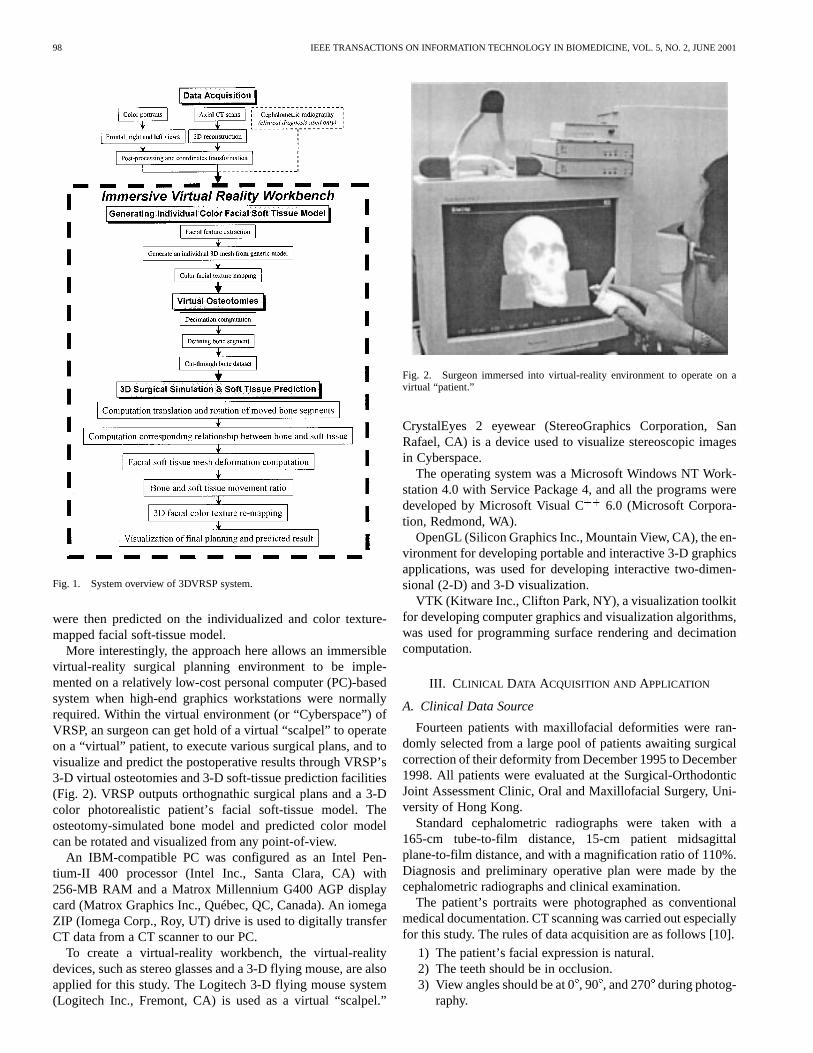
More interestingly, the approach here allows an immersiblevirtual-reality surgical planning environment to be imple-mented on a relatively low-cost personal computer (PC)-basedsystem when high-end graphics workstations were normallyrequired. Within the virtual environment (or “Cyberspace”) ofVRSP, an surgeon can get hold of a virtual “scalpel” to operateon a “virtual” patient, to execute various surgical plans, and tovisualize and predict the postoperative results through VRSP’s3-D virtual osteotomies and 3-D soft-tissue prediction facilities(Fig. 2). VRSP outputs orthognathic surgical plans and a 3-Dcolor photorealistic patient’s facial soft-tissue model. Theosteotomy-simulated bone model and predicted color modelcan be rotated and visualized from any point-of-view.
An IBM-compatible PC was configured as an Intel Pen-tium-II 400 processor (Intel Inc., Santa Clara, CA) with256-MB RAM and a Matrox Millennium G400 AGP displaycard (Matrox Graphics Inc., Québec, QC, Canada). An iomegaZIP (Iomega Corp., Roy, UT) drive is used to digitally transferCT data from a CT scanner to our PC.
To create a virtual-reality workbench, the virtual-realitydevices, such as stereo glasses and a 3-D flying mouse, are alsoapplied for this study. The Logitech 3-D flying mouse system(Logitech Inc., Fremont, CA) is used as a virtual “scalpel.”
Fig. 2. Surgeon immersed into virtual-reality environment to operate on avirtual “patient.”
CrystalEyes 2 eyewear (StereoGraphics Corporation, SanRafael, CA) is a device used to visualize stereoscopic imagesin Cyberspace.
The operating system was a Microsoft Windows NT Work-station 4.0 with Service Package 4, and all the programs weredeveloped by Microsoft Visual C 6.0 (Microsoft Corpora-tion, Redmond, WA).
OpenGL (Silicon Graphics Inc., Mountain View, CA), the en-vironment for developing portable and interactive 3-D graphicsapplications, was used for developing interactive two-dimen-sional (2-D) and 3-D visualization.
VTK (Kitware Inc., Clifton Park, NY), a visualization toolkitfor developing computer graphics and visualization algorithms,was used for programming surface rendering and decimationcomputation.
III. CLINICAL DATA ACQUISITION AND APPLICATION
A. Clinical Data Source
Fourteen patients with maxillofacial deformities were ran-domly selected from a large pool of patients awaiting surgicalcorrection of their deformity from December 1995 to December1998. All patients were evaluated at the Surgical-OrthodonticJoint Assessment Clinic, Oral and Maxillofacial Surgery, Uni-versity of Hong Kong.
Standard cephalometric radiographs were taken with a165-cm tube-to-film distance, 15-cm patient midsagittalplane-to-film distance, and with a magnification ratio of 110%.Diagnosis and preliminary operative plan were made by thecephalometric radiographs and clinical examination.
The patient’s portraits were photographed as conventionalmedical documentation. CT scanning was carried out especiallyfor this study. The rules of data acquisition are as follows [10].
1) The patient’s facial expression is natural.2) The teeth should be in occlusion.3) View angles should be at 0, 90 , and 270during photog-
raphy.
XIA et al.: 3-D VIRTUAL-REALITY SURGICAL PLANNING AND SOFT-TISSUE PREDICTION FOR ORTHOGNATHIC SURGERY 99
4) The corresponding facial organ’s position, i.e., the mouth,should be as similar as possible between CT scanning andphotography.
5) The Frankfort Plane should be parallel to the horizontalplane as close as possible during photography, whereasthe Frankfort Plane of the supine patient need to be ver-tical in relation to the horizontal plane during CT scan-ning.
6) Head and jaw’s movements and facial expressions areprohibited during CT scanning.
7) Both portraits and CT scanning should be taken in thesame period (normally within one week of each other).
B. Color-Portrait Photography
The frontal, right-, and left-side views of the patient’s facein the natural head position were photographed separately bya Medical-Nikkor 120 mm/f4 lens (Nikon Corporation, Tokyo,Japan). The magnification was fixed at 1 : 8 or 1 : 11, dependingon the height of the patient’s head. The central focal axis of thelens was adjusted to remain horizontal during the photographyprocess. The patient’s Frankfort Plane was parallel to the hori-zontal plane. Portraits were then scanned as 24-bit images intothe computer via a Nikon LS-20 film scanner (Nikon Corpora-tion, Tokyo, Japan) and the digitized images were resampled to360 550 pixels each.
C. CT Data Acquisition
All patients were examined by a GE Pace CT Scanner (GEMedical Systems, Waukesha, WI) at the Hong Kong Adven-tist Hospital, Hong Kong, with a thickness of 2.0 mm and orig-inal 512 512 matrix with 16 bits. The display fields of view(FOV) ranged from 21 to 30 cm. CT scanning was performedat 120 KV, 80 mA, and 2.0 s each by 99125 slices, dependingon the height of the patient’s head. The Frankfort Plane of thesupine patient was vertical in relation to the horizontal plane. Arubber band was used to restrict the patient head’s movementduring CT scanning. The 2-D axial slices started from the sub-mandibular region and covered the whole head. All the raw dataof CT scans were digitally transferred from the CT scanner toour PC by an iomega ZIP drive without losing any signal.
IV. M ETHODS
A. Processing of CT Data and 3-D Unique Coordinate System
1) Processing of CT Data:For the true perspective of datavisualization, image-processing techniques were used to ma-nipulate image contents to improve the results of subsequentprocessing and interpretation. The post-processing functions in-cluded: 1) removing undesired objects; 2) masking individualbone structure; and 3) the bone-structure enhancement.
Segmentation was the process of classifying pixels in theimage or volume [11]. Depending on the scene complexity, itcan be one of the most difficult tasks in the visualization process.Interactive segmentation was used if the threshold filter was notable to mask the bone in the CT dataset during the marchingcubes process.
2) 3-D Reconstruction:A volumetric dataset was then pre-pared by using the marching cubes algorithm [12], [13] from the
Fig. 3. 3-D coordinate system transformation.
processed CT raw data. For fast rendering and shading, all thesucceeding operations were based on this volumetric dataset.The original CT slices were discarded in the subsequent pro-cessing.
3) Unique 3-D Coordinate System:The view coordinatesystem represented what was visible to the observer. Theand
coordinates specified location of object in a plane, whereasthe coordinate represented the depth. The original coordinatesin the CT dataset were transformed to the patient’s coordinatesystem, accounting for slight malpositioning of the patientduring the CT scanning [8]–[10].
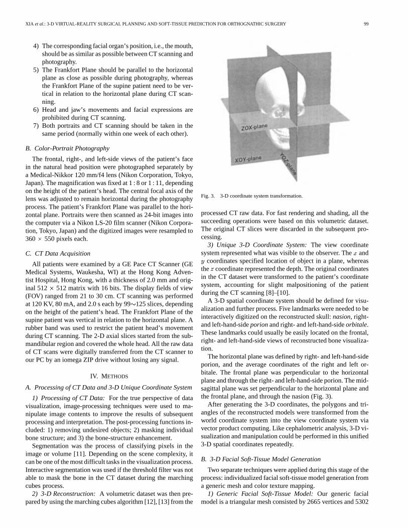
A 3-D spatial coordinate system should be defined for visu-alization and further process. Five landmarks were needed to beinteractively digitized on the reconstructed skull:nasion, right-and left-hand-sideporionand right- and left-hand-sideorbitale.These landmarks could usually be easily located on the frontal,right- and left-hand-side views of reconstructed bone visualiza-tion.
The horizontal plane was defined by right- and left-hand-sideporion, and the average coordinates of the right and left or-bitale. The frontal plane was perpendicular to the horizontalplane and through the right- and left-hand-side porion. The mid-sagittal plane was set perpendicular to the horizontal plane andthe frontal plane, and through the nasion (Fig. 3).
After generating the 3-D coordinates, the polygons and tri-angles of the reconstructed models were transformed from theworld coordinate system into the view coordinate system viavector product computing. Like cephalometric analysis, 3-D vi-sualization and manipulation could be performed in this unified3-D spatial coordinates repeatedly.
B. 3-D Facial Soft-Tissue Model Generation
Two separate techniques were applied during this stage of theprocess: individualized facial soft-tissue model generation froma generic mesh and color texture mapping.
1) Generic Facial Soft-Tissue Model:Our generic facialmodel is a triangular mesh consisted by 2665 vertices and 5302
100 IEEE TRANSACTIONS ON INFORMATION TECHNOLOGY IN BIOMEDICINE, VOL. 5, NO. 2, JUNE 2001
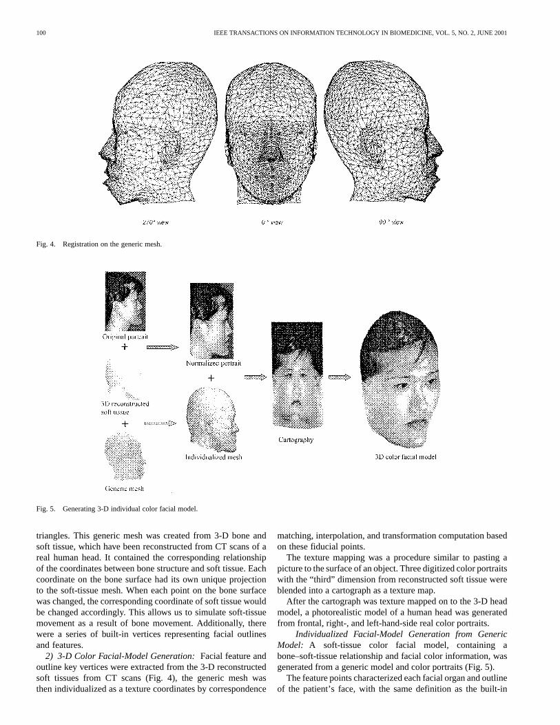
Fig. 4. Registration on the generic mesh.
Fig. 5. Generating 3-D individual color facial model.
triangles. This generic mesh was created from 3-D bone andsoft tissue, which have been reconstructed from CT scans of areal human head. It contained the corresponding relationshipof the coordinates between bone structure and soft tissue. Eachcoordinate on the bone surface had its own unique projectionto the soft-tissue mesh. When each point on the bone surfacewas changed, the corresponding coordinate of soft tissue wouldbe changed accordingly. This allows us to simulate soft-tissuemovement as a result of bone movement. Additionally, therewere a series of built-in vertices representing facial outlinesand features.
2) 3-D Color Facial-Model Generation:Facial feature andoutline key vertices were extracted from the 3-D reconstructedsoft tissues from CT scans (Fig. 4), the generic mesh wasthen individualized as a texture coordinates by correspondence
matching, interpolation, and transformation computation basedon these fiducial points.
The texture mapping was a procedure similar to pasting apicture to the surface of an object. Three digitized color portraitswith the “third” dimension from reconstructed soft tissue wereblended into a cartograph as a texture map.
After the cartograph was texture mapped on to the 3-D headmodel, a photorealistic model of a human head was generatedfrom frontal, right-, and left-hand-side real color portraits.
Individualized Facial-Model Generation from GenericModel: A soft-tissue color facial model, containing abone–soft-tissue relationship and facial color information, wasgenerated from a generic model and color portraits (Fig. 5).
The feature points characterized each facial organ and outlineof the patient’s face, with the same definition as the built-in
XIA et al.: 3-D VIRTUAL-REALITY SURGICAL PLANNING AND SOFT-TISSUE PREDICTION FOR ORTHOGNATHIC SURGERY 101
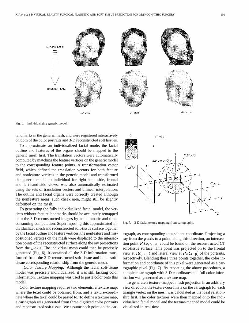
Fig. 6. Individualizing generic model.
landmarks in the generic mesh, and were registered interactivelyon both of the color portraits and 3-D reconstructed soft tissues.
To approximate an individualized facial mode, the facialoutline and features of the organs should be mapped to thegeneric mesh first. The translation vectors were automaticallycomputed by matching the feature vertices on the generic modelto the corresponding feature points. A transformation vectorfield, which defined the translation vectors for both featureand nonfeature vertices in the generic model and transformedthe generic model to individual for right-hand side, frontaland left-hand-side views, was also automatically estimatedusing the sets of translation vectors and bilinear interpolation.The outline and facial organs were correctly created althoughthe nonfeature areas, such cheek area, might still be slightlydeformed on the mesh.
To generating the fully individualized facial model, the ver-tices without feature landmarks should be accurately remappedonto the 3-D reconstructed images by an automatic and time-consuming computation. Superimposing this approximated in-dividualized mesh and reconstructed soft-tissue surface togetherby the facial outline and feature vertices, the nonfeature and mis-positioned vertices on the mesh were displaced to the intersec-tion points of the reconstructed surface along the ray projectionsfrom the -axis. The individual mesh could then be preciselygenerated (Fig. 6). It contained all the 3-D information trans-formed from the 3-D reconstructed soft-tissue and bone–soft-tissue corresponding relationship from the generic mesh.
Color Texture Mapping:Although the facial soft-tissuemodel was precisely individualized, it was still lacking colorinformation. Texture mapping was used to paste color onto thismodel.
Color texture mapping requires two elements: a texture map,where the texel could be obtained from, and a texture-coordi-nate where the texel could be pasted to. To define a texture map,a cartograph was generated from three digitized color portraitsand reconstructed soft tissue. We assume each point on the car-
Fig. 7. 3-D facial texture mapping from cartography.
tograph, as corresponding to a sphere coordinate. Projecting aray from the -axis to a point, along this direction, an intersec-tion point could be found on the reconstructed CTsoft-tissue surface. This point was projected on to the frontalview at and lateral view at of the portraits,respectively. Blending these three points together, the color in-formation and coordinate of this pixel were generated as a car-tographic pixel (Fig. 7). By repeating the above procedures, acomplete cartograph with 3-D coordinates and full color infor-mation was generated as a texture map.
To generate a texture-mapped mesh projection in an arbitraryview direction, the texture coordinate on the cartograph for eachtriangle vertex on the mesh was calculated as the ideal relation-ship first. The color textures were then mapped onto the indi-vidualized facial model and the texture-mapped model could bevisualized in real time.
102 IEEE TRANSACTIONS ON INFORMATION TECHNOLOGY IN BIOMEDICINE, VOL. 5, NO. 2, JUNE 2001
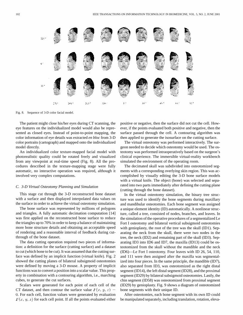
Fig. 8. Sequence of 3-D color facial model.
The patient might close his/her eyes during CT scanning, theeye features on the individualized model would also be repre-sented as closed eyes. Instead of point-to-point mapping, thecolor information of eye details was extracteden blocfrom 3-Dcolor portraits (cartograph) and mapped onto the individualizedmodel directly.
An individualized color texture-mapped facial model withphotorealistic quality could be rotated freely and visualizedfrom any viewpoint at real-time speed (Fig. 8). All the pro-cedures described in the texture-mapping stage were fullyautomatic, no interactive operation was required, although itinvolved very complex computations.
C. 3-D Virtual Osteotomy Planning and Simulation
This stage cut through the 3-D reconstructed bone datasetwith a surface and then displayed interpolated data values onthe surface in order to achieve the virtual osteotomy simulation.
The bone surface was represented by millions of polygonsand triangles. A fully automatic decimation computation [14]was first applied on the reconstructed bone surface to reducethe triangles up to 70% in order to keep a balance of maintainingmore bone structure details and obtaining an acceptable speedof rendering and a reasonable interval of feedback during cut-through of the bone dataset.
The data cutting operation required two pieces of informa-tion: a definition for the surface (cutting surface) and a datasetto cut (which bone to be cut). It was assumed that the cutting sur-face was defined by an implicit function (virtual knife). Fig. 2showed the cutting planes of bilateral subsigmoid osteotomieswere defined by moving a 3-D mouse. A property of implicitfunctions was to convert a position into a scalar value. This prop-erty in combination with a contouring algorithm, i.e., marchingcubes, to generate the cut surfaces.
Scalars were generated for each point of each cell of theCT dataset, and then contour the surface value. For each cell, function values were generated by evaluation
for each cell point. If all the points evaluated either
positive or negative, then the surface did not cut the cell. How-ever, if the points evaluated both positive and negative, then thesurface passed through the cell. A contouring algorithm wasthen applied to generate the isosurface on the cutting surface.
The virtual osteotomy was performed interactively. The sur-geon needed to decide which osteotomy would be used. The os-teotomy was performed intraoperatively based on the surgeon’sclinical experience. The immersible virtual-reality workbenchsimulated the environment of the operating room.
The decimated skull was subdivided into osteotomized seg-ments with a corresponding overlying skin region. This was ac-complished by visually editing the 3-D bone surface modelswith a virtual knife. The object (bone) was selected and sepa-rated into two parts immediately after defining the cutting plane(cutting through the bone dataset).
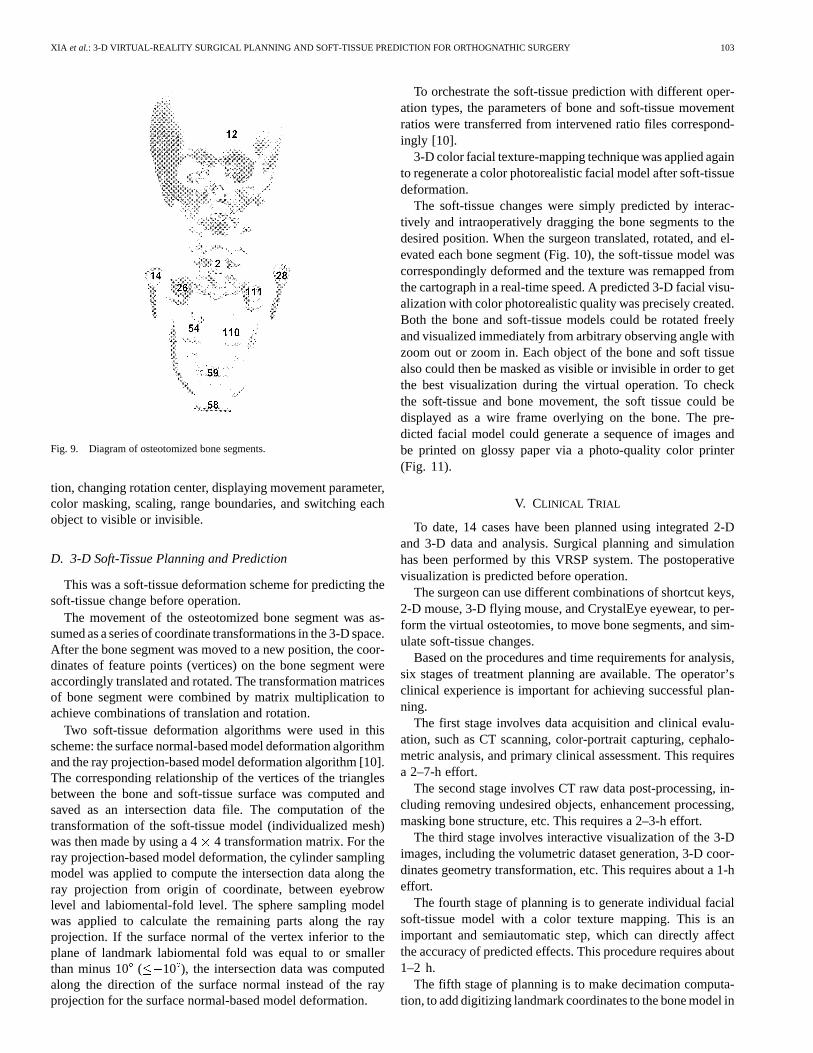
In the virtual osteotomy simulation, the binary tree struc-ture was used to identify the bone segments during maxillaryand mandibular osteotomies. Each bone segment was assigneda unique element identity (ID) automatically. A nonlinear struc-ture, called a tree, consisted of nodes, branches, and leaves. Inthe simulation of the operative procedures of a segmentalized LeFort I osteotomy and bilateral vertical subsigmoid osteotomieswith genioplasty, the root of the tree was the skull (ID1). Sep-arating the neck from the skull, there were two nodes in thetree, the neck (ID2) and remaining part of the skull (ID3). Sep-arating ID3 into ID6 and ID7, the maxilla (ID13) could be os-teotomized from the skull without the mandible and the neck(ID6)—Le Fort I osteotomy. Four leaves with ID 26, 54, 110,and 111 were then assigned after the maxilla was segmental-ized into four pieces. In the same principle, the mandible (ID7),also separated from ID3, was osteotomized as the right distalsegment (ID14), the left distal segment (ID28), and the proximalsegment (ID29) by bilateral subsigmoid osteotomies. Lastly, thechin segment (ID58) was osteotomized from proximal segment(ID29) by genioplasty. Fig. 9 shows a diagram of osteotomizedbone segments with their unique ID.
After osteotomies, each bone segment with its own ID couldbe manipulated separately, including translation, rotation, eleva-
XIA et al.: 3-D VIRTUAL-REALITY SURGICAL PLANNING AND SOFT-TISSUE PREDICTION FOR ORTHOGNATHIC SURGERY 103
Fig. 9. Diagram of osteotomized bone segments.
tion, changing rotation center, displaying movement parameter,color masking, scaling, range boundaries, and switching eachobject to visible or invisible.
D. 3-D Soft-Tissue Planning and Prediction
This was a soft-tissue deformation scheme for predicting thesoft-tissue change before operation.
The movement of the osteotomized bone segment was as-sumed as a series of coordinate transformations in the 3-D space.After the bone segment was moved to a new position, the coor-dinates of feature points (vertices) on the bone segment wereaccordingly translated and rotated. The transformation matricesof bone segment were combined by matrix multiplication toachieve combinations of translation and rotation.
Two soft-tissue deformation algorithms were used in thisscheme: the surface normal-based model deformation algorithmand the ray projection-based model deformation algorithm [10].The corresponding relationship of the vertices of the trianglesbetween the bone and soft-tissue surface was computed andsaved as an intersection data file. The computation of thetransformation of the soft-tissue model (individualized mesh)was then made by using a 44 transformation matrix. For theray projection-based model deformation, the cylinder samplingmodel was applied to compute the intersection data along theray projection from origin of coordinate, between eyebrowlevel and labiomental-fold level. The sphere sampling modelwas applied to calculate the remaining parts along the rayprojection. If the surface normal of the vertex inferior to theplane of landmark labiomental fold was equal to or smallerthan minus 10 ( 10 ), the intersection data was computedalong the direction of the surface normal instead of the rayprojection for the surface normal-based model deformation.
To orchestrate the soft-tissue prediction with different oper-ation types, the parameters of bone and soft-tissue movementratios were transferred from intervened ratio files correspond-ingly [10].
3-D color facial texture-mapping technique was applied againto regenerate a color photorealistic facial model after soft-tissuedeformation.
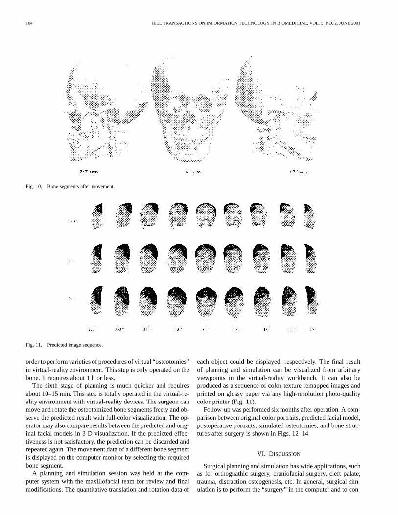
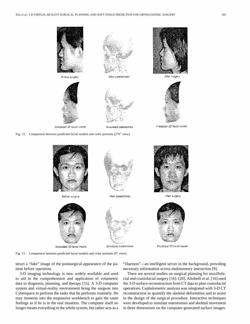
The soft-tissue changes were simply predicted by interac-tively and intraoperatively dragging the bone segments to thedesired position. When the surgeon translated, rotated, and el-evated each bone segment (Fig. 10), the soft-tissue model wascorrespondingly deformed and the texture was remapped fromthe cartograph in a real-time speed. A predicted 3-D facial visu-alization with color photorealistic quality was precisely created.Both the bone and soft-tissue models could be rotated freelyand visualized immediately from arbitrary observing angle withzoom out or zoom in. Each object of the bone and soft tissuealso could then be masked as visible or invisible in order to getthe best visualization during the virtual operation. To checkthe soft-tissue and bone movement, the soft tissue could bedisplayed as a wire frame overlying on the bone. The pre-dicted facial model could generate a sequence of images andbe printed on glossy paper via a photo-quality color printer(Fig. 11).
V. CLINICAL TRIAL
To date, 14 cases have been planned using integrated 2-Dand 3-D data and analysis. Surgical planning and simulationhas been performed by this VRSP system. The postoperativevisualization is predicted before operation.
The surgeon can use different combinations of shortcut keys,2-D mouse, 3-D flying mouse, and CrystalEye eyewear, to per-form the virtual osteotomies, to move bone segments, and sim-ulate soft-tissue changes.
Based on the procedures and time requirements for analysis,six stages of treatment planning are available. The operator’sclinical experience is important for achieving successful plan-ning.
The first stage involves data acquisition and clinical evalu-ation, such as CT scanning, color-portrait capturing, cephalo-metric analysis, and primary clinical assessment. This requiresa 2–7-h effort.
The second stage involves CT raw data post-processing, in-cluding removing undesired objects, enhancement processing,masking bone structure, etc. This requires a 2–3-h effort.
The third stage involves interactive visualization of the 3-Dimages, including the volumetric dataset generation, 3-D coor-dinates geometry transformation, etc. This requires about a 1-heffort.
The fourth stage of planning is to generate individual facialsoft-tissue model with a color texture mapping. This is animportant and semiautomatic step, which can directly affectthe accuracy of predicted effects. This procedure requires about1–2 h.
The fifth stage of planning is to make decimation computa-tion, to add digitizing landmark coordinates to the bone model in
104 IEEE TRANSACTIONS ON INFORMATION TECHNOLOGY IN BIOMEDICINE, VOL. 5, NO. 2, JUNE 2001
Fig. 10. Bone segments after movement.
Fig. 11. Predicted image sequence.
order to perform varieties of procedures of virtual “osteotomies”in virtual-reality environment. This step is only operated on thebone. It requires about 1 h or less.
The sixth stage of planning is much quicker and requiresabout 10–15 min. This step is totally operated in the virtual-re-ality environment with virtual-reality devices. The surgeon canmove and rotate the osteotomized bone segments freely and ob-serve the predicted result with full-color visualization. The op-erator may also compare results between the predicted and orig-inal facial models in 3-D visualization. If the predicted effec-tiveness is not satisfactory, the prediction can be discarded andrepeated again. The movement data of a different bone segmentis displayed on the computer monitor by selecting the requiredbone segment.
A planning and simulation session was held at the com-puter system with the maxillofacial team for review and finalmodifications. The quantitative translation and rotation data of
each object could be displayed, respectively. The final resultof planning and simulation can be visualized from arbitraryviewpoints in the virtual-reality workbench. It can also beproduced as a sequence of color-texture remapped images andprinted on glossy paper via any high-resolution photo-qualitycolor printer (Fig. 11).
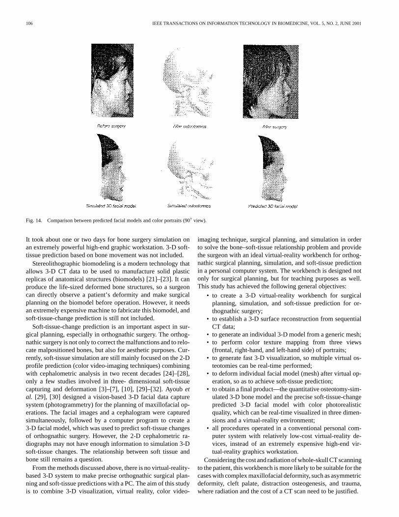
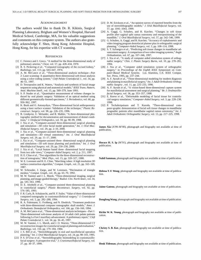
Follow-up was performed six months after operation. A com-parison between original color portraits, predicted facial model,postoperative portraits, simulated osteotomies, and bone struc-tures after surgery is shown in Figs. 12–14.
VI. DISCUSSION
Surgical planning and simulation has wide applications, suchas for orthognathic surgery, craniofacial surgery, cleft palate,trauma, distraction osteogenesis, etc. In general, surgical sim-ulation is to perform the “surgery” in the computer and to con-
XIA et al.: 3-D VIRTUAL-REALITY SURGICAL PLANNING AND SOFT-TISSUE PREDICTION FOR ORTHOGNATHIC SURGERY 105
Fig. 12. Comparison between predicted facial models and color portraits (270� view).
Fig. 13. Comparison between predicted facial models and color portraits (0� view).
struct a “fake” image of the postsurgical appearance of the pa-tient before operation.
3-D imaging technology is now widely available and usedto aid in the comprehension and application of volumetricdata to diagnosis, planning, and therapy [15]. A 3-D computersystem and virtual-reality environment bring the surgeon intoCyberspace to perform the tasks that he performs routinely. Hemay immerse into the responsive workbench to gain the samefeelings as if he is in the real situation. The computer itself nolonger means everything in the whole system, but rather acts as a
“Daemon”—an intelligent server in the background, providingnecessary information across multisensory interaction [9].
There are several studies on surgical planning for maxillofa-cial and craniofacial surgery [16]–[20]. Altobelliet al.[16] usedthe 3-D surface reconstruction from CT data to plan craniofacialoperations. Cephalometric analysis was integrated with 3-D CTreconstruction to quantify the skeletal deformities and to assistin the design of the surgical procedure. Interactive techniqueswere developed to simulate osteotomies and skeletal movementin three dimensions on the computer-generated surface images.
106 IEEE TRANSACTIONS ON INFORMATION TECHNOLOGY IN BIOMEDICINE, VOL. 5, NO. 2, JUNE 2001
Fig. 14. Comparison between predicted facial models and color portraits (90� view).
It took about one or two days for bone surgery simulation onan extremely powerful high-end graphic workstation. 3-D soft-tissue prediction based on bone movement was not included.
Stereolithographic biomodeling is a modern technology thatallows 3-D CT data to be used to manufacture solid plasticreplicas of anatomical structures (biomodels) [21]–[23]. It canproduce the life-sized deformed bone structures, so a surgeoncan directly observe a patient’s deformity and make surgicalplanning on the biomodel before operation. However, it needsan extremely expensive machine to fabricate this biomodel, andsoft-tissue-change prediction is still not included.
Soft-tissue-change prediction is an important aspect in sur-gical planning, especially in orthognathic surgery. The orthog-nathic surgery is not only to correct the malfunctions and to relo-cate malpositioned bones, but also for aesthetic purposes. Cur-rently, soft-tissue simulation are still mainly focused on the 2-Dprofile prediction (color video-imaging techniques) combiningwith cephalometric analysis in two recent decades [24]–[28],only a few studies involved in three- dimensional soft-tissuecapturing and deformation [3]–[7], [10], [29]–[32]. Ayoubetal. [29], [30] designed a vision-based 3-D facial data capturesystem (photogrammetry) for the planning of maxillofacial op-erations. The facial images and a cephalogram were capturedsimultaneously, followed by a computer program to create a3-D facial model, which was used to predict soft-tissue changesof orthognathic surgery. However, the 2-D cephalometric ra-diographs may not have enough information to simulation 3-Dsoft-tissue changes. The relationship between soft tissue andbone still remains a question.
From the methods discussed above, there is no virtual-reality-based 3-D system to make precise orthognathic surgical plan-ning and soft-tissue predictions with a PC. The aim of this studyis to combine 3-D visualization, virtual reality, color video-
imaging technique, surgical planning, and simulation in orderto solve the bone–soft-tissue relationship problem and providethe surgeon with an ideal virtual-reality workbench for orthog-nathic surgical planning, simulation, and soft-tissue predictionin a personal computer system. The workbench is designed notonly for surgical planning, but for teaching purposes as well.This study has achieved the following general objectives:
• to create a 3-D virtual-reality workbench for surgicalplanning, simulation, and soft-tissue prediction for or-thognathic surgery;
• to establish a 3-D surface reconstruction from sequentialCT data;
• to generate an individual 3-D model from a generic mesh;• to perform color texture mapping from three views
(frontal, right-hand, and left-hand side) of portraits;• to generate fast 3-D visualization, so multiple virtual os-
teotomies can be real-time performed;• to deform individual facial model (mesh) after virtual op-
eration, so as to achieve soft-tissue prediction;• to obtain a final product—the quantitative osteotomy-sim-
ulated 3-D bone model and the precise soft-tissue-changepredicted 3-D facial model with color photorealisticquality, which can be real-time visualized in three dimen-sions and a virtual-reality environment;
• all procedures operated in a conventional personal com-puter system with relatively low-cost virtual-reality de-vices, instead of an extremely expensive high-end vir-tual-reality graphics workstation.
Considering the costand radiation of whole-skullCTscanningto the patient, this workbench is more likely to be suitable for thecases with complex maxillofacial deformity, such as asymmetricdeformity, cleft palate, distraction osteogenesis, and trauma,where radiation and the cost of a CT scan need to be justified.
XIA et al.: 3-D VIRTUAL-REALITY SURGICAL PLANNING AND SOFT-TISSUE PREDICTION FOR ORTHOGNATHIC SURGERY 107
ACKNOWLEDGMENT
The authors would like to thank Dr. R. Kikinis, SurgicalPlanning Laboratory, Brigham and Women’s Hospital, HarvardMedical School, Cambridge, MA, for his valuable suggestionsand comments on this computer system. The authors also grate-fully acknowledge F. Shen, Hong Kong Adventist Hospital,Hong Kong, for his expertise with CT scanning.
REFERENCES
[1] C. Ferencz and J. Greco, “A method for the three-dimensional study ofpulmonary arteries,”Chest, vol. 57, pp. 428–434, 1970.
[2] R. S. Pickeringet al., “Computed tomography of the excised kidney,”Radiology, vol. 113, pp. 643–647, 1974.
[3] A. M. McCanceet al., “Three-dimensional analysis technique—Part2: Laser scanning: A quantitative three-dimensional soft-tissue analysisusing a color-coding system,”Cleft Palate Craniofacial J., vol. 34, pp.46–51, 1997.
[4] D. Terzopoulos and K. Waters, “Analysis and synthesis of facial imagesequences using physical and anatomical models,”IEEE Trans. Pattern,Anal. Machine Intell., vol. 15, pp. 569–579, June 1993.
[5] S. P. Studeret al., “Quantitative measurement of volume changes in-duced by oral plastic surgery: Validation of an optical method usingdifferent geometrically-formed specimens,”J. Periodontics, vol. 68, pp.950–962, 1997.
[6] K. Bush and O. Antonyshyn, “Three-dimensional facial anthropometryusing a laser surface scanner: Validation of the technique,”Plastic Re-construct. Surgery, vol. 98, pp. 226–235, 1996.
[7] B. Lindqvist, U. Welander, and R. Mahler, “A three-dimensional pho-tographic method for documentation and measurement of dental condi-tions,” J. Orofacial Orthopedics, vol. 59, pp. 90–99, 1998.
[8] J. Xia et al., “Computer-assisted three-dimensional surgical planningand simulation—3D color facial model generation,”Int. J. Oral Max-illofacial Surgery, vol. 29, pp. 2–10, 2000.
[9] J. Xia et al., “Computer-assisted three-dimensional surgical planningand simulation—3D virtual osteotomy,”Int. J. Oral MaxillofacialSurgery, vol. 29, pp. 11–17, 2000.
[10] J. Xia et al., “Computer-assisted three- dimensional surgical planningand simulation—3D soft tissue planning and prediction,”Int. J. OralMaxillofacical Surgery, vol. 29, pp. 250–258, 2000.
[11] J. Xia et al., “Local feature based three- dimensional facial mappingfrom two side views,”Computer-Aided Surgery, vol. 2, p. 211, 1997.
[12] H. E. Clineet al., “Two algorithms for the three-dimensional reconstruc-tion of tomograms,”Med. Phys., vol. 15, pp. 320–327, 1988.
[13] W. E. Lorensen and H. E. Cline, “Marching cubes: A high resolution 3Dsurface construction algorithm,”Comput. Graph., vol. 21, pp. 163–169,1987.
[14] W. Schroeder, J. Zarge, and W. Lorensen, “Decimation of trianglemeshes,”Comput. Graph., vol. 26, pp. 65–70, 1992.
[15] M. W. Vannier and J. L. Marsh, “Three-dimensional imaging, surgicalplanning, and image-guided therapy,”Radiol. Clin. North Amer., vol. 34,pp. 545–563, 1996.
[16] D. E. Altobelli et al., “Computer-assisted three-dimensional planningin craniofacial surgery,”Plastic Reconstruct. Surgery, vol. 92, pp.576–585, 1993.
[17] F. R. Carls, B. Schuknecht, and H. F. Sailer, “Value of three-dimensionalcomputed tomography in craniomaxillofacial surgery,”J. CraniofacialSurgery, vol. 5, pp. 282–288, 1994.
[18] R. A. Fuhrmann, U. Frohberg, and N. Diedrich, “Treatment predictionwith three-dimensional computer tomographic skull models,”Amer. J.Orthodontic Dentofacial Orthopedics, vol. 106, pp. 156–160, 1994.
[19] A. M. McCanceet al., “Three-dimensional analysis techniques—Part 1:Three-dimensional soft-tissue analysis of 24 adult cleft palate patientsfollowing Le Fort I maxillary advancement: A preliminary report,”CleftPalate Craniofacial J., vol. 34, pp. 36–45, 1997.
[20] M. W. Vannier, J. L. Marsh, and J. O. Warren, “Three-dimensional CTreconstruction images for craniofacial surgical planning and evaluation,”Radiology, vol. 150, pp. 179–184, 1984.
[21] J. S. Bill et al., “Stereolithography in oral and maxillofacial operationplanning,”Int. J. Oral Maxillofacial Surgery, vol. 24, pp. 98–103, 1995.
[22] P. S. D’Ursoet al., “Stereolithographic biomodeling in craniomaxillo-facial surgery: A prospective trial,”J. Craniomaxillofacial Surgery, vol.27, pp. 30–37, 1999.
[23] D. M. Ericksonet al., “An opinion survey of reported benefits from theuse of stereolithographic models,”J. Oral Maxillofacial Surgery, vol.57, pp. 1041–1043, 1999.
[24] A. Gaggl, G. Schultes, and H. Karcher, “Changes in soft tissueprofile after sagittal split ramus osteotomy and retropositioning of themandible,”J. Oral Maxillofacial Surgery, vol. 57, pp. 542–546, 1999.
[25] G. Schultes, A. Gaggl, and H. Karcher, “Accuracy of cephalometric andvideo imaging program dentofacial planner plus in orthognathic surgicalplanning,”Computer-Aided Surgery, vol. 3, pp. 108–114, 1998.
[26] S. T. Syliangcoet al., “Predicting soft tissue changes in mandibular ad-vancement surgery: A comparison of two video imaging systems,”AngleOrthodontists, vol. 67, pp. 337–346, 1997.
[27] J. Xia et al., “A study of computer aided simulation system of orthog-nathic surgery,”Chin. J. Plastic Surgery Burns, vol. 10, pp. 278–281,1994.
[28] J. Xia et al., “Computer aided simulation system of orthognathicsurgery,” in Proceedings of the Eighth IEEE Symposium on Com-puter-Based Medical Systems. Los Alamitos, CA: IEEE Comput.Soc. Press, 1995, pp. 237–244.
[29] A. F. Ayoubet al., “Three-dimensional modeling for modern diagnosisand planning in maxillofacial surgery,”Int. J. Adult Orthodontic Orthog-nathic Surgery, vol. 11, pp. 225–233, 1996.
[30] A. F. Ayoub et al., “A vision-based three-dimensional capture systemfor maxillofacial assessment and surgical planning,”Br. J. Oralmaxillo-facial Surgery, vol. 36, pp. 353–357, 1998.
[31] E. Keeveet al., “Deformable modeling of facial tissue for craniofa-cial surgery simulation,”Computer-Aided Surgery, vol. 3, pp. 228–238,1998.
[32] P. Techalertpaisarn and T. Kuroda, “Three-dimensional com-puter-graphic demonstration of facial soft tissue changes in mandibularprognathic patients after mandibular sagittal ramus osteotomy,”Int. J.Adult Orthodontic Orthognathic Surgery, vol. 13, pp. 217–225, 1998.
James Xia (A’99–M’00), photograph and biography not available at time ofpublication.
Horace H. S. Ip (M’91), photograph and biography not available at time ofpublication.
Nabil Samman, photograph and biography not available at time of publication.
Helena T. F. Wong, photograph and biography not available at time of publica-tion.
Jaime Gateno, photograph and biography not available at time of publication.
Dongfeng Wang, photograph and biography not available at time of publication.
Richie W. K. Yeung, photograph and biography not available at time of publi-cation.
Christy S. B. Kot, photograph and biography not available at time of publica-tion.
Henk Tideman, photograph and biography not available at time of publication.