Embed Size (px)
Citation preview
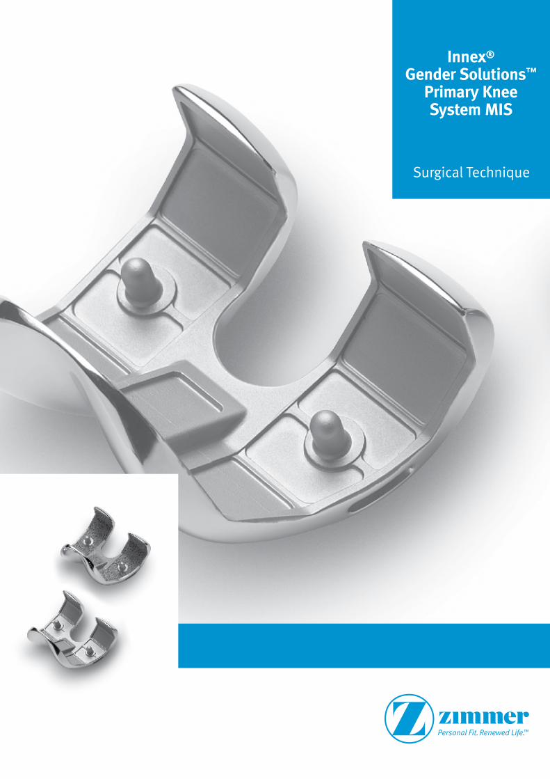
Innex® Gender Solutions™
Primary Knee System MIS
Surgical Technique

2 Innex® Gender Solutions™ Primary Knee System MIS
3Innex® Gender Solutions™ Primary Knee System MIS
Contents
Prostheses with Mobile Bearings 4
Prostheses with Fixed Bearings 5
Minimally Invasive Total Knee Replacement 6
Introduction MIS 6
Indication
Contraindication 7
Preoperative Planning 8
Preoperative Planning with X-Ray Templates 10
Tourniquet 11
Patient Positioning 11
Subvastus Approach 12
Midvastus Approach 12
Mini Medial Arthrotomy 13
Preparation of the Soft Tissues 14
Overview of the Cutting Steps 15
Surgical Instructions 16
Preparation of the Tibia 16
Preparation of the Femur 22
Preparation of the Anchoring Stem (optional) 37
Positioning the Trial Components 38
Preparation of the Patella (optional) 40
Assembly of the Anchoring Stem (optional) 42
Implantation 45
Combination Table of the Mobile Bearing System 48
Combination Table of the Fixed Bearing System 49
4 Innex® Gender Solutions™ Primary Knee System MIS
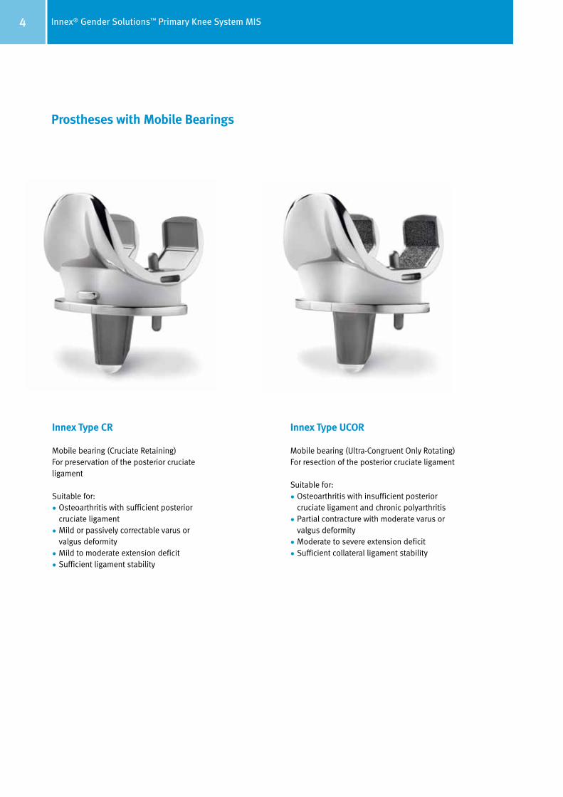
Prostheses with Mobile Bearings
Innex Type CR
Mobile bearing (Cruciate Retaining)For preservation of the posterior cruciate ligament
Suitable for:
• Osteoarthritis with sufficient posterior cruciate ligament
• Mild or passively correctable varus or valgus deformity
• Mild to moderate extension deficit
• Sufficient ligament stability
Innex Type UCOR
Mobile bearing (Ultra-Congruent Only Rotating) For resection of the posterior cruciate ligament
Suitable for:
• Osteoarthritis with insufficient posterior cruciate ligament and chronic polyarthritis
• Partial contracture with moderate varus or valgus deformity
• Moderate to severe extension deficit
• Sufficient collateral ligament stability
5Innex® Gender Solutions™ Primary Knee System MIS
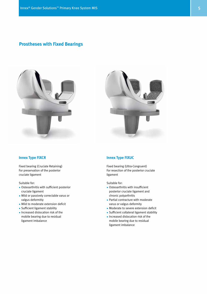
Prostheses with Fixed Bearings
Innex Type FIXCR
Fixed bearing (Cruciate Retaining)For preservation of the posterior cruciate ligament
Suitable for:
• Osteoarthritis with sufficient posterior cruciate ligament
• Mild or passively correctable varus or valgus deformitiy
• Mild to moderate extension deficit
• Sufficient ligament stability
• Increased dislocation risk of the mobile bearing due to residual ligament imbalance
Innex Type FIXUC
Fixed bearing (Ultra-Congruent)For resection of the posterior cruciate ligament
Suitable for:
• Osteoarthritis with insufficient posterior cruciate ligament and chronic polyarthritis
• Partial contracture with moderate varus or valgus deformity
• Moderate to severe extension deficit
• Sufficient collateral ligament stability
• Increased dislocation risk of the mobile bearing due to residual ligament imbalance
6 Innex® Gender Solutions™ Primary Knee System MIS
Minimally Invasive Total Knee Replacement
Introduction MIS
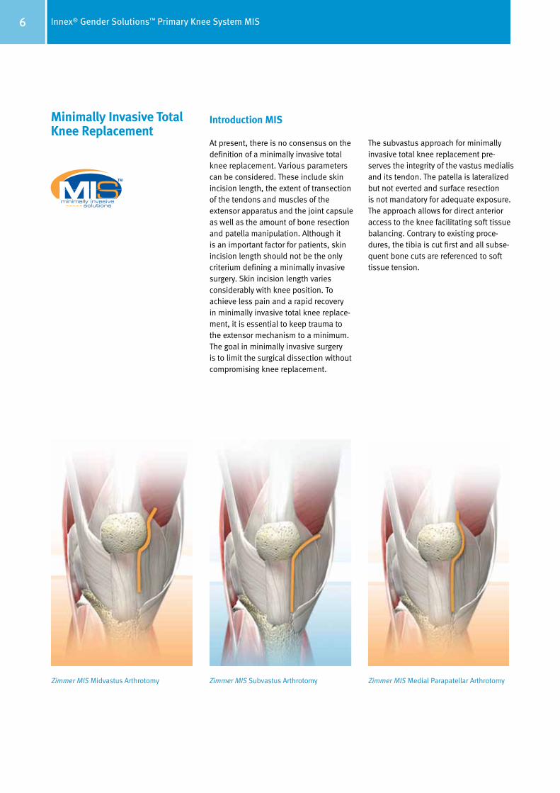
At present, there is no consensus on the definition of a minimally invasive total knee replacement. Various parameters can be considered. These include skin incision length, the extent of transection of the tendons and muscles of the extensor apparatus and the joint capsule as well as the amount of bone resection and patella manipulation. Although it is an important factor for patients, skin incision length should not be the only criterium defining a minimally invasive surgery. Skin incision length varies considerably with knee position. To achieve less pain and a rapid recovery in minimally invasive total knee replace-ment, it is essential to keep trauma to the extensor mechanism to a minimum. The goal in minimally invasive surgery is to limit the surgical dissection without compromising knee replacement.
The subvastus approach for minimally invasive total knee replacement pre-serves the integrity of the vastus medialis and its tendon. The patella is lateralized but not everted and surface resection is not mandatory for adequate exposure. The approach allows for direct anterior access to the knee facilitating soft tissue balancing. Contrary to existing proce-dures, the tibia is cut first and all sub se-quent bone cuts are referenced to soft tissue tension.
Zimmer MIS Midvastus Arthrotomy Zimmer MIS Subvastus Arthrotomy Zimmer MIS Medial Parapatellar Arthrotomy
7Innex® Gender Solutions™ Primary Knee System MIS
Indication
Patients for minimally invasive total knee replacement should be carefully selected. The indication for the minimally invasive procedure should be restrictive to avoid encountering intraoperative problems and jeopardizing patient care.
Mild to moderate varus knees with less than 10° varus angle are a favorable in di cation since the medial joint capsule is easily accessed. The indication is limited to mild and passively correctable valgus knees with less than 15° valgus angle because access to the lateral side is more difficult, making lateral ligament releases hard to carry out. It must be possible to flex to about 90° in order to lateralize the patella.
Finally, a narrow femur is easier to handle as soft tissue traction is mainly on the lateral side.
Contraindication
Severe varus deformities need releases beyond the extent of minimal incisions. A flexion contracture should not exceed 15° as extensive posterior releases are difficult to perform through minimal incisions.
A high body mass index makes a patient less suitable for minimally invasive total knee replacement as a thick subcu-taneous tissue layer decreases visibility. On the other hand, an extremely thin subcutaneous tissue layer is difficult to retract and tends to develop wound healing problems.
8 Innex® Gender Solutions™ Primary Knee System MIS
Preoperative Planning The preoperative planning comprises the indication, evaluation and preparation important for the success of the surgery. Preoperative planning also includes patient education, preoperative medical examinations, assessing the risk of the surgery and choice of anesthesia.
Preoperative X-rays are essential for surgical planning. We recommend a
single-leg stance X-ray in the anterior/ posterior (A/P) plane and a long-leg X-ray with weight on both legs. In addition, it may be useful to have a lateral X-ray of the knee joint in 90° flexion or in extension as well as a skyline view of the patella in 40° flexion.
Long-leg X-rays help to detect deviations of the axis and deformities in the dia-physeal area of the femur and the tibia. Long-leg X-rays help also to determine whether an intramedullary or an extramedullary alignment can be used.
Furthermore, the mechanical and anatomical axes of the leg can be plotted and the femoral angle a, representing the difference between the two, can be determined (see page 10). This angle is usually about 6° but varies depending
on morphology and femur size. The distal femoral cut is determined by the femoral angle bushing. The bushing is chosen according to the femoral angle a (see pages 24 and 26). Three femoral angle bushings are available with 4°, 6° and 8° valgus angle.
The entry point for the intramedullary alignment guide is determined by extending the line of the anatomical axis of the femur. Usually, the entry point is slightly medial to the center of the femoral condyles.
The extent of tibial resection can be determined on the long-leg X-ray. In this way, the magnitude of the medial and lateral bone resection can be evaluated (see page 10). This is especially impor-tant for extensive bone defects in order to avoid a too radical resection. It is pre-ferable to treat defects in primary knee arthroplasty with autologous bone grafts.
9Innex® Gender Solutions™ Primary Knee System MIS
α
C A
E
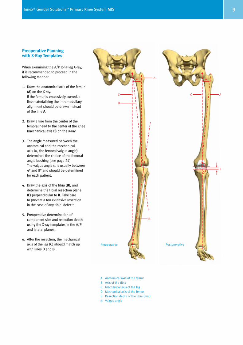
Preoperative Planning with X-Ray Templates
When examining the A/P long-leg X-ray, it is recommended to proceed in the following manner:
1. Draw the anatomical axis of the femur (A) on the X-ray. If the femur is excessively curved, a line materializing the intramedullary alignment should be drawn instead of the line A.
2. Draw a line from the center of the femoral head to the center of the knee (mechanical axis D) on the X-ray.
3. The angle measured between the anatomical and the mechanical axis (α, the femoral valgus angle) determines the choice of the femoral angle bushing (see page 24).
The valgus angle α is usually between 4° and 8° and should be determined for each patient.
4. Draw the axis of the tibia (B), and determine the tibial resection plane (E) perpendicular to B. Take care to prevent a too extensive resection in the case of any tibial defects.
5. Preoperative determination of component size and resection depth using the X-ray templates in the A/P and lateral planes.
6. After the resection, the mechanical axis of the leg (C) should match up with lines D and B.
A Anatomical axis of the femurB Axis of the tibiaC Mechanical axis of the legD Mechanical axis of the femurE Resection depth of the tibia (mm)α Valgus angle
Preoperative Postoperative
C
D
Aα
B
10 Innex® Gender Solutions™ Primary Knee System MIS
Subvastus Approach Begin with a midline skin incision starting from the proximal pole of the patella down to the tibial tubercle (page 6). While the proximal part of the skin incision is needed to insert the femoral component, the distal part is needed for the tibial cut. Cut down the sub cu ta ne ous tissue to the level of the fascia in line with the skin incision. Then bluntly separate it from the fascia on top of the vastus medialis muscle and the medial retinaculum. Continue the dissection un derneath the skin in the proximal direction on the medial side on top of the vastus medialis. Incise the medial retinaculum just medially of the patella and the patellar tendon. Elevate the subcutaneous tissue and skin with two Langenbeck retractors and continue with sharp dissection proximally along the inferior border of the vastus me dialis muscle and down medially to the intermuscular septum. Then continue blunt dissection with a swab to lift the vastus medialis from the septum as far proximally as possible. Perform this up to the adductor hiatus. Be cautious not to harm the femoral artery and vein. Finally incise the joint capsule under neath the vastus medialis muscle in the proximal direction up to the superior pouch.
In the joint, resect the anterior part of the medial meniscus, the anterior cruciate ligament, the anterior part of the lateral meniscus and the inferior part of the Hoffa fat pad. Partial resection of the Hoffa fat pad prevents painful postoperative impingement.
Midvastus Approach1 Make a medial parapatellar incision into the capsule, preserving approximately 1 cm of peritenon and capsule medial to the patellar tendon (page 6). This step is important to facilitate complete closure of the capsule. Split the superficial enveloping fascia of the quadriceps muscle percutaneously in a proximal direction over a length of approximately 6cm. This mobilizes the quadriceps and allows for significantly greater lateral translation of the muscle while minimizing tension on the patellar tendon insertion.
Split the vastus medialis obliquis approximately 1.5cm–2cm.
Use blunt dissection to undermine the skin incision approximately 1cm–2cm around the patella. Flex the knee slightly and remove a third of the fat pad from the posterior side.
The patella can either be everted or subluxed. If everting the patella, release the lateral patellofemoral ligament to facilitate full eversion and lateral trans-lation of the patella. Then use hand-held three-pronged or two-pronged hooks and gently evert the patella. Be careful not to disrupt the extensor in sertion. To help evert the patella, flex the joint slowly and rotate the tibia externally while applying gentle pres-sure. Once the patella is everted, use a standard-size Homann retractor or two small Homann retractors along the lateral flare of the tibial metaphysis to maintain the eversion of the patella and the extensor mechanism.
Remove any large patellar osteophytes.
Release the anterior cruciate ligament (if present). Dissect subperiosteally along the proximal medial and lateral tibia to the level of the tibial tendon insertion. Then release the lateral cap-sule (less than 5mm) to help minimize tension on the extensor mechanism.
Note
It is imperative to maintain a minimal tension of the patellar tendon throughout the procedure. This is especially im portant during eversion of the patella and positioning of the pa tient. In addition, make sure that the split in the vastus medialis obliquis never extends more than 4.5cm proxi mally during retraction. Neurovascular damage to the medial aspect of the qua driceps could occur as a conse quence.2
11Innex® Gender Solutions™ Primary Knee System MIS
Mini Medial Arthrotomy3 Minimally invasive total knee arthroplasty can be performed with a limited medial parapatellar arthrotomy. Make a 10cm– 14cm midline skin incision from the proximal aspect of the tibial tubercle to the proximal border of the patella. After dissecting subcutaneously, make medial and lateral flaps, and dissect proximally and distally to expose the extensor mechanism. This allows mobilization of the skin and subcutaneous tissue during the procedure. Due to the elasticity of the skin the incision will stretch 2cm – 4cm additionally allowing broader exposure of the knee joint with the knee in flexion.
The goal in minimally invasive surgery is to limit the surgical dissection without compromising knee replacement. The medial parapatellar arthrotomy is used to expose the joint. However, the length of the proximal division of the quadriceps tendon only allows for lateral subluxation of the patella and not eversion. Start with a 2cm – 4cm incision of the quadriceps tendon. If it is difficult to displace the patella laterally or if the patellar tendon is at risk of tearing extend the arthrotomy proximally along the quadriceps tendon until adequate exposure is achieved.
Subluxate the patella laterally and place retractors to protect the supporting soft tissue structures. The incision can be moved as a “mobile window” from me dial to lateral and from proximal to distal as necessary to enhance visibility without applying undue force to the skin and subcutaneous tissues.
For more information, please refer to the:
1 Natural-Knee II MIS Surgical Technique Midvastus Approach
2 Cooper RE, Trinidad G, Buck, WR. Midvastus Approach in Total Knee Arhtroplasty. J Arthroplasty 1999: 14 (4): 505–508
3 Natural-Knee II MIS Surgical Technique Mini Medial Arthrotomy

12 Innex® Gender Solutions™ Primary Knee System MIS
Assessment of the posterior slope of the tibial plateau is made with a lateral X-ray. In general this slope ranges between 3° and 10°.
The status of the patella alta/baja is determined from the lateral X-ray. Any tilt/subluxation of the patella can be seen in the skyline view. This information can influence additional intraoperative decisions regarding the extensor mechanism.
It is not recommended to resurface the patella as a routine. In fact, resurfacing is doubtful in the case of a alta/baja patella position.
Where patella replacement is indicated, there are four sizes of cemented patella implants available.
13Innex® Gender Solutions™ Primary Knee System MIS
Tourniquet
The surgery is carried out on patients under general or spinal anesthesia. Postoperative pain is significantly re duced without the use of a tourniquet. Furthermore a tourniquet clamps the quadriceps muscle and interferes with its tension. Optimal muscle relaxation is necessary for minimally invasive surgery. In addition, it is safer to control bleeding throughout the procedure than only at the end of the surgery. If neces sary to apply a tourniquet, it should be placed as high as possible and be inflated at maximum 100 mm Hg above systolic blood pressure.
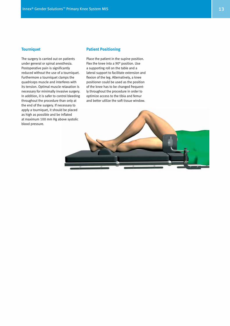
Patient Positioning Place the patient in the supine position. Flex the knee into a 90° position. Use a supporting roll on the table and a lateral support to facilitate extension and flexion of the leg. Alternatively, a knee positioner could be used as the position of the knee has to be changed frequent-ly throughout the procedure in order to optimize access to the tibia and femur and better utilize the soft tissue window.
14 Innex® Gender Solutions™ Primary Knee System MIS
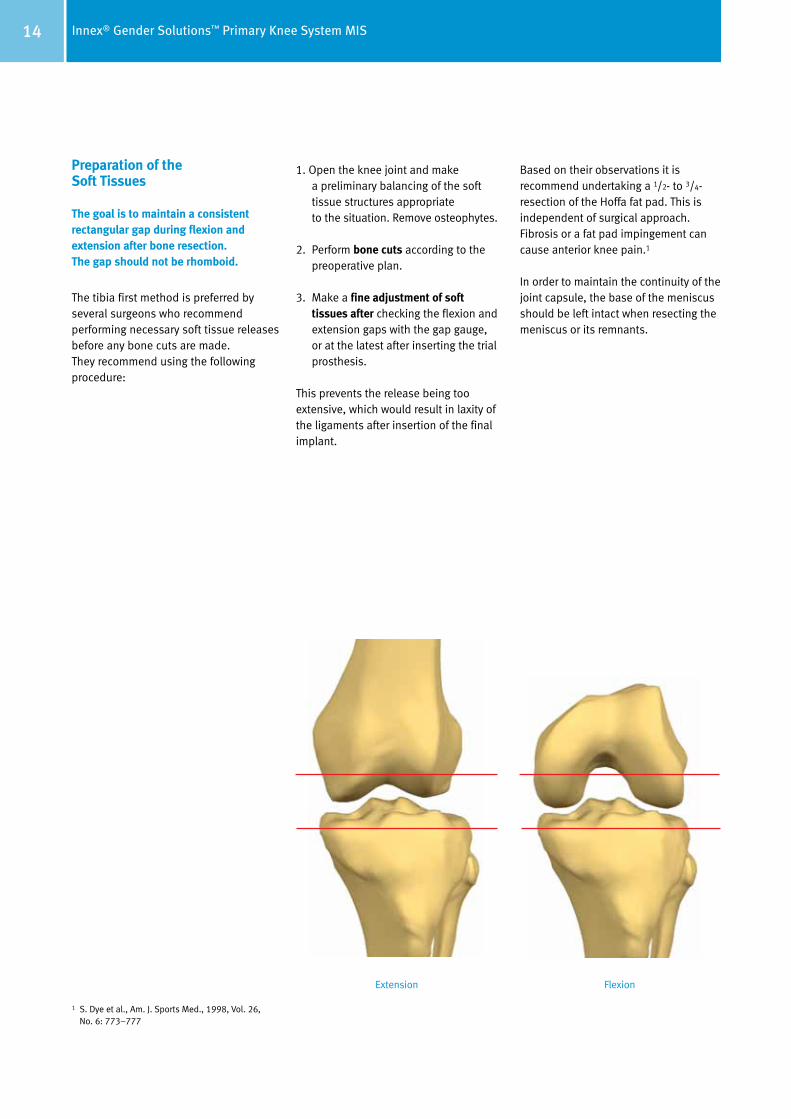
Preparation of the Soft Tissues The goal is to maintain a consistent rectangular gap during flexion and extension after bone resection. The gap should not be rhomboid.
The tibia first method is preferred by several surgeons who recommend performing necessary soft tissue releases before any bone cuts are made. They recommend using the following procedure:
1. Open the knee joint and make a preliminary balancing of the soft tissue structures appropriate to the situation. Remove osteophytes.
2. Perform bone cuts according to the preoperative plan.
3. Make a fine adjustment of soft tissues after checking the flexion and extension gaps with the gap gauge, or at the latest after inserting the trial prosthesis.
This prevents the release being too extensive, which would result in laxity of the ligaments after insertion of the final implant.
Based on their observations it is recommend undertaking a 1/2- to 3/4-resection of the Hoffa fat pad. This is independent of surgical approach. Fibrosis or a fat pad impingement can cause anterior knee pain.1
In order to maintain the continuity of the joint capsule, the base of the meniscus should be left intact when resecting the meniscus or its remnants.
Extension Flexion
1 S. Dye et al., Am. J. Sports Med., 1998, Vol. 26, No. 6: 773–777
15Innex® Gender Solutions™ Primary Knee System MIS
It is important to define the flexion gap first and then to adjust the extension gap to the flexion gap, and not vice versa. The correct ligament balance of the prosthesis can only be achieved if the flexion and extension gaps are identical.
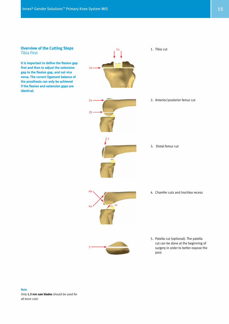
Overview of the Cutting Steps Tibia First
1. Tibia cut
2. Anterior/posterior femur cut
3. Distal femur cut
4. Chamfer cuts and trochlea recess
5. Patella cut (optional). The patella cut can be done at the beginning of surgery in order to better expose the joint
Note
Only 1.3 mm saw blades should be used for
all bone cuts!
1a
1b
2a
2b
3
4b
4a 4c
5
16 Innex® Gender Solutions™ Primary Knee System MIS
D
E
G
C
F
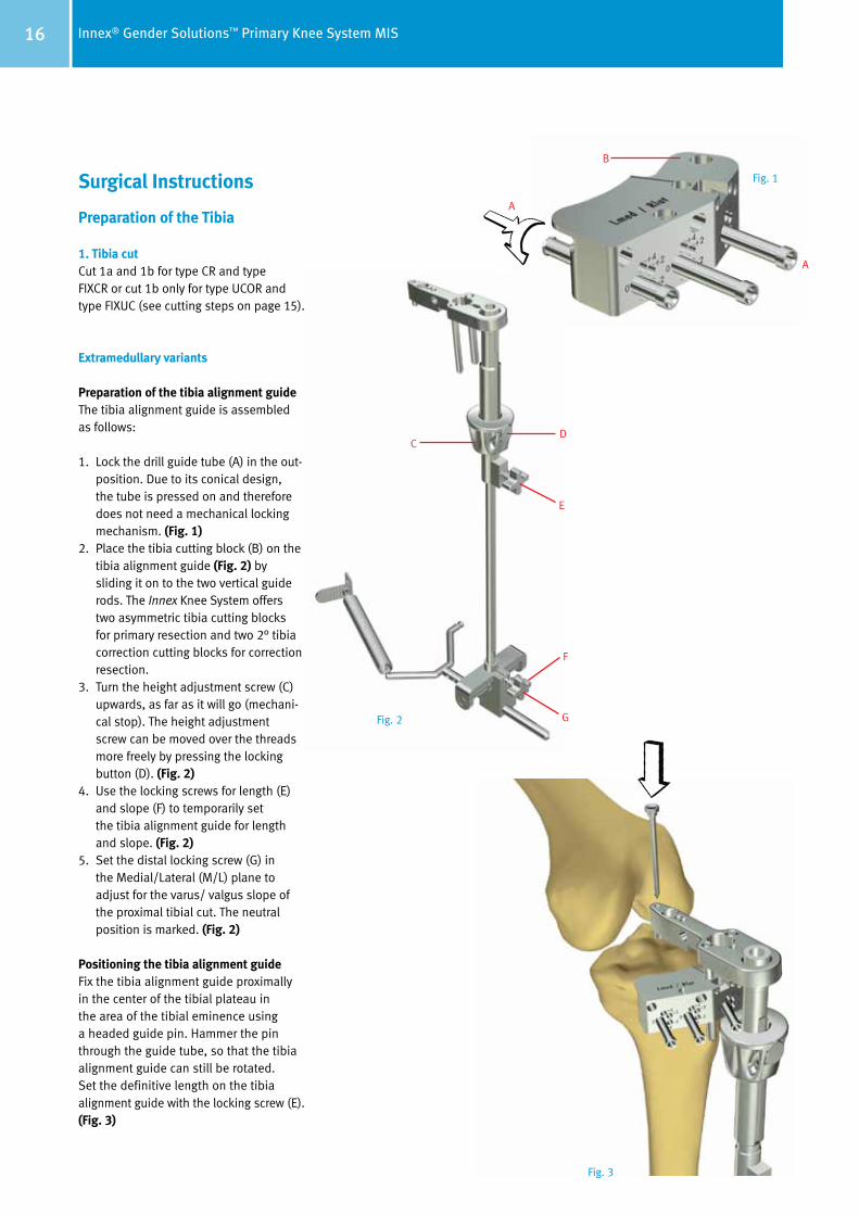
Surgical Instructions Preparation of the Tibia
1. Tibia cutCut 1a and 1b for type CR and type FIXCR or cut 1b only for type UCOR and type FIXUC (see cutting steps on page 15).
Extramedullary variants
Preparation of the tibia alignment guideThe tibia alignment guide is assembled as follows:
1. Lock the drill guide tube (A) in the out- position. Due to its conical design, the tube is pressed on and therefore does not need a mechanical locking mechanism. (Fig. 1)
2. Place the tibia cutting block (B) on the tibia alignment guide (Fig. 2) by sliding it on to the two vertical guide rods. The Innex Knee System offers two asymmetric tibia cutting blocks for primary resection and two 2° tibia correction cutting blocks for correction resection.
3. Turn the height adjustment screw (C) upwards, as far as it will go (mechani-cal stop). The height adjustment screw can be moved over the threads more freely by pressing the locking button (D). (Fig. 2)
4. Use the locking screws for length (E) and slope (F) to temporarily set the tibia alignment guide for length and slope. (Fig. 2)
5. Set the distal locking screw (G) in the Medial/Lateral (M/L) plane to adjust for the varus/ valgus slope of the proximal tibial cut. The neutral position is marked. (Fig. 2)
Positioning the tibia alignment guideFix the tibia alignment guide proximally in the center of the tibial plateau in the area of the tibial eminence using a headed guide pin. Hammer the pin through the guide tube, so that the tibia alignment guide can still be rotated. Set the definitive length on the tibia alignment guide with the locking screw (E). (Fig. 3)
B
A
A
Fig. 1
Fig. 2
Fig. 3
17Innex® Gender Solutions™ Primary Knee System MIS
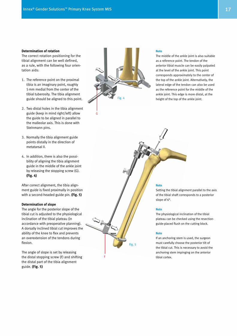
Determination of rotationThe correct rotation positioning for the tibial alignment can be well defined, as a rule, with the following four orien-tation aids:
1. The reference point on the proximal tibia is an imaginary point, roughly 5 mm medial from the center of the tibial tuberosity. The tibia alignment guide should be aligned to this point.
2. Two distal holes in the tibia alignment guide (keep in mind right/left) allow the guide to be aligned in parallel to the malleolar axis. This is done with Steinmann pins.
3. Normally the tibia alignment guide points distally in the direction of metatarsal II.
4. In addition, there is also the possi-bility of aligning the tibia alignment guide in the middle of the ankle joint by releasing the stopping screw (G). (Fig. 4)
After correct alignment, the tibia align-ment guide is fixed proximally in position with a second-headed guide pin. (Fig. 5)
Determination of slopeThe angle for the posterior slope of the tibial cut is adjusted to the physiological inclination of the tibial plateau (in accordance with preoperative planning). A dorsally inclined tibial cut improves the ability of the knee to flex and prevents an overextension of the tendons during flexion.
The angle of slope is set by releasing the distal stopping screw (F) and shifting the distal part of the tibia alignment guide. (Fig. 5)
Note
The middle of the ankle joint is also suitable
as a reference point. The tendon of the
anterior tibial muscle can be easily palpated
at the level of the ankle joint. This point
corresponds approximately to the center of
the top of the ankle joint. Alternatively, the
lateral edge of the tendon can also be used
as the reference point for the middle of the
ankle joint. This edge is more distal, at the
height of the top of the ankle joint.
Note
Setting the tibial alignment parallel to the axis
of the tibial shaft corresponds to a posterior
slope of 6°.
Note
The physiological inclination of the tibial
plateau can be checked using the resection-
guide-placed flush on the cutting block.
Note
If an anchoring stem is used, the surgeon
must carefully choose the posterior tilt of
the tibial cut. This is necessary to avoid the
anchoring stem impinging on the anterior
tibial cortex.
G
F
Fig. 4
Fig. 5
18 Innex® Gender Solutions™ Primary Knee System MIS
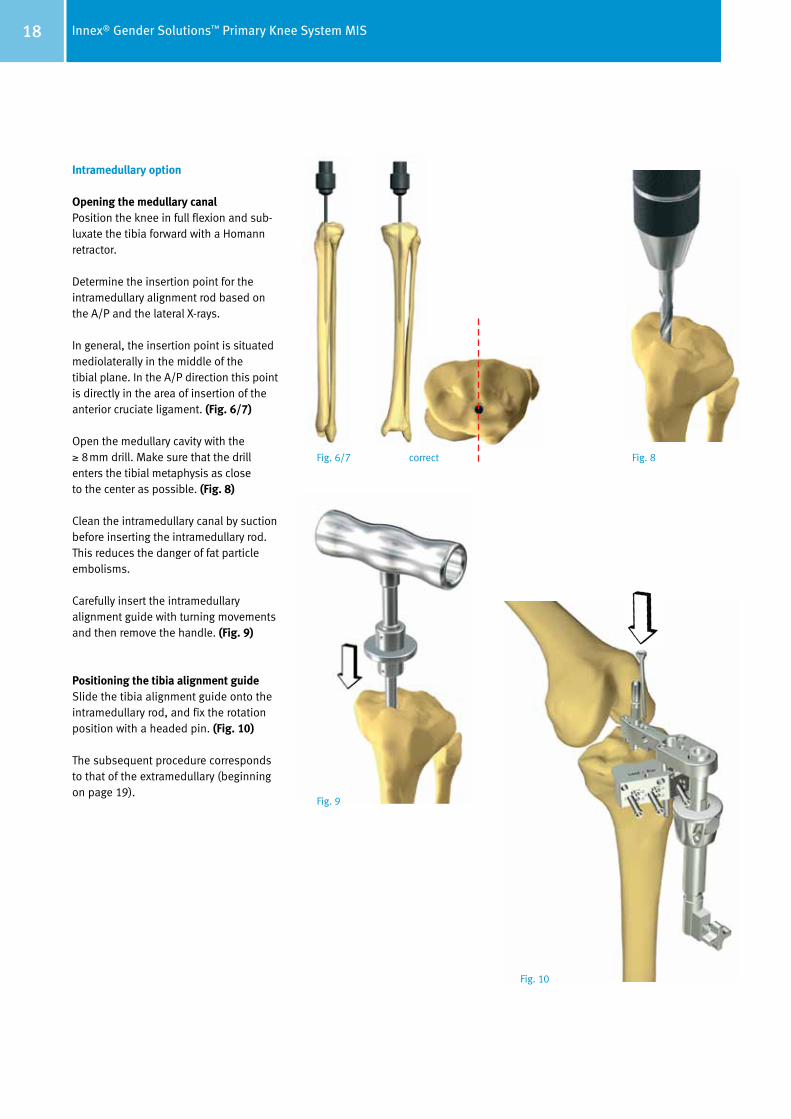
Intramedullary option
Opening the medullary canalPosition the knee in full flexion and sub-luxate the tibia forward with a Homann retractor.
Determine the insertion point for the intramedullary alignment rod based on the A/P and the lateral X-rays.
In general, the insertion point is situated mediolaterally in the middle of the tibial plane. In the A/P direction this point is directly in the area of insertion of the anterior cruciate ligament. (Fig. 6/7)
Open the medullary cavity with the ≥ 8mm drill. Make sure that the drill enters the tibial metaphysis as close to the center as possible. (Fig. 8)
Clean the intramedullary canal by suction before inserting the intramedullary rod. This reduces the danger of fat particle embolisms.
Carefully insert the intramedullary alignment guide with turning movements and then remove the handle. (Fig. 9)
Positioning the tibia alignment guideSlide the tibia alignment guide onto the intramedullary rod, and fix the rotation position with a headed pin. (Fig. 10)
The subsequent procedure corresponds to that of the extramedullary (beginning on page 19).
correctFig. 6/7 Fig. 8
Fig. 9
Fig. 10
19Innex® Gender Solutions™ Primary Knee System MIS
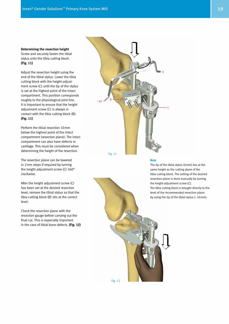
Determining the resection heightScrew and securely fasten the tibial stylus onto the tibia cutting block. (Fig. 11)
Adjust the resection height using the end of the tibial stylus. Lower the tibia cutting block with the height-adjust- ment screw (C) until the tip of the stylus is set at the highest point of the intact compart ment. This position corresponds roughly to the physiological joint line. It is im portant to ensure that the height adjust ment screw (C) is always in contact with the tibia cutting block (B). (Fig. 11)
Perform the tibial resection 10mm below the highest point of the intact compart ment (resection plane). The intact compartment can also have defects in cartilage. This must be considered when determining the height of the resection.
The resection plane can be lowered in 2mm steps if required by turning the height adjustment screw (C) 360° clockwise.
After the height adjustment screw (C) has been set at the desired resection level, remove the tibial stylus so that the tibia cutting block (B) sits at the correct level.
Check the resection plane with the resection gauge before carrying out the final cut. This is especially important in the case of tibial bone defects. (Fig. 12)
B
C
0
–10
Note
The tip of the tibial stylus (0mm) lies at the
same height as the cutting plane of the
tibia cutting block. The setting of the desired
resection plane is done manually by turning
the height-adjustment screw (C).
The tibia cutting block is brought directly to the
level of the recommended resection plane
by using the tip of the tibial stylus (–10mm).
Fig. 11
Fig. 12
20 Innex® Gender Solutions™ Primary Knee System MIS
C
E
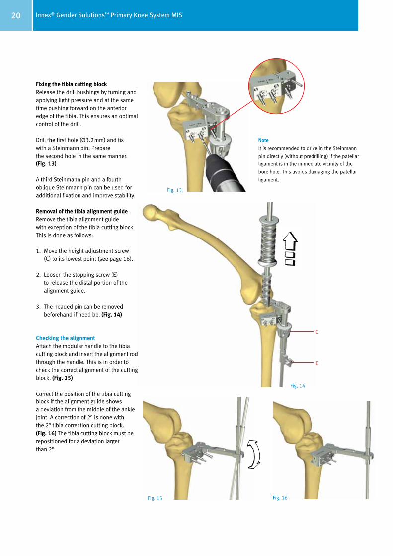
Fixing the tibia cutting blockRelease the drill bushings by turning and applying light pressure and at the same time pushing forward on the anterior edge of the tibia. This ensures an optimal control of the drill.
Drill the first hole (Ø3.2mm) and fix with a Steinmann pin. Prepare the second hole in the same manner. (Fig. 13)
A third Steinmann pin and a fourth oblique Steinmann pin can be used for additional fixation and improve stability.
Removal of the tibia alignment guide Remove the tibia alignment guide with exception of the tibia cutting block. This is done as follows:
1. Move the height adjustment screw (C) to its lowest point (see page 16).
2. Loosen the stopping screw (E) to release the distal portion of the alignment guide.
3. The headed pin can be removed beforehand if need be. (Fig. 14)
Checking the alignmentAttach the modular handle to the tibia cutting block and insert the alignment rod through the handle. This is in order to check the correct alignment of the cutting block. (Fig. 15)
Correct the position of the tibia cutting block if the alignment guide shows a deviation from the middle of the ankle joint. A correction of 2° is done with the 2° tibia correction cutting block. (Fig. 16) The tibia cutting block must be repositioned for a deviation larger than 2°.
Note
It is recommended to drive in the Steinmann
pin directly (without predrilling) if the patellar
ligament is in the immediate vicinity of the
bore hole. This avoids damaging the patellar
ligament.
Fig. 13
Fig. 14
Fig. 15 Fig. 16
21Innex® Gender Solutions™ Primary Knee System MIS
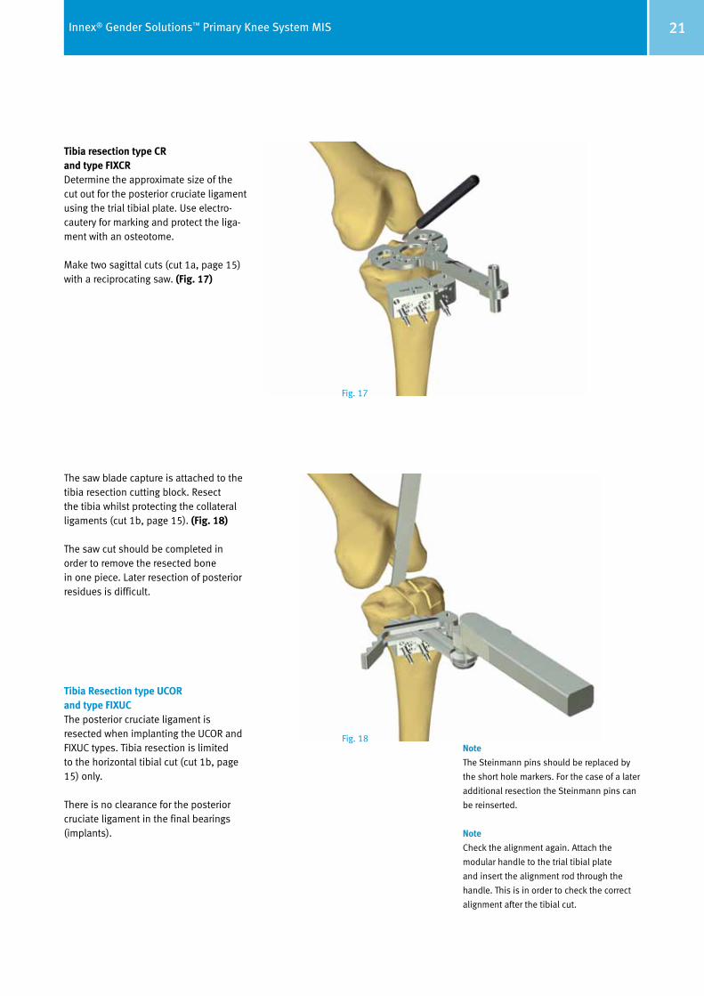
Tibia resection type CR and type FIXCRDetermine the approximate size of the cut out for the posterior cruciate ligament using the trial tibial plate. Use electro-cautery for marking and protect the liga-ment with an osteotome.
Make two sagittal cuts (cut 1a, page 15) with a reciprocating saw. (Fig. 17)
The saw blade capture is attached to the tibia resection cutting block. Resect the tibia whilst protecting the collateral ligaments (cut 1b, page 15). (Fig. 18)
The saw cut should be completed in order to remove the resected bone in one piece. Later resection of posterior residues is difficult.
Tibia Resection type UCOR and type FIXUCThe posterior cruciate ligament is resected when implanting the UCOR and FIXUC types. Tibia resection is limited to the horizontal tibial cut (cut 1b, page 15) only.
There is no clearance for the posterior cruciate ligament in the final bearings (implants).
Fig. 17
Note
The Steinmann pins should be replaced by
the short hole markers. For the case of a later
additional resection the Steinmann pins can
be reinserted.
Note
Check the alignment again. Attach the
modular handle to the trial tibial plate
and insert the alignment rod through the
handle. This is in order to check the correct
alignment after the tibial cut.
Fig. 18

22 Innex® Gender Solutions™ Primary Knee System MIS
Preparation of the Femur Flex the knee 90° to access the femur from the front. Resect osteophytes from both femur and tibia (see handling of the soft tissues, page 14). Perform a pre liminary mediolateral ligament balanc ing. In the minimally invasive technique, it is easier to access the medial com part ment. A modified Z-retrac tor is used to elevate the vastus medi a lis muscle from the distal femur. This facilitates anterior femoral resection and prevents muscle violation.
2. A/P femoral cuts (Cuts 2a and 2b) Opening the medullary canal Osteophytes should have been removed prior to this step.
However, if any osteophytes are still remaining, they should be removed now to facilitate orientation.
Set the femoral intercondylar drill guide on the distal femur above the inter-condylar fossa and drive it in. The align ment must correspond to the longi tudinal axis of the femur in both planes. (Fig. 19–22)
The intercondylar insertion point for the femoral intercondylar drill guide tends to lie slightly medial of the midline. This can be seen in the preoperative A/P X-ray of the femur (long-leg X-ray).
Open the intramedullary space with the 8mm drill. Align the drill with the anatomical axis of the femur. (Fig. 22)
If necessary, the drill can be driven in deeper by removing the drill guide.
Fig. 19correct
Fig. 20incorrect
Fig. 21incorrect
Fig. 22
23Innex® Gender Solutions™ Primary Knee System MIS
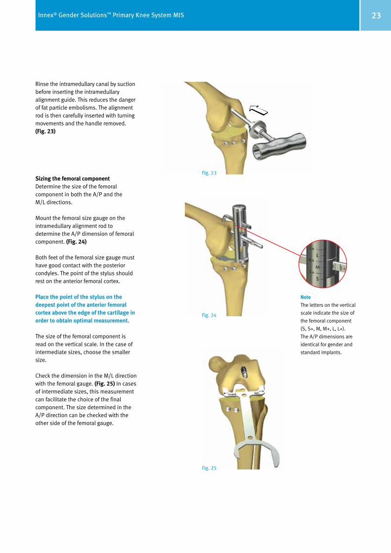
Rinse the intramedullary canal by suction before inserting the intramedullary alignment guide. This reduces the danger of fat particle embolisms. The alignment rod is then carefully inserted with turning movements and the handle removed. (Fig. 23)
Sizing the femoral componentDetermine the size of the femoral com ponent in both the A/P and the M/L directions.
Mount the femoral size gauge on the intramedullary alignment rod to de termine the A/P dimension of femoral component. (Fig. 24)
Both feet of the femoral size gauge must have good contact with the posterior condyles. The point of the stylus should rest on the anterior femoral cortex.
Place the point of the stylus on the deepest point of the anterior femoral cortex above the edge of the cartilage in order to obtain optimal measurement.
The size of the femoral component is read on the vertical scale. In the case of intermediate sizes, choose the smaller size.
Check the dimension in the M/L direction with the femoral gauge. (Fig. 25) In cases of inter mediate sizes, this measurement can facilitate the choice of the final com ponent. The size determined in the A/P direction can be checked with the other side of the femoral gauge.
Note
The letters on the vertical
scale indicate the size of
the femoral component
(S, S+, M, M+, L, L+).
The A/P dimensions are
identical for gender and
standard implants.
Fig. 23
Fig. 24
Fig. 25
24 Innex® Gender Solutions™ Primary Knee System MIS
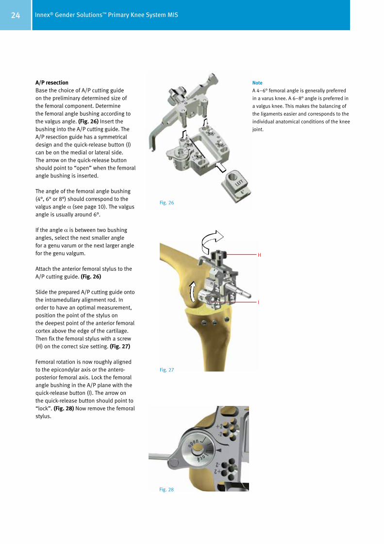
A/P resection Base the choice of A/P cutting guide on the preliminary determined size of the femoral component. Determine the femoral angle bushing according to the valgus angle. (Fig. 26) Insert the bushing into the A/P cutting guide. The A/P resection guide has a symmetrical design and the quick-release button (I) can be on the medial or lateral side. The arrow on the quick-release button should point to “open” when the femoral angle bushing is inserted.
The angle of the femoral angle bushing (4°, 6° or 8°) should correspond to the valgus angle α (see page 10). The valgus angle is usually around 6°.
If the angle α is between two bushing angles, select the next smaller angle for a genu varum or the next larger angle for the genu valgum.
Attach the anterior femoral stylus to the A/P cutting guide. (Fig. 26)
Slide the prepared A/P cutting guide onto the intramedullary alignment rod. In order to have an optimal measurement, position the point of the stylus on the deepest point of the anterior femoral cortex above the edge of the cartilage. Then fix the femoral stylus with a screw (H) on the correct size setting. (Fig. 27)
Femoral rotation is now roughly aligned to the epicondylar axis or the antero-posterior femoral axis. Lock the femoral angle bushing in the A/P plane with the quick-release button (I). The arrow on the quick-release button should point to “lock”. (Fig. 28) Now remove the femoral stylus.
H
I
Fig. 26
Fig. 27
Fig. 28
Note
A 4–6° femoral angle is generally preferred
in a varus knee. A 6–8° angle is preferred in
a valgus knee. This makes the balancing of
the ligaments easier and corresponds to the
individual anatomical conditions of the knee
joint.
25Innex® Gender Solutions™ Primary Knee System MIS
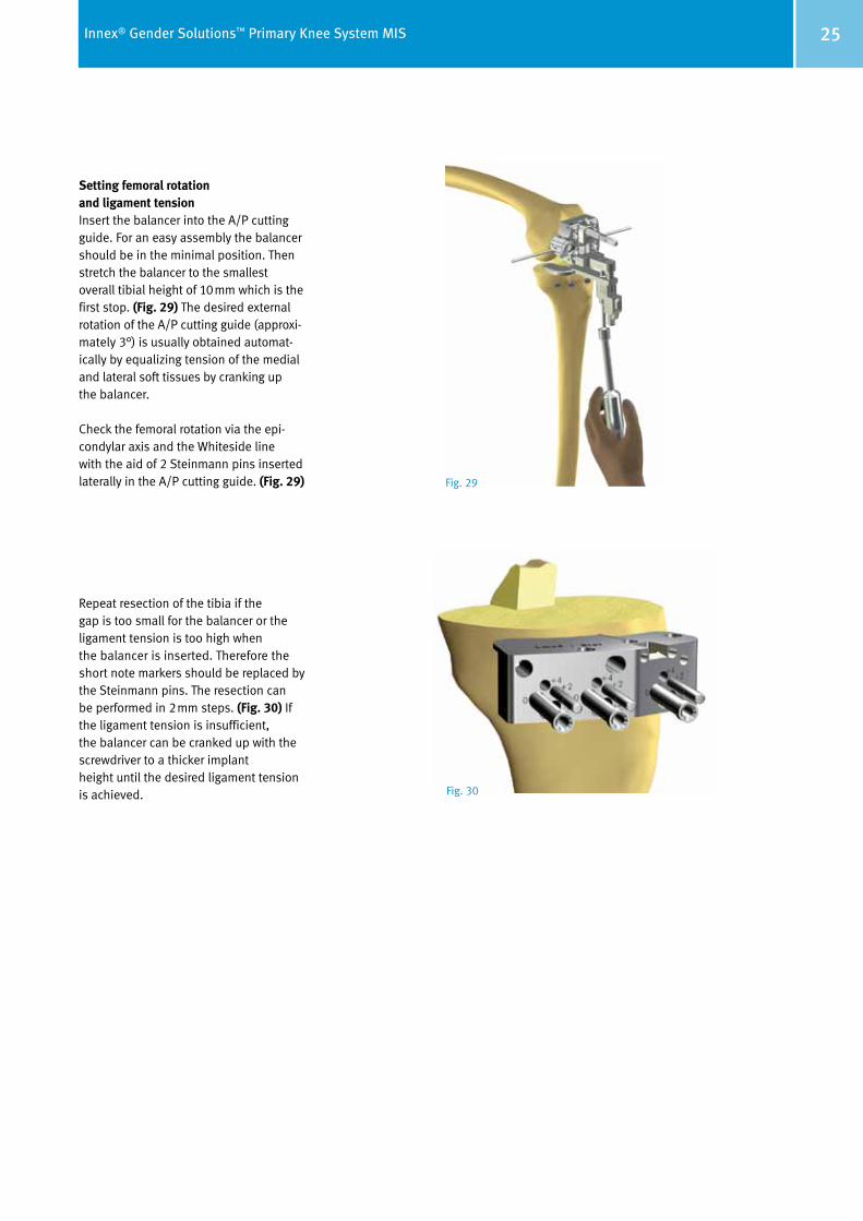
Setting femoral rotation and ligament tension Insert the balancer into the A/P cutting guide. For an easy assembly the balancer should be in the minimal position. Then stretch the balancer to the smallest overall tibial height of 10mm which is the first stop. (Fig. 29) The desired external rotation of the A/P cutting guide (approxi -mately 3°) is usually obtained automat-ically by equalizing tension of the medial and lateral soft tissues by cranking up the balancer.
Check the femoral rotation via the epi-condylar axis and the Whiteside line with the aid of 2 Steinmann pins inserted laterally in the A/P cutting guide. (Fig. 29)
Repeat resection of the tibia if the gap is too small for the balancer or the ligament tension is too high when the balancer is inserted. Therefore the short note markers should be replaced by the Steinmann pins. The resection can be performed in 2mm steps. (Fig. 30) If the ligament tension is insufficient, the balancer can be cranked up with the screwdriver to a thicker implant height until the desired ligament tension is achieved.
Fig. 29
Fig. 30
26 Innex® Gender Solutions™ Primary Knee System MIS
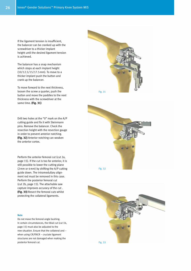
If the ligament tension is insufficient, the balancer can be cranked up with the screwdriver to a thicker implant height until the desired ligament tension is achieved.
The balancer has a snap mechanism which stops at each implant height (10/12.5/15/17.5mm). To move to a thicker implant push the button and crank up the balancer.
To move forward to the next thickness, loosen the screw a quarter, push the button and move the paddles to the next thickness with the screwdriver at the same time. (Fig. 31)
Drill two holes at the “0” mark on the A/P cutting guide and fix it with Steinmann pins. Remove the balancer. Check the resection height with the resection gauge in order to pre vent anterior notching. (Fig. 32) Anterior notching can weaken the anterior cortex.
Perform the anterior femoral cut (cut 2a, page 15). If the cut is too far anterior, it is still possible to lower the cutting plane (2mm or 4mm) by shifting the A/P cutting guide down. The intramedullary align-ment rod must be removed in this case. Perform the posterior femoral cut (cut 2b, page 15). The attachable saw capture improves accuracy of the cut . (Fig. 33) Resect the femoral cuts whilst protecting the collateral ligaments.
Note
Do not move the femoral angle bushing.
In certain circumstances, the tibial cut (cut 1b,
page 15) must also be adjusted to the
new situation. Ensure that the collateral and –
when using CR/FIXCR – cruciate ligament
structures are not damaged when making the
posterior femoral cut.
Fig. 31
Fig. 32
Fig. 33
27Innex® Gender Solutions™ Primary Knee System MIS
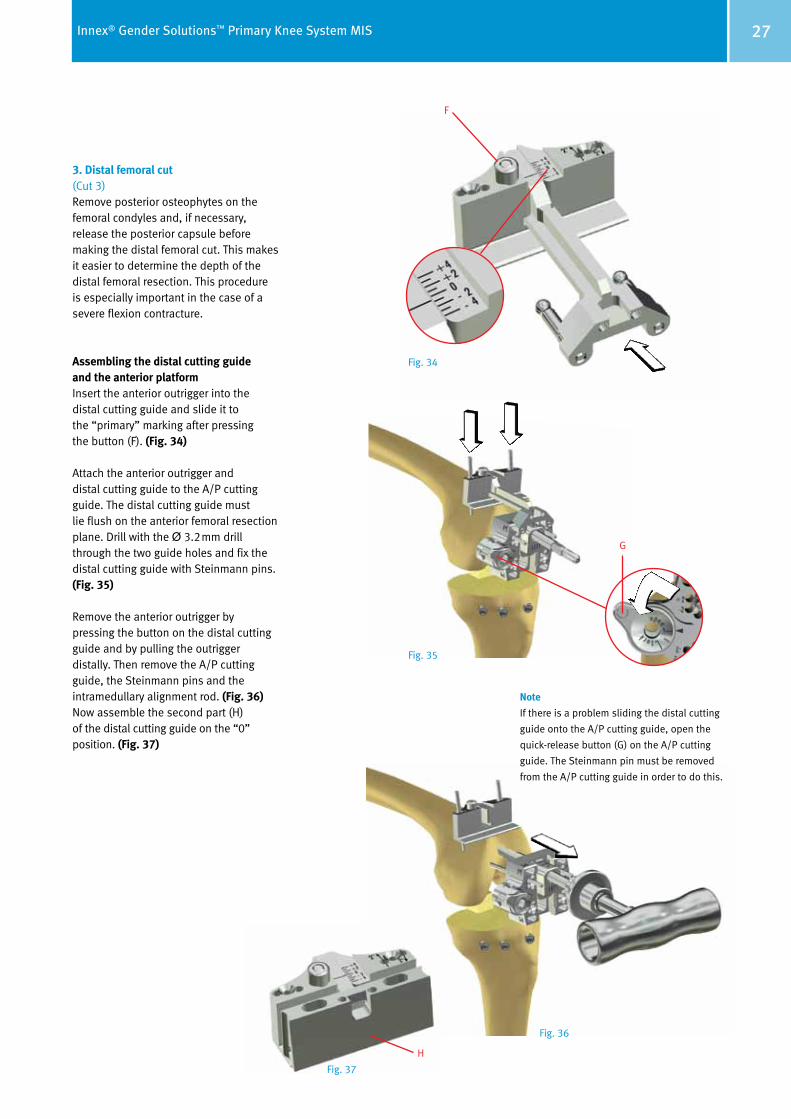
3. Distal femoral cut (Cut 3)Remove posterior osteophytes on the femoral condyles and, if necessary, release the posterior capsule before making the distal femoral cut. This makes it easier to determine the depth of the distal femoral resection. This procedure is especially important in the case of a severe flexion contracture.
Assembling the distal cutting guide and the anterior platformInsert the anterior outrigger into the distal cutting guide and slide it to the “primary” marking after pressing the button (F). (Fig. 34)
Attach the anterior outrigger and distal cutting guide to the A/P cutting guide. The distal cutting guide must lie flush on the anterior femoral resection plane. Drill with the Ø 3.2mm drill through the two guide holes and fix the distal cutting guide with Stein mann pins. (Fig. 35)
Remove the anterior outrigger by pressing the button on the distal cutting guide and by pulling the outrigger distally. Then remove the A/P cutting guide, the Steinmann pins and the intramedullary alignment rod. (Fig. 36) Now assemble the second part (H) of the distal cutting guide on the “0” position. (Fig. 37)
Note
If there is a problem sliding the distal cutting
guide onto the A/P cutting guide, open the
quick-release button (G) on the A/P cutting
guide. The Steinmann pin must be removed
from the A/P cutting guide in order to do this.
F
G
Fig. 34
Fig. 35
Fig. 36
Fig. 37
H
28 Innex® Gender Solutions™ Primary Knee System MIS
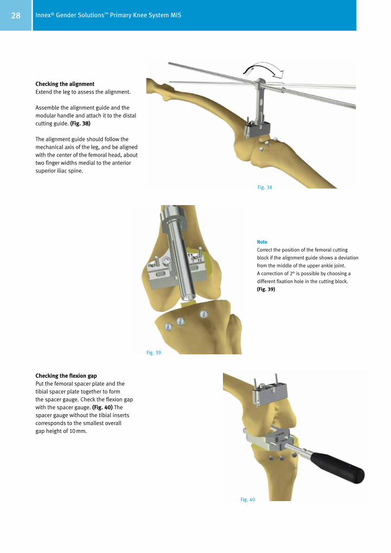
Checking the alignment Extend the leg to assess the alignment.
Assemble the alignment guide and the modular handle and attach it to the distal cutting guide. (Fig. 38)
The alignment guide should follow the mechanical axis of the leg, and be aligned with the center of the femoral head, about two finger widths medial to the anterior superior iliac spine.
Checking the flexion gapPut the femoral spacer plate and the tibial spacer plate together to form the spacer gauge. Check the flexion gap with the spacer gauge. (Fig. 40) The spacer gauge without the tibial inserts corresponds to the smallest overall gap height of 10mm.
Note
Correct the position of the femoral cutting
block if the alignment guide shows a deviation
from the middle of the upper ankle joint.
A correction of 2° is possible by choosing a
different fixation hole in the cutting block.
(Fig. 39)
Fig. 38
Fig. 39
Fig. 40
29Innex® Gender Solutions™ Primary Knee System MIS
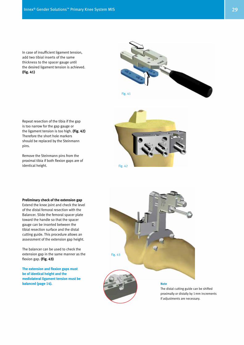
In case of insufficient ligament tension, add two tibial inserts of the same thickness to the spacer gauge until the desired ligament tension is achieved. (Fig. 41)
Repeat resection of the tibia if the gap is too narrow for the gap gauge or the ligament tension is too high. (Fig. 42) Therefore the short hole markers should be replaced by the Steinmann pins.
Remove the Steinmann pins from the proximal tibia if both flexion gaps are of identical height.
Preliminary check of the extension gapExtend the knee joint and check the level of the distal femoral resection with the Balancer. Slide the femoral spacer plate toward the handle so that the spacer gauge can be inserted between the tibial resection surface and the distal cutting guide. This procedure allows an assessment of the extension gap height.
The balancer can be used to check the extension gap in the same manner as the flexion gap. (Fig. 43)
The extension and flexion gaps must be of identical height and the mediolateral ligament tension must be balanced (page 14). Note
The distal cutting guide can be shifted
proximally or distally by 1mm increments
if adjustments are necessary.
Fig. 41
Fig. 42
Fig. 43
30 Innex® Gender Solutions™ Primary Knee System MIS
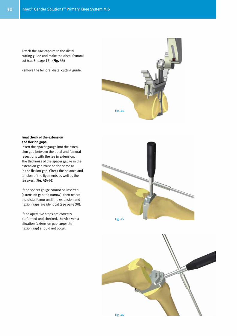
Attach the saw capture to the distal cutting guide and make the distal femoral cut (cut 3, page 15). (Fig. 44)
Remove the femoral distal cutting guide.
Final check of the extension and flexion gapsInsert the spacer gauge into the exten-sion gap between the tibial and femoral resections with the leg in extension. The thickness of the spacer gauge in the extension gap must be the same as in the flexion gap. Check the balance and tension of the ligaments as well as the leg axes. (Fig. 45/46)
If the spacer gauge cannot be inserted (extension gap too narrow), then resect the distal femur until the extension and flexion gaps are identical (see page 30).
If the operative steps are correctly performed and checked, the vice-versa situation (extension gap larger than flexion gap) should not occur.
Fig. 44
Fig. 45
Fig. 46
31Innex® Gender Solutions™ Primary Knee System MIS
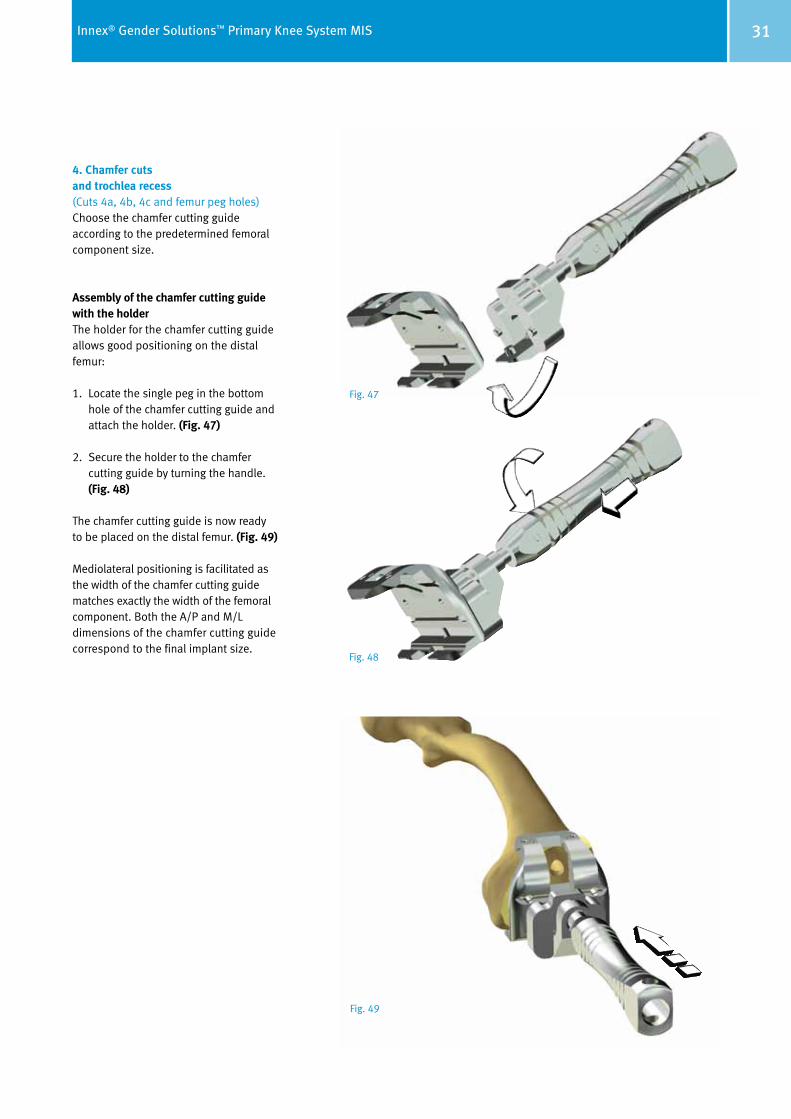
4. Chamfer cuts and trochlea recess (Cuts 4a, 4b, 4c and femur peg holes)Choose the chamfer cutting guide according to the predetermined femoral component size.
Assembly of the chamfer cutting guide with the holderThe holder for the chamfer cutting guide allows good positioning on the distal femur:
1. Locate the single peg in the bottom hole of the chamfer cutting guide and attach the holder. (Fig. 47)
2. Secure the holder to the chamfer cutting guide by turning the handle. (Fig. 48)
The chamfer cutting guide is now ready to be placed on the distal femur. (Fig. 49)
Mediolateral positioning is facilitated as the width of the chamfer cutting guide matches exactly the width of the femoral component. Both the A/P and M/L dimensions of the chamfer cutting guide correspond to the final implant size.
Fig. 47
Fig. 49
Fig. 48
32 Innex® Gender Solutions™ Primary Knee System MIS
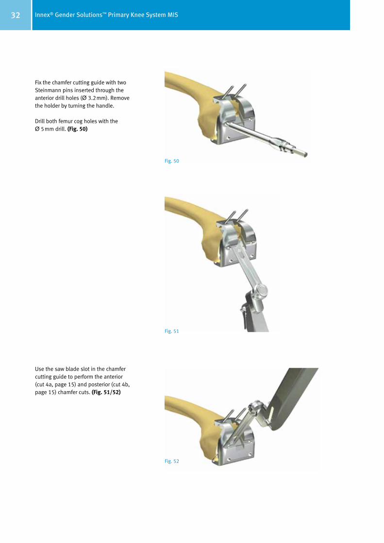
Fix the chamfer cutting guide with two Steinmann pins inserted through the anterior drill holes (Ø 3.2mm). Remove the holder by turning the handle.
Drill both femur cog holes with the Ø 5mm drill. (Fig. 50)
Use the saw blade slot in the chamfer cutting guide to perform the anterior (cut 4a, page 15) and posterior (cut 4b, page 15) chamfer cuts. (Fig. 51/52)
Fig. 50
Fig. 51
Fig. 52

33Innex® Gender Solutions™ Primary Knee System MIS
Prepare the trochlea recess of the femoral component using a jigsaw and corresponding osteotome (15mm). (Fig. 53)
Bring the knee joint into maximum flexion and remove the remaining poste-rior osteophytes with a curved osteotome or oscillating saw (cut 4c). The posterior edge of the chamfer cutting guide serves as a reference. (Fig. 54) Avoid damaging the posterior femoral cortex.Be careful not to harm the popliteal neurovascular structures.
Take out the Steinmann pins and then remove the chamfer cutting guide with the extractor. (Fig. 55)
Note
The chamfer cutting guide protects the
mediolateral soft tissues by capturing the saw
blade inside. Therefore it could be necessary
to finish the cuts after removing the chamfer
cutting guide.
Fig. 53
Fig. 54
Fig. 55
34 Innex® Gender Solutions™ Primary Knee System MIS
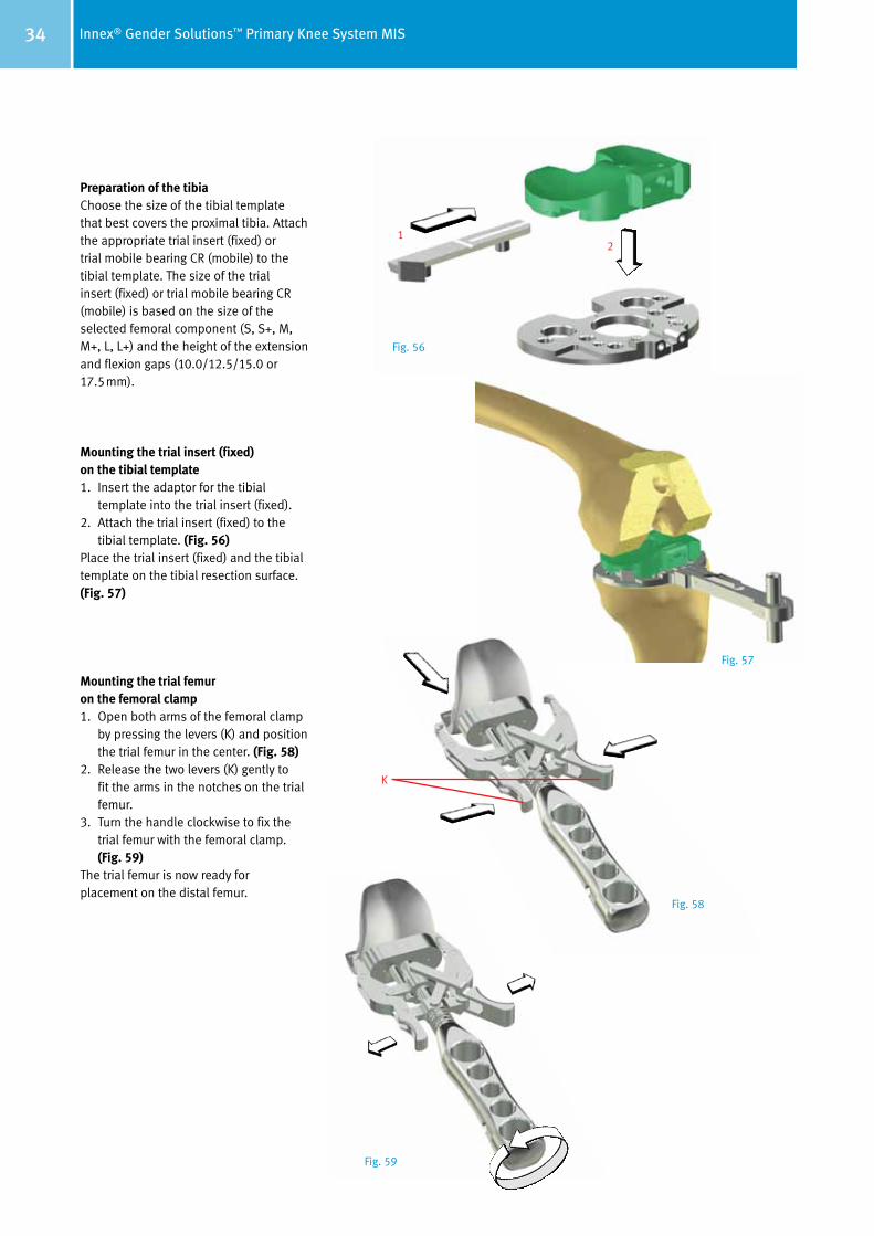
Preparation of the tibiaChoose the size of the tibial template that best covers the proximal tibia. Attach the appropriate trial insert (fixed) or trial mobile bearing CR (mobile) to the tibial template. The size of the trial insert (fixed) or trial mobile bearing CR (mobile) is based on the size of the selected femoral component (S, S+, M, M+, L, L+) and the height of the extension and flexion gaps (10.0/12.5/15.0 or 17.5mm).
Mounting the trial insert (fixed) on the tibial template1. Insert the adaptor for the tibial
template into the trial insert (fixed). 2. Attach the trial insert (fixed) to the
tibial template. (Fig. 56)Place the trial insert (fixed) and the tibial template on the tibial resection surface. (Fig. 57)
Mounting the trial femur on the femoral clamp1. Open both arms of the femoral clamp
by pressing the levers (K) and position the trial femur in the center. (Fig. 58)
2. Release the two levers (K) gently to fit the arms in the notches on the trial femur.
3. Turn the handle clockwise to fix the trial femur with the femoral clamp. (Fig. 59)
The trial femur is now ready for placement on the distal femur.
12
K
Fig. 56
Fig. 57
Fig. 58
Fig. 59

35Innex® Gender Solutions™ Primary Knee System MIS
Use the femoral clamp to mount the trial femur of the appropriate size on the femur. (Fig. 60) Uncouple the femoral clamp from the trial femur by turning the handle counterclockwise and pressing the levers together.
Use the impactor to drive in the trial femur until optimal bone contact is achieved. (Fig. 61)
Setting tibial rotationThe trial tibia is automatically rotated into the final position by repeated flexion and extension of the knee joint while maintaining optimum tibia coverage. (Fig. 62/63)
When using the mobile bearing, the tibial template can be fixed for best coverage without having to pre- set rotation.
Note
A high anterior resistance can occur when
driving in the trial femur. This resistance can
be overcome by applying extension force.
This leads to a neutral position of the trial
femur and prevents misplacement in flexion.
Note
The movement of the prosthesis during
flexion and extension can be checked at the
same time.
Fig. 60
Fig. 61
Fig. 62
Fig. 63

36 Innex® Gender Solutions™ Primary Knee System MIS
Extend the knee and fix the tibial tem-plate with two Steinmann pins. (Fig. 64) It is recom mended to mark the position of the trial tibia with a cautery. (Fig. 65) These markings represent an additional aid for position ing the definitive tibia component. This is especially useful for a cemented tibia component.
Remove the trial insert (fixed) or trial mobile bearing (mobile) and the trial femur.
Place the tibia impactor guide on the tibial gauge, assemble it with the modular handle and drill the peg holes (Ø 5mm). (Fig. 66)
Then drill the central tibial stem hole with a Ø 18.5mm step drill until it can not go any further. (Fig. 66)
Prepare the tibial stem fins by com-pressing the cancellous bone with the tibial impactor. (Fig. 67)
Remove the Steinmann pins, the tibia impactor guide and the tibial template.
Note
If necessary the tibial template can be further
stabilized with two additional Steinmann pins.
Note
Ensure that the locating pin on the tibial
im pactor is inserted into the posterior channel
of the tibia impactor guide!
Fig. 64 Fig. 65
Fig. 66
Fig. 67
37Innex® Gender Solutions™ Primary Knee System MIS
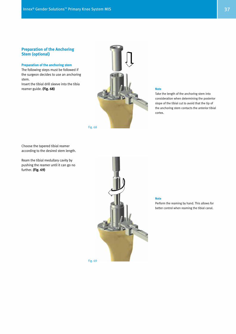
Preparation of the Anchoring Stem (optional)
Preparation of the anchoring stem The following steps must be followed if the surgeon decides to use an anchoring stem.Insert the tibial drill sleeve into the tibia reamer guide. (Fig. 68)
Choose the tapered tibial reamer according to the desired stem length.
Ream the tibial medullary cavity by pushing the reamer until it can go no further. (Fig. 69)
Note
Take the length of the anchoring stem into
consideration when determining the posterior
slope of the tibial cut to avoid that the tip of
the anchoring stem contacts the anterior tibial
cortex.
Note
Perform the reaming by hand. This allows for
better control when reaming the tibial canal.
Fig. 68
Fig. 69

38 Innex® Gender Solutions™ Primary Knee System MIS
Positioning the Trial Components
Trial assembly Assembly of the trial tibia plateau with the tibial clamp A special tibial clamp is provided for simple and accurate positioning of the trial tibia plateau.
1. Position the tibial adaptor (labeled: “Tibial Trial”) in the hole of the trial tibia plateau and fix with the screw (L). (Fig. 70)
2. Then slide the tibial clamp from the front onto the tibial adaptor. (Fig. 71)
3. Fix the tibial clamp by tightening the screw. (Fig. 72)
The trial tibia plateau is now ready for insertion.
Depending on the type of prosthesis, insert the mobile or fixed bearing in the following manner:
Type CR Insert the corresponding guide pin into the trial meniscal bearing (mobile). Ensure that the guide pin is correctly aligned (ANT). Then insert both parts into the trial tibia plateau. (Fig. 73)
Type UCOR Insert the trial mobile bearing into the trial tibia plateau. (Fig. 74)
Type FIX Insert the adapter fot the tibial gauge (S, M, L) into the trial insert (fixed).Insert the trial fixed bearing into the trial tibia plateau. (Fig. 75)
L
CR
FIX
UCOR
Fig. 70 Fig. 71 Fig. 72
Fig. 73
Fig. 75
Fig. 74Note – CombinationThe combination matrix are displayed on page 48 (mobile) and 49 (fixed).
39Innex® Gender Solutions™ Primary Knee System MIS
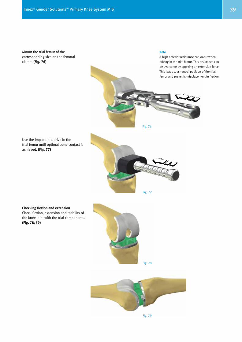
Mount the trial femur of the corresponding size on the femoral clamp. (Fig. 76)
Use the impactor to drive in the trial femur until optimal bone contact is achieved. (Fig. 77)
Checking flexion and extension Check flexion, extension and stability of the knee joint with the trial components. (Fig. 78/79)
Note
A high anterior resistance can occur when
driving in the trial femur. This resistance can
be overcome by applying an extension force.
This leads to a neutral position of the trial
femur and prevents misplacement in flexion.
Fig. 76
Fig. 77
Fig. 78
Fig. 79
40 Innex® Gender Solutions™ Primary Knee System MIS
Procedure when preserving the patella
In minimally invasive surgery the leg is extended and the patella is tilted 90° upward.
It is not necessary to replace the patella due to the anatomical nature of the trochlear recess of the femoral compo-nent.
If the surgeon decides not to replace the patella, it is recommended to per form a patellaplasty1. The patella-plasty consists of the following steps:
• Perform circumferential denervation of the synovial edge of the patella with electrocautery
• Remove peripheral osteophytes to restore the patella to its normal shape and size.
Be careful not to damage tendon inser-tions on the bone. Measure the thickness of the patella with the caliper. Determine the amount of bone that should remain after resection by subtracting the implant thickness from the patella thickness.
1 P. Keblish et al., JBJS, Vol. 76-B, 1994, Nr. 6: 930–937
Preparation of the Patella (optional)
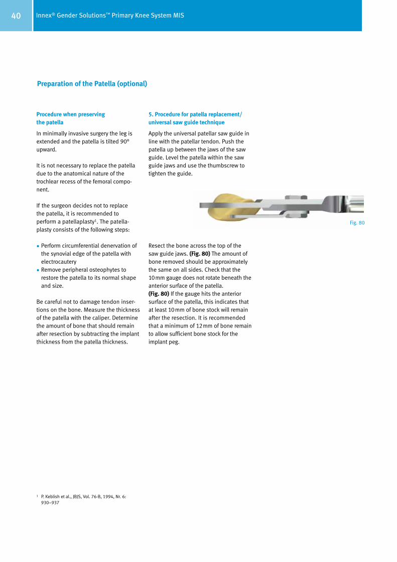
5. Procedure for patella replacement/ universal saw guide technique
Apply the universal patellar saw guide in line with the patellar tendon. Push the patella up between the jaws of the saw guide. Level the patella within the saw guide jaws and use the thumbscrew to tighten the guide.
Resect the bone across the top of the saw guide jaws. (Fig. 80) The amount of bone removed should be approximately the same on all sides. Check that the 10mm gauge does not rotate beneath the anterior surface of the patella. (Fig. 80) If the gauge hits the anterior surface of the patella, this indicates that at least 10mm of bone stock will remain after the resection. It is recommended that a minimum of 12mm of bone remain to allow sufficient bone stock for the implant peg.
Fig. 80
41Innex® Gender Solutions™ Primary Knee System MIS
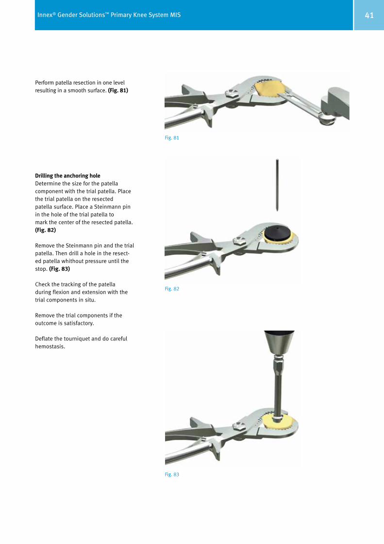
Perform patella resection in one level resulting in a smooth surface. (Fig. 81)
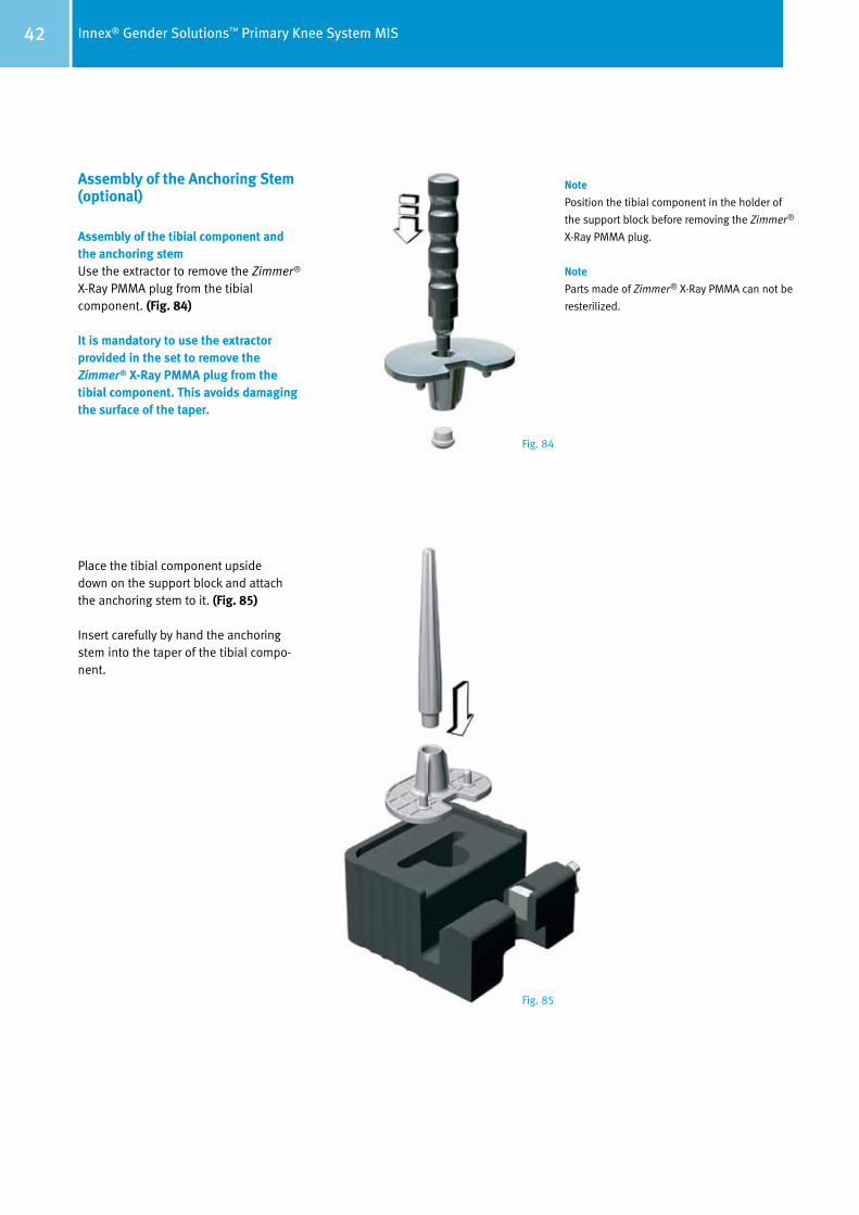
Drilling the anchoring holeDetermine the size for the patella component with the trial patella. Place the trial patella on the resected patella surface. Place a Steinmann pin in the hole of the trial patella to mark the center of the resected patella. (Fig. 82)
Remove the Steinmann pin and the trial patella. Then drill a hole in the resect-ed patella whithout pressure until the stop. (Fig. 83)
Check the tracking of the patella during flexion and extension with the trial components in situ.
Remove the trial components if the outcome is satisfactory.
Deflate the tourniquet and do careful hemostasis.
Fig. 81
Fig. 82
Fig. 83
42 Innex® Gender Solutions™ Primary Knee System MIS
Assembly of the Anchoring Stem (optional)
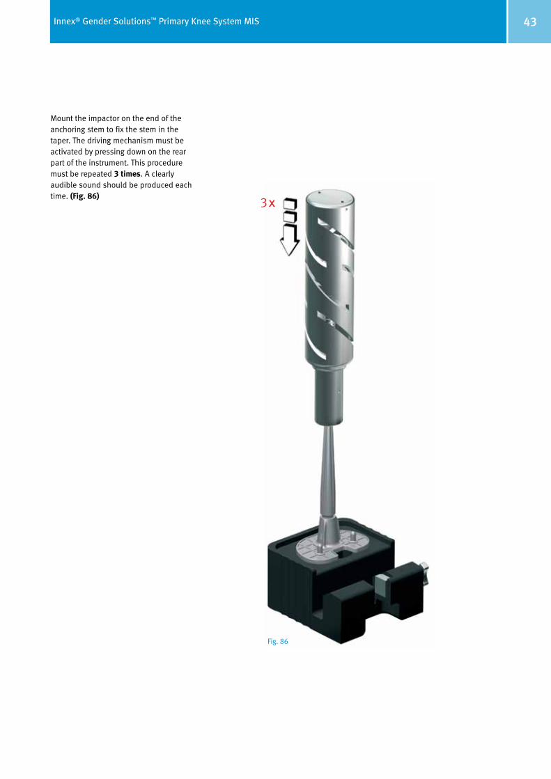
Assembly of the tibial component and the anchoring stemUse the extractor to remove the Zimmer® X-Ray PMMA plug from the tibial component. (Fig. 84)
It is mandatory to use the extractor provided in the set to remove the Zimmer® X-Ray PMMA plug from the tibial component. This avoids damaging the surface of the taper.
Place the tibial component upside down on the support block and attach the anchoring stem to it. (Fig. 85)
Insert carefully by hand the anchoring stem into the taper of the tibial compo-nent.
Note
Position the tibial component in the holder of
the support block before removing the Zimmer®
X-Ray PMMA plug.
Note
Parts made of Zimmer® X-Ray PMMA can not be
resterilized.
Fig. 84
Fig. 85
43Innex® Gender Solutions™ Primary Knee System MIS
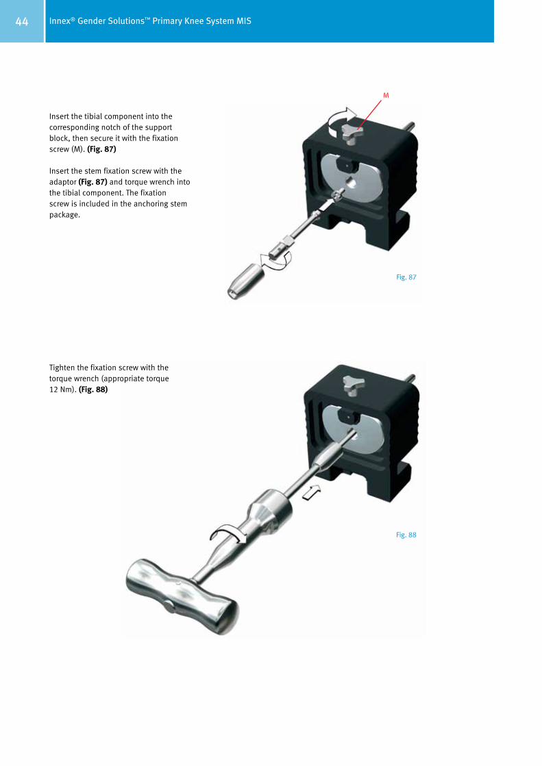
Mount the impactor on the end of the anchoring stem to fix the stem in the taper. The driving mechanism must be activated by pressing down on the rear part of the instrument. This procedure must be repeated 3 times. A clearly audible sound should be produced each time. (Fig. 86)
3x
Fig. 86
44 Innex® Gender Solutions™ Primary Knee System MIS
Insert the tibial component into the corresponding notch of the support block, then secure it with the fixation screw (M). (Fig. 87)
Insert the stem fixation screw with the adap tor (Fig. 87) and torque wrench into the tibial component. The fixation screw is in cluded in the anchoring stem package.
Tighten the fixation screw with the torque wrench (appropriate torque 12 Nm). (Fig. 88)
M
Fig. 87
Fig. 88
45Innex® Gender Solutions™ Primary Knee System MIS
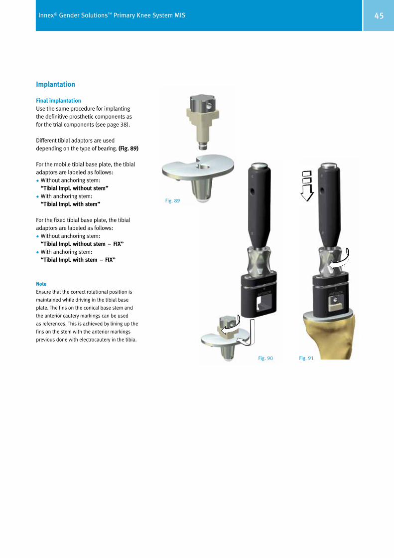
Implantation
Final implantationUse the same procedure for implanting the definitive prosthetic components as for the trial components (see page 38).
Different tibial adaptors are used depending on the type of bearing. (Fig. 89)
For the mobile tibial base plate, the tibial adaptors are labeled as follows:
• Without anchoring stem: “Tibial Impl. without stem”
• With anchoring stem: “Tibial Impl. with stem”
For the fixed tibial base plate, the tibial adaptors are labeled as follows:
• Without anchoring stem: “Tibial Impl. without stem – FIX”
• With anchoring stem: “Tibial Impl. with stem – FIX”
Note
Ensure that the correct rotational position is
maintained while driving in the tibial base
plate. The fins on the conical base stem and
the anterior cautery markings can be used
as references. This is achieved by lining up the
fins on the stem with the anterior markings
previous done with electrocautery in the tibia.
Fig. 89
Fig. 90 Fig. 91
46 Innex® Gender Solutions™ Primary Knee System MIS
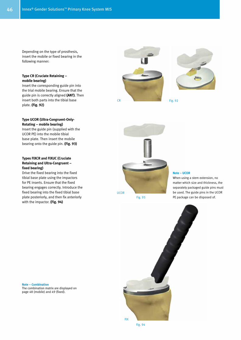
Depending on the type of prosthesis, insert the mobile or fixed bearing in the following manner:
Type CR (Cruciate Retaining – mobile bearing)Insert the corresponding guide pin into the trial mobile bearing. Ensure that the guide pin is correctly aligned (ANT). Then insert both parts into the tibial base plate. (Fig. 92)
Type UCOR (Ultra-Congruent-Only-Rotating – mobile bearing)Insert the guide pin (supplied with the UCOR PE) into the mobile tibial base plate. Then insert the mobile bearing onto the guide pin. (Fig. 93)
Types FIXCR and FIXUC (Cruciate Retaining and Ultra-Congruent – fixed bearing)Drive the fixed bearing into the fixed tibial base plate using the impactors for PE inserts. Ensure that the fixed bearing engages correctly. Introduce the fixed bearing into the fixed tibial base plate posteriorly, and then fix anteriorly with the impactor. (Fig. 94)
Note – UCOR
When using a stem extension, no
matter which size and thickness, the
separately packaged guide pins must
be used. The guide pins in the UCOR
PE package can be disposed of. UCOR
FIX
CR Fig. 92
Fig. 93
Fig. 94
Note – CombinationThe combination matrix are displayed on page 48 (mobile) and 49 (fixed).
47Innex® Gender Solutions™ Primary Knee System MIS
Notes on the cemented version
Apply cement in the cement pockets only under
the mobile tibial base plate or under the fixed
tibial base plate. Do not apply any cement
in the area of the central tibial anchoring peg!
It is recommended not to implant the femoral
component until the cement has hardened on
the tibia.
However, if inserting both components in one
cementing procedure, a very careful technique
is important, because cement residues cannot
be removed from the posterior recess.
The advantage of inserting both components
in one cementing procedure is that pressure is
applied during polymerization of the cement.
Due to the fast setting of the cement it is
recommended to insert the patella component
as the first step or in a separate cementing
procedure after having fixed tibial and femoral
components.
Remove all excess cement and any loose
cement particles to avoid damage to the
surfaces of the prosthesis (third body wear).
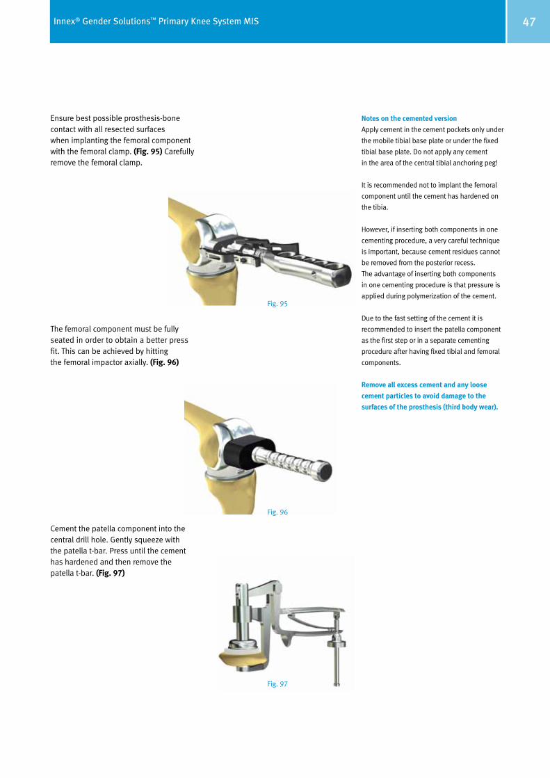
Ensure best possible prosthesis-bone contact with all resected surfaces when implanting the femoral component with the femoral clamp. (Fig. 95) Carefully remove the femoral clamp.
The femoral component must be fully seated in order to obtain a better press fit. This can be achieved by hitting the femoral impactor axially. (Fig. 96)
Cement the patella component into the central drill hole. Gently squeeze with the patella t-bar. Press until the cement has hardened and then remove the patella t-bar. (Fig. 97)
Fig. 95
Fig. 96
Fig. 97

48 Innex® Gender Solutions™ Primary Knee System MIS
CR
(Cru
ciat
e Re
tain
ing)
whe
n re
tain
ing
the
post
erio
r cru
ciat
e lig
amen
t U
COR
(Ult
ra-C
ongr
uent
-Onl
y-Ro
tati
ng) w
hen
rese
ctin
g th
e po
ster
ior c
ruci
ate
ligam
ent
Combination Table of the Mobile Bearing System
Fem
oral
com
pone
nt
left
/rig
ht C
R (G
ende
r Sol
utio
ns™
)(1 c
emen
ted,
2 unc
emen
ted)
Fem
oral
com
pone
nt le
ft/r
ight
CR
(1 cem
ente
d, 2 u
ncem
ente
d)
SS
+M
M +
LL +
Zim
mer
Inne
x® K
nee
Syst
em
Mob
ile B
eari
ng
Mob
ile B
eari
ng(C
R, U
COR)
Gui
de p
in(C
R)
Tibi
al b
asep
late
, mob
ile(1 c
emen
ted,
2 unc
emen
ted)
SM
LCR
UCO
RCR
UCO
RCR
UCO
R
Con-
100
01.0
2001
.471
01.0
2001
.417
Gui
de p
in, U
COR
Anch
orag
e st
em, c
onic
al
01.0
2001
.419
Siz
e 15
/17.
501
.020
01.4
18S
ize
10/1
2.5
12
34
56
7
0–2
3–5
6–8
2
701
.020
01.3
00
31
01.0
2001
.301
3
501
.020
01.3
02
39
01.0
2001
.303
Pate
llar c
ompo
nent
1 01.
0200
1.00
72 0
1.02
001.
019
1 01.
0200
1.08
82 0
1.02
001.
099
1 01.
0200
1.08
72 0
1.02
001.
098
1 01.
0200
1.08
62 0
1.02
001.
097
1 01.
0200
1.08
52 0
1.02
001.
096
1 01.
0200
1.08
42 0
1.02
001.
095
1 01.
0200
1.00
12 0
1.02
001.
013
1 01.
0200
1.07
42 0
1.02
001.
090
1 01.
0200
1.07
52 0
1.02
001.
091
1 01.
0200
1.07
62 0
1.02
001.
092
1 01.
0200
1.07
72 0
1.02
001.
093
1 01.
0200
1.07
82 0
1.02
001.
094
1 01.
0200
1.00
22 0
1.02
001.
014
1 01.
0200
1.00
32 0
1.02
001.
015
1 01.
0200
1.00
42 0
1.02
001.
016
1 01.
0200
1.00
52 0
1.02
001.
017
1 01.
0200
1.00
62 0
1.02
001.
018
1 01.
0200
1.01
22 0
1.02
001.
024
1 01.
0200
1.01
12 0
1.02
001.
023
1 01.
0200
1.00
92 0
1.02
001.
021
1 01.
0200
1.00
82 0
1.02
001.
020
1 01.
0200
1.01
02 0
1.02
001.
022
12.5
01.
0200
1.20
2
15
01.0
2001
.203
10
01.0
2001
.201
10
01.0
2001
.352
12.5
01.
0200
1.35
3
15
01.0
2001
.354
17.5
01.
0200
1.35
5
10
01.0
2001
.205
12.5
01.
0200
1.20
6
15
01.0
2001
.207
10
01.0
2001
.356
12.5
01.
0200
1.35
7
15
01.0
2001
.358
17.5
01.
0200
1.35
9
12.5
01.
0200
1.21
0
15
01.0
2001
.211
10
01.0
2001
.360
12.5
01.
0200
1.36
1
15
01.0
2001
.362
17.5
01.
0200
1.36
3
1 01.
0200
1.13
22 0
1.02
001.
162
1 01.
0200
1.13
32 0
1.02
001.
163
1 01.
0200
1.13
42 0
1.02
001.
164
1 01.
0200
1.13
52 0
1.02
001.
165
1 01.
0200
1.13
62 0
1.02
001.
166
1 01.
0200
1.13
72 0
1.02
001.
167
1 01.
0200
1.13
12 0
1.02
001.
161
01.0
2001
.415
01.0
2001
.416
Con-
5001
.020
01.4
70
10
01.0
2001
.209
49Innex® Gender Solutions™ Primary Knee System MIS
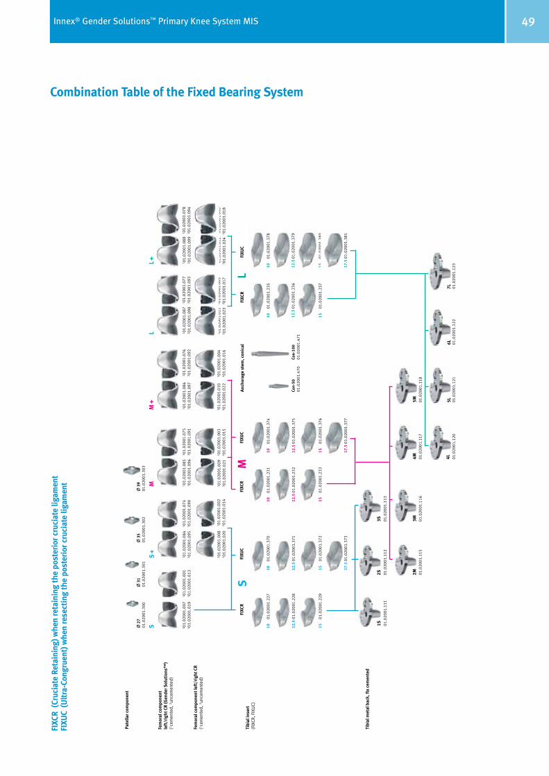
Combination Table of the Fixed Bearing System
FIXC
R (C
ruci
ate
Reta
inin
g) w
hen
reta
inin
g th
e po
ster
ior c
ruci
ate
ligam
ent
FIXU
C (U
ltra
-Con
grue
nt) w
hen
rese
ctin
g th
e po
ster
ior c
ruci
ate
ligam
ent
Fem
oral
com
pone
nt
left
/rig
ht C
R (G
ende
r Sol
utio
ns™
)(1 c
emen
ted,
2 unc
emen
ted)
Fem
oral
com
pone
nt le
ft/r
ight
CR
(1 cem
ente
d, 2 u
ncem
ente
d)
SS
+M
M +
LL +
Zim
mer
Inne
x® K
nee
Syst
em
Fixe
d B
eari
ng
Tibi
al in
sert
(FIX
CR, F
IXU
C)
Tibi
al m
etal
bac
k, fi
x ce
men
ted
SM
LFI
XCR
FIXU
CFI
XCR
FIXU
CFI
XCR
FIXU
CAn
chor
age
stem
, con
ical
Pate
llar c
ompo
nent
2
701
.020
01.3
00
31
01.0
2001
.301
3
501
.020
01.3
02
39
01.0
2001
.303
17.5
01.
0200
1.37
3
1 01.
0200
1.00
72 0
1.02
001.
019
1 01.
0200
1.08
82 0
1.02
001.
099
1 01.
0200
1.08
72 0
1.02
001.
098
1 01.
0200
1.08
62 0
1.02
001.
097
1 01.
0200
1.08
52 0
1.02
001.
096
1 01.
0200
1.08
42 0
1.02
001.
095
1 01.
0200
1.00
12 0
1.02
001.
013
1 01.
0200
1.07
42 0
1.02
001.
090
1 01.
0200
1.07
52 0
1.02
001.
091
1 01.
0200
1.07
62 0
1.02
001.
092
1 01.
0200
1.07
72 0
1.02
001.
093
1 01.
0200
1.07
82 0
1.02
001.
094
1 01.
0200
1.00
22 0
1.02
001.
014
1 01.
0200
1.00
82 0
1.02
001.
020
1 01.
0200
1.00
32 0
1.02
001.
015
1 01.
0200
1.00
42 0
1.02
001.
016
1 01.
0200
1.00
52 0
1.02
001.
017
1 01.
0200
1.00
62 0
1.02
001.
018
1 01.
0200
1.01
22 0
1.02
001.
024
1 01.
0200
1.01
12 0
1.02
001.
023
1 01.
0200
1.00
92 0
1.02
001.
021
1 01.
0200
1.01
02 0
1.02
001.
022
Con-
5001
.020
01.4
70Co
n-10
001
.020
01.4
71
10
01.0
2001
.227
12.5
01.
0200
1.22
8
15
01.0
2001
.229
10
01.0
2001
.370
12.5
01.
0200
1.37
1
15
01.0
2001
.372
10
01.0
2001
.231
12.5
01.
0200
1.23
2
15
01.0
2001
.233
10
01.0
2001
.374
12.5
01.
0200
1.37
5
15
01.0
2001
.376
17.5
01.
0200
1.37
7
10
01.0
2001
.235
12.5
01.
0200
1.23
6
15
01.0
2001
.237
10
01.0
2001
.378
12.5
01.
0200
1.37
9
15
01.0
2001
.380
17.5
01.
0200
1.38
1
6L7L
01.0
2001
.122
01.0
2001
.123
5L4L 01
.020
01.1
2001
.020
01.1
21
2M3M
4M5M
01.0
2001
.115
01.0
2001
.116
01.0
2001
.117
01.0
2001
.118
01.0
2001
.111
01.0
2001
.112
01.0
2001
.113
1S2S
3S

+H84406015200121/$110503E11P
Lit.-Nr. 06.01520.012 – Ed. 2011-05 ZHUB
Contact your Zimmer representative or visit us at www.zimmer.com
Copy
righ
t 201
1 by
Zim
mer
Gm
bH
Prin
ted
in S
wit
zerla
nd
Subj
ect t
o ch
ange
wit
hout
not
ice
Disclaimer
This documentation is intended exclusively for physicians and is not intended for laypersons. Information on the products and procedures contained in this document is of a general nature and does not represent and does not constitute medical advice or recommendations. Because this information does not purport to constitute any diagnostic or therapeutic statement with regard to any individual medical case, each patient must be examined and advised individually, and this document does not replace the need for such examination and/or advice in whole or in part.
Please refer to the package inserts for important product information, including, but not limited to, contraindications, warnings, precautions, and adverse effects.