Embed Size (px)
Citation preview
Suppress Your Surges:Surge Suppression Fundamentals
April 13, 2017
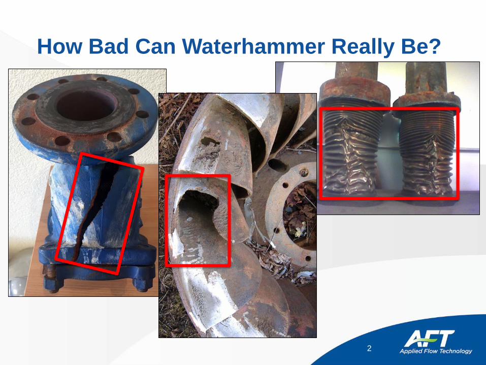
How Bad Can Waterhammer Really Be?
2
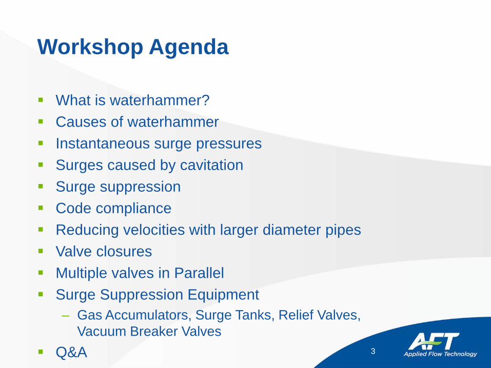
Workshop Agenda
What is waterhammer? Causes of waterhammer Instantaneous surge pressures Surges caused by cavitation Surge suppression Code compliance Reducing velocities with larger diameter pipes Valve closures Multiple valves in Parallel Surge Suppression Equipment
– Gas Accumulators, Surge Tanks, Relief Valves, Vacuum Breaker Valves
Q&A 3
What is Waterhammer?
Waterhammer – transient phenomenon occurring in liquid pipe systems when an event causes steady-state departure
Waterhammer is the process the piping system experiences as it adjusts to the new conditions
Waterhammer can be caused by many events including– Valve closure or opening (in full or in part)– Pump speed change– Relief valves & check valves opening/closing– Control valves responding to system transients– Tank pressurization– Periodic pressure or flow conditions
AFT Impulse models waterhammer due to mechanical transients
4
Types of Waterhammer
Waterhammer can be caused by different physical mechanisms
– There is no universal terminology for these mechanisms so the terminology here is for discussion purposes
1. “Thermodynamic” waterhammer– Liquid acceleration caused by local phase change
2. “Slug” waterhammer– Liquid flows into an evacuated pipe system or when there are distinct liquid slugs
and gas pockets– When liquid contacts equipment or direction changes (elbows) pressure spikes
can occur
3. “Mechanical” waterhammer– Caused by equipment or component operational changes
• Pump trips, valves closed, etc.– This is the type of waterhammer that Impulse can model
5
Instantaneous Waterhammer
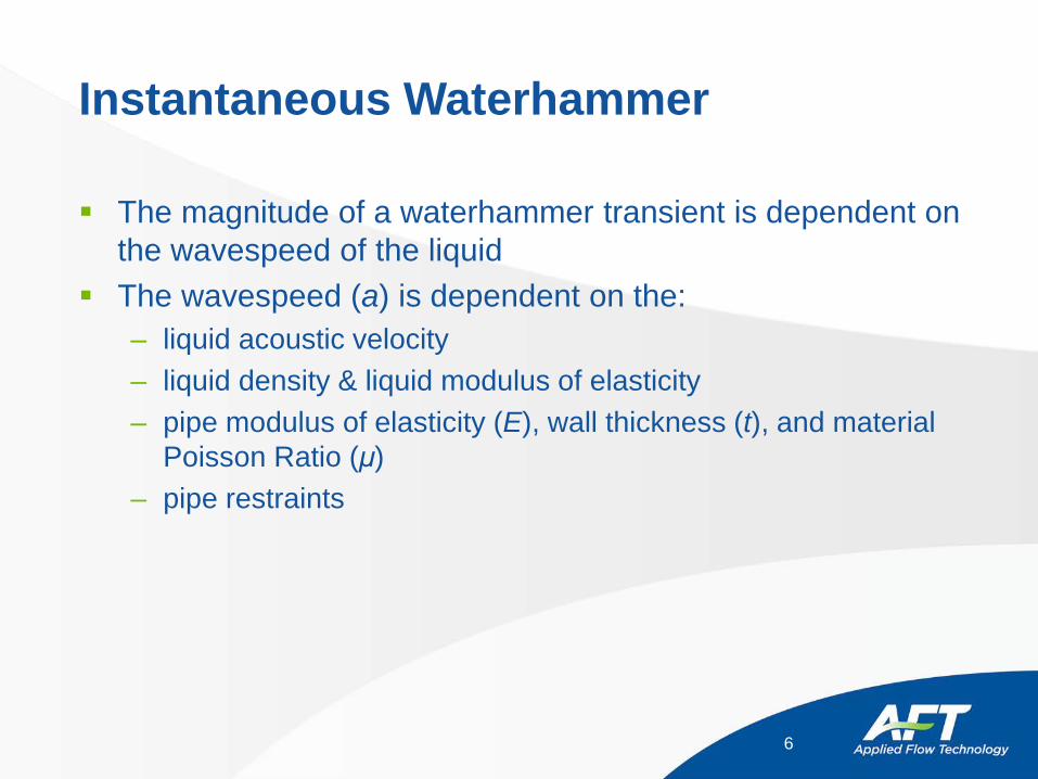
The magnitude of a waterhammer transient is dependent on the wavespeed of the liquid
The wavespeed (a) is dependent on the:– liquid acoustic velocity– liquid density & liquid modulus of elasticity– pipe modulus of elasticity (E), wall thickness (t), and material
Poisson Ratio (μ)– pipe restraints
6
Instantaneous Waterhammer
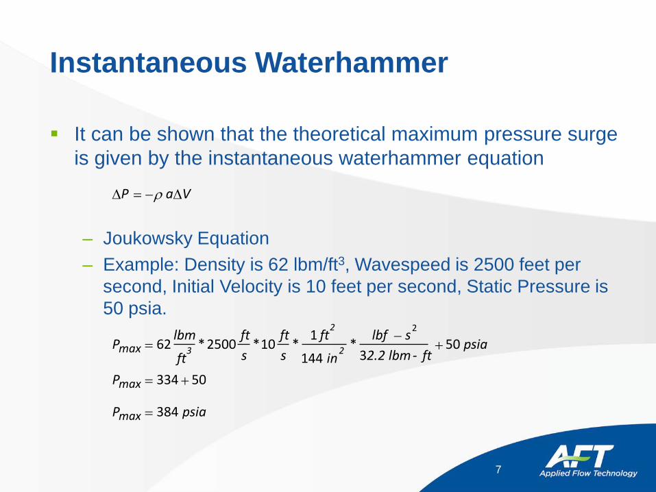
It can be shown that the theoretical maximum pressure surge is given by the instantaneous waterhammer equation
– Joukowsky Equation– Example: Density is 62 lbm/ft3, Wavespeed is 2500 feet per
second, Initial Velocity is 10 feet per second, Static Pressure is 50 psia.
7
∆ ∆P V= −ρ a
P
P
P
max 3
2
2
max
max
lbm
ft
fts
fts
ft
in
lbf s2.2 lbm - ft
psia
psia
=−
+
= +
=
62 2500 101
144 350
334 50
384
2
* * * *
Instantaneous Waterhammer
AFT Impulse assumes constant properties during the simulation– Density– Wavespeed for each pipe
As seen in the Joukowsky equation, a system’s pressure response during fluid transients is directly proportional to the change in velocity
8
Cavitation’s Role in Surge Analysis
If the pressure of the fluid is less than the vapor pressure, a vapor cavity forms– This is sometimes referred to as liquid column separation
When the local pressure increases above the vapor pressure the vapor cavity will begin to shrink– When the cavity completely collapses, a large pressure impulse
is caused Large amounts of cavitation can be extremely problematic for
actual system operation– Cavitation should avoided
9
Two Methods for Handling CavitationDVCM & DGCM Discrete Vapor Cavity Model
– Has been available in AFT Impulse since 1996– Works well for short lived, minor, and localized cavitation– Has the potential to return chaotic/non-real results when
cavitation becomes excessive Discrete Gas Cavity Model
– Has been available in AFT Impulse since 2013– Has the potential to returns more stable results than DVCM,
especially in 2nd, 3rd, etc. pressure spikes.– If cavitation becomes excessive, model has harder time
converging than DVCM– When cavitation is present, this method has the potential to
significantly increase the transient solver run time
10
Limitations of Cavitation Methods
Both DGCM and DVCM are mathematical methods designed to model cavitation under a specific set of assumptions– Localized– Discrete– Subtle
• Usually 10%-15% of pipe section volume
AFT Impulse cavitation models are great for identifying cavitation impact and location, within assumptions
As cavitation volumes become excessive, the validity of results can become uncertain– Large vapor cavities would behave with slug flow or two-phase
flow conditions
11
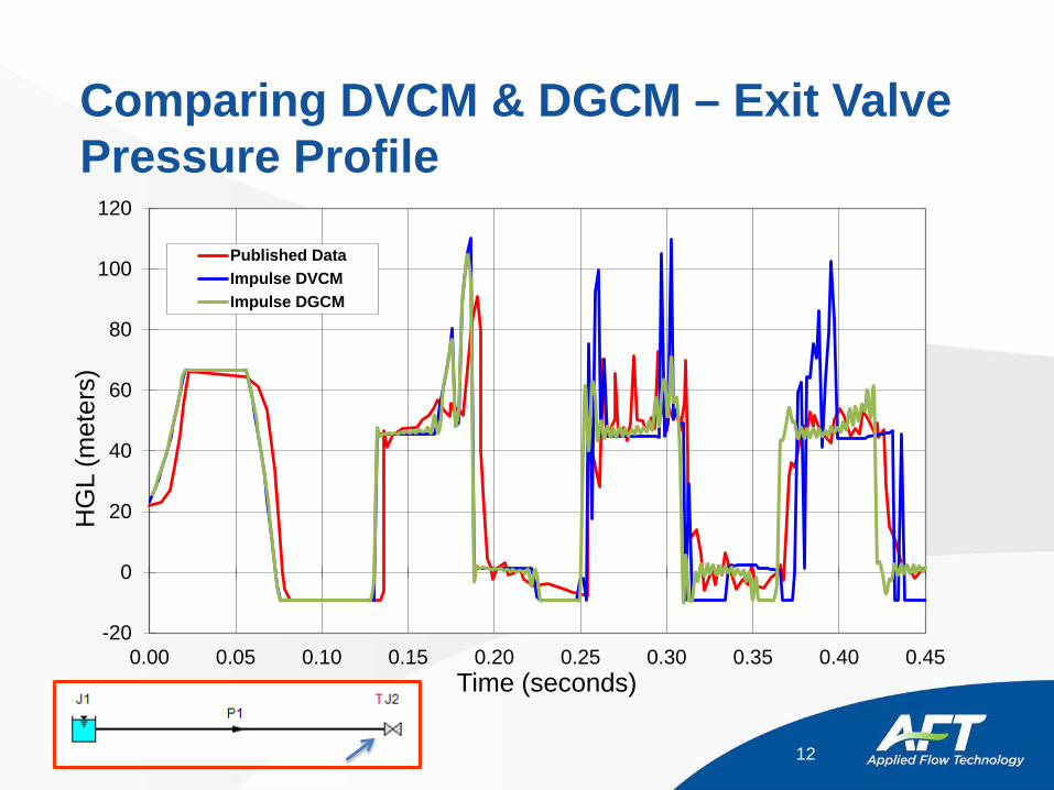
Comparing DVCM & DGCM – Exit Valve Pressure Profile
12
-20
0
20
40
60
80
100
120
0.00 0.05 0.10 0.15 0.20 0.25 0.30 0.35 0.40 0.45
HG
L (m
eter
s)
Time (seconds)
Published DataImpulse DVCMImpulse DGCM
Waterhammer Videos - Cavitation
Instructor – show video files– waterhammer iihr.wmv (1:04)
• Video of rapid, manual valve closure and column separation in a clear line
• online version -http://www.iahrmedialibrary.net/db/i1/waterhammer.htm
– GEFA Water Hammer GB.wmv• High speed movie of a cavitating valve• online version - http://www.youtube.com/watch?v=X9UbzcanuDk
– check valve.wmv (0:44)• Video of check valve• online version – unavailable
13
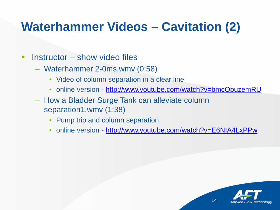
Waterhammer Videos – Cavitation (2)
Instructor – show video files– Waterhammer 2-0ms.wmv (0:58)
• Video of column separation in a clear line• online version - http://www.youtube.com/watch?v=bmcOpuzemRU
– How a Bladder Surge Tank can alleviate column separation1.wmv (1:38)
• Pump trip and column separation • online version - http://www.youtube.com/watch?v=E6NIA4LxPPw
14

Surge Suppression
Surge pressures that are excessively high can burst pipes and damage equipment
Surge pressures that reduce the local pressure can result in:– Crushed pipes
• Due to atmospheric pressure exceeding the internal liquid pressure– Cavitation and liquid column separation
• Can then cause large pressure spikes when the cavity collapses– Sub-atmospheric pressures that are unacceptable for drinking
water pipelines Surge pressures can create imbalanced forces that move
pipes, dislodge insulation and ultimately break supports
15
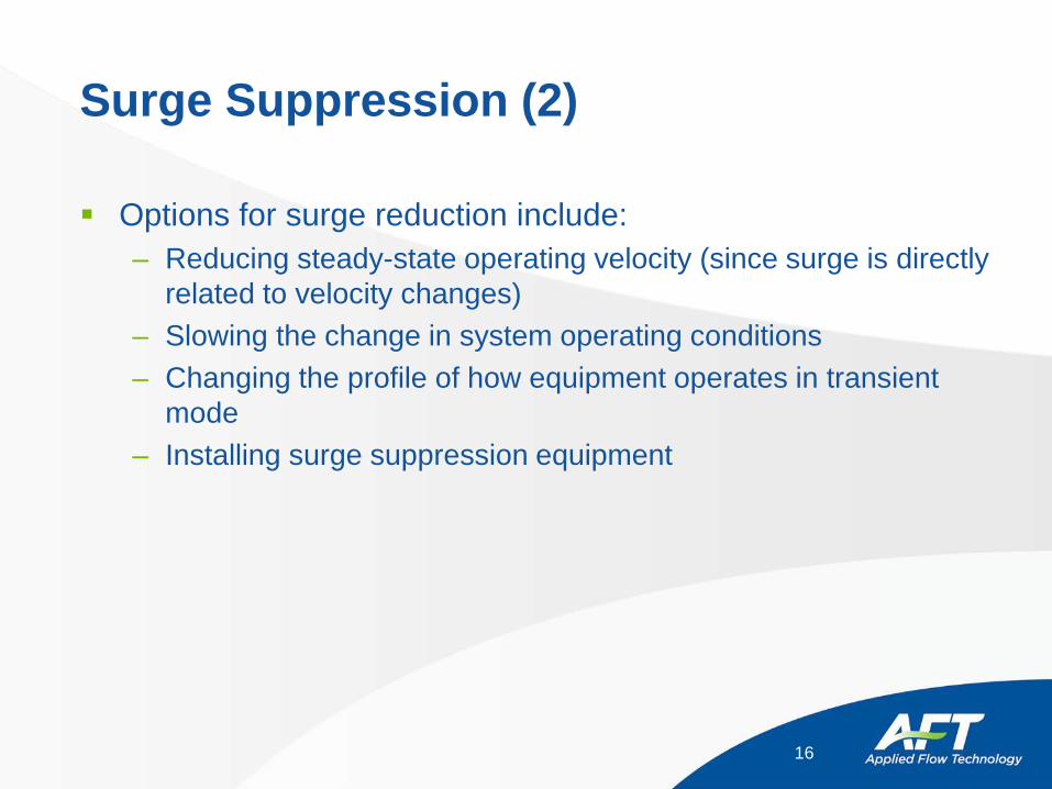
Surge Suppression (2)
Options for surge reduction include:– Reducing steady-state operating velocity (since surge is directly
related to velocity changes)– Slowing the change in system operating conditions– Changing the profile of how equipment operates in transient
mode– Installing surge suppression equipment
16
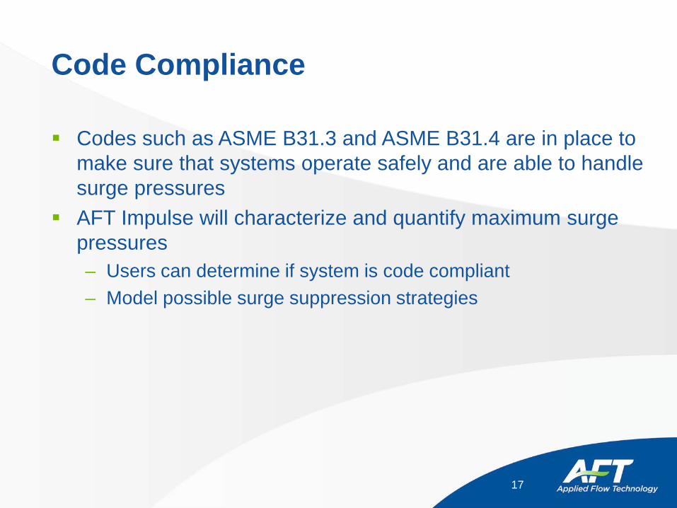
Code Compliance
Codes such as ASME B31.3 and ASME B31.4 are in place to make sure that systems operate safely and are able to handle surge pressures
AFT Impulse will characterize and quantify maximum surge pressures– Users can determine if system is code compliant– Model possible surge suppression strategies
17
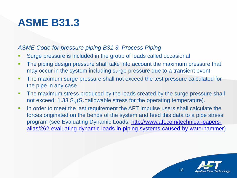
ASME B31.3
ASME Code for pressure piping B31.3. Process Piping Surge pressure is included in the group of loads called occasional The piping design pressure shall take into account the maximum pressure that
may occur in the system including surge pressure due to a transient event The maximum surge pressure shall not exceed the test pressure calculated for
the pipe in any case The maximum stress produced by the loads created by the surge pressure shall
not exceed: 1.33 Sh (Sh=allowable stress for the operating temperature). In order to meet the last requirement the AFT Impulse users shall calculate the
forces originated on the bends of the system and feed this data to a pipe stress program (see Evaluating Dynamic Loads: http://www.aft.com/technical-papers-alias/262-evaluating-dynamic-loads-in-piping-systems-caused-by-waterhammer)
18
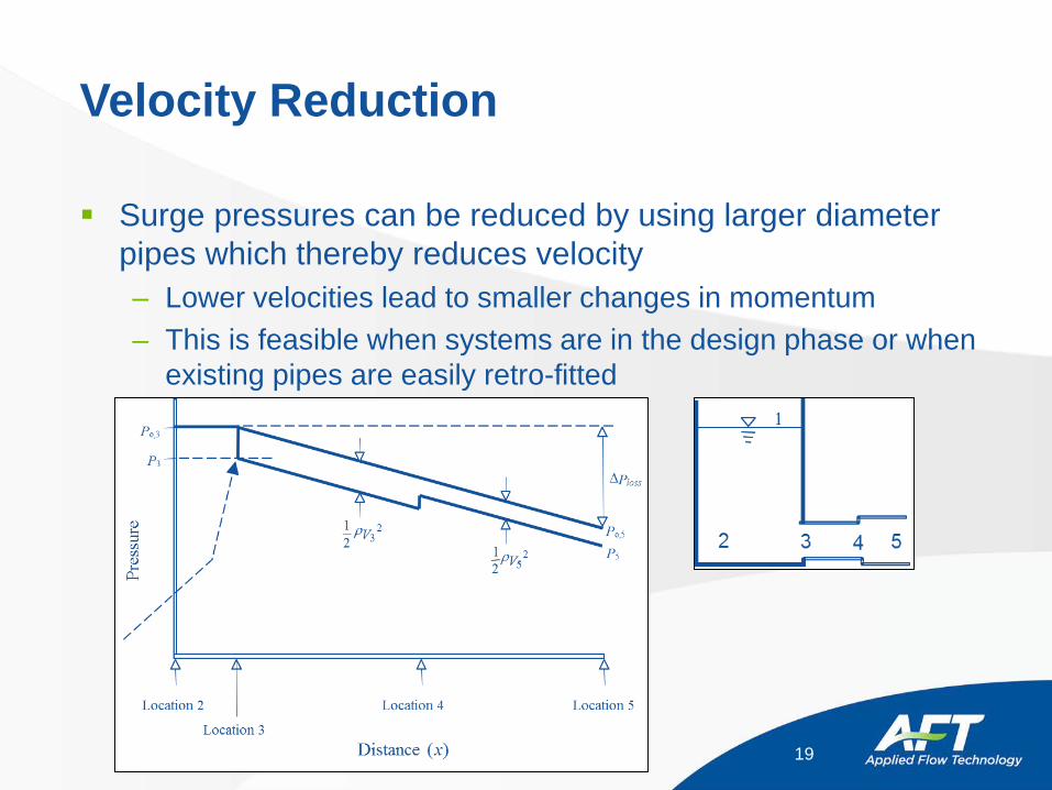
Velocity Reduction
Surge pressures can be reduced by using larger diameter pipes which thereby reduces velocity– Lower velocities lead to smaller changes in momentum– This is feasible when systems are in the design phase or when
existing pipes are easily retro-fitted
19
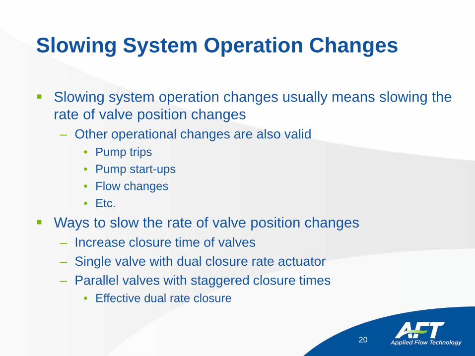
Slowing System Operation Changes
Slowing system operation changes usually means slowing the rate of valve position changes– Other operational changes are also valid
• Pump trips• Pump start-ups• Flow changes• Etc.
Ways to slow the rate of valve position changes– Increase closure time of valves– Single valve with dual closure rate actuator– Parallel valves with staggered closure times
• Effective dual rate closure
20
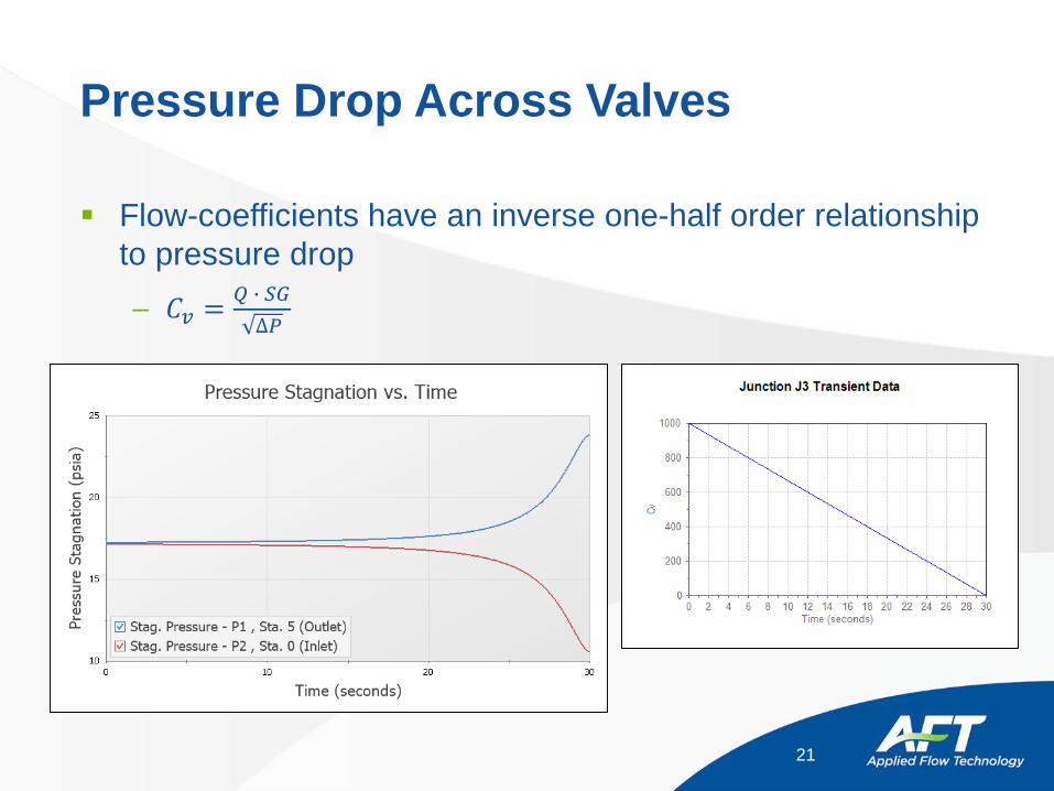
Pressure Drop Across Valves
Flow-coefficients have an inverse one-half order relationship to pressure drop– 𝐶𝐶𝑣𝑣 = 𝑄𝑄 � 𝑆𝑆𝑆𝑆
∆𝑃𝑃
21
Valve Closure Time Increase
For linear closures, sometimes increasing the time needed for the valve to close can lower surge pressures– Surge pressures may still be too high to be code compliant
Operating procedures may prevent increasing time needed to close valve
22
80-20 Rule
Swaffield* discusses how closing valves more quickly at first and then more slowly at the end can result in significant surge reduction– Examples are given where the first 80% of closure occurs over
the first 20% of closure time, with the final 20% closure occurring over the remaining 80% of the time
– Known in other applications as Pareto’s Principle (“80-20 rule”) It should be noted that obtaining accurate transient valve data
can be difficult
23* Swaffield and Boldy, "Pressure Surges in Pipe and Duct Systems"
Multiple Rate Closure Profiles for Single Valves Swaffield’s suggestion can be applied to single valve junctions
– AFT Impulse transient profiles will linearly interpolate between data points
– Valves are not limited to only dual closure rates– As many as able to fit into the transient profile tables
Dual closure rate valve equipment is available on the market Large savings are possible
– Can eliminate the need for additional surge suppression equipment
– The cost of a new motor actuator is inexpensive compared to equipment like surge tanks
24
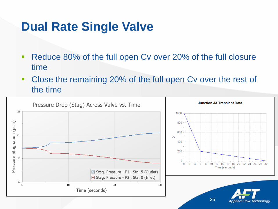
Dual Rate Single Valve
Reduce 80% of the full open Cv over 20% of the full closure time
Close the remaining 20% of the full open Cv over the rest of the time
25
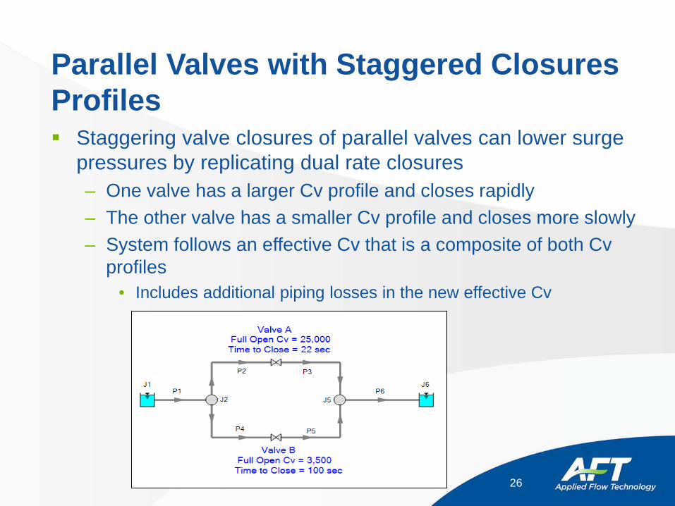
Parallel Valves with Staggered Closures Profiles Staggering valve closures of parallel valves can lower surge
pressures by replicating dual rate closures– One valve has a larger Cv profile and closes rapidly– The other valve has a smaller Cv profile and closes more slowly– System follows an effective Cv that is a composite of both Cv
profiles• Includes additional piping losses in the new effective Cv
26
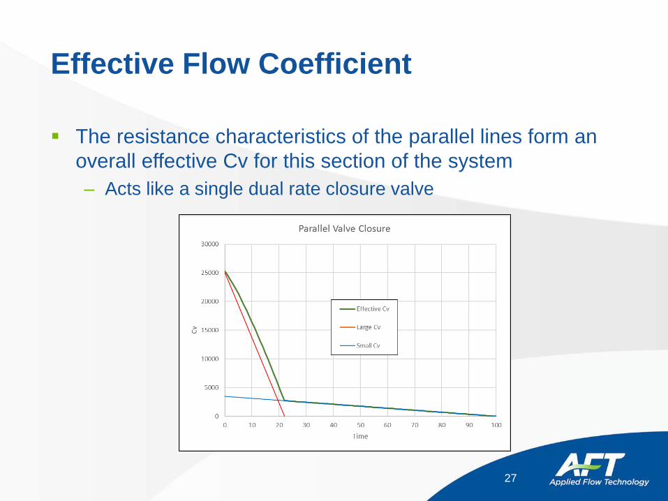
Effective Flow Coefficient
The resistance characteristics of the parallel lines form an overall effective Cv for this section of the system– Acts like a single dual rate closure valve
27
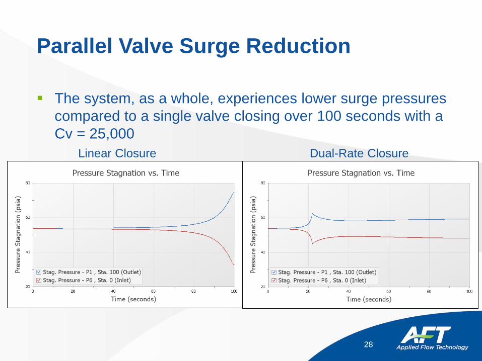
Parallel Valve Surge Reduction
The system, as a whole, experiences lower surge pressures compared to a single valve closing over 100 seconds with a Cv = 25,000
28
Linear Closure Dual-Rate Closure
Notes on Parallel Valve Closures
Economic calculations should be performed regarding the additional piping, valve equipment, and installation expenses– Typically still more cost effective than adding large surge
equipment Experience shows that material costs can be lowered with
existing equipment if present Solution may not be suitable for existing systems
– Difficulty of system expansion
29
Surge Suppression Equipment
Surge suppression equipment is equipment designed specifically for reducing surge pressures
Options for surge suppression equipment depend on steady-state pressure levels and whether one is protecting for high pressure or low
Common choices include:– Gas Accumulators– Surge Tanks– Relief Valves– Vacuum Breaker Valves
30
Waterhammer Videos - Accumulators
Instructor – show video files– How a Bladder Surge Tank can alleviate column
separation2.wmv (1:16)• Gas bladder accumulator upstream of valve which closes• online version - http://www.youtube.com/watch?v=E6NIA4LxPPw
– accumulator after pump trip.wmv (1:23)• Gas bladder accumulator close to pump - after pump trip • online version - http://www.youtube.com/watch?v=kiTzez0x6aQ
31
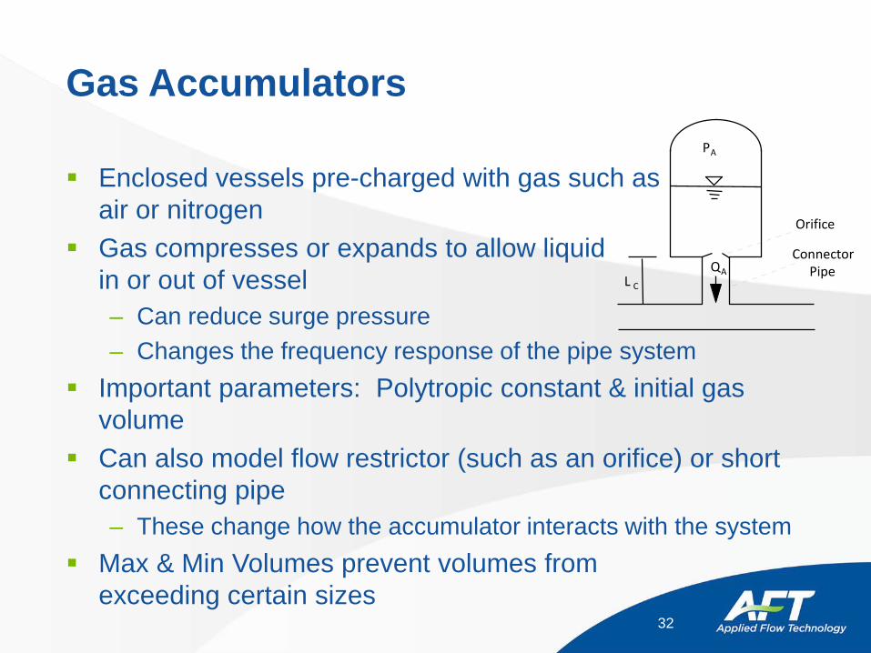
Gas Accumulators
Enclosed vessels pre-charged with gas such as air or nitrogen
Gas compresses or expands to allow liquid in or out of vessel– Can reduce surge pressure– Changes the frequency response of the pipe system
Important parameters: Polytropic constant & initial gas volume
Can also model flow restrictor (such as an orifice) or short connecting pipe– These change how the accumulator interacts with the system
Max & Min Volumes prevent volumes from exceeding certain sizes
32
L C
QA
ConnectorPipe
Orifice
PA
Add Accumulator to Pump Model
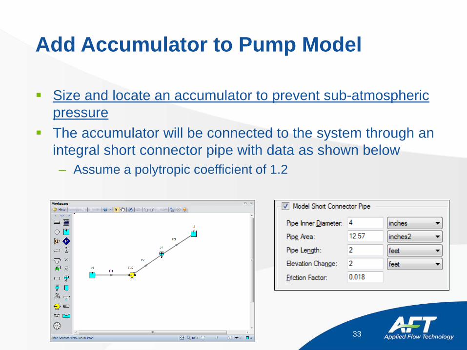
Size and locate an accumulator to prevent sub-atmospheric pressure
The accumulator will be connected to the system through an integral short connector pipe with data as shown below– Assume a polytropic coefficient of 1.2
33
Surge Tanks
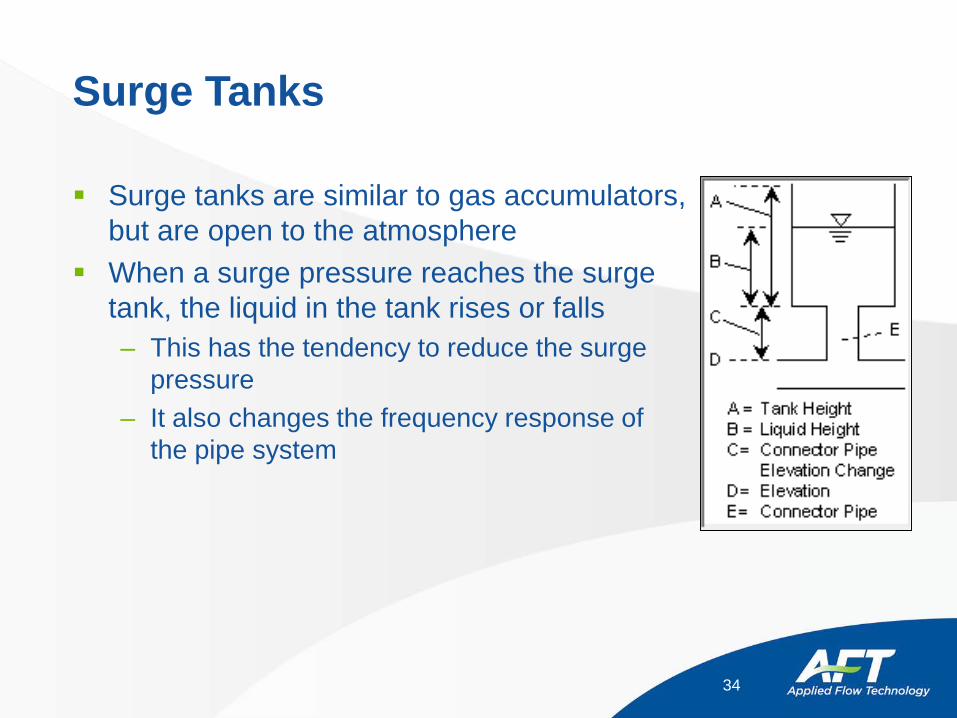
Surge tanks are similar to gas accumulators, but are open to the atmosphere
When a surge pressure reaches the surge tank, the liquid in the tank rises or falls – This has the tendency to reduce the surge
pressure– It also changes the frequency response of
the pipe system
34
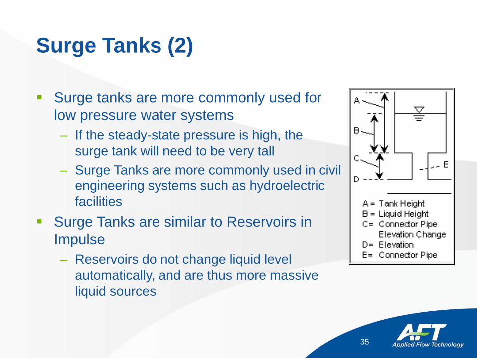
Surge Tanks (2)
Surge tanks are more commonly used for low pressure water systems– If the steady-state pressure is high, the
surge tank will need to be very tall– Surge Tanks are more commonly used in civil
engineering systems such as hydroelectric facilities
Surge Tanks are similar to Reservoirs in Impulse– Reservoirs do not change liquid level
automatically, and are thus more massive liquid sources
35
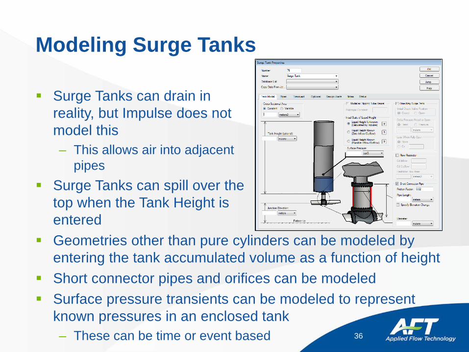
Modeling Surge Tanks
Surge Tanks can drain in reality, but Impulse does not model this– This allows air into adjacent
pipes Surge Tanks can spill over the
top when the Tank Height is entered
Geometries other than pure cylinders can be modeled by entering the tank accumulated volume as a function of height
Short connector pipes and orifices can be modeled Surface pressure transients can be modeled to represent
known pressures in an enclosed tank– These can be time or event based 36
Modeling Surge Tanks (2)
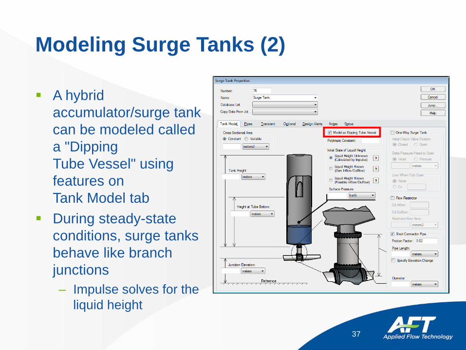
A hybrid accumulator/surge tank can be modeled called a "Dipping Tube Vessel" using features on Tank Model tab
During steady-state conditions, surge tanks behave like branch junctions – Impulse solves for the
liquid height
37

Modeling Surge Tanks (3)
The surge tank can be used as a reference pressure during steady-state– It then acts just like a reservoir junction– The liquid height is input by the user (in the Initial Liquid Height
field)– The surge tank no longer represents a point of mass balance
38
Surge Tank Mitigation
A valve closes while a pump continues to run. The surge caused by the closure is determined to be problematic for the system and needs to be addressed. There is an existing tank at the facility not in use. Economic concerns restrict purchasing any new equipment.
The tank is 15 feet in diameter and 10 feet tall and can be easily fitted to the system 600 feet upstream from the valve.
Surge Pressure may NOT exceed 50 psia. What is the maximum pressure with the tank in place? How
does this compare to not using the tank? Is the tank large enough to prevent overflowing after 20
seconds, long enough for the pump to begin to shutdown?
39

Surge Tank Mitigation (2)
The system is pumping water along a pipeline to a user delivery point.
The tank is to be installed 600 feet upstream of the valve if effective.
40
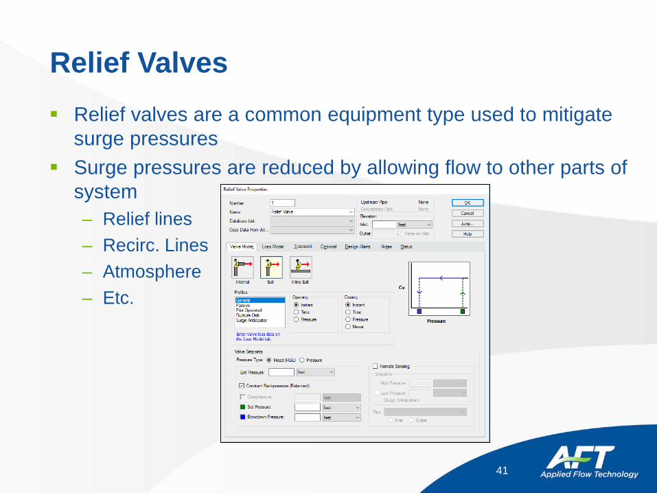
Relief Valves Relief valves are a common equipment type used to mitigate
surge pressures Surge pressures are reduced by allowing flow to other parts of
system– Relief lines– Recirc. Lines– Atmosphere– Etc.
41
Pump Trip Accident
It is recently discovered that during a pump trip, an isolation valve can fail and close faster than expected. A proposed relief valve needs to be validated to ensure the system will still shutdown safely.
Determine the maximum surge pressure in the discharge header using the proposed relief valve installed.
Compare this to the maximum surge pressures without the relief valve.
42
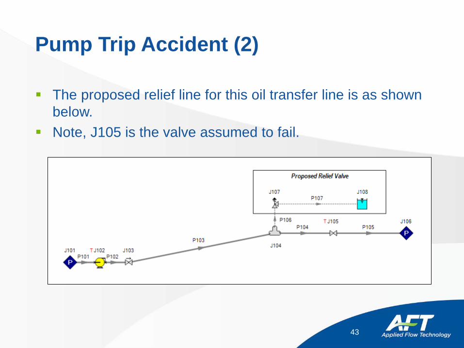
Pump Trip Accident (2)
The proposed relief line for this oil transfer line is as shown below.
Note, J105 is the valve assumed to fail.
43
Vacuum Breaker Valves
Vacuum breaker valves (also known as air valves) are primarily used to protect against low pressure conditions
When the liquid pressure drops below some set pressure (usually atmospheric), air (or any gas you choose) is allowed in to maintain near atmospheric pressure at that location
Vacuum breakers are typically located at high points in the system which are most vulnerable to low pressure transients
44
Vacuum Breaker Valves (2)
Typical designs allow air to flow in and out Five conditions can exist:
– Valve closed • Behaves like a branch junction
– Valve open with subsonic flow in– Valve open with sonic flow in– Valve open with subsonic flow out– Valve open with sonic flow out
45
Modeling Vacuum Breaker Valves
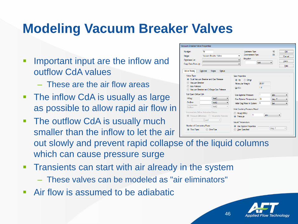
Important input are the inflow and outflow CdA values– These are the air flow areas
The inflow CdA is usually as large as possible to allow rapid air flow in
The outflow CdA is usually much smaller than the inflow to let the air out slowly and prevent rapid collapse of the liquid columns which can cause pressure surge
Transients can start with air already in the system– These valves can be modeled as "air eliminators"
Air flow is assumed to be adiabatic
46
Three Stage Air Release Valves
AFT Impulse allows users to model three stage “Anti-shock” air release and vacuum break valves– This is a particular type of air release valve sold by Vent-O-Mat
valves Three stage valves work the same as regular valves when
gas is flowing in, but they have two orifice sizes when gas flows out
Pressure difference or volumetric flowrate criteria specify which orifice to use– When the actual value is less than the specified value, the
normal Outflow CdA is used– When the actual value is greater than the specified value, the
intermediate orifice CdA is used
47
Three Stage Air Release Valves (2)
Intermediate orifice CdA values are typically much smaller than the normal outflow CdA– This slows the rate of release of the last amounts of gas in the
system, and results in slower fluid velocities as the valve closes– This translates into greatly reduced surge pressures than those
caused by rapidly closing air release valves
48
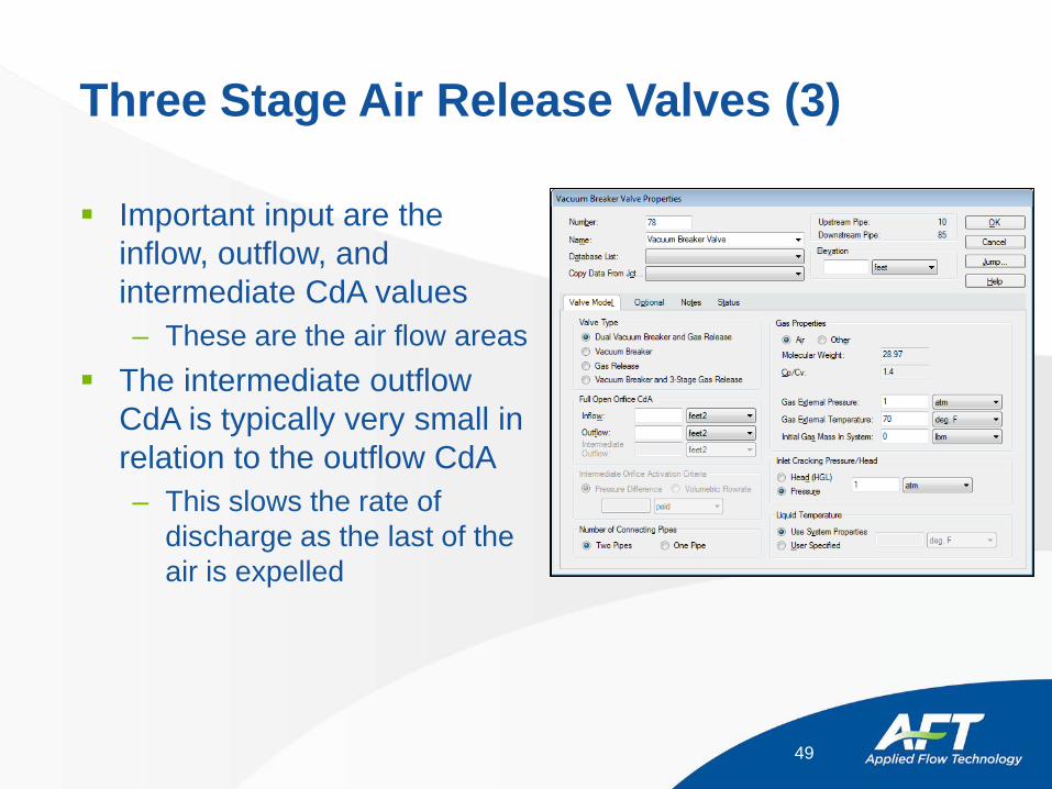
Three Stage Air Release Valves (3)
Important input are the inflow, outflow, and intermediate CdA values– These are the air flow areas
The intermediate outflow CdA is typically very small in relation to the outflow CdA– This slows the rate of
discharge as the last of the air is expelled
49
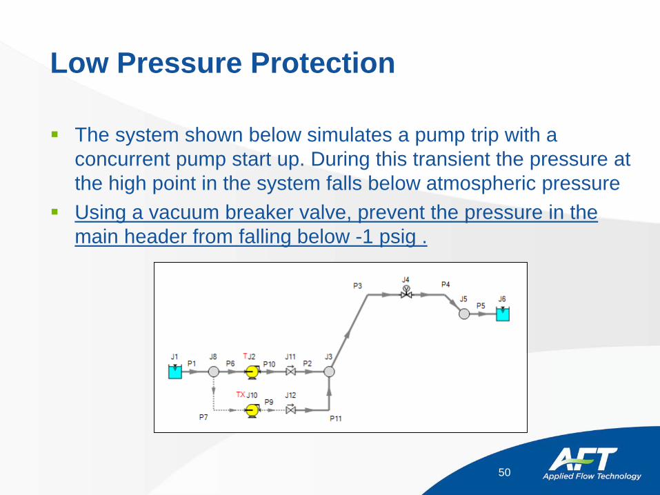
Low Pressure Protection
The system shown below simulates a pump trip with a concurrent pump start up. During this transient the pressure at the high point in the system falls below atmospheric pressure
Using a vacuum breaker valve, prevent the pressure in the main header from falling below -1 psig .
50

Low Pressure Protection (2)
As mentioned previously, large outflow CdA’s for vacuum breaker valves can have adverse affects on piping networks.
Increase the vacuum breaker valve outflow CdA from 0.6 to 6 and compare the pressure response to the original CdA.
What are the maximum and minimum pressures the system will experience in each configuration?
51

Questions?
52