Embed Size (px)
Citation preview
' /i / —7 < •" / 'J / " /
A REVIEW OF
PIPING AND PRESSURE VESSEL CODE
DESIGN CRITERIA
T E C H N I C A L REPORT 217
PREPARED FOR
US ATOMIC ENERGY COMMISSION
CONTRACT NO AT(04-3)-781
BRAUN PROJECT 4122-W
UNITED NUCUEAR PROJECT 2351
C F B R A U N & CO

DISCLAIMER
This report was prepared as an account of work sponsored by an agency of the United States Government. Neither the United States Government nor any agency Thereof, nor any of their employees, makes any warranty, express or implied, or assumes any legal liability or responsibility for the accuracy, completeness, or usefulness of any information, apparatus, product, or process disclosed, or represents that its use would not infringe privately owned rights. Reference herein to any specific commercial product, process, or service by trade name, trademark, manufacturer, or otherwise does not necessarily constitute or imply its endorsement, recommendation, or favoring by the United States Government or any agency thereof. The views and opinions of authors expressed herein do not necessarily state or reflect those of the United States Government or any agency thereof.

DISCLAIMER Portions of this document may be illegible in electronic image products. Images are produced from the best available original document.
C F B R A U N & C O Engineers
A L H A M B H A C A L I F O R N I A 9 1 8 0 2
April 18, 1969
Mr H B Fry Contracting Officer, Contract AT(04-3)-781 AEC San Francisco 2111 Bancroft Way Berkeley, California 94704 BAL-50
Dear Mr Fry REVIEW OF PIPING AND PRESSURE VESSEL CODE DESIGN CRITERIA TECHNICAL REPORT 217 LMFBR PIPING DESIGN GUIDE PROJECT 4122-W
Transmitted herewith are two copies of the final report covering studies of piping and pressure vessel codes.
The purpose of the study was to review the bases used for establishment of design criteria and to evaluate the applicability of these bases and criteria to the more stringent design requirements envisioned for LMFBR piping systems.
Comments on the report from reviewers will be welcome but further revision is not contemplated. The results of the study will be utilized in the preparation of the piping design guide,
Yours very truly
RFD IV <3>^--£>*<-<a*c
Roger Detman Project Manager
L E G A L N O T I C E , This report was prepared as an account of work sponsored by the United States Government. Neither the United States nor the United States Atomic Energy Commission, nor any of their employees, nor any of their contractors, subcontractors, or their employees, makes any warranty, express or implied, or assumes any legal liability or responsibility for the accuracy, com- I pleteness or usefulness of any information, apparatus, product or process disclosed, or represents that its use would not infringe privately owned rights.
BE5TWBUTIOH OP THIS DOCUMENT IS UNUM1TW
C F B R A U N & C 0
Project 4122-W AEC Contract AT(04-3)-781
Mr H B Fry Page 2 April 18, 1969
CC Mr H B Fry, Contracting Officer -2 Director, RDT, HQ Asst. Director, Project Management, RDT, HQ Asst. Director, Plant Engineering, RDT, HQ Asst. Director, Engineering Standards, RDT, HQ Asst. Director, Reactor Engineering, RDT, HQ Asst. Director, Reactor Technology, RDT, HQ Chief, Liquid Metal Projects Br., RDT, HQ Project Manager, LMEC, RDT, HQ -2 Program Manager, LMFBR, RDT, HQ Chief, Facilities Br., RDT, HQ Chief, Components Br., RDT, HQ Chief, Instrumentation and Control Br., RDT, HQ Chief, L.M. Systems Br., RDT, HQ Manager, SAN Director, LMFBR Prograitf Office (ANL) RDT Senior Site Representative (AI) -2 Director, LMEC -\y Contract Representative, CP-AEC
CFB-4122-217
A REVIEW OF
PIPING AND PRESSURE VESSEL CODE
DESIGN CRITERIA
TECHNICAL REPORT 217
L E G A L N O T I C E -This report was prepared as an account of work sponsored by the United States Government. Neither the United States nor the United States Atomic Energy Commission, nor any of their employees, nor any of their contractors, subcontractors, or their employees, makes any warranty, express or implied, or assumes any legal liability or responsibility for the accuracy, completeness or usefulness of any information, apparatus, product or process disclosed, or represents that its use would not infringe privately owned rights.
P r e p a r e d for US Atomic Energy Commission
Contract No AT (04-3) -781
Braun Projec t 4122-W
United Nuclear Pro jec t 2351
C F B R A U N & CO
Alhambra California
April 18, 1969
•KTRIBUTIOK OF THIS DOCUMENT IS ON "Tj
T h i s T e c h n i c a l and c r i t e r i a of USASI Code f o r s i n c e t h e i r i n c Recommendations t h e s p e c i a l nee<
PREFACE
R e p o r t s u m m a r i z e s a r e v i e w o f t h e d t h e ASME B o i l e r a n d P r e s s u r e V e s s e
P r e s s u r e P i p i n g . I t t r a c e s t h e h i s s p t i o n a n d c r i t i c a l l y r e v i e w s t h e i r
a r e made c o n c e r n i n g t h e a p p l i c a b i l 3s o f LMFBR l i q u i d s o d i u m p i p i n g .
e s i g n p h i l o s o p h i e s 1 Code and t h e t o r y of t h e s e Codes
p r e s e n t s t a t u s , i t y of t h e Codes t o
The r e p o r t i s one of a s e r i e s d e s i g n e d t o p r e s e n t t h e f i n d i n g s of s t u d i e s made by t h e a u t h o r s i n t h e deve lopmen t and v e r i f i c a t i o n of a P i p i n g Des ign Guide f o r LMFBR sodium p i p i n g s y s t e m s f o r t h e US Atomic Energy Commission. The f o l l o w i n g s t u d i e s have so f a r been i d e n t i f i e d u n d e r t h i s t a s k .
TECHNICAL REPORT NO
100
110
210
214
217
220
223
2 2 8
2 3 1
234
237
240
243
TITLE
The D e v e l o p m e n t a n d V e r i f i c a t i o n o f a D e s i g n G u i d e f o r LMFBR S o d i u m P i p i n g
LMFBR S y s t e m R e q u i r e m e n t s
A S t u d y o f F a i l u r e T h e o r i e s a s R e l a t e d t o LMFBR P i p i n g S y s t e m s
A R e v i e w o f P i p i n g F a i l u r e E x p e r i e n c e
A R e v i e w o f P i p i n g a n d P r e s s u r e V e s s e l Code D e s i g n C r i t e r i a
A R e v i e w o f F a b r i c a t i o n a n d I n s t a l l a t i o n R e q u i r e m e n t s f o r LMFBR P i p i n g
A S t u d y o f H e a t i n g a n d I n s u l a t i o n M e t h o d s f o r LMFBR S o d i u m P i p i n g
A R e v i e w o f LMFBR P i p i n g M a t e r i a l s
A S t u d y o f LMFBR S y s t e m I n t e r f a c e s
A S t u d y o f S c a l e Mode l T e s t i n g M e t h o d s A p p l i c a b l e t o LMFBR P i p i n g D e s i g n
A S t u d y o f Dynamic A n a l y s i s M e t h o d s a s R e l a t e d t o LMFBR P i p i n g S y s t e m s
A S t u d y o f I n s t a b i l i t y A n a l y s i s M e t h o d s a s R e l a t e d t o LMFBR P i p i n g S y s t e m s
A R e v i e w o f I n - s e r v i c e S u r v e i l l a n c e M e t h o d s A p p l i c a b l e t o L i q u i d S o d i u m P i p i n g
ISSUE DATE
1 - 2 4 - 6 9
1 0 - 2 5 - 6 8
1 - 3 1 - 6 9
3 - 2 8 - 6 9 ( F ) *
4 - 1 8 - 6 9 ( F ) *
2 - 2 8 - 6 9
2 - 2 8 - 6 9
4 - 3 - 6 9
3 - 2 8 - 6 9
( A p r i l 1 9 6 9 )
1 2 - 2 0 - 6 8
2 - 1 3 - 6 9
( A p r i l 1 9 6 9 )
* ( F ) D a t e o f f i n a l i s s u e . A l l o t h e r s a r e f o r p r e l i m i n a r y i s s u e .
C F B r a u n & Co
A l h a m b r a , C a l i f o r n i a
C F B R A U N & C O
1
A REVIEW OF PIPING AND PRESSURE VESSEL CODE
DESIGN CRITERIA
TECHNICAL REPORT 217
CONTENTS
PAGE
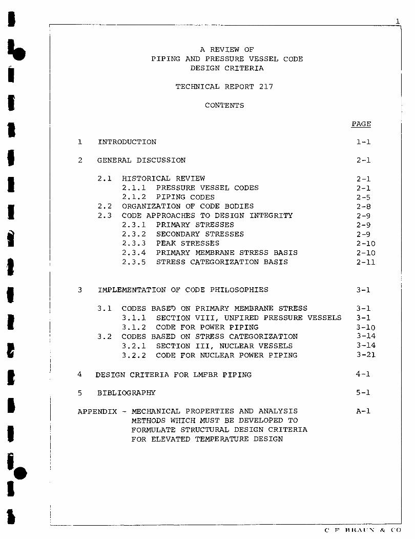
1 INTRODUCTION
2 GENERAL DISCUSSION
2.1 HISTORICAL REVIEW
2.1.1 PRESSURE VESSEL CODES 2.1.2 PIPING CODES
2.2 ORGANIZATION OF CODE BODIES 2.3 CODE APPROACHES TO DESIGN INTEGRITY
2.3.1 PRIMARY STRESSES 2.3.2 SECONDARY STRESSES 2.3.3 PEAK STRESSES 2.3.4 PRIMARY MEMBRANE STRESS BASIS 2.3.5 STRESS CATEGORIZATION BASIS
1-
2-
2-2-2-2-2-2-2-2-2-2-
-1
-1
-1 -1 -5 -8 -9 -9 -9 -10 -10 -11
IMPLEMENTATION OF CODE PHILOSOPHIES 3-1
3.1 CODES BASED ON PRIMARY MEMBRANE STRESS 3-1 3.1.1 SECTION VIII, UNFIRED PRESSURE VESSELS 3-1 3.1.2 CODE FOR POWER PIPING 3-10
3.2 CODES BASED ON STRESS CATEGORIZATION 3-14 3.2.1 SECTION III, NUCLEAR VESSELS 3-14 3.2.2 CODE FOR NUCLEAR POWER PIPING 3-21
4 DESIGN CRITERIA FOR LMFBR PIPING
5 BIBLIOGRAPHY
APPENDIX - MECHANICAL PROPERTIES AND ANALYSIS METHODS WHICH MUST BE DEVELOPED TO FORMULATE STRUCTURAL DESIGN CRITERIA FOR ELEVATED TEMPERATURE DESIGN
4-1
5-1
A-l
C F BRAIN & CO

1-1
1 INTRODUCTION
C F Braun & Co has been awarded a contract ' by the US Atomic Energy Commission for the development and verification of a Piping Design Guide for sodium-cooled fast breeder reactor power plants (LMFBR). The work is a Priority 1 Task under the LMFBR Program Plan(2) prepared for the USAEC Division of Reactor Development and Technology (RDT) by the LMFBR Program Office, Argonne National Laboratory. It is identified in the Program Plan as Task 3-8.2, Development of Design Technology for Piping. Technical Report 100, already issued under this contract, gives a detailed description of the work plan for the project.
This Technical Report presents a review of existing and past US Codes for the design of pressure vessels and piping. Tracing their development since their inception, their philosophy, criteria and design rules are compared objectively to establish their present rationale. An evaluation is then made to determine their applicability to the special environment of the LMFBR.
A review procedure has been established to ensure consistency between interdependent studies currently being performed under this and other task areas of the LMFBR Program Plan. Under the review procedure, the Liquid Metal Engineering Center, (LMEC), is the coordinating agency. Technical Reports prepared by Braun under this contract are distributed by LMEC to appropriate Review Agencies designated by USAEC.
This report, issued in preliminary draft form on December 13, 1968, has been reviewed under the procedure described above. Pertinent comments received from Review Agencies have been incorporated, and the report has been released by USAEC for final publication. Except for a number of relatively minor changes and corrections of an editorial nature, only Section 4 has been changed significantly.
(1) AT(04-3)-781, AEC San Francisco Operation Office (SAN) (2) Liquid Metal Fast Breeder Reactor Program Plan, LMFBR Program
Office, Argonne National Laboratory - AEC R&D Report, Reactor Technology, WASH-1101, August 1968
PV C F BRAUN & CO

2-1
2 GENERAL DISCUSSION
2.1 HISTORICAL REVIEW
It is perhaps not surprising that the Codes which have been developed to regulate and unify the design of both pressure vessels and piping have followed closely parallel paths. Both relate to the pressure-containing parts of systems comprising interconnected vessels and piping subjected to similar environmental conditions; materials of construction and fabrication methods are similar; and both have many design features in common - eg, flanges, openings, etc.
Also contributing to their similarity is the composition of the various Committees under which both regulatory bodies operate; many companies and organizations are represented on both pressure vessel and piping Committees, sometimes by the same individual, leading naturally to a continuity and uniformity of approach which has done much to make each complementary to the other.
Despite the factors instrumental in achieving their parallel development, the Codes have nevertheless remained separate entities and have had very different origins. In reviewing their histories it will be appropriate to deal with each separately.
2.1.1 PRESSURE VESSEL CODES (1,2)* It has been over a hundred years since the worst boiler-explosion disaster ever recorded first emphasized the need for legislative measures to regulate the design and operation of steam-raising equipment. On April 27, 1865, the boiler of the Mississippi steamboat Sultana exploded seven miles north of Memphis with 2,021 persons aboard, resulting in the total destruction of the vessel and the appalling loss of 1,450 lives, mostly Union prisoners just released from Southern prison camps at Vicksburg. One report set the death toll even higher, at 1,500.
Although the Commonwealth of Massachusetts had presaged this event by passing "An Act to Prevent the Explosion of Steam Boilers" in 1849, thus becoming the first state to enact legislation along these lines, the terms of the Act were quite inadequate and did little more than require the provision of a fusible plug on all steam engines and boilers. These rules were amended in 1880 to allow for periodic inspection of the outside of boilers, and for the licensing of engineers and firemen.
In 1894 another spectacular explosion occurred in which 27 boilers out of a battery of 36 at a coal mine near Shamokin, Pennsylvania, burst in rapid succession, totally destroying the entire facility at the cost of 6 lives and millions of dollars in property damage.
•References are listed numerically in Section 6, Bibliography
P\7 C F B R A U N & CO

2-2
2.1.1 PRESSURE VESSEL CODES (Continued)
Boiler failures continued to occur with unremitting frequency. In the ten-year period 1895-1904, no fewer than 3,612 boiler explosions were officially recorded - an average of one a day. Loss of life ran at twice this rate, for a total of over 7,600. And these figures do not include an uncountable number of minor failures and mishaps.
Ironically it was in Massachusetts, still the only state with safety regulations of any consequence, that two more catastrophic boiler explosions were to be recorded. At Brockton on March 20, 1905, the R B Grover Shoe Company plant was destroyed, killing 58 persons and injuring 117, causing $250,000 property loss with an additional $280,000 in subsequent litigation. And barely a year later, at Lynn, a half million dollar loss ensued from a night-time factory explosion in which, miraculously, only 3 were injured. Immediate public reaction resulted in the establishment, in August 1907, of a Board of Boiler Rules in Massachusetts, the first effective legislation of its kind in the United States.
It was not long before other states followed the lead set by the Bay State, frequently precipitated into action as a consequence of further boiler disasters: New York and Ohio did so in 1911; New Jersey, 1913; Indiana, 1915; Pennsylvania, 1916; California, Michigan and Arkansas, 1917; Delaware and Oklahoma, 1918; and Oregon in 1920.
The natural outcome of this flurry of legislation was a situation approaching chaos. No two states had the same rules: materials and procedures considered safe in one state were prohibited in another; no manufacturer could afford the risk of building stocks of packaged units since he could never be sure they would prove acceptable to out-of-state purchasers; owners could seldom move boiler units from a plant in one state to one in another; and serious difficulties arose in validating the inspection of boilers destined for out-of-state use.
Meanwhile, the American Society of Mechanical Engineers, already recognized as the foremost engineering organization in the United States, was being urged by an interested section of its membership to formulate and recommend uniform standard specifications for the design, construction and operation of steam boilers and other pressure vessels. Responding to this pressure, in 1911 the Council of ASME accordingly appointed a Committee of seven outstanding engineers to study the problem. In 1914 an Advisory Committee of 18 was appointed to handle matters of detail, and later in the same year the two bodies were merged under the name of the Boiler Code Committee. On February 15, 1915, the final draft of Section I, Power Boilers, of the first ASME Boiler Code was submitted to the Council of ASME for approval.
PV C F BRAUN &. CO
2-3
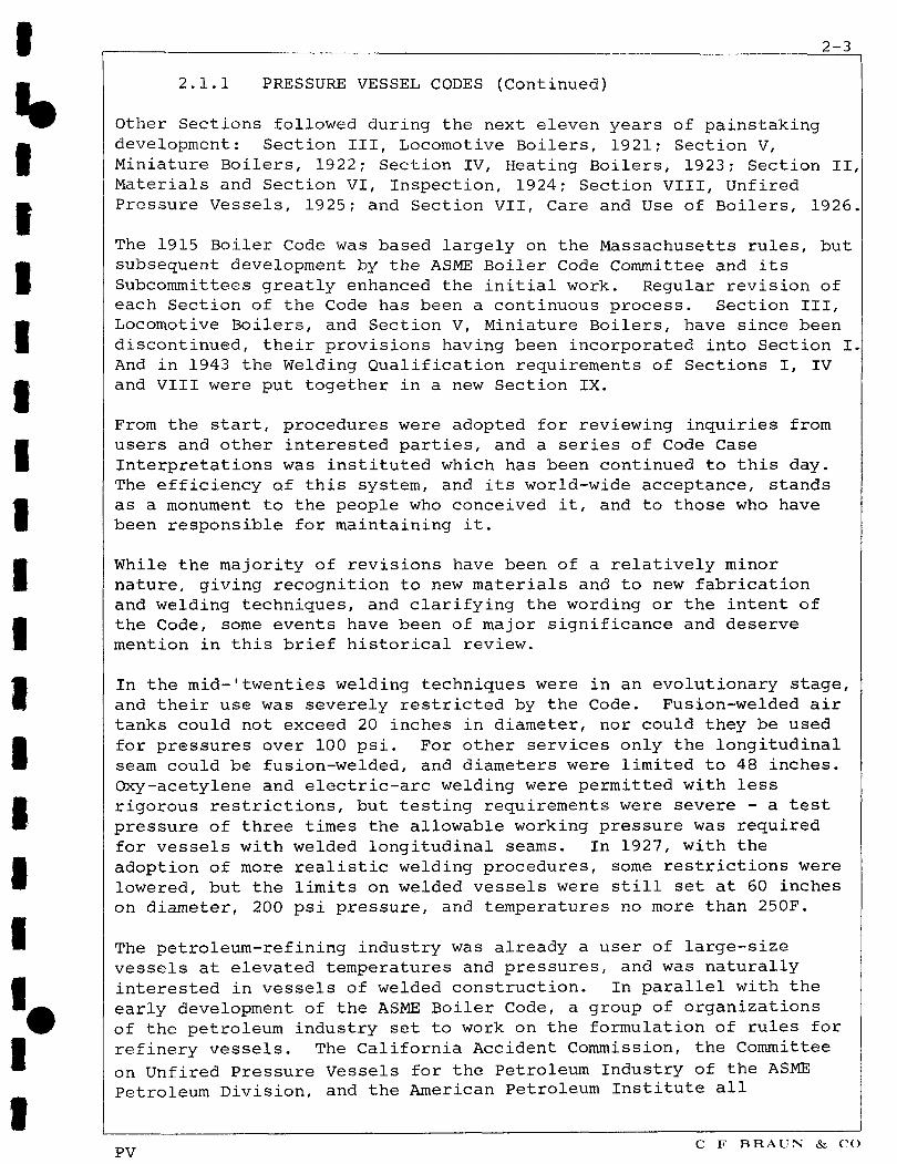
2.1.1 PRESSURE VESSEL CODES (Continued)
Other Sections followed during the next eleven years of painstaking development: Section III, Locomotive Boilers, 1921; Section V, Miniature Boilers, 1922; Section IV, Heating Boilers, 1923; Section II, Materials and Section VI, Inspection, 1924; Section VIII, Unfired Pressure Vessels, 1925; and Section VII, Care and Use of Boilers, 1926.
The 1915 Boiler Code was based largely on the Massachusetts rules, but subsequent development by the ASME Boiler Code Committee and its Subcommittees greatly enhanced the initial work. Regular revision of each Section of the Code has been a continuous process. Section III, Locomotive Boilers, and Section V, Miniature Boilers, have since been discontinued, their provisions having been incorporated into Section I. And in 1943 the Welding Qualification requirements of Sections I, IV and VIII were put together in a new Section IX.
From the start, procedures were adopted for reviewing inquiries from users and other interested parties, and a series of Code Case Interpretations was instituted which has been continued to this day. The efficiency of this system, and its world-wide acceptance, stands as a monument to the people who conceived it, and to those who have been responsible for maintaining it.
While the majority of revisions have been of a relatively minor nature, giving recognition to new materials and to new fabrication and welding techniques, and clarifying the wording or the intent of the Code, some events have been of major significance and deserve mention in this brief historical review.
In the mid-'twenties welding techniques were in an evolutionary stage, and their use was severely restricted by the Code. Fusion-welded air tanks could not exceed 20 inches in diameter, nor could they be used for pressures over 100 psi. For other services only the longitudinal seam could be fusion-welded, and diameters were limited to 48 inches. Oxy-acetylene and electric-arc welding were permitted with less rigorous restrictions, but testing requirements were severe - a test pressure of three times the allowable working pressure was required for vessels with welded longitudinal seams. In 1927, with the adoption of more realistic welding procedures, some restrictions were lowered, but the limits on welded vessels were still set at 60 inches on diameter, 200 psi pressure, and temperatures no more than 250F.
The petroleum-refining industry was already a user of large-size vessels at elevated temperatures and pressures, and was naturally interested in vessels of welded construction. In parallel with the early development of the ASME Boiler Code, a group of organizations of the petroleum industry set to work on the formulation of rules for refinery vessels. The California Accident Commission, the Committee on Unfired Pressure Vessels for the Petroleum Industry of the ASME Petroleum Division, and the American Petroleum Institute all
PV C F BRAUN & CO

2-4
2.1.1 PRESSURE VESSEL CODES (Continued)
contributed to the work, and in 1931 the API and ASME met together to discuss their common objectives. The outcome was a joint API-ASME Code designed specifically for the petroleum industry. It made its first appearance in September 19 34, followed by a second, more complete, edition in 1936.
There were several important differences between the API-ASME Code and Section VIII of the ASME Boiler Code. On the whole the API-ASME Code was the less conservative, being based on a safety factor of 4 instead of 5. Joint efficiency factors were higher and stress-relief was required only for plate thicknesses over 1.25 inches. On the other hand, many of the rules for detail design were more demanding in the API-ASME Code. These differences were an embarrassment to both users and fabricators, and in 1935 the ASME Boiler Code Committee appointed a Special Committee to Revise Section VIII under the chairmanship of Dr E 0 Bergman, comprising three members from API, three from ASME, a member of the National Board of Boiler and Pressure Vessel Inspectors, and a representative from the vessel fabrication industry. Their task was to seek agreement on terms for a single Code for all services.
After fourteen years of deliberation, during which time five drafts were prepared and dozens of controversial matters had been disposed of, a final draft was approved by the ASME Council on August 9, 1949. However, as now approved, Section VIII still did not agree with the API-ASME Code in every respect, and further revisions were made in 1950 and 1952. Finally, on December 31, 1956, the API-ASME Code was formally abandoned in favor of Section VIII of the ASME Boiler and Pressure Vessel Code (3).
Another development, and one which has special significance to this present study, has been the formulation of a new Section III for Nuclear Pressure Vessels. Early in 1955 the ASME Boiler and Pressure Vessel Committee organized the Special Committee to Review Code Stress Basis. It was created primarily to make recommendations to the Main Committee as to what should constitute logical criteria for establishing maximum allowable stress values for both ferrous and nonferrous materials. In carrying out its assignment the Special Committee was instructed to,
1) Review and evaluate the basis of the existing Code maximum allowable stresses for ferrous and nonferrous materials
2) Review and evaluate the Pressure Vessel Research Committee's, and related, experimental and analytical investigations of the influence of materials, design, and other factors on the performance of pressure vessels
PV C F BRAUN & CO
2-5
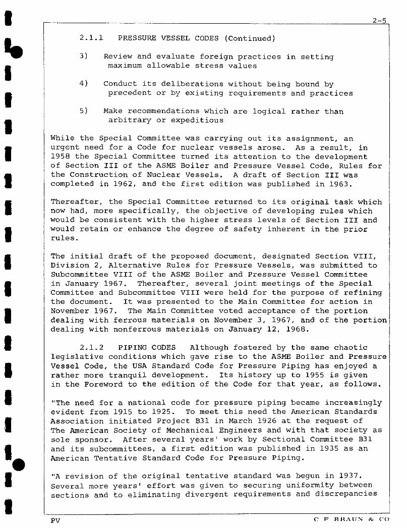
2.1.1 PRESSURE VESSEL CODES (Continued)
3) Review and evaluate foreign practices in setting maximum allowable stress values
4) Conduct its deliberations without being bound by precedent or by existing requirements and practices
5) Make recommendations which are logical rather than arbitrary or expeditious
While the Special Committee was carrying out its assignment, an urgent need for a Code for nuclear vessels arose. As a result, in 1958 the Special Committee turned its attention to the development of Section III of the ASME Boiler and Pressure Vessel Code, Rules for the Construction of Nuclear Vessels. A draft of Section III was completed in 1962, and the first edition was published in 1963.
Thereafter, the Special Committee returned to its original task which now had, more specifically, the objective of developing rules which would be consistent with the higher stress levels of Section III and would retain or enhance the degree of safety inherent in the prior rules.
The initial draft of the proposed document, designated Section VIII, Division 2, Alternative Rules for Pressure Vessels, was submitted to Subcommittee VIII of the ASME Boiler and Pressure Vessel Committee in January 1967. Thereafter, several joint meetings of the Special Committee and Subcommittee VIII were held for the purpose of refining the document. It was presented to the Main Committee for action in November 1967. The Main Committee voted acceptance of the portion dealing with ferrous materials on November 3, 1967, and of the portion dealing with nonferrous materials on January 12, 1968.
2.1.2 PIPING CODES Although fostered by the same chaotic legislative conditions which gave rise to the ASME Boiler and Pressure Vessel Code, the USA Standard Code for Pressure Piping has enjoyed a rather more tranquil development. Its history up to 1955 is given in the Foreword to the edition of the Code for that year, as follows.
"The need for a national code for pressure piping became increasingly evident from 1915 to 1925. To meet this need the American Standards Association initiated Project B31 in March 1926 at the request of The American Society of Mechanical Engineers and with that society as sole sponsor. After several years' work by Sectional Committee B31 and its subcommittees, a first edition was published in 1935 as an American Tentative Standard Code for Pressure Piping.
"A revision of the original tentative standard was begun in 1937. Several more years' effort was given to securing uniformity between sections and to eliminating divergent requirements and discrepancies
PV C F B R A U N & CO
2-6
2.1.2 PIPING CODES (Continued)
as well as to keeping the code abreast of current developments in welding technique, stress computations, and reference to new dimensional and materials standards. During this period a new section was added on refrigeration piping, prepared in cooperation with the American Society of Refrigeration Engineers and complementing the American Standard Code for Mechanical Refrigeration. This work culminated in the 1942 American Standard Code for Pressure Piping.
"Supplements 1 and 2 of the 1942 code which appeared in 1944 and 1947 respectively, introduced new dimensional and materials standards, a new formula for pipe wall thickness, and more comprehensive requirements for instrument and control piping. Shortly after the 1942 code was issued, procedures were established for handling inquiries that require explanation or interpretation of code requirements, and for publishing such inquiries and answers in Mechanical Engineering for the information of all concerned.
"Continued increases in the severity of service conditions, with concurrent developments of new materials and designs equal to meeting these higher requirements, had pointed the need by 1948 for more extensive changes in the code than could be provided by supplements alone. By that time also the then existing personnel of Sectional Committee B31 was in need of reorganization to fill vacancies and to replace with new blood those members whose interests had changed over the years. During the first 20 years of its existence, the sectional committee retained much of the same personnel and operated with a definite continuity. By 1948, however, it became apparent that the old membership had in part disappeared or was out of touch with developments in this field. The decision was therefore reached by the American Standards Association and the sponsor to reorganize the sectional committee and its several subcommittees, and to invite the various interested bodies to reaffirm their representatives or to designate new ones.
"Because of the wide field involved, some 30 to 40 different engineering societies, government bureaus, trade associations, institutes and the like have one or more representatives on the sectional committee plus a few "members at large" to represent general interests. In addition to active voting members on subcommittees, there are several "corresponding members" who receive mailings and who are urged to comment if they so desire. Code activities are subdivided according to the scope of the several sections and chapters listed in the Table of Contents...General direction of code activities rests with the sectional committee officers and an executive committee whose membership consists principally of sectional committee officers and section chairmen. There also is a subcommittee on Coordination (editing and interpretations) and another on Liaison with Other Codes and Standards
PV C F BRAUN & CO

2-7
2.1.2 PIPING CODES (Continued)
"The reorganized Sectional Committee B31 made an extensive review of the 1942 code which resulted in: (1) A general revision and extension of requirements to agree with present day practice; (2) the revision of references of existing dimensional standards and material specifications and the addition of references to new ones; and (3) the clarification of ambiguous or conflicting requirements. A revision was prepared which was finally approved as American Standard in February, 1951, with the designation B31.1-1951.
"Following the publication of the 1951 code, the committee that had been working jointly with the ASME Boiler Code Committee and ASA Sectional Committees B16 and B36 recommended a revised basis for establishing allowable stresses for certain materials common to the several codes and standards. Sectional Committee B31 approved this new basis for establishing allowable stresses and in order to make the revisions available to code users, issued Supplement 1 to the Code B31.1-1953 which had received American Standards Association approval April 30, 1953.
"At its meeting November 29, 1951, Sectional Committee B31 authorized separating Section 2 on Gas and Air Piping Systems into two sections - Section 2 on Gas and Air Piping for Industrial Installations, and Section 8 on Gas Transmission and Distribution Piping Systems. The latter section was to incorporate the applicable parts of Section 6 Fabrication Details, and Section 7 Materials - Their Specifications and Identification. The purpose was to provide an integrated document for Gas Transmission and Distribution Piping which would not require cross-referencing to other sections of the code. Upon completion it was approved by the American Standards Association September 29, 1952, with the designation B31.1.8-1952. Section 2 was rewritten in the light of its new scope and became a part of (the) 1955 revision.
"Developments indicated the need for further work on Section 8 so the committee was reorganized and started work on a revision. This resulted in the 1955 edition of Section 8 which was approved by ASA March 11, 1955, and ... printed as a complete and self-contained document, B31.1.8-1955".
One development of great importance was surprisingly omitted from the above account. On May 4, 1953 there was published a Report of Task Force on Flexibility of ASA Committee B31.1 entitled "Proposed Flexibility Section for ASA Code for Pressure Piping", which has had far-reaching consequences. When the contents of the Report had been reviewed and commented upon, and subsequently modified in matters of detail, they were adopted by ASA and formed Chapter 3, Expansion and Flexibility, of Section 6 of the 1955 edition of the Code. The rules of this new chapter marked a significant departure from previous editions of the Code, introducing several new concepts - recognition
PV

2-8
2.1.2 PIPING CODES Continued
of fatigue failure; the adoption of the stress range concept; the introduction of stress intensification and flexibility factors for certain types of fittings; and the application of the maximum shear stress failure theory (Tresca). Such concepts were not to be similarly adopted (with suitable modification) by the ASME Boiler and Pressure Vessel Code until the publication of Section III, Nuclear Vessels, eight years later.
The advent of the Nuclear Age brought with it the need for a reevaluation of piping code rules, parallel to that which culminated in Section III of the ASME Boiler and Pressure Vessel Code. Accordingly in 1962 the B31 Executive Committee appointed Sectional Committee B31.7 for Nuclear Power Piping, under the chairmanship of W R Gall of Oak Ridge National Laboratory, charged with the task of formulating a new USA Standard Code for Nuclear Power Piping to be designated USAS* B31.7. The draft of this code was issued for trial use and comment in February 1968. It is at present undergoing further revision and correction.
2.2 ORGANIZATION OF CODE BODIES
Since the ASME Boiler and Pressure Vessel Code and the USASI Code for Pressure Piping are both organized under the sponsorship and management of ASME, their structure is naturally very similar. Each comprises a Main or Executive Committee and a Sectional Committee responsible for the content of each Code Section. Subcommittees are appointed from time to time as needed to take care of specific tasks usually related to some specialized technical area. Typical of the latter category are the Ad Hoc Task Force on Design of B31.7 and the Subcommittee on Nuclear Power of ASME Boiler and Pressure Vessel Code.
Since their inception, membership of the Committees and Subcommittees has been selected with great care to include as broad a representatior as possible of the engineering community most directly concerned with or affected by the codes. Tenure is honorary, the considerable expense involved in attending the regular meetings being borne by the member or his employer. The present membership of each Committee is listed at the font of the current sections of each code.
Although it would serve no useful purpose here to list every individual committee member and his affiliation, it is noteworthy to mention that such a list would contain many of the foremost names in the pressure vessel and piping field. The privilege of membership represents a high degree of professional recognition, and this is reflected in the integrity displayed in the authorship of the codes.
* In 1967 the American Standards Association (ASA) became known as United States of America Standards Institution (USASI).
PV C F BRAUN & CO
2-9
2.2 ORGANIZATION OF CODE BODIES Continued
The Codes undergo continual revisions as experience, additional requirements, and new technology are developed. These code changes are produced by the members working in committees. However, because most members have other occupational responsibilities and commitments, the main committee meetings are scheduled many months in advance in order that the availability of the members can be assured. This type of organizational arrangement inevitably leads to delays between the time new information becomes available and the time this new information is adopted and incorporated into the codes.
2.3 CODE APPROACHES TO DESIGN INTEGRITY
To distinguish clearly between the design philosophies of the various versions of the ASME Boiler and Pressure Vessel Codes and the USA Standard Codes for Pressure Piping, it will be appropriate first to recognize the three principal stress regimes that may be considered acting upon a vessel or length of piping during operation. These may be categorized as (a) primary stresses, (b) secondary stresses, and (c) peak stresses.
2.3.1 PRIMARY STRESSES Paragraph F-102.9 of USAS B31.7 defines primary stress as a normal or shear stress developed by the imposed loading that is necessary to satisfy the simple laws of equilibrium of external and internal forces and moments. The basic characteristic of a primary stress is that it is not self-limiting, and will tend to failure, or at least to gross distortion, when it exceeds the yield strength of the material. There will be no relaxation as long as the loading condition exists. Examples of primary stresses are:
1) A general membrane stress in a pipe or vessel caused by internal pressure, or by distributed dead and live loads.
2) Local membrane stress in a pipe or vessel produced by external load and/or a moment at a fixed support.
2.3.2 SECONDARY STRESSES Paragraph F-102.10 of USAS B31.7 defines secondary stress as a normal or shear stress developed by the constraint of adjacent parts or by self-constraint of a structure. The basic characteristic of a secondary stress is that it is self-limiting. Local yielding or minor distortions can satisfy the conditions that cause the stress to occur, and failure from one application of such a stress is not to be expected. Examples of secondary stresses are:
1) Bending stresses at a gross structural discontinuity.
2) Stress produced by restraint of thermal expansion.
PV C F BRAUN & CO
2-10
2.3.2 SECONDARY STRESSES Continued
It is to be noted that successive application of a secondary stress applied in a cyclic manner, such as might be experienced between periodic startups and shutdowns of a system, or under fluctuating operating conditions, may result in material fatigue failure.
If of sufficient magnitude, the combined effect of alternating secondary stresses superimposed upon sustained primary stresses can result in plastic strain cycling. Depending upon the severity of straining, and upon the degree of strain-hardening that ensues, cycling strains may either dimimish after a relatively few cycles (shakedown); or they may accumulate with each cycle, resulting in progressive distortion (ratcheting).
2.3.3 PEAK STRESSES Paragraph F-102.11 of USAS B31.7 defines peak stress as the increment of stress that is additive to the primary and secondary stresses by reason of local discontinuities or local thermal stresses including the effect, if any, of stress concentrations. The basic characteristic of a peak stress is that it does not cause any noticeable distortion and is objectionable only as a possible source of a fatigue crack or a brittle fracture. Examples of peak stresses are as follows.
1) Increment added to primary and/or secondary stress by a local stress concentration (notch).
2) Certain thermal stresses which may cause fatigue but not distortion, such as may be experienced at the inner or outer surface of a pipe subjected to severe radial thermal gradients.
2.3.4 PRIMARY MEMBRANE STRESS BASIS Until recently, pressure vessel and piping codes have been traditionally based on procedures which limit the primary membrane stress to a certain proportion of the yield strength, ultimate strength, or creep rate of the material at temperature. Although it has always been recognized that high localized and secondary bending stresses could exist, the basic criterion has been wall thickness based on maximum primary hoop stress due to pressure. In the vessel codes, secondary stresses have been held at a safe level consistent with experience by appropriate design rules which establish minimum dimensional properties for certain component geometries. Since 1955, with the introduction of the "stress range" concept, the piping codes have set a limit on secondary stresses induced by thermal expansion, and have applied stress intensification factors to components susceptible to high local stresses.
C F BRAUN & CO
2-11
2.3.4 PRIMARY MEMBRANE STRESS BASIS Continued
In addition, the piping codes based on primary membrane stress have not considered secondary thermal stresses (ie, stresses induced by radial thermal gradients) or peak stresses. The Pressure Vessel Codes based on primary membrane stress, ASME Sections I and VIII, also do not consider peak stresses and only Section VIII mentions thermal gradients, requiring only that they be "considered."
Thus Sections I and VIII of the Boiler and Pressure Vessel Code, and versions of the Pressure Piping Code before 1955, essentially provide equations for wall thickness based on dimensional considerations, such as the rules for determining the geometry of reinforcement at openings by the "area replacement" method, and the minimum allowable knuckle radius for torispherical heads.
Since 1955, the Codes for Pressure Piping (except the new code for Nuclear Power Piping, USAS B31.7) have taken the same approach with regard to primary stress, but have introduced rules which also limit the secondary stress due to expansion.
The calculations required by these codes are made on the assumption of purely elastic behavior, even though temperatures as high as 1500 F are permitted for some materials.
In the above assessment of codes based on primary membrane stress, no implication of inadequacy is intended. Their rules have proven entirely adequate for the types of plants for which they are applicable. Later developments, calling for more rigorous analytical processes and implying the almost mandatory use of high-speed digital computers, are justified by the high degree of integrity required in nuclear power plants.
2.3.5 STRESS CATEGORIZATION BASIS On Page 2-4 reference was made to the formation in 1955 of the Special Committee to Review Code Stress Basis of the ASME Boiler and Pressure Vessel Code. Although its efforts were temporarily diverted to the preparation of Section III, Nuclear Vessels, the Special Committee was originally established to investigate what changes in code design philosophy might permit the use of higher allowable stress values without sacrificing safety. It was recognized that the use of accurate stress analysis methods then being developed would allow the replacement of an admittedly high safety factor reflecting an allowance for lack of knowledge, with a more realistic value. The outcome of these deliberations was the rigorous analysis methods of Section III, and the Alternative Rules for Section VIII. Strongly influenced by these new procedures, USAS B31.7, Code for Nuclear Power Piping, also contains rules for rigorous stress analysis suitably modified for the special idiosyncrasies of piping systems and their component geometries.
PV C F BRAUN & CO

2-12
2.3.5 STRESS CATEGORIZATION BASIS Continued
Although naturally differing somewhat in matters of detail (as will be discussed in Section 3), the three documents just mentioned all follow essentially the same general procedure, as follows.
1) Determine the maximum sum of all the contributing primary membrane stresses acting at any point. This sum may not exceed a stated maximum value.
2) Determine the maximum sum of the primary and secondary stresses combined at any point. This sum, too, is to be held to a certain maximum value.
3) For every identifiable cyclic design condition, determine the maximum sum of the primary, secondary, and peak stresses acting at any point, half of which value is termed the alternating component of peak stress.
4) From curves provided in the codes, determine the allowable number of cycles for the corresponding alternating component of peak stress.
5) Divide the number obtained in (4) above into the number of cycles predicted for the corresponding cyclic design condition. The quotient is called the "usage factor."
6) Add the usage factors for all the identified cyclic design conditions. The sum of all usage factors is not to exceed unity.
As originally written, the nuclear codes limited the temperature for ferrous materials at 700 F and austenitic materials at 800 F, thereby eliminating consideration of systems operating at creep-range temperatures. Code Case 1331 of the Interpretations of ASME Boiler Code, however, extended the temperature limit for carbon and low alloy steels to 1100 F and to 1200 F for austenitic steels, and at the same time extended recognition to analytical methods which accounted for creep-range behavior. USAS B31.7 provided for a simplified elastic-plastic analysis in determining cycle life. These provisions are discussed more fully in Section 3 of this report.
PV C F BRAUN & CO

3-1
3 IMPLEMENTATION OF CODE PHILOSOPHIES
It was shown in Section 2 of this report that the pressure vessel and piping codes can be classified according to their underlying design philosophies as, (a) those based on maximum primary membrane stress, and (b) those based on stress categorization. This Section discusses the manner in which these two approaches have been implemented. For illustrative purposes attention is focussed on the 1968 edition of Section VIII, Unfired Pressure Vessels, and USAS B31.1.0-1967, Code for Power Piping, as typifying the first group; and the 1968 edition of Section III, Nuclear Vessels, and USAS B31.7, Code for Nuclear Power Piping (issued for comment in draft form, February 1968) for the second group.
3.1 CODES BASED ON PRIMARY MEMBRANE STRESS
As was shown in Paragraph 2.3.4, Sections I and VIII of the ASME Boiler and Pressure Vessel Code, and USAS B31.1 Code for Power Piping, are all based on the principle of maximum primary membrane stress, whereby the wall thickness is established by limiting the hoop stress to a predetermined maximum value based on the yield strength, ultimate strength, or creep rate of the material at temperature. Secondary stresses are taken care of in the pressure vessel codes by design rules which specify certain dimensional requirements which hold such stresses at a safe level consistent with experience. Since 1955 the piping codes have given some consideration to secondary stresses and fatigue life, but neither the vessel codes nor the piping codes have taken peak stresses into account by analytical methods.
3.1.1 SECTION VIII, UNFIRED PRESSURE VESSELS (4) The philosophy which underlies Section VIII of the ASME Boiler and Pressure Vessel Code is well stated in the Introduction to Reference 7 and is, in part, reproduced here.
The design philosophy of the present Section I (Power Boilers) and Section VIII (Unfired Pressure Vessels) of the ASME Boiler Code may be inferred from a footnote which appears in Section VIII on Page 8 of the 1962 edition. This footnote refers to a sentence in Paragraph UG-23(c) which states, in effect, that the wall thickness of a vessel shall be such that the maximum hoop stress does not exceed the allowable stress. The footnote says:
"It is recognized that high localized and secondary bending stresses may exist in vessels designed and fabricated in accordance with these rules. Insofar as practical, design rules for details have been written to hold such stresses at a safe level consistent with experience."
v\r C F BRAUN & CO

3-2
3.1.1 SECTION VIII, UNFIRED PRESSURE VESSELS Continued
What this means is that Sections I and VIII do not call for a detailed stress analysis but merely set the wall thickness necessary to keep the basic hoop stress below the tabulated allowable stress. They do not require a detailed evaluation of the higher, more localized stresses which are known to exist, but instead allow for these by the safety factor and a set of design rules. Examples of such rules are the minimum allowable knuckle radius for a torispherical head and the "area replacement" rules for reinforcement of openings. Thermal stresses are given even less consideration. The only reference to them is in Par. UG-22 where "the effect of temperature gradients" is listed among the loadings to be considered. There is no indication of how this consideration is to be given.
The simplified procedures of Section VIII may be in error either on the side of overconservatism or on the side of being inapplicable for the more severe types of service. Detailed analysis of almost any Code vessel would show where the design could be optimized to conserve material. On the other hand, vessels designed to minimum Section VIII standards may not be suitable for highly cyclic types of operation or for nuclear service where periodic inspection is usually difficult and sometimes impossible.
The stress state at any point in a structure may be completely defined by giving the magnitudes and directions of the three principal stresses. When two or three of these stresses are different from zero, the proximity to yielding must be determined by means of a strength theory. The theories most commonly used are the maximum stress theory, the maximum shear stress theory (also known as the Tresca criterion), and the distortion energy theory (also known as the octahedral shear theory and the Mises criterion). It has been known for many years that the maximum shear stress theory and the distortion energy theory are both much better than the maximum stress theory for predicting both yielding and fatigue failure in ductile metals. Sections I and VIII use the maximum stress theory, by implication, but Section III uses the maximum shear theory.
For the simple analyses on which the thickness formulas of Section I and VIII are based, it makes little difference whether the maximum stress theory or the maximum shear stress theory is used. For example, in the wall of a thin-walled cylindrical pressure vessel, remote from any discontinuities, the hoop stress is twice the axial stress and the radial stress on the inside is compressive and equal to the internal pressure, p. If the hoop stress is 0", the principal stresses are as follows :
PV C F B R A I N & CO
3-3
3.1.1 SECTION VIII, UNFIRED PRESSURE VESSELS Continued
a = cr I
ff2 • °/2
cr 3 = -P
According to the maximum stress theory, the controlling stress is CT, since it is the largest of the three principal stresses. According to the maximum shear stress theory, the controlling stress is the stress intensity, which is ( 0+ P ) • Since p is small in comparison with 0* for a thin-walled vessel, there is little difference between the two theories.
When a more detailed stress analysis is made, however, the difference between the two theories becomes important. A good example is the knuckle region of a dished head, where the largest stress is a meridional tension on the inside surface. This stress is accompanied by a circumferential compression, so that the stress intensity is larger than the highest stress component. For one particular case of a 2:1 ellipsoidal head on a 48-inch diameter vessel designed for 133 psi, the maximum stress was 23,480 psi and the highest stress intensity was 33,360 psi. The nominal hoop stress in the cylinder was 20,000 psi; thus, the maximum stress theory would indicate that the localized secondary stresses only exceeded the basic design stress by 17 per cent, but the maximum shear stress theory shows that the basic design stress was exceeded by 67 per cent.
The Boardman equation for wall thickness has undergone a number of minor changes from one edition of Section VIII to another. The latest version is given in Paragraph UG-27 of reference (4) as,
t = PR (3-1) SE - 0.6P
where t = minimum required thickness of shell plates, exclusive of corrosion allowance, inches.
P = design pressure, taken as the most severe condition of coincident pressure and temperature expected in normal operation, psi
R = inside radius of shell before corrosion allowance is added, inches
C F B R A I N & CO
3-4
3.1.1 SECTION VIII, UNFIRED PRESSURE VESSELS Continued
where S = maximum allowable stress value for the material at design temperature, taken from tables given in Subsection C of Reference (4), psi.
E, = longitudinal joint efficiency factor. The factor is unity when there is no longitudinal seam weld (eg, small diameter vessels made from seamless material).
Equation (3-1) is derived from the Lame formula for circumferential (hoop) stress, and is limiting except when the joint efficiency factor Ei for the longitudinal seam weld is more than twice the joint efficiency factor for the circumferential seam welds, in which case the thickness is set on the basis of the longitudinal stress, and is computed from equation (3-2).
PR t = (3-2)
2SE2 + 0.4P
where E 2 = circumferential joint efficiency factor ( <-5E1)
Equation (3-2) is also to be used when external loadings to be investigated in the design induce longitudinal stresses in the vessel shell. Paragraph UA-274, Appendix L of reference (4) shows how such an investigation should be conducted.
The tabulated allowable stress values of Subsection C in Reference (4) are based on data from successful service experience or from tests conducted under service conditions. The former has been the preferred criterion in selecting S-values, but when test data is the basis for selection for temperatures below the creep range the allowable S-values are taken as the lowest of the following for ferritic steels.
1) 1/4 of the specified minimum tensile strength at room temperature.
2) 1/4 of the tensile strength at temperature.
3) 5/8 of the specified minimum yield strength at room temperature.
4) 5/8 of the yield strength at temperature.
PV C F BRAUN & CO
3-5
3.1.1 SECTION VIII, UNFIRED PRESSURE VESSELS Continued
This same list with the exception of Item 4 is used for austenitic steels at temperatures below the creep range. Item 4 becomes,
4) 90% of the yield strength at temperature but not to exceed 5/8 of the specified minimum yield strength at room temperature.
At temperatures in the creep range, the stresses for either austenitic or ferritic materials are based on 100 percent of a conservative average of the stress to produce a creep rate of 0.01 percent per 1000 hours. With successful service experience as a guide, some values have been established up to a maximum limit of 100 percent of the estimated minimum stress to produce rupture at the end of 100,000 hours. (Paragraph UA-509 Reference 4).
In general the code tabulates allowable stresses at temperatures in 50 or 100 degrees F steps, depending on the material, up to a maximum beyond which the code authors feel the material should not be used. Consequently, the temperature variation of the different strength properties cited above must be established. The procedure for accomplishing this is to establish a trend curve of the specific property of interest as a function of temperature for each material. The use of this procedure is described in subsequent paragraphs.
The data available to the Code Committee for establishing allowable stresses are taken from compilations such as those generated in the past by the Joint ASME-ASTM Committee on Effect of Temperature on the Properties of Metals, and now by the Metal Properties Council, from trade publications, from contributions to the Code Committee by industrial organizations that have been solicited for this purpose, and from contributions submitted by industrial organizations in support of requests for acceptance of a material.
In establishing trend curves for yield and tensile strengths, the data for similar materials are grouped together, pending the availability of sufficient further data that might permit recognition of significant differences among the individual grades of a group. Thus, the common ferrous materials are currently arranged in nine groups.
Group I All carbon steels
Group II C-l/2 Mo, Mn-1/2 Mo, 1/2 Cr-1/2 Mo
Group III 1 Cr-1/2 Mo, Ik Cr-1/2 Mo-3/4 Si, 2 Cr-1/2 Mo, 2\ Cr-1 Mo, 3 Cr-1 Mo
Group IV 5 Cr-1/2 Mo, 7 Cr-1/2 Mo, 9 Cr-1 Mo
Group V 12 Cr-Al, 13 Cr (ferritic 12 Cr alloys)
Group VI Type 304 stainless
Group VII Type 316 stainless
Group VIII Types 321, 347 and 348 stainless
PV C F B R A U N & CO
3-6
3.1.1 SECTION VIII, UNFIRED PRESSURE VESSELS Continued i
Group IX Types 309 and 310 stainless
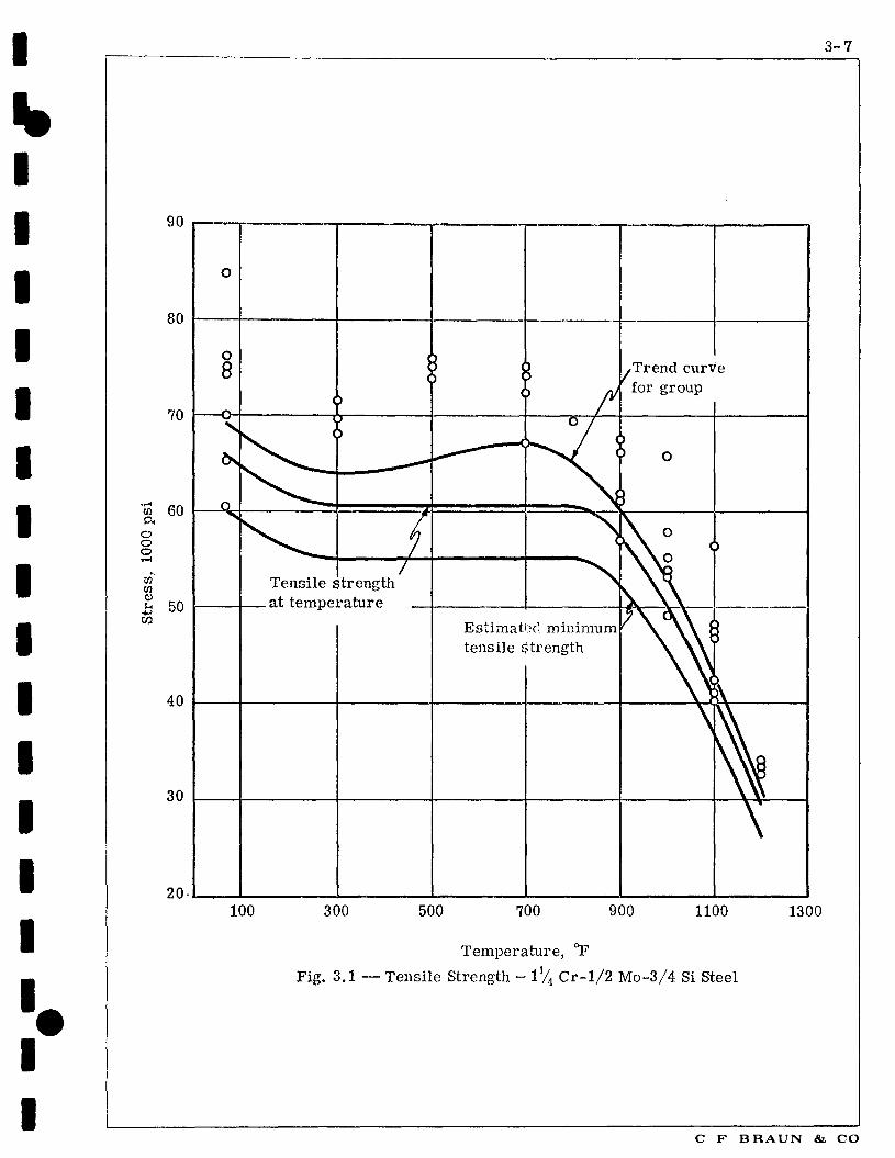
The yield strength or tensile strength trend curve is derived as a j smooth curve drawn through the averages of the data for individual test temperatures. The trend curve then is adjusted by multiplying it by the ratio of the specified minimum value, as given in the material specification, to the trend curve value at 80F. The resulting curve is termed the "estimated minimum strength trend curve." In computing the estimated minimum strength curve, no credit is given to the increase in strength that is frequently observed, particularly for tensile strength, for ferritic steels at intermediate temperatures as the result of strain hardening during the test.
For Code purposes, the property referred to earlier as "yield strength at temperature", that is, the quantity against which fractions specific to particular Sections of the Code are applied in determining the allowable working stress, is synonymous with the minimum estimated yield strength at temperature. On the other hand, the property of "tensile strength at temperature" is interpreted to be the value resulting when an adjustment is made by increasing the estimated minimum tensile strength by 10%.
The foregoing procedures are illustrated in Figure 3.1 with tensile strength data for 1% Cr-1/2 Mo-3/4 Si steel. Figure 3.1 shows the trend curve adopted for the group of steels to which this grade belongs, superimposed upon a plot of the specific test data available for 1% Cr-1/2 Mo-3/4 Si steel. Also shown is the curve for estimated minimum tensile strength at temperature, corresponding to material with a specified minimum tensile strength of 60,000 psi. Note that the estimated minimum curve is drawn horizontally from the computed minimum value preceding the observable increase in strength due to strain-hardening. The final curve shown in Figure 3.1, tensile strength at temperature, was derived by increasing the estimated minimum tensile strength by 10%.
Before trend curves can be established for the temperature variations | of the stresses to cause a secondary creep rate of 0.01% per 1,000 hr i and to cause rupture in 100,000 hr, the available test data (stress 1 and time for rupture, etc) must be evaluated to establish the desired 1 quantities. For the creep-rate data, this evaluation involves ! interpolation or extrapolation, as required, on a plot showing the variation of creep rate with stress. To obtain the stress for rupture in 100,000 hr, data representing shorter-time tests must be
! extrapolated. Extrapolations ordinarily do not exceed a factor of 10 ' for creep data, and a factor of 100 for rupture data. Greater weight ' ! is given in extrapolation to data derived from tests of longer duration. In evaluating creep and rupture strengths, different grades are considered individually, and not in groups.
P 7 C F BRAIN & CO
I 3-7
90
80
70
en a o o o T - (
Cfi' CO a) u
«1
(id
b0
40
30
20-
O
8
Tensile strength . at temperature
Trend curVe for group
Estimated minimum tensile Strength
100 300 500 700 900 1100 1300
Temperature, °F
Fig. 3.1 — Tensile Strength - 1% C r -1 /2 Mo-3/4 Si Steel
C F B R A U N & CO

3-8
3.1.1 SECTION VIII, UNFIRED PRESSURE VESSELS Continued
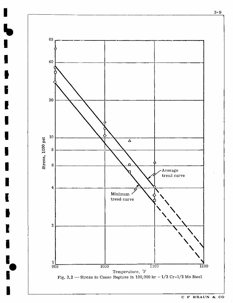
The data for several lots of material, for each of which the 100,000 hour rupture strengths have been derived for two or more temperatures, are plotted on semilog coordinates, Figure 3.2. The arithmetic averages of the results are obtained, and the best straight line is drawn through these points. This is the average trend curve.
The minimum trend curve, shown in Figure 3.2, is obtained from the average trend curve by multiplying the average trend curve by the least ratio of observed minimum value to the average. The ratios are 0.86, 0.77, and 0.78 at 1000, 1050, and 1100 F respectively, and the least value (ie, 0.77) was used.
The trend curve for average stress to produce a secondary creep rate of 0.01% per 1,000 hour is established with the aid of a semilogarithm plot in much the same way as is employed for the rupture data.
Having derived the trend curves for the temperature variation of the several strength properties, it is a straight forward matter to develop the allowable stresses by applying the specific fractions appropriate to the different Sections of the Code.
At higher temperatures, the allowable stresses are based on creep rate as discussed on Page 3-5. In most cases the creep strength is well below the rupture strength. In only a few cases do the stresses listed approach the rupture strength. And in a few cases, the subcommittee has approved stresses without any rupture test data on the specific material and grade, such approval being based on neighboring compositions.
In the transition range of temperatures between elastic and creep behavior, the stress allowances are limited to values obtained from a smooth curve joining the low- and high-temperature ranges but lying on or below the curve of 62.5% of the minimum estimated yield strength at temperature.
In the choice of stresses in the range where a percentage of the tensile strength or yield strength governs, the limitations indicated above have been waived in certain cases, identified by footnote, because it was felt that higher stresses might be justified when deformation was not in itself objectionable, provided all other requirements are met. In such cases the code provides two allowable values.
PV C F BRAUN & CO
I 3-9
60
f 40
.„ 10 CO
a. o o o
w W
Minimum trend curve
'Average trend curve
SOT" " " TOOO 1100 1200 Temperature, CF
Fig. 3.2 —Stress to Cause Rupture in 100,000 hr - 1/2 Cr-1/2 Mo Steel
C F B R A U N & CO

3-10
3.1.2 CODE FOR POWER PIPING (5) With the exception of USAS B31.7, Nuclear Power Piping, the pressure piping codes under the general designation of USAS B31 closely parallel the ASME Boiler and Pressure Vessel Code, Sections I and VIII Division I, in their underlying philosophy.
With the adoption of the Report of Task Force on Flexibility, and its inclusion as Chapter 3 of Section 6 of the 1955 edition of the Code for Pressure Piping, concepts were introduced which marked a departure from previous editions by recognizing the significance of secondary stresses and the effects of fatigue due to cyclic operation.
Thus, instead of basing design on the single criterion of maximum primary membrane stress, the Code now introduced two additional criteria - a limit on the range of secondary stresses due to thermal expansion, and a limit on the number of cycles experiencing that range of secondary stress.
As with the ASME Boiler and Pressure Vessel Codes, no requirements were established with respect to radial thermal stresses.
Wall thicknesses for piping are computed from the Boardman formula similar, but not identical, to the pressure vessel formulas (3-1) and (3-2). Paragraph 104.1.2(a) of reference (5) gives the equation for minimum wall thickness, based on hoop stress, as follows.
tm = PDp +A (3-3)
2(SE+Py)
where t = minimum required wall thickness, inches
P = internal design pressure, psig
D = outside diameter of pipe, inches
S - maximum allowable stress at temperature, from tables given in Appendix A of reference (5), psi
E = longitudinal joint efficiency factor
A - an additional thickness, inches:
1 To compensate for material removed in threading, grooving, etc, required to make a mechanical joint.
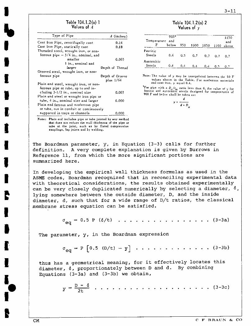
2 To provide for mechanical strength of the pipe. Values of A are listed in Table 104.1.2(a)1 reproduced on Page 3-11. They do not include any amount for corrosion and/or erosion.
y = The Boardman parameter, dimensionless. See Table 104.1.2(a)2, Page 3-11.
PV C F BRAUN & CO
3 - 1 1
Table 104.1.2(a) 1 Table 104.1.2(a) 2 Values of A Values of y
Type of Pipe A ( inches)
0.14 0 18
0.065
Temperature F
Ferritic Steels
Austenit ic Steels
900 ' and
below
0.4
0.4
950
0.5
0.4
1000
0.7
0.4
1050
0.7
0.4
1100
0.7
0.5
1150 and
above
0.7
0.7
Cast Iron Pipe , centrifugally cas t Cast Iron P ipe , s ta t ica l ly cas t Threaded s t e e l , wrought iron, or non-
ferrous pipe — 3/4 in., nominal, and smaller
1 in. , nominal and larger D
Grooved s t ee l , wrought iron, or non-ferrous pipe Depth of Groove Note: The value of y may be interpolated between the 50 F
plus 1/64 values shown in the Table. For nonferrous materials Plain end s tee l , wrought iron, or non- (
a n d c a s t i r o n - * e ' u a l °-4-ferrous pipe or tube, up to and in- F o r P'Pe w i t n a D
0/'m ratio less than 6, the value of y for eluding 3-1/2 in., nominal s ize 0.065 l l " ^ ""? austenitic steels designed for temperatures of
900 F and below shall be taken as:
y =
Plain end s tee l or wrought iron pipe or tube, 4 in., nominal s ize and larger 0.000
Plain end ferrous and nonferrous pipe d + D or tube, run in conduit or continuously supported in trays or channels 0.000
Note: Plain end includes pipe or tube jointed by any method that does not reduce the wall thickness of the pipe or tube at the joint, such as by flared compression couplings, lap joints and by welding.
The Boardman parameter, y, in Equation (3-3) calls for further definition. A very complete explanation is given by Burrows in Reference 11, from which the more significant portions are summarized here.
In developing the empirical wall thickness formulas as used in the ASME codes, Boardman recognized that in reconciling experimental data with theoretical considerations, the results obtained experimentally can be very closely duplicated numerically by selecting a diameter, <5, lying somewhere between the outside diameter, D, and the inside diameter, d, such that for a wide range of D/t ratios, the classical membrane stress equation can be satisfied.
a = 0.5 P (6/t) (3-3a)
The parameter, y, in the Boardman expression
aeq = P [0.5 (D/t) - y] (3-3b)
thus has a geometrical meaning, for it effectively locates this diameter, 6, proportionately between D and d. By combining Equations (3-3a) and (3-3b) we obtain,
y-^r1 (3_3c)
CM C F BRAUN & CO
3-12
And when aeq is replaced by the allowable membrane stress intensity, S, and the terms in Equation (3-3b) are suitably rearranged, Equation (3-3) results.
Although having absolutely no theoretical basis, the parameter, y, nevertheless becomes a convenient means for modifying the diameter to be used in computing the membrane stress, or in computing a wall thickness from an allowable stress value. For example, when y = 0.4, the diameter, <5, is located 0.4 t from the outside surface, and when y = 0.7, 5 is located 0.7 t from the outside surface. The effective diameter thus varies inversely as y, as does the wall thickness.
Having now established the effect of the Boardman parameter, y, its practical application in the wall thickness Equation (3-3) can be discussed. Burrows (11) shows that Equation (3-3b) is best satisfied for stresses in the elastic range when y = 0.4, while in the plastic range a value of y = 0.7 is appropriate. In the range of temperatures at which materials display a transition from elastic to plastic behavior, the value of y takes on an intermediate value between 0.4 and 0.7, as shown in Table 104.1,2(a)2. The derivation of these boundary values for y, and their verification by theoretical and experimental means, is elegantly stated in Reference 11. Their validity is justified for a wide range of D/t ratios, but when this ratio is less than about 6, in the elastic range Equation (3-3c) reduces to
y - D - 2 t - d
2D - 2t d + D
as stated in the footnote to Table 104.1.2 (a)2.
The Power Piping Code (5) uses the following basis for establishing allowable stress values for ferrous materials. At temperatures below the creep range they are the lowest of,
1 25 percent of the specified minimum tensile strength at room temperature
2 25 percent of the minimum expected tensile strength at temperature
3 62.5 percent of the minimum expected yield strength for 0.2 percent offset at temperature
For higher temperatures the stresses are based on 100 percent of the stress to produce a creep rate of 0.01 percent in 1,000 hours, but they are limited to 60 percent of the average stress to produce rupture at the end of 100,000 hours or 80 percent of the minimum stress for rupture in 100,000 hours, whichever is lower. In the transition range of temperatures the stress allowances are limited to values obtained from a smooth curve joining the high and low temperature ranges, but lying on or below the curve of 62.5 percent of the minimum expected yield strength at temperature.
CM C F BRAUN & CO

3-13
3.1.2 CODE FOR POWER PIPING Continued
These criteria are very similar to the provisions of Section I of the ASME Boiler and Pressure Vessel Code, and to those of Section VIII. The methods used for selecting S-values are the same as described in Paragraph 3.1.1, Pages 3-4 through 3-9.
In addition to a limit on primary hoop stress, the Power Piping Code also sets limits on the sum of all primary stresses by requiring that the longitudinal stresses due to pressure, weight and other sustained primary loads shall not exceed the S-value at temperature. Since the longitudinal pressure stress is 50% of the hoop (circumferential) stress, primary bending stresses are thereby limited to 50% of the allowable stress at temperature.
Secondary stresses due to thermal expansion (SE) are required to be held to a value not exceeding the value S, where
SA - f (1.25SC + 0.25Sn) (3-4)
in which Sc = stress value allowed by tables for cold condition
S^ = stress value allowed by tables for hot condition
f = stress reduction factor for fatigue, dependent upon anticipated number of cycles, from Table 102.3.2(c) below
TABLE 102.3.2(c) Stress Range Reduction Factor
NUMBER OF EQUIVALENT FULL TEMPERATURE CYCLES, N
7,000 and less 1.0 7,000 to 14,000 0.9
14,000 to 22,000 0.8 22,000 to 45,000 0.7 45,000 to 100,000 0.6 100,000 and over 0.5
When the sum of the primary stresses is less than S, , then the difference between this sum and S, may be added to the term 0.25Sh in formula (3-4). This means that in the extreme case where the primary stresses approach zero, the allowable stress range, S will approach an upper limit of f(1.25Sc + 1.25S ).
PV C F BRAUN & CO

3-14
3.1.2 CODE FOR POWER PIPING Continued
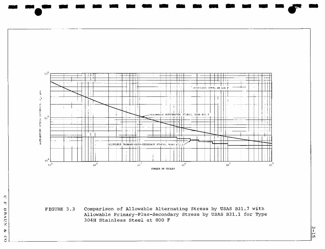
The stress range reduction factor, f, accounts for the reduction of fatigue strength due to cyclic secondary stresses. Although USAS B31.1 does not take peak stresses into consideration, a comparison between the allowable primary-plus-secondary stress by USAS B31.1 and the alternating stress fatigue curve given by the nuclear codes shows a generally good correlation, with a rather conservative trend in the lower cycle range (less than about 2000 cycles). Figure 3.3 shows the comparison for stainless steel, Type 304H, at 800 F. The allowable primary-plus-secondary curve for USAS B31.1 has been determined from
Sa = f(1.25Sc + 0.25Sh) + Sh
By comparison, USAS B31.7 takes Sa to be one-half of the peak stress intensity, Sp, computed as the sum of the primary and secondary stresses and their peak stress increments. As pointed out by Kooistra (10), a failure to take peak contributions into account may lead to a serious overprediction of fatigue life: thus in the high-frequency, low-stress, range USAS B31.1 may prove somewhat non-conservative, particularly for components with high local peak stress concentrations.
The thermal expansion stress range, SE, is required by Paragraph 119.7 to be computed in accordance with certain rather general rules. These require that a competent flexibility analysis be performed by a method which takes proper account of the flexibility and stress intensification factors applicable to individual components in the system. Model tests, and simplified chart-type methods, are permitted provided that their competence has been demonstrated by satisfactory experience. Except for simple, symmetrical systems, such as expansion loops, these requirements imply the application of relatively rigorous methods of analysis, and it has become the widely-accepted practice to employ electronic digital computers in the solution of flexibility problems.
3.2 CODES BASED ON STRESS CATEGORIZATION
Instead of considering only primary membrane stress in establishing Code stress criteria, the nuclear pressure vessel and piping codes consider primary, secondary, and peak stresses, and also provide a basis for cycle life determination, thus providing a more detailed picture of the stresses induced in the system.
3.2.1 SECTION III, NUCLEAR VESSELS (6) The philosophy which guided the formulation of Section III of the ASME Boiler and Pressure Vessel Code for Nuclear Vessels is contained in a separate document, Reference (7), which accompanies the Code Section and is in part summarized below.
PV C F BRAUN & CO
6
H 01 a
to
H tO !3 W t><
CO
a CO
M
< H EH
4
1C 1
i
^ ^ ~ ALLOWABLE ALTERNATING
ST? U N L E S S STEEL AT
S T R E S S , USAS B 3 1 . 7
1 r ^ ALLOWABLE PRIMARY-PLUS-SECONDARY S T R E S S . USAS B 3 1 . 1 /
2 ) 1C 3
) N UMBER OF CYCLES
4 10
1
8 0 0 • •
i o 5 6 10
FIGURE 3.3 Comparison of Allowable Alternating Stress by USAS B31.7 with Allowable Primary-Plus-Secondary Stress by USAS B31.1 for Type 304H Stainless Steel at 800 F
3-16
3.2.1 SECTION III, NUCLEAR VESSELS Continued
The development of this Code Section was mainly the work of the ASME Special Committee to Review Code Stress Basis. The committee was established to investigate what changes in the code design philosophy might permit the use of higher allowable stresses without reduction in safety. The committee members represented two main schools of thought: some believed the new code should remain based on design rules, while the others wanted it based on modern stress analysis methods. When, after much debate, the "design rules" school failed to produce any real improvements in methods, the "stress analysis" school won the day. The resulting detailed evaluation of stresses by the new code rules permits assignment of more rational margins of safety, in place of larger factors which really reflected lack of knowledge.
The development of analytical and experimental techniques has made it possible to determine stresses in considerable detail. When the stress picture is thus brought into sharper focus, it is no longer reasonable to retain the same values of allowable stress as had been used previously for the less detailed picture. Nor is it sufficient merely to raise the allowable stresses to reasonable values for the peak stresses, since peak stress by itself is not an adequate criterion of safety. A calculated value of stress means little until it is associated with its location and distribution in the structure and with the type of loading which produced it. Different types of stresses have different degrees of significance, and therefore must be assigned different allowable values. For example, the average hoop stress through the thickness of a vessel wall due to internal pressure must be held to a lower value than the stress at the root of a notch in the wall. Similarly, a thermal stress often can be allowed to reach a higher value than one which is produced by dead weight or pressure. Therefore the setting of allowable stress values requires dividing the stresses into categories, and assigning different allowable values to different categories.
The design criteria of Section III differs from those of Section I and Section VIII, Division 1, in the following respects.
1) Section III uses the maximum shear stress theory (Tresca) instead of the maximum stress theory of failure.
2) Section III requires the detailed calculation and classification of all stresses and the application of different stress limits to different classes of stress. Section I and Section VIII, Division 1, merely give formulas for minimum allowable wall thickness.
3) Section III requires the calculation of thermal stresses and categorizes them as secondary and peak stresses, while Section I does not mention them and Section VIII, Division 1 says only that they be "considered".
PV C F BRAUN & CO
3-17
3.2.1 SECTION III, NUCLEAR VESSELS Continued
4) Section III considers the possibility of fatigue failure and gives rules for its prevention, while Section I and Section VIII, Division 1, do not.
The stress limits of Section III are intended to prevent three types of failure, as follows.
1) Bursting and gross distortion from a single application of pressure and other primary loads are prevented by the limits placed on primary stresses.
2) Progressive distortion is prevented by the limits placed on primary-plus-secondary stresses. These limits assure shakedown to elastic action after a few repetitions of the loading.
3) Fatigue failure is prevented b/ the limits placed on peak stresses.
Satisfactory empirical limits for creep-rate and stress-rupture have been established and used in Section I and Section VIII, Division 1 (see 3.1.1). It was not possible for the Special Committee to arrive at satisfactory limits for secondary and peak stresses for Section Iin in the creep range, thus the present edition of Section III is restricted to temperatures at which creep will not be significant. This has been done by limiting the tabulated allowable stress intensities to below the temperature of creep behavior - 700 F for carbon steels and low-alloy steels, and 800 F for austenitic steels.
The design stress intensity values for Section III are taken as the lowest of the following.
1) 1/3 of the specified minimum tensile strength at room temperature.
2) 1/3 of the tensile strength at temperature.
3) 2/3 of the specified minimum yield strength at room temperature.
4) (a) For ferritic steels and nonferrous metals and alloys, 2/3 of the yield strength at temperature.
(b) For austenitic steels, nickel-chromium-iron alloys, and nickel-iron chromium, 90 percent of the yield strength at temperature, but not to exceed 2/3 of the specified minimum yield strength.
PV C F BRAUN & CO
3-18
3.2.1 SECTION III, NUCLEAR VESSELS Continued
The fatigue curves are obtained from uniaxial strain-cycling data in which the imposed strain amplitude (half range) is multiplied by the elastic modulus to put the values into stress units. A best fit to the experimental data is obtained by applying the method of least squares to the logarithms of the stress values. The curves are adjusted where necessary to include the maximum effect of mean stress. The design stress values are obtained from the best-fit curve by applying a factor of two on stress or a factor of 20 on cycles, whichever is the more conservative at each point.
As has been previously stated, in an effort to avoid the further complexities introduced by high temperatures, Section III at present is limited to temperatures no higher than 700 F for carbon steels and low-alloy steels, and 800 F for austenitic steels. However, a request was received by the committee for consideration of temperatures above these limits. The committee's reply is stated in Code Case Interpretation 1331, permitting the use of the code rules, with modifications, up to temperatures of 1100 F for carbon and low-alloy steels and 1200 F for austenitic steels. A reproduction of Revision 4 of this code case is given on the two following pages.
The design stress intensity values which are established for use at the higher temperatures permitted by Code Case 1331 are those of Section I, or Section VIII, Division 1, if the material is not listed in Section I. Because of the difference between the stress criteria used for Section I (or VIII) and Section III, large step changes occur in the allowable stresses at the transition temperature for some materials. The code bodies recognize these large step changes do occur and that this situation will continue to exist until the rules in the Nuclear Code are extended to the upper temperature limits, at which time the code case can be withdrawn.
Current work underway affecting the code case includes revision of the fatigue curves. This will cover the addition of a 100 F line, and a method to account for the change in modulus of elasticity with temperature for different materials.
PV C F BRAUN & CO
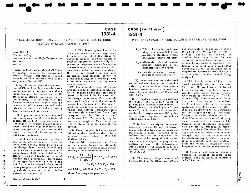
CASE 1331-4
INTERPRETATIONS OF ASME BOILER AND PRESSURE VESSEL CODE
Approved by Council August 15, 1967
(b) The limits given herein for ose I J J I - 4 primary stress intensity are applicable
(Special Ruling) t o m a t e r l a l s fo which the stress re-Nuclear Vessels in High Temperature quired to produce long time rupture of Service notched specimens under steady load Section 111 at service temperature is no lower than
the stress required to rupture unnotched Inquiry: Under what rules shall Class specimens under the same conditions
A nuclear vessels be constructed If it is not feasible to use such whose design temperatures exceed materials, consideration should • be those for which allowable stress values given to reducing the allowable primary are given in Section IIP stress intensity and/or limiting stress
p _ „ i . n i . L . concen t ra t i ons tleply Hules covering the construe- ,„* _ , , , , , , , ,
,,„„ „, r\ A i I L L I*' Ine allowable value of general lion ot Llass A nuclear vessels which , B c.
. primary membrane-stress intensity, om, are to operate at temperatures above , . , . , . ,* , . , , , , , , , m
, . j i r c in vN-414 1) shall be the allowable stress those now provided [or in Section III ~ , . . , r . , , - , given in section 1 for the material at are in preparation by the Committee In . . r- i , . . . , . . the design temperature, r or materials the interim, it is the opinion of the , , c r , n i . r- . . . . . • i i ii u n o t listed in section 1, the allowable Committee that such vessels shall be constructed of the materials and to the stress from Section V I , Division 1, rules of Section III with the following shf" b e " s e d - The allowable stress _„j,r,„ , j ° values and external pressure charts modifications and precautions , , , r. „ , .-,
r for materlals covered by Code Case (1) In general, it must be recognized interpretations for Section I and/
that designing to the standards of or Section VIII, Division 1, may be Section III for high-temperature opera used even though the Case interpretation frequently requires analytical tech- tion is stated to be not applicable to niques and knowledge of material be- Section III havior not presently contained in the ( 3 ) Y x a s p r o v l d e d l n paragraph Code Therefore the following precau- ( 6 ) b e l o w _ t h e a!Iowable value of local tions shall be taken membrane stress intensity (N-414.2)
(a) When deformations can affect shall be 1.5 Sm
the safety of the vessel, limits for (4) (a) When stresses are calculated these deformations shall be given in on an elastic basis, the allowable the Design Specification (N-141) and value of primary membrane plus primary calculations to show compliance with bending stress intensity shall be these limits shall be included in the / \ Stress Report (N-142). In particular, if ^ $ _ lT~ c \ freedom from progressive deformation m \ ^00 / of the type discussed in N-4I7.3 and N-417.4 is to be assured, the rules of for Tc < T < Tc + 200 those paragraphs shall be supplemented by calculations in which creep deformations are considered where T= design temperature, F
and 1 33 Sm -0 .33 S for T > T„ + 200
Meeting of June 3, 1967 1
CASE ( c o n t i n u e d )
1331-4 INTERPRETATIONS OF ASME BOILER AND PRESSURE VESSEL CODE
Tc = 700 F for carbon and low-alloy steels and 800 F for austenitic stainless steels and nickel-chrome-iron alloy
Sm = allowable value of general primary membrane stress intensity (see (2) above)
S= calculated value of primary membrane stress intensity
(b) Rhen stresses are calculated on an inelastic basis, the allowable value of primary membrane plus primary bending stress intensity at any time during the specified life of the vessel shall be Sm
(5) Except as provided in paragraph (6) below, the allowable value of primary-plus-secondary stress intensity (N-4I4.4) shall be the higher of three times 5„ or three times the allowable amplitude of fatigue stress at 10s cycles for the metal temperature involved, as determined in (7) below
(6) In lieu of satisfying the stress intensity limits of (3) and (5) above, the structural action may be analyzed on a plastic basis, including creep deformations, and the design shall be considered to be acceptable if shakedown occurs, as opposed to progressive deformation, and if the deformations which occur prior to shakedown do not exceed any specified limits (See (l)(a) above).
(7) The design fatigue curves of Section III (Figs N-415(a) and (b)) are
not applicable at temperatures above the limits of V202(a), and the curu-. of Figs 1 and 2 of this Case shall be used in their place Values for temperatures intermediate between the curves shown may be interpolated The fatigue curve to be used shall be that corresponding to the maximum metal temperature occurring during the cycle at the point on the vessel being analyzed
NOTE The Sa values of Fig 1 are based primarily on test data from 2'i Cr — 1 Mo steel and are believed to be conservative for ductile carbon and low-alloy steels having nominal Cr contents not exceeding 5^ The SQ
values of Fig. 2 are based primarily on test data from austenitic stainless steel and are believed to be also applicable to nickel-chrome-iron alloy. If data are submitted to the Committee for the establishment of allowable fatigue stresses for other materials, it should be noted that special alloying elements and heat treatments used to improve creep resistance frequently have a deleterious effect on resistance to strain cycling Therefore, data showing superior creep resistance or other strength properties are not acceptable for substantiating i values In order to be acceptable, such data shall include the results of strain-controlled fatigue tests at the design temperature
(8) Vessels and tubular products subject to external pressure shall conform to the design rules of Article I—11 of Section III
2
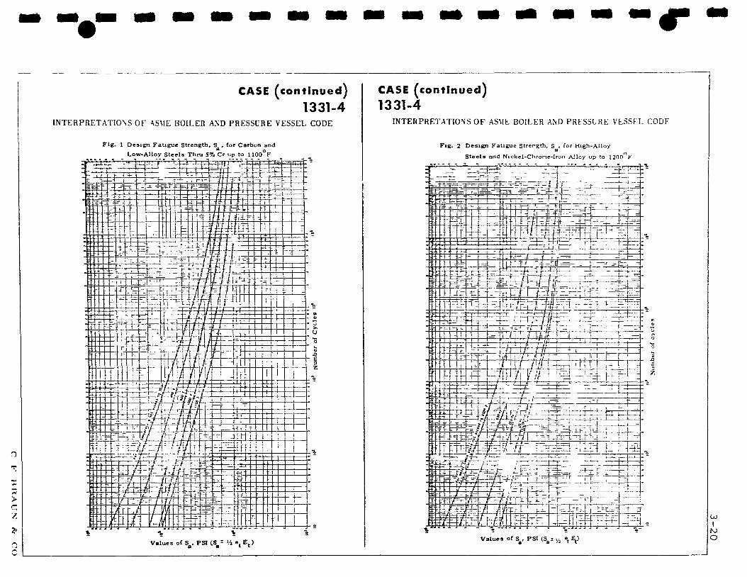
CASE (continued)
1331-4 INTERPRETATIONS OF *SV1E BOILER AND PRESSURE VESSEL CODE
Fig . 1 Design Fatigue Strength, S , for Carbon and Low-Alloy Steels Thru S7o Cr up to HOG F
Values of S . PSI (S_= Vi e E )
CASE (continued) 1331-4
INTERPRETATIONS OF ASME BOILER AND PRFSSLRE VESSFL CODF
Fig. 2 Design Fa t igue Strength, S , for High-Alloy a
Stee l s and Nickel-Chrone-Iron Alloy up to 1200 F
Values of S , PSI (S ; y2 ef E )
3-21
3.2.2 CODE FOR NUCLEAR POWER PIPING, USAS B31.7 (8) A draft of the new USA Standard Code for Nuclear Power Piping was issued for trial use and comment in February 1968, and the work of evaluating comments and revising the text is continuing. For this reason it is perhaps too early to attempt a detailed review of its provisions. However, no significant changes in basic design philosophy are at present visualized, since this code relies heavily upon the satisfactory experience with Section III of the ASME Boiler and Pressure Vessel Code. The underlying principles are in fact identical. Because of the inherent complexity of piping configurations, however, an attempt has been made in B31.7 to achieve some simplification in the analytical procedures, at the expense of some conservatism, and it is here that some differences between B31.7 and Section III arise.
The assumptions made in the development of the simplified equations for computing primary, primary-plus-secondary, and peak stresses, are given by Moschini (9) as follows.
1) It was assumed that the maximum stress due to the various loads were all acting at the same point on the component.
2) Sign was assumed positive in the summation of stresses.
3) Moments are combined vectorially as the square root of the sum of the squares.
4) Stress indices used are the maximum for the particular piping component.
The first step in performing a simplified analysis to satisfy B31.7 is to establish the anticipated performance program for the system, by listing each of the thermal cycles that can be expected to occur during the life of the plant, including start-up and shut-down and all forseeable emergency transients, as well as normal operational fluctuations in temperature. For each identified transient the beginning and ending temperature must be established, and an estimate made of the probable number of each occurrence. Flexibility analyses are now made for the system for each different transient condition and the loads and stresses acting on each component are computed. By reviewing this data, those individual components that are being subjected to the most severe load conditions can now be selected for detailed analysis.
PV C F BRAUN & CO
I 3-22
3.2.2 CODE FOR NUCLEAR POWER PIPING Continued
The primary stress intensity is now computed for each selected component from equation (3-5) - equation (9) of USAS B31.7.
Bl PDc 2t
D +
o B2 7f Mi 1 1.5Sm (3-5)
where Blt B 2
D
MJ
primary stress indices for the specific component under investigation, given in Table D-201, Appendix D, Reference (8)
design pressure, psi
outside diameter of pipe, in
nominal wall thickness of component, in
moment of inertia, in
resultant moment loading due to loads caused by weight and earthquake (single amplitude) effects or other mechanical loads, obtained by vectorial addition of the moments in each of the three mutually perpendicular principal axes of the component, in-lb
allowable primary membrane stress intensity, psi, from Table A-l, Appendix A, Reference (8)
The value of Bj is 0.5 for straight pipe, so that the first term in equation (3-5) yields the longitudinal pressure stress; for branch connections, butt-welding elbows, tees and reducers, and curved pipe, however, Bi = 1.0, and the first term thus gives the hoop stress. The second term gives the longitudinal stress due to bending under primary moment loads. If Bi is considered merely as a stress intensification factor, then the first term gives the longitudinal stress for all components; in this sense, an arbitrary stress raiser of 2 for all pipe fittings other than straight pipe appears to be rather conservative. Clarification of this point is needed.
m
_£vL C F BRAUN & CO

3-23
3.2.2 CODE FOR NUCLEAR POWER PIPING, USAS B31.7 Continued
If the criterion of 1.5 Sm is satisfied, the primary-plus-secondary stress intensity range is next computed from equation (3-6) -equation (10) of USAS B31.7.
^ PDo x „ D0 x 5n " C! + C2 - M± + 1 J I - r Ea
a a DO
AT]_
£ 3 Sm (3_6) + c3Eab
where
Sn = primary-plus-secondary stress intensity, psi
CJL, C-2' c3 = secondary stress indices for the specific component under investigation, given in Table D-201, Appendix D, of reference (8).
M^ = range of moment loading resulting from weight, earthquake effects (double amplitude), other mechanical loads, thermal expansion, and anchor movements. Mi is the vector sum of the 3 contributing moments, each of which is the algebraic sum of all moments acting about the axis in question, inch-pounds.
Ea = modulus of elasticity (E) times the mean coefficient of thermal expansion (a), psi/ F.
E b = the average modulus of elasticity of the two parts of the gross discontinuity, psi.
I AT]_ = absolute value of the difference in temperature ' ' between inside and outside surface of component
assuming moment-generating equivalent linear temperature distribution, F. See Figure 3.3 on Page 3-22.
a ,ab = mean coefficient of expansion on side a and b respectively of a gross discontinuity, inch/inch/ F
T , T, = average temperature minus room temperature on side a a and b respectively of a gross discontinuity, F.
v = Poisson's ratio
P, D , t, I, S are as previously defined for equation (3-5)
CM C F BRAUN & CO
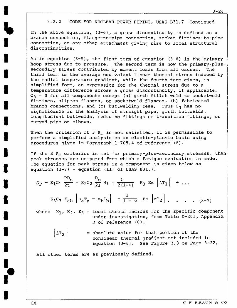
_ _ . 3-24
3.2.2 CODE FOR NUCLEAR POWER PIPING, USAS B31.7 Continued
In the above equation, (3-6) , a gross discontinuity is defined as a branch connection, flange-to-pipe connection, socket fittings-to-pipe connection, or any other attachment giving rise to local structural discontinuities.
As in equation (3-5), the first term of equation (3-6) is the primary hoop stress due to pressure. The second term is now the primary-plus-secondary stress contributed by moment loads from all causes. The third term is the average equivalent linear thermal stress induced by the radial temperature gradient, while the fourth term gives, in simplified form, an expression for the thermal stress due to a temperature difference across a gross discontinuity, if applicable. C3 = 0 for all components except (a) girth fillet weld to socketweld fittings, slip-on flanges, or socketweld flanges, (b) fabricated branch connections, and (c) buttwelding tees. Thus C3 has no significance in the analysis of straight pipe, girth buttwelds, longitudinal buttwelds, reducing fittings or transition fittings, or curved pipe or elbows.
When the criterion of 3 S m is not satisfied, it is permissible to perform a simplified analysis on an elastic-plastic basis using procedures given in Paragraph 1-705.4 of reference (8).
If the 3 Sm criterion is met for primary-plus-secondary stresses, then peak stresses are computed from which a fatigue evaluation is made. The equation for peak stress in a component is given below as equation (3-7) - equation (11) of USAS B31.7.
PD, P - KlCi 2t~ + K2°2 21 Mi + 2lT^r K3 So - Ea AT^
K3C3 E ab aaTa ~ abTb + 1 - v Ea AT- • (3-7)
where K 1'
AT-
K2, K3 = local stress indices for the specific component under investigation, from Table D-201, Appendix D of reference (8).
= absolute value for that portion of the nonlinear thermal gradient not included in equation (3-6). See Figure 3.3 on Page 3-22.
All other terms are as previously defined.
CM C F BRAUN & CO
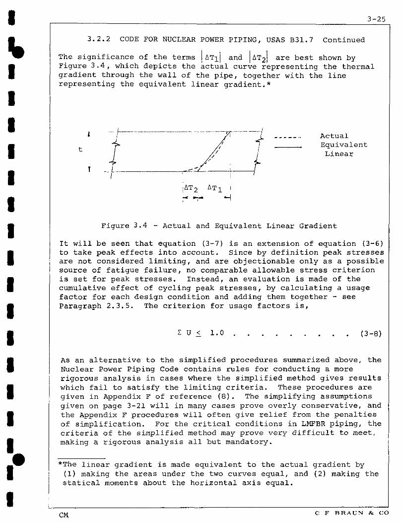
3-25
3.2.2 CODE FOR NUCLEAR POWER PIPING, USAS B31.7 Continued
The significance of the terms AT^ and AT2 are best shown by Figure 3.4, which depicts the actual curve representing the thermal gradient through the wall of the pipe, together with the line representing the equivalent linear gradient.*
t
T
* / " ~ ~ / \ 7. A c t u a l / E q u i v a l e n t
L i n e a r
|AT2 AT! «-l
Figure 3.4 - Actual and Equivalent Linear Gradient
It will be seen that equation (3-7) is an extension of equation (3-6) to take peak effects into account. Since by definition peak stresses are not considered limiting, and are objectionable only as a possible source of fatigue failure, no comparable allowable stress criterion is set for peak stresses. Instead, an evaluation is made of the cumulative effect of cycling peak stresses, by calculating a usage factor for each design condition and adding them together - see Paragraph 2.3.5. The criterion for usage factors is,
Z U < 1.0 (3-8)
As an alternative to the simplified procedures summarized above, the Nuclear Power Piping Code contains rules for conducting a more rigorous analysis in cases where the simplified method gives results which fail to satisfy the limiting criteria. These procedures are given in Appendix F of reference (8). The simplifying assumptions given on page 3-21 will in many cases prove overly conservative, and the Appendix F procedures will often give relief from the penalties of simplification. For the critical conditions in LMFBR piping, the criteria of the simplified method may prove very difficult to meet, making a rigorous analysis all but mandatory.
*The linear gradient is made equivalent to the actual gradient by (1) making the areas under the two curves equal, and (2) making the statical moments about the horizontal axis equal.
CM C F BRAUN & CO
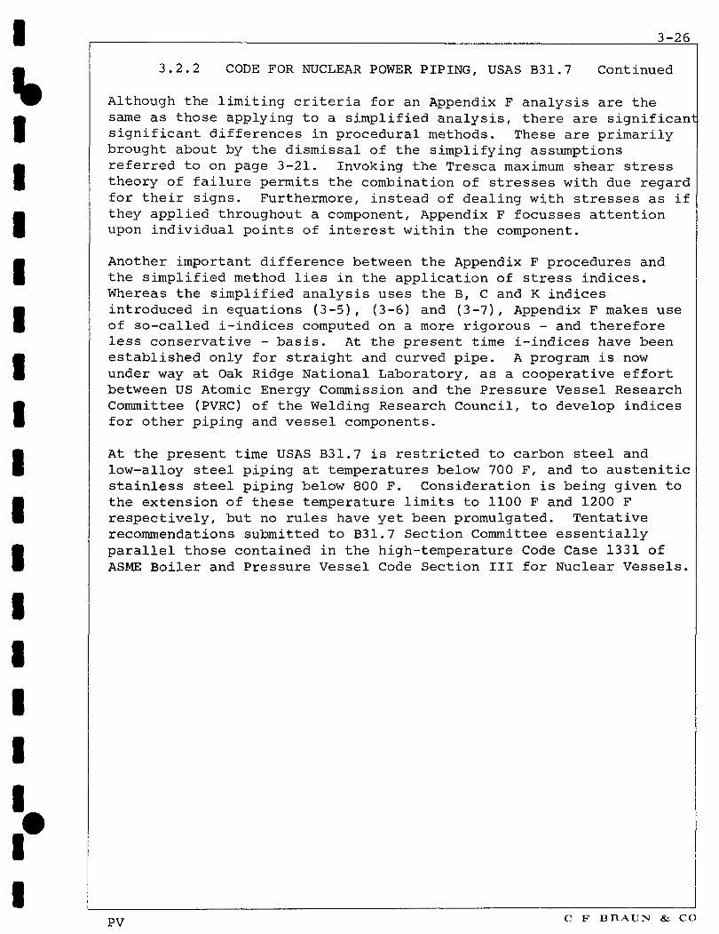
3-26
3.2.2 CODE FOR NUCLEAR POWER PIPING, USAS B31.7 Continued
Although the limiting criteria for an Appendix F analysis are the same as those applying to a simplified analysis, there are significan significant differences in procedural methods. These are primarily brought about by the dismissal of the simplifying assumptions referred to on page 3-21. Invoking the Tresca maximum shear stress theory of failure permits the combination of stresses with due regard for their signs. Furthermore, instead of dealing with stresses as if they applied throughout a component, Appendix F focusses attention upon individual points of interest within the component.
Another important difference between the Appendix F procedures and the simplified method lies in the application of stress indices. Whereas the simplified analysis uses the B, C and K indices introduced in equations (3-5), (3-6) and (3-7), Appendix F makes use of so-called i-indices computed on a more rigorous - and therefore less conservative - basis. At the present time i-indices have been established only for straight and curved pipe. A program is now under way at Oak Ridge National Laboratory, as a cooperative effort between US Atomic Energy Commission and the Pressure Vessel Research Committee (PVRC) of the Welding Research Council, to develop indices for other piping and vessel components.
At the present time USAS B31.7 is restricted to carbon steel and low-alloy steel piping at temperatures below 700 F, and to austenitic stainless steel piping below 800 F. Consideration is being given to the extension of these temperature limits to 1100 F and 1200 F respectively, but no rules have yet been promulgated. Tentative recommendations submitted to B31.7 Section Committee essentially parallel those contained in the high-temperature Code Case 1331 of ASME Boiler and Pressure Vessel Code Section III for Nuclear Vessels.
PV C F BRAUN & CO

4-1
4 DESIGN CRITERIA FOR LMFBR PIPING
It has been shown in the previous sections of this report that the nuclear codes - Section III of the ASME Boiler and Pressure Vessel Code for Nuclear Vessels, and USASI Code for Nuclear Power Piping, USAS B31.7 - exemplify the most recent developments in vessel and piping design regulatory procedures. Code Case 1331 has attempted to extend the applicability of these codes from 700F for carbon and low-alloy steels, and 800F for austenitic steels, out to HOOF and 1200F respectively. These codes have been written to provide proper design safeguards for water-cooled nuclear power plants of the type that are being built today. In approaching the development of the LMFBR Piping Design Guide, it is now necessary to determine whether the present nuclear codes are appropriate for the LMFBR.
A simple answer would be that they are not, merely on the grounds that they were not developed with the severe environment of the fast breeder reactor in mind. While this answer is no doubt a proper one, it is technically unsatisfactory. It can be argued that many industrial plants have been successfully designed and operated utilizing large-diameter piping systems which convey hazardous fluids at temperatures and pressures considerably higher than those contemplated for the LMFBR. And it has not been demonstrated that the present nuclear codes could not be found entirely adequate, despite the fact that they were not developed specifically for the LMFBR.
There are three features of the LMFBR system which sets it apart from conventional water-cooled nuclear power systems - (1) the liquid sodium coolant; (2) higher operating temperatures; and (3) a 30-year service life under severe cyclic operating conditions.
Liquid sodium has a very high coefficient of thermal conductivity (indeed, this is the very reason for its selection as a coolant in the LMFBR), and rapid changes in fluid temperatures, such as those brought about by some upset condition in the reactor or in the primary or secondary coolant systems, will induce thermal stresses in the pipewall considerably higher than those accompanying similar changes in more conventional fluids. It is a characteristic of thermal stresses induced by rapid temperature excursions that they become more severe as the wall thickness increases.
In the present nuclear codes, as supplemented by Code Case 1331, values for allowable stress intensities at elevated temperatures are based on relatively short term creep and rupture data which has been extrapolated logarithmically to 100,000 hours at temperature. They thus reflect an anticipated service life of from 12 to 15 years, depending on the service factor. In designing for a 30-year service life, therefore, it is necessary that the allowable stress values be appropriately downgraded.
PV C F BRAUN & CO
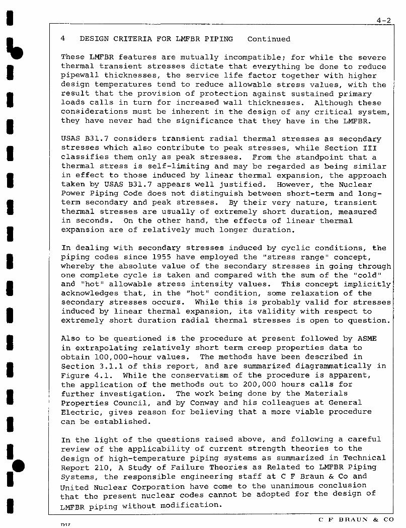
4-2
4 DESIGN CRITERIA FOR LMFBR PIPING Continued
These LMFBR features are mutually incompatible; for while the severe thermal transient stresses dictate that everything be done to reduce pipewall thicknesses, the service life factor together with higher design temperatures tend to reduce allowable stress values, with the result that the provision of protection against sustained primary loads calls in turn for increased wall thicknesses. Although these considerations must be inherent in the design of any critical system, they have never had the significance that they have in the LMFBR.
USAS B31.7 considers transient radial thermal stresses as secondary stresses which also contribute to peak stresses, while Section III classifies them only as peak stresses. From the standpoint that a thermal stress is self-limiting and may be regarded as being similar in effect to those induced by linear thermal expansion, the approach taken by USAS B31.7 appears well justified. However, the Nuclear Power Piping Code does not distinguish between short-term and long-term secondary and peak stresses. By their very nature, transient thermal stresses are usually of extremely short duration, measured in seconds. On the other hand, the effects of linear thermal expansion are of relatively much longer duration.
In dealing with secondary stresses induced by cyclic conditions, the piping codes since 1955 have employed the "stress range" concept, whereby the absolute value of the secondary stresses in going through one complete cycle is taken and compared with the sum of the "cold" and "hot" allowable stress intensity values. This concept implicitly acknowledges that, in the "hot" condition, some relaxation of the secondary stresses occurs. While this is probably valid for stresses induced by linear thermal expansion, its validity with respect to extremely short duration radial thermal stresses is open to question.
Also to be questioned is the procedure at present followed by ASME in extrapolating relatively short term creep properties data to obtain 100,000-hour values. The methods have been described in Section 3.1.1 of this report, and are summarized diagrammatically in Figure 4.1. While the conservatism of the procedure is apparent, the application of the methods out to 200,000 hours calls for further investigation. The work being done by the Materials Properties Council, and by Conway and his colleagues at General Electric, gives reason for believing that a more viable procedure can be established.
In the light of the questions raised above, and following a careful review of the applicability of current strength theories to the design of high-temperature piping systems as summarized in Technical Report 210, A Study of Failure Theories as Related to LMFBR Piping Systems, the responsible engineering staff at C F Braun & Co and United Nuclear Corporation have come to the unanimous conclusion that the present nuclear codes cannot be adopted for the design of LMFBR piping without modification.
mr C F BRAUN & CO
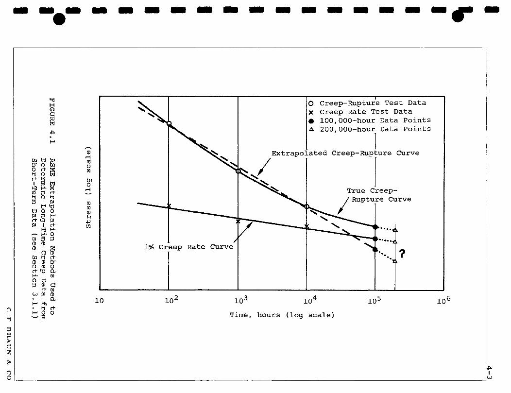
I 4-3
en en
rd -P
-P
•P
£
C
rd -H
-H
Q
rd
0 0
-P
ft ft
•P
rd !0
Q
|tj Id
CD
-P
-P
EH -P
rd
rd w
P
Q
.(D
0)
•P
CD 0
0 ft4Jfii 5
JS ' '
P5 05
O
O
1 o
o
a ft o
o
a)
a> -
-CD
CD
O
O
M
M
O
O
UU
HN
O
X •
<
//
/7
> CD
lj 3 4J , P
i
3 i Qj
0) (1)
u CD
•P
rd
0 &
rd
u
-P
x: \ V
//
//
y
ft CD
CD
U CD
3 M
EH
y //
(1) > 3 CD
3 65
<i
• .
X/.4 /
//
//
/
// J
/X
C-
*1 rl
• *
• •
A
A
f/
s CD
> 3 CD
-P
13 OS
ft CD
, fl)
i
'u'
u
s
o
in o rH
o
n o
rd 0 w tn 0 .-I
CO
0 43
•A
EH
CN O
(ai^os Box) ssaaq.s
FIGURE 4.1
ASME Extrapolation Methods Used to
Determine Long-Time Creep Data from
Short-Term Data (see Section 3.1.1)
C F BRAUN & CO

4-4
4 DESIGN CRITERIA FOR LMFBR PIPING Continued
It must be clearly understood that the conclusion stated above has been reached solely upon consideration of the problems associated with the unusually severe requirements for LMFBR systems, and in no way reflects upon the adequacy of present practices for the types of plants and for the service conditions for which they have been developed.
It will be the purpose of the developmental tasks still to be carried out under this contract to further investigate the special problems of LMFBR piping systems. Subject to their ratification and possible amendment by the findings of these investigations, some tentative interim assumptions can be made at this time as to a satisfactory design basis for the LMFBR Piping Design Guide. These may be summarized as follows.
STRESS CATEGORIES The following are the stress categories for which appropriate design analysis procedures will be established.
1) Primary Stress
(a) Sustained primary membrane stress (b) Transient primary membrane stress (c) Local primary membrane stress (d) Primary bending stress
2) Secondary Stress
(a) Sustained secondary stress
(b) Transient secondary stress
3) Peak Stress
(a) Sustained peak stress (b) Transient peak stress
The definition of primary, secondary and peak stress will be as stated in Section 2.3 of this report.
STRENGTH THEORIES For the LMFBR Piping Design Guide either the maximum shear stress theory (Tresca) or the distortion energy theory (von Mises criterion) may be applied in the formulation of design analysis procedures for the transient or short-term loadings, or for temperatures where creep is not a factor, as may prove the more convenient or expedient for any given application. For the sustained loadings either the maximum principal stress theory or the distortion energy theory may be used depending upon whether the calculated stresses are being limited by criteria based on stress rupture or creep strain respectively.
PV C F B R A U N & CO
i 4-5
4 DESIGN CRITERIA FOR LMFBR PIPING Continued
CREEP AND RELAXATION Creep effects will be taken into account in relation to sustained primary stresses. Creep relaxation will be taken into account in regard to sustained secondary and sustained peak stresses.
RATCHETTING It will be a requirement of the LMFBR Piping Design Guide that plastic strain cycling will be permitted only to the extent that it can be satisfactorily demonstrated that shakedown will occur. Procedures to show how this may be verified will be developed for the Design Guide.
WALL THICKNESS The Boardman equation, or a modification to it, will be used for the calculation of wall thicknesses.
PRIMARY BENDING STRESSES As a design procedure, longitudinal bending stresses due to dead load or seismic effects will be limited independently to one-fourth of the allowable primary membrane stress intensity. This can be achieved by the provision of pipe supports and hydraulic dampeners sufficiently close together as to minimize these effects. The LMFBR Piping Design Guide will furnish appropriate guidelines. Alternative procedures limiting the combination of primary bending and primary membrane stresses will also be provided.
SECONDARY AND PEAK STRESSES Secondary and peak stresses will be computed as stress ranges on an elastic basis, in accordance with present practice, but a distinction will be made between those due to relatively sustained loads and those induced by transient conditions.
ALLOWABLE PRIMARY STRESS INTENSITY The allowable primary membrane equivalent stress will be based on the same fractions of yield and ultimate strengths and creep properties as used in the current ASME and USASI nuclear codes that are applicable in the creep range, based on 200,000-hour data. The method of extrapolation will be investigated in Task 312, with the object of obtaining a reliable correlation.
ALLOWABLE SECONDARY STRESSES The allowable values for short-term transient secondary stress ranges will be established as the sum of the yield strengths of the materials at the extremes of the ranges of temperature during the transient, modified to reflect the increase in strength due to the strain hardening effected by some permissible total strain. Allowable values of yield strengths for sustained secondary loads will be downgraded to reflect the effects of relaxation. Where this cannot be established with certainty, the allowable range will be taken as the yield strength at the lower (cold) extreme of temperature range.
C F BRAUN & CO

4-6
4 DESIGN CRITERIA FOR LMFBR PIPING Continued
ALLOWABLE PEAK STRESSES For transient peak stress ranges, the fatigue curve to be used will be determined as an average between the fatigue curves associated with the temperatures at the extremes of the temperature range at the point being analyzed. For sustained peak stresses, the procedure will be the same except that the fatigue curves will be downgraded to reflect the effects of relaxation.
(In general, this means that the low-temperature fatigue curves are those in current use. If no acceptable procedure can be readily established for downgrading the high-temperature curve, it can be arbitrarily set at zero. Thus the fatigue curve for sustained peak stresses would have ordinates equal to one-half the values of the low-temperature curve. This may yield results that are too conservative, but an improvement over the method suggested here will have to await the conductance of cyclic fatigue tests that properly reflect the effects of creep and temperature ranges).
COMPUTATIONAL METHODS Except as modified by the criteria stated in the foregoing paragraphs, stresses will in general be computed in accordance with the procedures given in USAS B31.7, Appendix F.
OTHER RELATED PROGRAMS The evolution of engineering technology is a dynamic process. Many programs are at present under way in the general area of high-temperature vessel and piping design which will undoubtedly have an important impact upon the formulation of criteria and procedures for LMFBR piping. Among the more important programs, the work of ASME Section III Subgroup on Elevated Temperature Design may be expected to yield significant developments. In a letter to its members, O'Donnell (11) has listed the inherent deficiencies of Section III with respect to high-temperature design, and these are summarized in the Appendix to this report. Other programs which the participants in the development of the LMFBR Piping Design Guide will continue to watch closely are those associated with the design of Fast Flux Test Facility (FFTF), Sodium Pump Test Facility (SPTF), and SEFOR. The work being carried out jointly by AEC and PVRC at Oak Ridge National Laboratory is of special interest. Two important conferences to be held in the Fall of 1969, at Delft, Netherlands, and Houston, Texas, may also be expected to yield valuable information on developments in closely-related areas of technology.
While the foregoing activities are of more immediate interest, other ongoing and projected programs, such as those under the LMFBR Program Plan, at LMEC, and at other centers of research and development, may all be anticipated to produce important contributions in the future.
PV C F B R A U N & CO

5 - 1
5 BIBLIOGRAPHY — - *
1 Bergman, E O, The ASME Pressure Vessel Code - A Joint Effort for Safe Construction, Proceedings of the 8th Annual ASME Petroleum Mechanical Engineering Conference, Houston, Texas, September 29, 1953.
2 Green, A M, Jr, History of the ASME Boiler Code, ASME, New York, New York, 1953.
3 -, ASME Code for Unfired Pressure Vessels to Supplant Joint API-ASME Code, Mechanical Engineering Volume 78, June 1956.
4 ASME Boiler and Pressure Vessel Code, Section VIII, Rules for Construction of Pressure Vessels, Division I, 1968 edition, ASME, New York, New York, 1968.
5 USA Standard Code for Power Piping, USAS B31.1.0, 1967, ASME, New York, New York, 1967.
6 ASME Boiler and Pressure Vessel Code, Section III, Rules for Construction of Nuclear Vessels, 1968 Edition, ASME, New York, 1968.
7 Criteria of Section III of the ASME Boiler and Pressure Vessel Code, ASME, New York, New York, 1964.
8 Draft USA Standard Code for Pressure Piping, USAS B31.7, ASME, New York, New York, issued for trial use and comment, February 1968.
9 Moschini, F N, Design Considerations of USAS B31.7, Nuclear Power Piping, ASME Winter Annual Meeting and Energy Systems Exposition, New York, New York, December 1968.
10 Kooistra, L F, Effect of Plastic Fatigue on Pressure Vessel Materials and Design, Welding Journal 36, 1957.
11 O'Donnell, W J, letter to J L Mershon and Members of Subgroup on Elevated Temperature Design, July 2, 1968. (Private communication).
12 Burrows, W R, letter to G W Watts, Standard Oil Company, Indiana, December 3, 1951 (Private communication).
PV C F B R A U N & CO
I A-l
APPENDIX
MECHANICAL PROPERTIES AND ANALYSIS METHODS WHICH MUST BE DEVELOPED TO FORMULATE STRUCTURAL DESIGN CRITERIA FOR ELEVATED TEMPERATURE DESIGN (11)
PV C F BRAL'N & CO

Required Test Results and/or Analysis Methods I Basic Creep Behavior
a. Uniform Uniaxial Tension
b. Uniform Uniaxial Bending
c. Uniform Biaxial Tension
d. Non-Uniform Strain Conditions
e. Creep Buckling
Remarks Primary as well as secondary creep is important where buckling under compressive stress is a consideration and where dimensional integrity must be maintained.
Compressive properties may also be required for some materials and applications.
Only very limited data are required to verify analytical predictions based on the uniform stress data of I.a., unless the need to modify these data to account for strain gradient effects becomes evident.
Should correlate with uniaxial behavior using the Tresca or VonMises flow relations, but this requires verification and possible modification. Effects of hydrostatic tension may have to be included in the constitutive relations.
Only very limited data are required to verify analytical predictions based on the results of I.a., I.b., and I.e.
Considerable analysis development and experimental verification is required.

Required Test Results and/or Analysis Methods II Creep Behavior with Time Dependent
Stress Histories
a. Hardening Effects on Creep Rate
b. Cumulative Creep Laws
c. Effects of Cyclic Stresses on Creep Rates
d. Strain Recovery
III Creep Rupture Properties
a. Uniaxial
b. Biaxial
c. Effects of Cyclic Stresses on Rupture Time
Remarks
Does material time harden, strain hardens, Robotnov harden, etc.? Corresponding anlaysis methods must be developed.
A small amount of stress cycling may accelerate creep rates or may reduce creep rates depending on recovery effects.
How much of the primary creep is recoverable?
The ductility of many materials is greatly reduced at reduced strain rates because slip is largely confined to weaker grain boundaries. Validity of accelerated tests must be verified, especially where a change of fracture mode such as transgranular to intergranular is involved.
Difference between uniaxial and biaxial rupture times may involve differences in the instability strains as well as creep rates and modes of fracture.

Required Test Results and/or Analysis Methods
IV Basic Relaxation Behavior
a. Uniform Uniaxial Tension
b. Uniform Uniaxial Bending
c. Uniform Biaxial Tension
Remarks
These properties often cannot be derived from creep properties because of the different mechanisms involved and because of recovery effects. Since the relaxation properties are often more important (such as where a preload must be maintained, and at notches subjected to fatigue loads), it is necessary to measure relaxation properties as well as creep properties, and to included these properties in appropriate constitutive relations for use in design analyses.
Only very limited data are required to verify theoretical predictions based on the uniform stres; data of IV.a., unless the need to modify these data to account for strain gradient effects becomes evident.
Should correlate with uniaxial behavior using the Tresca or VonMises flow re ations but this requires verification and possible modification. Effects of hydrostatic tension may have to be included in the constitutive relations.
> i
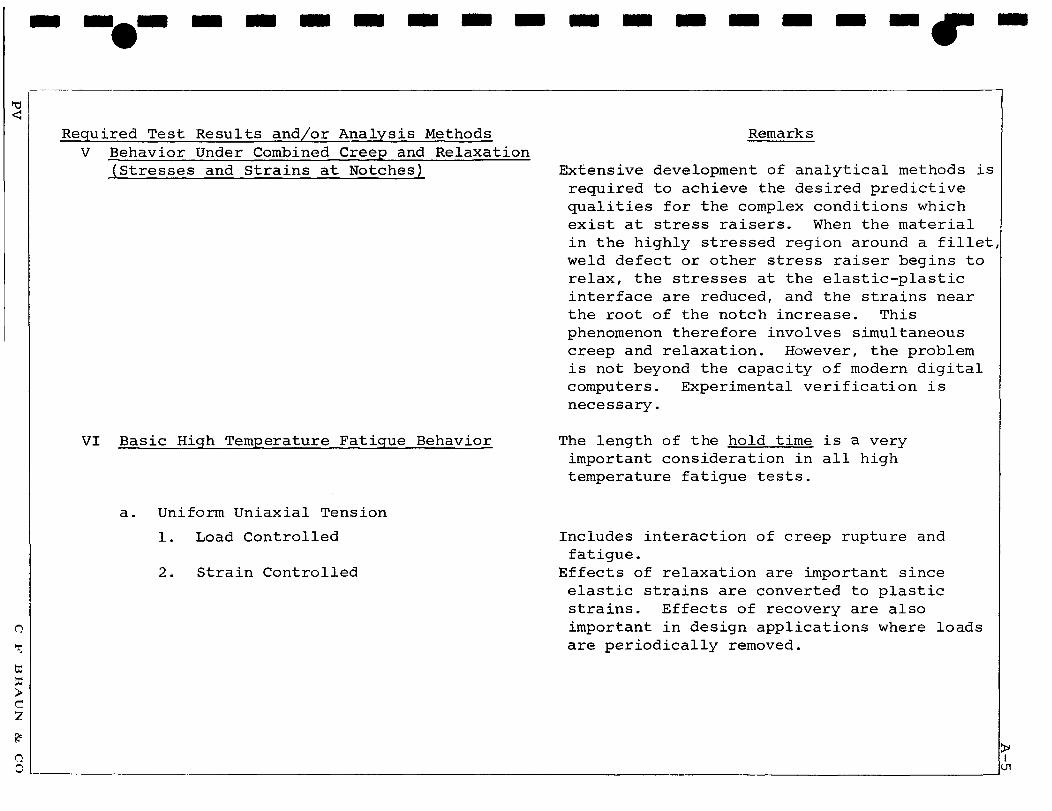
Required Test Results and/or Analysis Methods V Behavior Under Combined Creep and Relaxation
(Stresses and Strains at Notches)
VI Basic High Temperature Fatigue Behavior
a. Uniform Uniaxial Tension
1. Load Controlled
2. Strain Controlled
Remarks
Extensive development of analytical methods is required to achieve the desired predictive qualities for the complex conditions which exist at stress raisers. When the material in the highly stressed region around a fillet, weld defect or other stress raiser begins to relax, the stresses at the elastic-plastic interface are reduced, and the strains near the root of the notch increase. This phenomenon therefore involves simultaneous creep and relaxation. However, the problem is not beyond the capacity of modern digital computers. Experimental verification is necessary.
The length of the hold time is a very important consideration in all high temperature fatigue tests.
Includes interaction of creep rupture and fatigue.
Effects of relaxation are important since elastic strains are converted to plastic strains. Effects of recovery are also important in design applications where loads are periodically removed.

Required Test Results and/or Analysis Methods
b. Uniform Uniaxial Bending
1. Load Controlled
2. Strain Controlled
c. Uniform Biaxial Tension
1. Load Controlled
2. Strain Controlled
d. Notched
1. Load Controlled
2. Strain Controlled
e. Cumulative Fatigue
f. Cyclic Stress-Strain Properties
Remarks
Influenced by complex interaction effects of creep, relaxation and recovery. Extensive analysis methods development is required but is not beyond the capacity of modern digital computers. Once satisfactory constitutive relations are developed, stresses and strain can be calculated at notches subjected to cyclic loads in the creep range. Experimental verification is necessary.
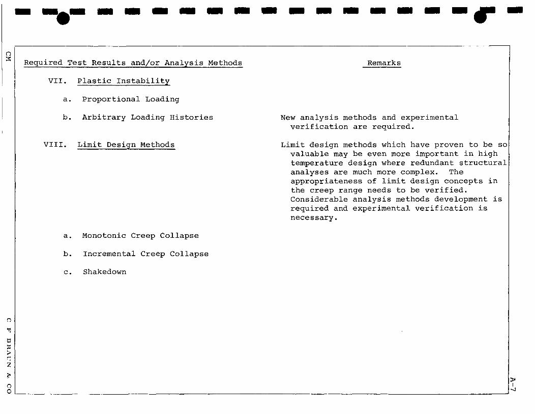
Required Test Results and/or Analysis Methods
VII. Plastic Instability
a. Proportional Loading
b. Arbitrary Loading Histories
VIII. Limit Design Methods
a. Monotonic Creep Collapse
b. Incremental Creep Collapse
c. Shakedown
Remarks
New analysis methods and experimental verification are required.
Limit design methods which have proven to be so valuable may be even more important in high temperature design where redundant structural analyses are much more complex. The appropriateness of limit design concepts in the creep range needs to be verified. Considerable analysis methods development is required and experimental verification is necessary.

![Aesthetics & Ergonomics Design Of Hyperbaric Oxygen ... & Ergonomics Design Of Hyperbaric Oxygen ... Pressure Vessel Design Manual –By Dennis R Moss. [4]. Pressure Vessel and piping](https://img.pdfslide.us/doc/110x75/5aa115077f8b9a89178ee71e/aesthetics-ergonomics-design-of-hyperbaric-oxygen-ergonomics-design-of-hyperbaric.jpg)


![PRESSURE VESSEL [Proses Pembuatan Pressure Vessel]](https://img.pdfslide.us/doc/110x75/546b26fab4af9fc2128b4e24/pressure-vessel-proses-pembuatan-pressure-vessel.jpg)
